WO2012133583A1 - Dispositif et procédé de séchage supercritique - Google Patents
Dispositif et procédé de séchage supercritique Download PDFInfo
- Publication number
- WO2012133583A1 WO2012133583A1 PCT/JP2012/058239 JP2012058239W WO2012133583A1 WO 2012133583 A1 WO2012133583 A1 WO 2012133583A1 JP 2012058239 W JP2012058239 W JP 2012058239W WO 2012133583 A1 WO2012133583 A1 WO 2012133583A1
- Authority
- WO
- WIPO (PCT)
- Prior art keywords
- drying
- liquid
- supercritical
- workpiece
- section
- Prior art date
- Legal status (The legal status is an assumption and is not a legal conclusion. Google has not performed a legal analysis and makes no representation as to the accuracy of the status listed.)
- Ceased
Links
Images








Classifications
-
- F—MECHANICAL ENGINEERING; LIGHTING; HEATING; WEAPONS; BLASTING
- F26—DRYING
- F26B—DRYING SOLID MATERIALS OR OBJECTS BY REMOVING LIQUID THEREFROM
- F26B1/00—Preliminary treatment of solid materials or objects to facilitate drying, e.g. mixing or backmixing the materials to be dried with predominantly dry solids
-
- H—ELECTRICITY
- H10—SEMICONDUCTOR DEVICES; ELECTRIC SOLID-STATE DEVICES NOT OTHERWISE PROVIDED FOR
- H10P—GENERIC PROCESSES OR APPARATUS FOR THE MANUFACTURE OR TREATMENT OF DEVICES COVERED BY CLASS H10
- H10P70/00—Cleaning of wafers, substrates or parts of devices
- H10P70/10—Cleaning before device manufacture, i.e. Begin-Of-Line process
- H10P70/15—Cleaning before device manufacture, i.e. Begin-Of-Line process by wet cleaning only
-
- H—ELECTRICITY
- H10—SEMICONDUCTOR DEVICES; ELECTRIC SOLID-STATE DEVICES NOT OTHERWISE PROVIDED FOR
- H10P—GENERIC PROCESSES OR APPARATUS FOR THE MANUFACTURE OR TREATMENT OF DEVICES COVERED BY CLASS H10
- H10P70/00—Cleaning of wafers, substrates or parts of devices
- H10P70/20—Cleaning during device manufacture
-
- H—ELECTRICITY
- H10—SEMICONDUCTOR DEVICES; ELECTRIC SOLID-STATE DEVICES NOT OTHERWISE PROVIDED FOR
- H10P—GENERIC PROCESSES OR APPARATUS FOR THE MANUFACTURE OR TREATMENT OF DEVICES COVERED BY CLASS H10
- H10P72/00—Handling or holding of wafers, substrates or devices during manufacture or treatment thereof
- H10P72/04—Apparatus for manufacture or treatment
- H10P72/0402—Apparatus for fluid treatment
- H10P72/0406—Apparatus for fluid treatment for cleaning followed by drying, rinsing, stripping, blasting or the like
-
- H—ELECTRICITY
- H10—SEMICONDUCTOR DEVICES; ELECTRIC SOLID-STATE DEVICES NOT OTHERWISE PROVIDED FOR
- H10P—GENERIC PROCESSES OR APPARATUS FOR THE MANUFACTURE OR TREATMENT OF DEVICES COVERED BY CLASS H10
- H10P72/00—Handling or holding of wafers, substrates or devices during manufacture or treatment thereof
- H10P72/04—Apparatus for manufacture or treatment
- H10P72/0402—Apparatus for fluid treatment
- H10P72/0406—Apparatus for fluid treatment for cleaning followed by drying, rinsing, stripping, blasting or the like
- H10P72/0408—Apparatus for fluid treatment for cleaning followed by drying, rinsing, stripping, blasting or the like for drying
Definitions
- the present invention relates to a supercritical drying apparatus, and more particularly to a supercritical drying apparatus capable of reusing a drying prevention liquid used for supercritical drying.
- Supercritical drying is a technology that dries a workpiece without damage by replacing the liquid with a supercritical fluid with high diffusibility and solubility, and then returning it to below the critical point to vaporize the supercritical fluid.
- a technique according to Patent Document 1 can be cited.
- Patent Document 1 introduces a technique in which a substrate is immersed in a transport pallet in which a chemical solution is immersed to perform liquid replacement, and the entire transport pallet is transported to a supercritical drying apparatus.
- an anti-drying liquid is supplied to the wafer so that the wafer does not dry and pattern collapse occurs in the drying chamber.
- alcohol solvents such as IPA are widely used.
- VOC volatile organic compounds
- IPA volatile organic compounds
- an object of the present invention is to provide a technique capable of saving liquid by reusing a drying prevention liquid used in supercritical drying.
- a supercritical drying apparatus includes a rinsing unit that cleans a workpiece with a rinsing liquid as a pretreatment for supercritical drying, and supercritical drying with respect to the workpiece that has been cleaned with the rinsing liquid.
- a supercritical drying section that performs the above process, and a transport section that transports the workpiece between the rinse section and the supercritical drying section, and the supercritical drying section contains the same components as the rinse liquid.
- An anti-drying liquid supply unit for supplying the anti-drying liquid, and the anti-drying liquid recovered from the supercritical drying unit by collecting the anti-drying liquid supplied from the anti-drying liquid supply unit to the supercritical drying unit.
- an anti-drying liquid supply part for supplying the liquid to the rinsing part, wherein the anti-drying liquid recovered from the supercritical drying part is used as at least a part of the rinsing liquid.
- the anti-drying liquid used during supercritical drying can be reused as a rinsing liquid.
- the amount of new rinsing liquid to be used can be reduced, which is superior in cost and has little environmental pollution.
- a cleaning process prior to the drying process and the supercritical drying can be performed.
- the rinse section includes a primary rinse section for performing a primary rinse, and a secondary rinse for cleaning the workpiece washed by the primary rinse section before transporting the workpiece to the supercritical drying section.
- a rinsing part, and the anti-drying liquid recovered from the supercritical drying part may be used in the primary rinsing part.
- the amount of new rinsing used can be reduced, and by using only new rinsing in the secondary rinsing section, liquid replacement with the rinsing liquid can be performed more reliably by rinsing multiple times.
- the surface of the workpiece after the rinse cleaning can be made cleaner.
- the supercritical drying apparatus includes a rinse and a conveyance unit that cleans a workpiece with a rinse liquid as a pretreatment for supercritical drying, and conveys the workpiece, and the rinse liquid.
- a supercritical drying section that performs supercritical drying on the washed workpiece; a drying prevention liquid supply section that supplies a drying prevention liquid containing the same components as the rinse liquid to the supercritical drying section; and the drying An anti-drying liquid feeding part for collecting the anti-drying liquid supplied to the supercritical drying part from an anti-living liquid supply part, and sending the anti-drying liquid collected from the supercritical drying part to the rinsing part;
- the drying prevention liquid recovered from the supercritical drying section is used as at least a part of the rinsing liquid.
- the anti-drying liquid used during supercritical drying can be reused as a rinsing liquid.
- the amount of new rinsing liquid to be used can be reduced, which is superior in cost and has little environmental pollution.
- a cleaning process prior to the drying process and the supercritical drying can be performed.
- a pre-treatment for cleaning with the rinse liquid it further includes a water washing section that performs washing washing of the workpiece.
- a water washing section a washing surface of the workpiece is placed in a vertical state, and the rinsing and transporting section is the processing section.
- the workpiece may be taken out from the water washing section so that the cleaning surface is vertical or downward, and then the workpiece is deformed to change the cleaning surface of the workpiece to be horizontal or upward, and the workpiece may be conveyed.
- the supercritical drying unit includes a processing unit that performs supercritical drying of the workpiece therein, and a high-pressure fluid supply unit that supplies a high-pressure fluid to the processing unit, and the processing unit and the high-pressure drying unit
- the fluid supply unit is connected by a first pipe, the processing unit and the drying prevention liquid supply unit are connected by a second pipe, and the processing unit and the drying prevention liquid feeding unit are connected.
- the space may be connected by a third pipe, and the processing section, the first pipe, the second pipe, and the third pipe may each have an oxide film.
- a supercritical drying apparatus includes a supercritical drying unit that performs supercritical drying on a workpiece, and the supercritical drying unit includes a rinse liquid as a pretreatment for supercritical drying.
- the rinsing and drying treatment unit that performs supercritical drying by supplying the drying prevention liquid containing the same components as the rinsing liquid after washing the workpiece and discharging the rinsing liquid is the same as the rinsing liquid
- An anti-drying liquid supply unit that supplies an anti-drying liquid containing components to the rinsing and drying processing unit, and the anti-drying liquid supplied to the rinsing and drying processing unit from the anti-drying liquid supply unit is recovered, and the rinsing and A drying prevention liquid feeding section for feeding the drying prevention liquid collected from the drying processing section to the rinsing and drying processing section, and at least the drying prevention liquid collected from the rinsing and drying processing section Said It is characterized by using as part of the scan solution.
- the drying preventing liquid can be reused as the rinsing liquid, and it is not necessary to provide a space for performing the rinsing cleaning separately from the supercritical drying section, and the entire apparatus can be made small.
- the supercritical drying unit includes a high-pressure fluid supply unit that supplies a high-pressure fluid to the rinsing and drying processing unit, and a rinse liquid supply unit that supplies the rinsing liquid to the rinsing and drying processing unit.
- the rinsing / drying processing unit and the high-pressure fluid supply unit are connected by a first pipe, and the rinsing / drying processing unit and the anti-drying liquid supply unit are connected by a second pipe,
- the rinse and the drying treatment section and the drying prevention liquid feeding section are connected by a third pipe, and the rinse and the drying treatment section and the rinse liquid supply section are connected by a fourth pipe,
- the rinse and drying processing unit, the first pipe, the second pipe, the third pipe, and the fourth pipe may each have an oxide film.
- the supercritical drying method includes cleaning a workpiece with a rinse liquid, transporting the cleaned workpiece to a supercritical drying section, and supplying the rinse liquid to the supercritical drying section. And supplying the anti-drying liquid containing the same components as the above, exposing the workpiece to the anti-drying liquid, filling the supercritical drying section with a supercritical fluid, and filling the anti-drying liquid with a supercritical fluid. Subsequent to evaporating the fluid in a supercritical state and drying the workpiece, collecting the anti-drying liquid supplied to the supercritical drying section, and at least washing another workpiece It is used as a part.
- the anti-drying liquid used during supercritical drying can be reused as a rinsing liquid.
- the amount of new rinsing liquid to be used can be reduced, which is superior in cost and has little environmental pollution.
- a cleaning process prior to the drying process and the supercritical drying can be performed.
- the cleaning with the rinse liquid includes primary cleaning and secondary cleaning, and the drying prevention liquid may be used as a part of the rinse liquid at the time of the primary cleaning when cleaning another workpiece. Good.
- the amount of new rinsing used can be reduced, and by using only new rinsing in the secondary rinsing section, liquid replacement with the rinsing liquid can be performed more reliably by rinsing multiple times.
- the surface of the workpiece after the rinse cleaning can be made cleaner.
- the supercritical drying method transports a workpiece to a supercritical drying section while washing with a rinse liquid, and the supercritical drying section contains the same components as the rinse liquid.
- Supplying a prevention liquid exposing the workpiece to the anti-drying liquid, filling the supercritical drying part with a fluid in a supercritical state, replacing the anti-drying liquid with a fluid in a supercritical state, and then in a supercritical state
- the fluid is vaporized to dry the workpiece, the anti-drying liquid supplied to the supercritical drying section is recovered, and used as a part of the rinse liquid when cleaning at least another workpiece.
- the anti-drying liquid used during supercritical drying can be reused as a rinsing liquid.
- the amount of new rinsing liquid to be used can be reduced, which is superior in cost and has little environmental pollution.
- a cleaning process prior to the drying process and the supercritical drying can be performed.
- the workpiece is washed with water as a pretreatment for washing with the rinse liquid, and the washing surface of the workpiece is in a vertical state during the washing, and then the posture of the workpiece is changed to change the posture of the workpiece.
- the workpiece may be conveyed by converting the cleaning surface to horizontal or upward.
- a workpiece is washed with a rinse liquid in a supercritical drying section, the rinse liquid is discharged from the supercritical drying section, and the supercritical drying section is discharged. And supplying an anti-drying liquid containing the same components as the rinse liquid, exposing the workpiece to the anti-drying liquid, filling the supercritical drying section with a supercritical fluid, and supercritically filling the anti-drying liquid.
- the supercritical fluid is vaporized, the workpiece is dried, the drying prevention liquid supplied to the supercritical drying section is recovered, and at least another workpiece is washed. It is used as a part of the rinse liquid.
- the drying preventing liquid can be reused as the rinsing liquid, and it is not necessary to provide a space for performing the rinsing cleaning separately from the supercritical drying section, and the entire apparatus can be made small.
- VOCs used as anti-drying liquid after rinsing in supercritical drying and before supercritical drying are returned to the supercritical drying chamber and reused as anti-drying liquid for reuse as wafers cleaned by rinsing. It came to the knowledge that there exists a possibility that the particle contained in the drying prevention liquid may adhere. As a result of diligent study, the present inventor used the drying prevention liquid as a rinsing cleaning liquid in front of the supercritical drying chamber or as a rinsing cleaning liquid in the supercritical drying chamber, so that the wafer is kept clean and used through cleaning and drying. It was found that the amount of VOC produced can be reduced.
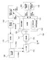
- FIG. 1 is a block diagram showing the overall configuration of a supercritical drying apparatus according to an embodiment of the present invention.
- a supercritical drying apparatus includes a rinsing unit 110, a supercritical drying unit 120, a transport unit 130, an anti-drying liquid supply unit 140, a high-pressure fluid supply unit 150, and a discharged liquid recovery.
- the workpiece 10 is an article that has undergone processes such as photolithography, etching, and ion implantation, and is an object to be cleaned and dried.
- the workpiece 10 is formed with, for example, an extremely finely patterned resist, a fine space manufactured by the MEMS technology, and the like.
- the workpiece 10 is subjected to various processes such as washing, conveyance, and drying as it is or in a state of being held by the workpiece holder.
- the workpiece 10 not only the workpiece 10 itself but also the workpiece 10 and a workpiece holder for holding the workpiece 10 may be included.
- the workpiece 10 is conveyed to the rinsing unit 110 after being washed with pure water or after being etched. Note that, in the drawings and the following description, an explanation will be given by taking an example of single-wafer processing of a workpiece, but a plurality of workpieces may be batch-processed collectively.
- the rinse part 110 is a part that rinses the workpiece 10 with the rinse liquid 20 as a pretreatment for supercritical drying.
- the rinse liquid 20 is supplied to the rinse section 110 from the rinse liquid supply section 180 and the liquid feeding section 170.
- the rinsing liquid 20 is usually a liquid having a surface tension smaller than that of pure water, and an alcohol solvent is used.
- IPA isopropyl alcohol
- the rinsing liquid supply unit 180 is usually connected to a tank containing alcohol, and supplies the alcohol in the tank to the rinsing unit 110.
- the liquid feeding unit 170 supplies the drying preventing liquid used for the supercritical drying to the rinsing unit 110. This mechanism will be described in detail later.
- the workpiece 10 is washed with the rinsing liquid 20 and liquid replacement with the rinsing liquid 20 is performed.
- the workpiece 10 cleaned in the rinse unit 110 is transported to the supercritical drying unit 120 by the transport unit 130.
- the transfer unit 130 is a general transfer robot arm, and may be any mechanism that can stably hold and transfer the workpiece 10. The mechanism is not particularly limited.
- the supercritical drying unit 120 is a part that performs supercritical drying on the workpiece 10.
- the supercritical drying unit 120 includes at least a processing unit 121, a gas-liquid separation unit 122, and a workpiece collection unit 123.
- the processing unit 121 is connected to the anti-drying liquid supply unit 140, the high-pressure fluid supply unit 150, and the gas-liquid separation unit 122, and the processing unit 121 and the gas-liquid separation unit 122 are connected to the discharged liquid recovery unit 160.
- FIG. 2 is a diagram for explaining the configuration of the supercritical drying section of the supercritical drying apparatus according to an embodiment of the present invention. Details of the configuration of the supercritical drying unit 120, the anti-drying liquid supply unit 140, the high-pressure fluid supply unit 150, and the discharged liquid recovery unit 160 will be described with reference to FIG. 2 together with FIG.
- the processing unit 121 is a pressure vessel (chamber) that performs supercritical drying on the workpiece 10 therein.
- the processing unit 121 when the workpiece 10 is installed in the processing unit 121 by the transport unit 130, the processing unit 121 is in an open state. When supercritical drying is performed on the workpiece 10 conveyed into the processing unit 121, the processing unit 121 is closed. Although illustration is omitted, after drying is completed, the processing unit 121 is opened again, and the workpiece 10 is carried out of the processing unit 121 by the transport unit 130 and stored in the workpiece collecting unit 123.
- the conveyance work of the workpiece 10 may be performed by the conveyance part 130, and the workpiece 10 may be conveyed by an individual conveyance means. As shown in FIG.
- the workpiece 10 is conveyed to the processing unit 121 in a state where the cleaning surface of the workpiece is in a horizontal state, and may be placed horizontally, or as shown in FIG. 3,
- the cleaning surface may be conveyed to the processing unit 121 in a vertical state and placed vertically.
- the rinse unit 110 can process a plurality of workpieces 10
- the processing unit 121 can process a plurality of workpieces 10, and supercritical drying can be performed on the plurality of workpieces 10 at once by batch processing. Good.
- the drying prevention liquid 30 is supplied to the processing unit 121 from the drying prevention liquid supply unit 140 through a pipe.
- the anti-drying liquid 30 a chemical liquid having a surface tension smaller than that of pure water and having an affinity for a supercritical fluid is usually used.
- alcohol it is desirable to use alcohol as the drying preventing liquid 30 and the rinsing liquid 20, and for example, IPA may be used.
- the processing unit 121 is supplied with a clean anti-drying liquid 30 from the anti-drying liquid supply unit 140 for each workpiece to be supercritically dried.
- the anti-drying liquid 30 is supplied to the processing unit 121 so that the solvent interface of the anti-drying liquid 30 comes to a position higher than the upper surface position of the workpiece 10 conveyed by the conveying unit 130. This prevents the workpiece 10 from drying before supplying the high-pressure fluid to cause pattern collapse or sticking, and replaces pure water remaining on the surface of the workpiece 10 to thereby prevent the interface between the gas phase and the liquid phase. It is also possible to prevent pattern collapse due to the interfacial tension of pure water.
- the fluid 40 that has been liquefied at a high pressure is supplied from the high-pressure fluid supply unit 150 to the processing unit 121 through a pipe.
- the fluid 40 may be any fluid that can be brought into a supercritical state by adjusting temperature and pressure.
- carbon dioxide has a low critical point (7.38 MPa, 31.1 ° C.) and is chemically stable, and therefore can be suitably used as a supercritical fluid.
- the fluid 40 may be supplied to the processing unit 121 in a supercritical state, or may be set to a supercritical state in the processing unit 121 after being supplied to the processing unit 121 in a liquefied state.
- the anti-drying liquid may flow and damage a part of the workpiece 10, so it is desirable to introduce the supercritical carbon dioxide into the processing unit 121.
- the fluid 40 in the supercritical state is dissolved from the vicinity of the interface of the drying preventing liquid 30. While further supplying the fluid 40, the drying preventing liquid 30 (including the supercritical fluid 40) is recovered by the discharge liquid recovery unit 160 and discharged out of the processing unit 120. In this way, the supercritical carbon dioxide is supplied, and the atmosphere around the workpiece 10 is replaced with the supercritical carbon dioxide from the anti-drying liquid 30.
- the processing unit 121 When the atmosphere around the workpiece 10 is replaced with carbon dioxide in a supercritical state, the processing unit 121 is decompressed. Due to the pressure change, carbon dioxide is in a gaseous state, and drying of the workpiece 10 is completed. After the carbon dioxide is collected from the processing unit 121, the workpiece 10 is carried out of the processing unit 121 by the workpiece collecting unit 123 and collected.
- the processing unit 121 After the supercritical drying, there may be a case where a liquid and a gas in which a part of the drying preventing liquid 30 and the high-pressure fluid 40 are mixed are prevalent in the processing unit 121.
- This mixture is recovered from the processing unit 121 through the gas-liquid separation unit 122.
- the gas-liquid separation unit 122 collects the mixture in the processing unit 121 through the exhaust liquid and exhaust pipes and valves of the processing unit 121.
- the gas-liquid separator 122 In the gas-liquid separator 122, the collected mixture is separated into gas and liquid.
- the gas-liquid separation unit 122 is, for example, two sets of pipes and valves provided in the processing unit 121. One is a gas discharge pipe and valve, and after supercritical drying, the valve is opened to discharge exhaust gas, that is, the high-pressure fluid 40 used for supercritical drying and the dry drying liquid 30 in the gaseous state from the processing unit 121. Is done. Exhaust gas is discarded after being removed so as not to affect the atmosphere.
- the other is a pipe and a valve for discharging liquid, and after supercritical drying, the discharged liquid 50 is discharged from the processing unit 121 by opening the valve.
- the content of the discharged liquid 50 is mainly the anti-drying liquid 30 used for supercritical drying, and the anti-drying liquid 30 is mixed with the high-pressure fluid 40 and particles or the like adhering to a minute amount on the workpiece.
- the discharged liquid is sent to the discharged liquid collection unit 160.
- the exhaust liquid recovery unit 160 recovers the exhaust liquid sent from the gas-liquid separation unit 122.
- the discharged liquid recovery unit 160 may be a tank, and may store the recovered discharged liquid 50.
- the effluent 50 is recovered from the gas-liquid separation unit 122 to the effluent recovery unit 160 through a pipe.
- a filter may be provided to remove impurities from the drainage liquid 50.
- the liquid feeding unit 170 has a pipe that connects the discharged liquid collecting unit 160 and the rinsing unit 110 and a mechanism that sends the liquid collected by the discharged liquid collecting unit 160 to the rinsing unit 110, and the discharged liquid passes through the liquid feeding unit 170.
- the discharged liquid recovery unit 160 sends the liquid to the rinse unit 110.
- the transport unit 130 transports the workpiece 10 placed in the rinse unit 110 to the processing unit 121 of the supercritical drying unit 120 and is placed on the processing unit 121.
- the conveyance unit 130 quickly conveys the workpiece 10 to the processing unit 121 so that the workpiece 10 is transferred to the processing unit 121 until the surface of the workpiece 10 washed with the rinse liquid is dried.
- the conveyance unit 130 may convey the workpiece 10 from the apparatus in the previous process to the rinse unit 110.
- FIG. 4 is a block diagram showing an outline of an apparatus when water washing is performed as a pre-rinse washing process in the supercritical drying apparatus according to the embodiment of the present invention.
- a rinsing unit 220 that performs a pre-process of the rinsing unit 110 and a workpiece 190 that transports the workpiece from the rinsing unit 220 to the rinsing unit 110 are provided.
- the workpiece 10 is washed with pure water.
- the workpiece 10 is washed with pure water to remove particles and the like. Moreover, drying of the workpiece 10 is also prevented by pure water cleaning.
- the water washing unit 220 may batch-process a plurality of workpieces 10 at once.
- the workpiece 10 washed in the water washing unit 220 is conveyed to the rinse unit 110 by the conveyance unit 190.
- the transport unit 190 it is desirable to use the transport unit 130 described above. This is because the entire apparatus can be miniaturized by using a common transport unit.
- the supercritical drying apparatus may be systemized including the water washing unit 220.
- the drying preventing liquid 30 used in the processing unit 121 can be reused in the rinsing unit 110, and the amount of new rinsing liquid used can be reduced, resulting in excellent cost.
- a supercritical drying apparatus with less environmental pollution is provided.
- the supercritical fluid has an advantage of low viscosity and does not damage the pattern, but has a weak ability to remove particles.
- the processing unit 121 is supplied with the clean anti-drying liquid 30 from the anti-drying liquid supply unit 140 for each workpiece to be dried. Therefore, the processing unit 121 is excellent in cost and cleanability as described above. It becomes.
- a plurality of rinse sections 110 may be provided, and the workpiece 10 may be rinsed multiple times.
- the anti-drying solution may be reused only for rinsing in one of the rinsing sections.
- the rinse section 110 performs rinse cleaning a plurality of times will be described.
- FIG. 5 is a block diagram showing an example in which a plurality of rinse sections are provided in the supercritical drying apparatus according to an embodiment of the present invention.
- the supercritical drying apparatus of FIG. 5 includes, as the rinsing unit 110, a first rinsing unit 111 that performs primary rinsing and a second rinsing unit 112 that performs secondary rinsing.
- the liquid feeding unit 170 is connected to the first rinse unit 111, but is not connected to the second rinse unit 112.
- the collected anti-drying liquid may be used in either the first rinse 111 or the second rinse part 112, but when the rinse cleaning is performed a plurality of times, the rinse liquid 20 used for the subsequent rinse cleaning is cleaner. Since it is desirable, the aspect utilized in the 1st rinse part 111 is desirable. With the configuration shown in FIG.
- the first rinsing unit 111 it is possible to reduce the amount of new rinsing liquid used by using the discharged liquid 50 fed from the liquid feeding unit 170 for rinsing.
- the second rinse part 112 by using only a new rinse liquid, the liquid replacement from the pure water to the rinse liquid 20 can be more reliably performed by multiple rinse cleaning, and the workpiece 10 after the rinse cleaning is performed. The surface of can be made into a clean state.
- the workpiece 10 When the workpiece 10 is transported between the first rinsing unit 111 and the second rinsing unit 112, it may be performed by the transport unit 130 described above, and another transport unit may be provided. It is desirable to use a common transport unit because the entire apparatus can be downsized.
- primary rinse and secondary rinse are called according to the cleanliness level of a workpiece.
- the secondary rinsing refers to rinsing with the highest level of cleanliness performed immediately before being conveyed to the supercritical drying section 120, and the primary rinsing refers to the entire rinsing before the secondary rinsing. Therefore, the primary rinse part may further have a plurality of rinse parts.
- FIG. 6 is a block diagram showing an outline of a supercritical drying apparatus according to another embodiment of the present invention.
- a supercritical drying apparatus includes a rinsing / conveying unit 210, a supercritical drying unit 120, an anti-drying liquid supply unit 140, a high-pressure fluid supply unit 150, and a discharged liquid recovery unit. 160, a liquid feeding unit 170, a rinsing liquid supply unit 180, and a water washing unit 220.
- the rinse section 110 and the transport section 130 in the above-described embodiment are integrated to constitute the rinse and transport section 210.
- the liquid feeding unit 170 and the rinse liquid supply unit 180 feed the rinse liquid to the rinse and transport unit 210.
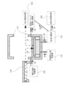
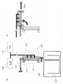
- FIG. 7 is a schematic diagram for explaining the configuration of the rinsing and conveying unit 210 in the supercritical drying apparatus according to another embodiment of the present invention, and FIG. 7 (A) pulls up the workpiece 10 from the water washing unit 220.
- FIG. 7B is a schematic diagram for explaining the operation of conveying the workpiece 10 while rinsing the workpiece 10.
- the rinsing and conveying unit 210 includes a workpiece gripping unit 211, a rotation mechanism 212, and a pipe 213.
- the workpiece 10 is mechanically held by the workpiece holding portion 211.
- the posture of the workpiece 10 held by the workpiece holding unit 211 is changed by the rotation mechanism 212.
- the rinse liquid supplied from the rinse liquid supply unit 180 and the liquid feeding unit 170 is guided to the workpiece 10 through the pipe 213.
- the workpiece 10 is allowed to stand in a vertical state (a state in which the cleaning surface is perpendicular to the horizontal plane) in the water washing section 220, and is pulled upward in that state.
- a vertical state a state in which the cleaning surface is perpendicular to the horizontal plane
- the workpiece 10 may be placed in a wafer carrier within the washing unit 220. While the workpiece 10 is pulled up, a rinsing liquid is supplied from the pipe 213 to the workpiece 10, and liquid replacement from pure water to alcohol is performed.
- pure water can easily flow downward due to gravity, and liquid replacement can be performed efficiently.
- the cleaning surface can be pulled up so that pure water flows downward.
- the cleaning surface may be tilted within a range of ⁇ 30 ° from the vertical state, and the cleaning surface of the workpiece 10 may be pulled upward with the cleaning surface facing downward.
- the workpiece gripping unit 211 is rotated by the rotation mechanism 212, and the workpiece is moved from the vertical state to the horizontal state (the cleaning surface is changed).
- the processing unit 121 of the supercritical drying unit 120 since the workpiece 10 is usually installed in a horizontal state, the posture can be smoothly transferred to the supercritical drying unit 120 by changing the posture to the horizontal state in the rinsing process. It becomes possible. Therefore, by performing cleaning while transporting to the supercritical drying unit 120 in a horizontal state, the processing time required for cleaning and transporting the workpiece 10 can be shortened.
- the cleaning surface can be conveyed upward so that the rinsing liquid is less likely to flow downward.
- the cleaning surface of the workpiece 10 may be transported with the cleaning surface inclined upward within a range of ⁇ 30 ° from the upward horizontal state.
- the rinse and the conveyance part 210 are provided with the mechanism which can be expanded-contracted in the horizontal direction, and the workpiece 10 can be moved.
- the whole apparatus can be made small by comprising integrally as the rinse and the conveyance part 210 rather than providing a rinse part and a conveyance part separately.
- one of the first rinse unit 111 and the second rinse unit 112 described in the first embodiment is used as the rinse and transport unit 210, and liquid is fed to both or either of them. It is good also as a structure which connects the part 170 and reuses the drying prevention liquid 30.
- FIG. 1 is a structure which connects the part 170 and reuses the drying prevention liquid 30.
- the rinsing and conveying unit 210 does not need to include the rotation mechanism 212 and the posture of the workpiece 10 is changed as shown in FIG.
- the processed material 10 may be transported from the water washing section 220 to the supercritical drying section 120 without causing it to occur.
- the workpiece 10 is a wafer
- one or more wafers may be transferred from the water washing unit 220 to the supercritical drying unit 120 together with the wafer carrier storing one or more wafers.
- Embodiment 3 With reference to FIG. 9, the supercritical drying apparatus which concerns on Embodiment 3 of this invention is demonstrated.
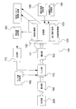
- FIG. 9 is a block diagram showing an outline of a supercritical drying apparatus according to Embodiment 3 of the present invention.
- FIG. 9 The basic configuration of FIG. 9 and the details of each configuration are the same as those of the first and second embodiments, but the processing unit 121 of the first and second embodiments can also perform a rinse cleaning process.
- a rinsing and drying processing unit 124 is different in that the rinsing liquid 20 is supplied from the rinsing liquid supply unit 180 and the liquid feeding unit 170 to the rinsing and drying processing unit 124. Since the processing unit 121 performs the rinse cleaning process and the supercritical drying process, it is expected that the apparatus is miniaturized and the transport operation is simplified.
- the rinsing and drying processing unit 124 has a function of performing rinsing cleaning inside the processing unit 121 in addition to the function of the processing unit 121.
- the rinsing liquid 20 is supplied from the rinsing liquid supply unit 180 and the liquid feeding unit 170 to the rinsing and drying processing unit 124.
- the drying prevention liquid 30 is supplied from the drying prevention liquid supply unit 140, but the rinse liquid 20 and the drying prevention liquid 30 may be liquids containing the same components.
- rinsing cleaning is performed using the supplied rinsing liquid 20, and liquid replacement is performed on the workpiece 10 conveyed to the rinsing and drying processing unit 124.
- the rinsing liquid 20 is discharged from the rinsing and drying processing section 124 through the gas-liquid separation section 122 and is collected by the discharged liquid collection section 160.
- the anti-drying liquid 30 is supplied from the anti-drying liquid supply section 140 to the rinsing and drying processing section 124. Subsequent processing is as described in the first and second embodiments.
- the rinse and transport unit 210 in FIG. 9 may be the rinse unit 110 and the transport unit 130, and does not have any configuration, and is directly processed into the rinse and dry processing unit 124 from the water washing unit 220.
- the object 10 may be conveyed.
- the collected discharged liquid 50 is reused as the anti-drying liquid 30 in the rinsing and drying processing unit 124.
- the discharged liquid 50 once used in the rinse cleaning or the drying process is used as the anti-drying liquid 30, there is a risk that the processed product 10 after the drying process may be in a clean state.
- the effluent 50 is not used as the drying preventing liquid 30.
- the drying preventing liquid 30 can be reused as the rinsing liquid 20 in the rinsing and drying processing unit 124, and it is not necessary to provide a space for performing the rinsing cleaning separately from the supercritical drying unit. Can be small.
- the rinsing liquid 20 is supplied to the rinsing and drying processing unit 124 in which the workpiece 10 is installed to the workpiece 10. Perform liquid replacement. Thereafter, all of the rinsing liquid 20 may be discharged from the rinsing and drying processing section 124, and then the anti-drying liquid 30 may be supplied to fill the rinsing and drying processing section with the anti-drying liquid 30. Further, as shown in FIG. 15 (b), the rinsing liquid 20 is first supplied to the rinsing and drying processing unit 124 in which the workpiece 10 is installed to perform liquid replacement on the workpiece 10.
- a part of the rinsing liquid 20 is discharged from the rinsing and drying processing unit 124, for example, half removed, and then the drying preventing liquid 30 is supplied, and the rinsing and drying processing unit 124 is filled with the rinsing liquid 20 and the drying preventing liquid 30. Also good.
- the method of supplying the rinsing liquid 20 and the drying prevention liquid 30 to the rinsing and drying processing unit 124 may vary depending on the cleanliness required for the workpiece 10.
- the supercritical drying apparatus according to FIG. 16 will be described.
- liquid replacement is performed in the supercritical drying unit with respect to the supercritical drying unit 120 that performs supercritical drying and its pretreatment, and the workpiece 10 conveyed in the supercritical drying unit.
- the supercritical drying part from the drainage liquid recovery part 160 to the drainage liquid recovery part 160 stored as a part of the liquid 20 and the recovered anti-drying liquid 30 as at least part of the replacement liquid 20 during the liquid replacement process.
- a transport unit 215 is provided.
- the configuration of the transport unit 215 is the same as that of the transport unit 130 and the transport unit 190.
- pure water and / or the rinsing liquid 20 may be supplied.
- the collected discharged liquid 50 is fed from the liquid feeding unit 170 to the rinsing and drying processing unit 124 as the rinse liquid 20.
- a filter such as an adsorbent may be provided to remove impurities from the discharged liquid 50.
- a pipe for directly feeding the rinsing liquid 20 to the rinsing and drying processing section 124 is provided.
- a pipe for connecting the rinsing liquid 20 to the rinsing and drying processing section 124 from the rinsing liquid supply section 180 may be provided, or a pipe for supplying the rinsing liquid supply section 180 may be provided. May be.
- the rinsing and drying processing unit 124 first, liquid replacement with the rinsing liquid 20 is performed. Next, the rinsing liquid 20 used for the liquid replacement is discharged from the rinsing and drying processing unit 124 and discarded. Then, after supplying the drying prevention liquid 30 to the rinsing and drying processing unit 124, the fluid 40 is supplied to the rinsing and drying processing unit 124 to perform supercritical drying. After drying, the anti-drying liquid 30 is discharged from the rinsing and drying processing unit 124, and the fluid 40 is discharged.
- the rinse and drying processing unit 124 and the piping connecting the rinsing and drying processing unit 124 and each component may be subjected to a passivation process described later.
- the rinsing liquid 20 and the drying preventing liquid 30 can be reused as the rinsing liquid 20, and it is not necessary to provide a space for performing the rinsing cleaning separately from the supercritical drying section, and the entire apparatus can be made small. Can do.
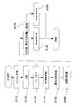
- FIG. 10 is a flowchart showing an example of a supercritical drying method according to another embodiment of the present invention.
- pre-processes such as photolithography, etching, and ion implantation are performed on the workpiece 10 (S110).
- the workpiece 10 subjected to the pre-process is conveyed to the water washing section 220 by the carrier 230 or the like, and is immersed in pure water and washed (S120).
- the carrier 230 is immersed in the water washing section 220, damage to the fine pattern can be suppressed by making the cleaning surface of the workpiece 10 vertical.
- the workpiece 10 washed with pure water is washed with the rinsing liquid 20 in the rinsing section 110 and the rinsing and conveying section 210, and liquid replacement from pure water to rinsing liquid is performed (S130).
- the liquid replacement may be performed a plurality of times. It is desirable that the workpiece 10 is pulled up from the water washing section 220 in a vertical state, and the posture is changed to a horizontal state while supplying a rinsing liquid.
- the rinse-cleaned workpiece 10 is transported to the supercritical drying unit 120 by the transport unit 130 and the rinse and transport unit 210 and stored in the processing unit 121 in the open state.
- the drying prevention liquid 30 is supplied from the drying liquid supply unit 140 to prevent the workpiece 10 from drying before the supercritical drying process (S140). .
- liquid replacement with the rinsing liquid may be performed after the conveyance by the conveyance unit 215 or the rinsing and conveyance unit 210.
- the fluid 40 is supplied from the high-pressure fluid supply unit 150 to the processing unit 121 (S150).
- the fluid 40 may be changed from a liquid state to a supercritical state after being supplied in advance.
- the anti-drying fluid may flow and damage a part of the workpiece 10, so it is desirable to introduce the high-pressure fluid 40 that has become a supercritical state into the processing unit 121 in advance.
- the pressure is increased and the temperature is increased until the supercritical state is reached in the processing unit 121.
- the fluid 40 in a supercritical state is dissolved from the interface of the drying preventing liquid 30.
- the fluid 40 is supplied and the anti-drying liquid 30 is discharged. Thereafter, the inside of the processing unit 121 is depressurized to an atmospheric pressure state, the fluid is vaporized, and a drying process is performed (S160).
- the gas-liquid separator 122 separates the effluent 50 and the exhaust gas, and the effluent 50 is collected by the effluent collector 160 (S170).
- the separated exhaust gas is detoxified.
- the collected discharged liquid 50 is fed to the rinsing unit 110 or the rinsing and conveying unit 210 through the liquid feeding unit 170 (S180).
- the discharged liquid 50 thus fed is used as a part of the rinse liquid 20 when the next workpiece 10 is washed.
- the workpiece 10 that has been subjected to the drying process is collected (S190).
- the collected discharged liquid 50 is sent to the rinsing and drying processing section 124 through the liquid feeding section 170 and used as a part of the rinsing liquid 20 for cleaning the next workpiece 10. May be.
- the drying preventing liquid 30 used in the processing unit 121 can be reused in the rinsing unit 110 and the rinsing and transporting unit 210, and the amount of new rinsing liquid used can be reduced, resulting in cost reduction. Excellent supercritical drying process with less environmental pollution.
- Embodiment 5 Next, with reference to FIG.11 and FIG.12, the supercritical drying apparatus which concerns on Embodiment 5 of this invention is demonstrated. Before that, in order to facilitate understanding of the supercritical apparatus according to Embodiment 5, the background to the invention will be briefly described.
- the present embodiment is characterized in that a passivation process is performed on the rinsing section and the drying processing section of the supercritical drying apparatus and the pipes connecting the components.
- the passivation process is preferably performed on the supercritical drying apparatus according to each of the above-described embodiments (Embodiments 1 to 4).
- or rinse part in the supercritical apparatus which concerns on each embodiment, the drying process part, and the passivation process of piping which connects each structure are demonstrated.
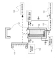
- FIG. 11 is a schematic diagram including piping for explaining the configuration of the supercritical drying apparatus according to Embodiments 1 and 2 of the present invention.
- FIG. 12 is a schematic diagram including piping for explaining the configuration of the supercritical drying apparatus according to the third embodiment of the present invention. The details of each configuration excluding the pipes in Embodiments 1 to 3 described above will not be described below.
- the high-pressure fluid supply unit 150 and the processing unit 121 are connected by a first pipe 310.
- the high pressure fluid 40 is supplied from the high pressure fluid supply unit 150 to the processing unit 121 through the first pipe 310.
- the drying prevention liquid supply unit 140 and the processing unit 121 are connected by a second pipe 320.
- the anti-drying liquid 30 is supplied from the anti-drying liquid supply unit 140 to the processing unit 121 through the second pipe 320.
- the gas-liquid separation unit 122 and the processing unit 121 are connected by a third pipe 330.
- An exhaust liquid 50 containing fluid or gas discharged after supercritical drying is sent from the processing unit 121 to the gas-liquid separation unit through the third pipe 330.
- the block 190 that removes and discards the gas and the processing unit 121 are connected by another pipe 335.
- the gas 40 is sent through the other pipe 335 from the processing unit 121 to the block 190 where the gas is detoxified and discarded.
- the supercritical drying apparatus of FIG. 12 has a rinsing and drying processing unit 124 instead of the processing unit 121 of FIG. Then, between the rinsing and drying processing unit 124, the high-pressure fluid supply unit 150, the anti-drying liquid supply unit 140, the gas-liquid separation unit 122, and the block 190 that removes and discards the gas, the pipes 310, 320, It is the same as that of the supercritical drying apparatus of FIG.
- the rinsing liquid supply unit 180 and the processing unit 121 are connected by a fourth pipe 340.
- the rinsing liquid 20 is supplied from the rinsing liquid supply unit 180 to the rinsing and drying processing unit 124 through the fourth pipe 340.
- the interior of the processing unit 121 and the chambers of the rinsing and drying processing unit 124 are usually made of stainless steel.
- stainless steel is usually used as a material for each of the pipes 310 to 340.
- a pressure of about 12 MPa is applied to the processing unit 121, the rinsing and drying processing unit 124, and each of the pipes 310 to 340, and this high pressure causes Fe, Cr, Ni, and the like. It is discharged from the processing unit 121 made of stainless steel, the rinsing and drying processing unit 124, and the pipes 310 to 340, and is discharged from the processing unit 121, the rinsing and drying processing unit 124, the pipings 310 to 340, and the substrate surface. May be contaminated with metal. If the inside of the processing unit 121 is contaminated with metal, the recovered effluent 50 is also contaminated with metal as a result after the supercritical drying process. Even when the effluent 50 is reused as the rinsing liquid 20, the rinsing is performed. The liquid 20 will be in the state contaminated with the metal.
- the processing unit 121, the rinsing and drying processing unit 124 are preferable.
- the surface treatment of each of the pipes 310 to 340 may be performed, and a coating may be applied to the internal surface of each component to prevent metal discharge.
- a passivation treatment is preferable.
- ozone is supplied to the inside of each component of the processing unit 121, the rinsing and drying processing unit 124, and each of the pipes 310 to 340 to oxidize Cr on the internal surface of each component to form an oxide film. This is done by forming.
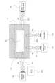
- FIG. 13 is a schematic diagram for explaining an example of a passivation processing method in the supercritical drying apparatus according to Embodiments 1 and 2 of the present invention.
- FIG. 14 is a schematic diagram for explaining an example of a passivation treatment method in the supercritical drying apparatus according to Embodiment 3 of the present invention.
- the ozone supply unit 400 is connected to the processing unit 121 or the rinsing and drying processing unit 124 through the first pipe 310.
- an oxide film is formed on the surface of the stainless steel.
- the ozone gas 60 compressed at a high concentration is supplied from the ozone supply unit 400.
- the ozone gas 60 is supplied to the processing unit 121 or the rinsing and drying processing unit 124 through the first pipe 310, and is supplied to the pipes 320 to 340 from the processing unit 121 or the rinsing and drying processing unit 124.
- the ends of the pipes 320 to 340 are sealed, and each component in the region P surrounded by the double chain line is exposed to the ozone gas 60.
- the valves of the pipes 320 to 340 may be exposed to the ozone gas 60 by closing the valves of the pipes 320 to 340.
- the ozone gas 60 exposes the processing unit 121, the rinsing and drying processing unit 124, and the pipes 310 to 340 formed of stainless steel, and as a result, an oxide film is formed on the internal surface of the stainless steel of each configuration, and the passivation is performed. Is complete. The thickness of the oxide film is several nm.
- the ozone 60 is exhausted to the block 190 for detoxifying and discarding the gas through another pipe 335, and discarded after the detoxification. Thereafter, the ozone supply unit 400 is replaced with the high-pressure fluid supply unit 150, and a supercritical drying process is performed.
- the above passivating treatment reduces metal discharge from the rinsing and drying processing section and each pipe, thereby maintaining good cleanliness of the supercritical drying section, and in the rinsing and drying processing section, used anti-drying liquid. And metal contamination of the workpiece can be prevented.
- a cleaner rinsing liquid can be used when the anti-drying liquid is reused as a rinsing liquid.
Landscapes
- Engineering & Computer Science (AREA)
- Mechanical Engineering (AREA)
- General Engineering & Computer Science (AREA)
- Cleaning Or Drying Semiconductors (AREA)
- Cleaning In General (AREA)
- Cleaning By Liquid Or Steam (AREA)
Abstract
L'objet de la présente invention consiste à permettre la réutilisation d'une solution antisiccative qui a été utilisée pour un séchage supercritique.
Un dispositif de séchage supercritique est doté d'une unité de rinçage (110) pour le nettoyage d'une pièce avec une solution de rinçage (20) en tant que procédé préalable au séchage supercritique, d'une unité de séchage supercritique (120) pour la réalisation du séchage supercritique de la pièce nettoyée avec ladite solution de rinçage (20), et d'une unité de transport (130) pour le transport de la pièce entre ladite unité de rinçage (110) et ladite unité de séchage supercritique (120). Ladite unité de séchage supercritique (120) comporte une unité d'alimentation en solution antisiccative (140) permettant d'introduire une solution antisiccative (30) comprenant le même composant que ladite solution de rinçage (20) et une unité de transport de solution antisiccative (170) permettant de recueillir la solution antisiccative (30) introduite par ladite unité d'alimentation en solution antisiccative (140) dans ladite unité de séchage supercritique (120) et de transporter la solution antisiccative (30) recueillie depuis ladite unité de séchage supercritique (120) jusqu'à ladite unité de rinçage (110), la solution antisiccative (30) recueillie depuis ladite unité de séchage supercritique (120) étant réutilisée au moins partiellement dans ladite solution de rinçage (20).
Priority Applications (2)
| Application Number | Priority Date | Filing Date | Title |
|---|---|---|---|
| JP2013507694A JP6048400B2 (ja) | 2011-03-30 | 2012-03-28 | 超臨界乾燥装置及び超臨界乾燥方法 |
| US14/040,864 US20140130367A1 (en) | 2011-03-30 | 2013-09-30 | Supercritical drying device and supercritical drying method |
Applications Claiming Priority (4)
| Application Number | Priority Date | Filing Date | Title |
|---|---|---|---|
| JP2011-076162 | 2011-03-30 | ||
| JP2011076162 | 2011-03-30 | ||
| JP2011146509 | 2011-06-30 | ||
| JP2011-146509 | 2011-06-30 |
Related Child Applications (1)
| Application Number | Title | Priority Date | Filing Date |
|---|---|---|---|
| US14/040,864 Continuation US20140130367A1 (en) | 2011-03-30 | 2013-09-30 | Supercritical drying device and supercritical drying method |
Publications (1)
| Publication Number | Publication Date |
|---|---|
| WO2012133583A1 true WO2012133583A1 (fr) | 2012-10-04 |
Family
ID=46931290
Family Applications (1)
| Application Number | Title | Priority Date | Filing Date |
|---|---|---|---|
| PCT/JP2012/058239 Ceased WO2012133583A1 (fr) | 2011-03-30 | 2012-03-28 | Dispositif et procédé de séchage supercritique |
Country Status (3)
| Country | Link |
|---|---|
| US (1) | US20140130367A1 (fr) |
| JP (1) | JP6048400B2 (fr) |
| WO (1) | WO2012133583A1 (fr) |
Cited By (34)
| Publication number | Priority date | Publication date | Assignee | Title |
|---|---|---|---|---|
| EP2854163A1 (fr) * | 2013-09-30 | 2015-04-01 | Shibaura Mechatronics Corporation | Dispositif et procédé de traitement des substrats |
| KR20150088829A (ko) * | 2012-11-26 | 2015-08-03 | 어플라이드 머티어리얼스, 인코포레이티드 | 고 종횡비 반도체 디바이스 구조들에 대한 오염물 제거를 갖는 무-스틱션 건조 프로세스 |
| JP2017104908A (ja) * | 2015-12-11 | 2017-06-15 | ズース マイクロテック フォトニック システムズ インコーポレイテッド | レーザ加工後のデブリ除去システムのための犠牲層及び除去方法 |
| US10283344B2 (en) | 2014-07-11 | 2019-05-07 | Applied Materials, Inc. | Supercritical carbon dioxide process for low-k thin films |
| US10304703B2 (en) | 2015-10-04 | 2019-05-28 | Applied Materials, Inc. | Small thermal mass pressurized chamber |
| US10529585B2 (en) | 2017-06-02 | 2020-01-07 | Applied Materials, Inc. | Dry stripping of boron carbide hardmask |
| US10529603B2 (en) | 2017-03-10 | 2020-01-07 | Micromaterials, LLC | High pressure wafer processing systems and related methods |
| US10566188B2 (en) | 2018-05-17 | 2020-02-18 | Applied Materials, Inc. | Method to improve film stability |
| US10573510B2 (en) | 2015-10-04 | 2020-02-25 | Applied Materials, Inc. | Substrate support and baffle apparatus |
| US10622214B2 (en) | 2017-05-25 | 2020-04-14 | Applied Materials, Inc. | Tungsten defluorination by high pressure treatment |
| US10636669B2 (en) | 2018-01-24 | 2020-04-28 | Applied Materials, Inc. | Seam healing using high pressure anneal |
| US10636677B2 (en) | 2017-08-18 | 2020-04-28 | Applied Materials, Inc. | High pressure and high temperature anneal chamber |
| US10643867B2 (en) | 2017-11-03 | 2020-05-05 | Applied Materials, Inc. | Annealing system and method |
| US10675581B2 (en) | 2018-08-06 | 2020-06-09 | Applied Materials, Inc. | Gas abatement apparatus |
| US10685830B2 (en) | 2017-11-17 | 2020-06-16 | Applied Materials, Inc. | Condenser system for high pressure processing system |
| US10704141B2 (en) | 2018-06-01 | 2020-07-07 | Applied Materials, Inc. | In-situ CVD and ALD coating of chamber to control metal contamination |
| US10714331B2 (en) | 2018-04-04 | 2020-07-14 | Applied Materials, Inc. | Method to fabricate thermally stable low K-FinFET spacer |
| US10720341B2 (en) | 2017-11-11 | 2020-07-21 | Micromaterials, LLC | Gas delivery system for high pressure processing chamber |
| US10748783B2 (en) | 2018-07-25 | 2020-08-18 | Applied Materials, Inc. | Gas delivery module |
| US10777405B2 (en) | 2015-10-04 | 2020-09-15 | Applied Materials, Inc. | Drying process for high aspect ratio features |
| US10847360B2 (en) | 2017-05-25 | 2020-11-24 | Applied Materials, Inc. | High pressure treatment of silicon nitride film |
| US10854483B2 (en) | 2017-11-16 | 2020-12-01 | Applied Materials, Inc. | High pressure steam anneal processing apparatus |
| US10957533B2 (en) | 2018-10-30 | 2021-03-23 | Applied Materials, Inc. | Methods for etching a structure for semiconductor applications |
| US10998200B2 (en) | 2018-03-09 | 2021-05-04 | Applied Materials, Inc. | High pressure annealing process for metal containing materials |
| US11018032B2 (en) | 2017-08-18 | 2021-05-25 | Applied Materials, Inc. | High pressure and high temperature anneal chamber |
| US11133174B2 (en) | 2015-10-04 | 2021-09-28 | Applied Materials, Inc. | Reduced volume processing chamber |
| US11177128B2 (en) | 2017-09-12 | 2021-11-16 | Applied Materials, Inc. | Apparatus and methods for manufacturing semiconductor structures using protective barrier layer |
| US11227797B2 (en) | 2018-11-16 | 2022-01-18 | Applied Materials, Inc. | Film deposition using enhanced diffusion process |
| JP2022173634A (ja) * | 2021-05-10 | 2022-11-22 | 東京エレクトロン株式会社 | 基板処理装置および基板処理方法 |
| US11581183B2 (en) | 2018-05-08 | 2023-02-14 | Applied Materials, Inc. | Methods of forming amorphous carbon hard mask layers and hard mask layers formed therefrom |
| JP2023043987A (ja) * | 2021-09-17 | 2023-03-30 | キオクシア株式会社 | 基板処理装置及び基板処理方法 |
| US11749555B2 (en) | 2018-12-07 | 2023-09-05 | Applied Materials, Inc. | Semiconductor processing system |
| US11901222B2 (en) | 2020-02-17 | 2024-02-13 | Applied Materials, Inc. | Multi-step process for flowable gap-fill film |
| JP2024113080A (ja) * | 2019-10-10 | 2024-08-21 | 東京エレクトロン株式会社 | 基板処理システム |
Families Citing this family (5)
| Publication number | Priority date | Publication date | Assignee | Title |
|---|---|---|---|---|
| KR101874901B1 (ko) * | 2011-12-07 | 2018-07-06 | 삼성전자주식회사 | 기판 건조 장치 및 방법 |
| AU2015265420B2 (en) * | 2014-05-30 | 2020-02-27 | Pelican Biotech & Chemical Labs Pvt Ltd | Novel design of multiple microwave/radiofrequency (MW/RF) magnetrons heated single vessel/reactor/chamber and its various applications including a novel dehydration process employing solvent extraction and solvent recovery |
| KR102168153B1 (ko) * | 2018-10-10 | 2020-10-22 | (주)유진이엔씨 | 건조액 액화회수장치 및 이를 이용한 반도체 건조시스템 |
| US11515178B2 (en) * | 2020-03-16 | 2022-11-29 | Tokyo Electron Limited | System and methods for wafer drying |
| JP7720209B2 (ja) | 2021-09-24 | 2025-08-07 | 株式会社Screenホールディングス | 基板処理方法、および、基板処理装置 |
Citations (4)
| Publication number | Priority date | Publication date | Assignee | Title |
|---|---|---|---|---|
| JP2003109933A (ja) * | 2001-10-01 | 2003-04-11 | Hitachi Koki Co Ltd | 超臨界乾燥装置 |
| JP2003282524A (ja) * | 2002-03-25 | 2003-10-03 | Dainippon Screen Mfg Co Ltd | 高圧乾燥装置、高圧乾燥方法および基板処理装置 |
| JP2006130418A (ja) * | 2004-11-05 | 2006-05-25 | Ryusyo Industrial Co Ltd | 超臨界流体洗浄・乾燥装置 |
| JP2007305933A (ja) * | 2006-05-15 | 2007-11-22 | Sony Corp | 基板の洗浄方法及び処理装置 |
Family Cites Families (18)
| Publication number | Priority date | Publication date | Assignee | Title |
|---|---|---|---|---|
| JPH0770504B2 (ja) * | 1990-12-26 | 1995-07-31 | 信越半導体株式会社 | ウエーハのハンドリング方法及び装置 |
| JP3057599B2 (ja) * | 1994-07-06 | 2000-06-26 | キヤノン株式会社 | 洗浄装置及び洗浄方法 |
| JPH08107100A (ja) * | 1994-10-06 | 1996-04-23 | Sony Corp | 薬液処理方法及び薬液処理装置 |
| US5715612A (en) * | 1995-08-17 | 1998-02-10 | Schwenkler; Robert S. | Method for precision drying surfaces |
| JP2001053044A (ja) * | 1999-08-05 | 2001-02-23 | Yamaha Corp | 基板洗浄方法と基板洗浄装置 |
| US6905555B2 (en) * | 2001-02-15 | 2005-06-14 | Micell Technologies, Inc. | Methods for transferring supercritical fluids in microelectronic and other industrial processes |
| JP2002252197A (ja) * | 2001-02-26 | 2002-09-06 | Dainippon Screen Mfg Co Ltd | 基板処理方法 |
| JP3984004B2 (ja) * | 2001-07-16 | 2007-09-26 | 東京エレクトロン株式会社 | 基板処理装置及び基板処理方法 |
| JP2003092244A (ja) * | 2001-09-17 | 2003-03-28 | Dainippon Screen Mfg Co Ltd | 基板処理装置 |
| JP4330380B2 (ja) * | 2003-05-29 | 2009-09-16 | 株式会社荏原製作所 | めっき装置及びめっき方法 |
| JP2004172231A (ja) * | 2002-11-18 | 2004-06-17 | Dainippon Screen Mfg Co Ltd | 基板処理方法、基板処理装置および基板処理システム |
| US7384484B2 (en) * | 2002-11-18 | 2008-06-10 | Dainippon Screen Mfg. Co., Ltd. | Substrate processing method, substrate processing apparatus and substrate processing system |
| US7524383B2 (en) * | 2005-05-25 | 2009-04-28 | Tokyo Electron Limited | Method and system for passivating a processing chamber |
| JP2007324542A (ja) * | 2006-06-05 | 2007-12-13 | Sony Corp | 洗浄装置及び洗浄方法 |
| JP2009110984A (ja) * | 2007-10-26 | 2009-05-21 | Dainippon Screen Mfg Co Ltd | 基板処理方法および基板処理装置 |
| JP5318670B2 (ja) * | 2009-06-09 | 2013-10-16 | 東京エレクトロン株式会社 | 基板処理装置、基板処理方法、プログラムおよび記憶媒体 |
| JP5426439B2 (ja) * | 2010-03-15 | 2014-02-26 | 株式会社東芝 | 超臨界乾燥方法および超臨界乾燥装置 |
| US20120062858A1 (en) * | 2010-04-02 | 2012-03-15 | Nikon Corporation | Cleaning method, device manufacturing method, exposure apparatus, and device manufacturing system |
-
2012
- 2012-03-28 JP JP2013507694A patent/JP6048400B2/ja not_active Expired - Fee Related
- 2012-03-28 WO PCT/JP2012/058239 patent/WO2012133583A1/fr not_active Ceased
-
2013
- 2013-09-30 US US14/040,864 patent/US20140130367A1/en not_active Abandoned
Patent Citations (4)
| Publication number | Priority date | Publication date | Assignee | Title |
|---|---|---|---|---|
| JP2003109933A (ja) * | 2001-10-01 | 2003-04-11 | Hitachi Koki Co Ltd | 超臨界乾燥装置 |
| JP2003282524A (ja) * | 2002-03-25 | 2003-10-03 | Dainippon Screen Mfg Co Ltd | 高圧乾燥装置、高圧乾燥方法および基板処理装置 |
| JP2006130418A (ja) * | 2004-11-05 | 2006-05-25 | Ryusyo Industrial Co Ltd | 超臨界流体洗浄・乾燥装置 |
| JP2007305933A (ja) * | 2006-05-15 | 2007-11-22 | Sony Corp | 基板の洗浄方法及び処理装置 |
Cited By (56)
| Publication number | Priority date | Publication date | Assignee | Title |
|---|---|---|---|---|
| KR20150088829A (ko) * | 2012-11-26 | 2015-08-03 | 어플라이드 머티어리얼스, 인코포레이티드 | 고 종횡비 반도체 디바이스 구조들에 대한 오염물 제거를 갖는 무-스틱션 건조 프로세스 |
| JP2016503588A (ja) * | 2012-11-26 | 2016-02-04 | アプライド マテリアルズ インコーポレイテッドApplied Materials,Incorporated | 高アスペクト比半導体デバイス構造のための、汚染物質除去を伴うスティクションフリー乾燥処理 |
| US11011392B2 (en) | 2012-11-26 | 2021-05-18 | Applied Materials, Inc. | Stiction-free drying process with contaminant removal for high-aspect ratio semiconductor device structures |
| JP2019024104A (ja) * | 2012-11-26 | 2019-02-14 | アプライド マテリアルズ インコーポレイテッドApplied Materials,Incorporated | 高アスペクト比半導体デバイス構造のための、汚染物質除去を伴うスティクションフリー乾燥処理 |
| KR102161253B1 (ko) * | 2012-11-26 | 2020-09-29 | 어플라이드 머티어리얼스, 인코포레이티드 | 고 종횡비 반도체 디바이스 구조들에 대한 오염물 제거를 갖는 무-스틱션 건조 프로세스 |
| US10347511B2 (en) | 2012-11-26 | 2019-07-09 | Applied Materials, Inc. | Stiction-free drying process with contaminant removal for high-aspect ratio semiconductor device STR |
| US10354892B2 (en) | 2012-11-26 | 2019-07-16 | Applied Materials, Inc. | Stiction-free drying process with contaminant removal for high-aspect ratio semiconductor device structures |
| EP2854163A1 (fr) * | 2013-09-30 | 2015-04-01 | Shibaura Mechatronics Corporation | Dispositif et procédé de traitement des substrats |
| CN104517873A (zh) * | 2013-09-30 | 2015-04-15 | 芝浦机械电子装置股份有限公司 | 基板处理装置和基板处理方法 |
| US10283344B2 (en) | 2014-07-11 | 2019-05-07 | Applied Materials, Inc. | Supercritical carbon dioxide process for low-k thin films |
| US10777405B2 (en) | 2015-10-04 | 2020-09-15 | Applied Materials, Inc. | Drying process for high aspect ratio features |
| US10304703B2 (en) | 2015-10-04 | 2019-05-28 | Applied Materials, Inc. | Small thermal mass pressurized chamber |
| US10573510B2 (en) | 2015-10-04 | 2020-02-25 | Applied Materials, Inc. | Substrate support and baffle apparatus |
| US11133174B2 (en) | 2015-10-04 | 2021-09-28 | Applied Materials, Inc. | Reduced volume processing chamber |
| US11424137B2 (en) | 2015-10-04 | 2022-08-23 | Applied Materials, Inc. | Drying process for high aspect ratio features |
| JP2017104908A (ja) * | 2015-12-11 | 2017-06-15 | ズース マイクロテック フォトニック システムズ インコーポレイテッド | レーザ加工後のデブリ除去システムのための犠牲層及び除去方法 |
| US12198951B2 (en) | 2017-03-10 | 2025-01-14 | Applied Materials, Inc. | High pressure wafer processing systems and related methods |
| US10529603B2 (en) | 2017-03-10 | 2020-01-07 | Micromaterials, LLC | High pressure wafer processing systems and related methods |
| US12593627B2 (en) | 2017-05-25 | 2026-03-31 | Applied Materials, Inc. | Tungsten defluorination by high pressure treatment |
| US10622214B2 (en) | 2017-05-25 | 2020-04-14 | Applied Materials, Inc. | Tungsten defluorination by high pressure treatment |
| US11705337B2 (en) | 2017-05-25 | 2023-07-18 | Applied Materials, Inc. | Tungsten defluorination by high pressure treatment |
| US10847360B2 (en) | 2017-05-25 | 2020-11-24 | Applied Materials, Inc. | High pressure treatment of silicon nitride film |
| US10529585B2 (en) | 2017-06-02 | 2020-01-07 | Applied Materials, Inc. | Dry stripping of boron carbide hardmask |
| US11694912B2 (en) | 2017-08-18 | 2023-07-04 | Applied Materials, Inc. | High pressure and high temperature anneal chamber |
| US11469113B2 (en) | 2017-08-18 | 2022-10-11 | Applied Materials, Inc. | High pressure and high temperature anneal chamber |
| US11462417B2 (en) | 2017-08-18 | 2022-10-04 | Applied Materials, Inc. | High pressure and high temperature anneal chamber |
| US11018032B2 (en) | 2017-08-18 | 2021-05-25 | Applied Materials, Inc. | High pressure and high temperature anneal chamber |
| US10636677B2 (en) | 2017-08-18 | 2020-04-28 | Applied Materials, Inc. | High pressure and high temperature anneal chamber |
| US11177128B2 (en) | 2017-09-12 | 2021-11-16 | Applied Materials, Inc. | Apparatus and methods for manufacturing semiconductor structures using protective barrier layer |
| US10643867B2 (en) | 2017-11-03 | 2020-05-05 | Applied Materials, Inc. | Annealing system and method |
| US11527421B2 (en) | 2017-11-11 | 2022-12-13 | Micromaterials, LLC | Gas delivery system for high pressure processing chamber |
| US10720341B2 (en) | 2017-11-11 | 2020-07-21 | Micromaterials, LLC | Gas delivery system for high pressure processing chamber |
| US11756803B2 (en) | 2017-11-11 | 2023-09-12 | Applied Materials, Inc. | Gas delivery system for high pressure processing chamber |
| US10854483B2 (en) | 2017-11-16 | 2020-12-01 | Applied Materials, Inc. | High pressure steam anneal processing apparatus |
| US11610773B2 (en) | 2017-11-17 | 2023-03-21 | Applied Materials, Inc. | Condenser system for high pressure processing system |
| US10685830B2 (en) | 2017-11-17 | 2020-06-16 | Applied Materials, Inc. | Condenser system for high pressure processing system |
| US10636669B2 (en) | 2018-01-24 | 2020-04-28 | Applied Materials, Inc. | Seam healing using high pressure anneal |
| US10998200B2 (en) | 2018-03-09 | 2021-05-04 | Applied Materials, Inc. | High pressure annealing process for metal containing materials |
| US11881411B2 (en) | 2018-03-09 | 2024-01-23 | Applied Materials, Inc. | High pressure annealing process for metal containing materials |
| US10714331B2 (en) | 2018-04-04 | 2020-07-14 | Applied Materials, Inc. | Method to fabricate thermally stable low K-FinFET spacer |
| US11581183B2 (en) | 2018-05-08 | 2023-02-14 | Applied Materials, Inc. | Methods of forming amorphous carbon hard mask layers and hard mask layers formed therefrom |
| US10566188B2 (en) | 2018-05-17 | 2020-02-18 | Applied Materials, Inc. | Method to improve film stability |
| US10704141B2 (en) | 2018-06-01 | 2020-07-07 | Applied Materials, Inc. | In-situ CVD and ALD coating of chamber to control metal contamination |
| US11361978B2 (en) | 2018-07-25 | 2022-06-14 | Applied Materials, Inc. | Gas delivery module |
| US10748783B2 (en) | 2018-07-25 | 2020-08-18 | Applied Materials, Inc. | Gas delivery module |
| US10675581B2 (en) | 2018-08-06 | 2020-06-09 | Applied Materials, Inc. | Gas abatement apparatus |
| US11110383B2 (en) | 2018-08-06 | 2021-09-07 | Applied Materials, Inc. | Gas abatement apparatus |
| US10957533B2 (en) | 2018-10-30 | 2021-03-23 | Applied Materials, Inc. | Methods for etching a structure for semiconductor applications |
| US11227797B2 (en) | 2018-11-16 | 2022-01-18 | Applied Materials, Inc. | Film deposition using enhanced diffusion process |
| US11749555B2 (en) | 2018-12-07 | 2023-09-05 | Applied Materials, Inc. | Semiconductor processing system |
| JP2024113080A (ja) * | 2019-10-10 | 2024-08-21 | 東京エレクトロン株式会社 | 基板処理システム |
| US11901222B2 (en) | 2020-02-17 | 2024-02-13 | Applied Materials, Inc. | Multi-step process for flowable gap-fill film |
| JP7770107B2 (ja) | 2021-05-10 | 2025-11-14 | 東京エレクトロン株式会社 | 基板処理装置および基板処理方法 |
| JP2022173634A (ja) * | 2021-05-10 | 2022-11-22 | 東京エレクトロン株式会社 | 基板処理装置および基板処理方法 |
| JP2023043987A (ja) * | 2021-09-17 | 2023-03-30 | キオクシア株式会社 | 基板処理装置及び基板処理方法 |
| JP7669241B2 (ja) | 2021-09-17 | 2025-04-28 | キオクシア株式会社 | 基板処理装置及び基板処理方法 |
Also Published As
| Publication number | Publication date |
|---|---|
| US20140130367A1 (en) | 2014-05-15 |
| JPWO2012133583A1 (ja) | 2014-07-28 |
| JP6048400B2 (ja) | 2016-12-21 |
Similar Documents
| Publication | Publication Date | Title |
|---|---|---|
| JP6048400B2 (ja) | 超臨界乾燥装置及び超臨界乾燥方法 | |
| US11342204B2 (en) | Method and apparatus for cleaning semiconductor wafers | |
| JP4621400B2 (ja) | 半導体基板処理装置 | |
| TWI829726B (zh) | 基板處理裝置之微粒去除方法及基板處理裝置 | |
| JP5522028B2 (ja) | 基板処理装置、基板処理方法及び記憶媒体 | |
| US20030051741A1 (en) | Method and apparatus for cleaning substrates using liquid carbon dioxide | |
| JP6068029B2 (ja) | 基板処理方法、基板処理装置および記憶媒体 | |
| CN102856234A (zh) | 处理基板的设备和方法 | |
| TW200307976A (en) | Substrate processing apparatus and related systems and methods | |
| KR102219883B1 (ko) | 기판 처리 방법 | |
| KR101643455B1 (ko) | 기판 처리 방법 및 장치 | |
| WO2008002669A2 (fr) | Nettoyage d'une surface de tranche après la gravure au moyen d'un ménisque de liquide | |
| CN101740344A (zh) | 半导体制造设备的清洁方法及装置 | |
| US12046466B2 (en) | Method and apparatus for treating substrate | |
| US20080006291A1 (en) | Cleaning method and cleaning apparatus | |
| JP2005515619A (ja) | 物品を洗浄するための方法 | |
| JP2010056208A (ja) | 基板洗浄装置 | |
| JP7845784B2 (ja) | 基板処理方法及びイオン液体 | |
| KR100696379B1 (ko) | 세정 장치 및 이를 이용한 세정 방법 | |
| CN1292822C (zh) | 应用在清洗液循环系统中可延长过滤器寿命的清洗装置 | |
| JPH0417333A (ja) | 基板の超臨界ガスによる洗浄方法及び洗浄システム | |
| US20090217950A1 (en) | Method and apparatus for foam-assisted wafer cleaning | |
| TWI909974B (zh) | 基板處理裝置及基板處理方法 | |
| JP2005142301A (ja) | 高圧処理方法、及び高圧処理装置 | |
| JP6020626B2 (ja) | デバイス用Ge基板の洗浄方法、洗浄水供給装置及び洗浄装置 |
Legal Events
| Date | Code | Title | Description |
|---|---|---|---|
| 121 | Ep: the epo has been informed by wipo that ep was designated in this application |
Ref document number: 12764108 Country of ref document: EP Kind code of ref document: A1 |
|
| ENP | Entry into the national phase |
Ref document number: 2013507694 Country of ref document: JP Kind code of ref document: A |
|
| NENP | Non-entry into the national phase |
Ref country code: DE |
|
| 122 | Ep: pct application non-entry in european phase |
Ref document number: 12764108 Country of ref document: EP Kind code of ref document: A1 |