WO2012133738A1 - 薄板部材用シール材 - Google Patents
薄板部材用シール材 Download PDFInfo
- Publication number
- WO2012133738A1 WO2012133738A1 PCT/JP2012/058522 JP2012058522W WO2012133738A1 WO 2012133738 A1 WO2012133738 A1 WO 2012133738A1 JP 2012058522 W JP2012058522 W JP 2012058522W WO 2012133738 A1 WO2012133738 A1 WO 2012133738A1
- Authority
- WO
- WIPO (PCT)
- Prior art keywords
- thin plate
- seal
- plate member
- leg
- main body
- Prior art date
- Legal status (The legal status is an assumption and is not a legal conclusion. Google has not performed a legal analysis and makes no representation as to the accuracy of the status listed.)
- Ceased
Links
Images











Classifications
-
- F—MECHANICAL ENGINEERING; LIGHTING; HEATING; WEAPONS; BLASTING
- F16—ENGINEERING ELEMENTS AND UNITS; GENERAL MEASURES FOR PRODUCING AND MAINTAINING EFFECTIVE FUNCTIONING OF MACHINES OR INSTALLATIONS; THERMAL INSULATION IN GENERAL
- F16J—PISTONS; CYLINDERS; SEALINGS
- F16J15/00—Sealings
- F16J15/02—Sealings between relatively-stationary surfaces
- F16J15/06—Sealings between relatively-stationary surfaces with solid packing compressed between sealing surfaces
- F16J15/10—Sealings between relatively-stationary surfaces with solid packing compressed between sealing surfaces with non-metallic packing
-
- H—ELECTRICITY
- H01—ELECTRIC ELEMENTS
- H01M—PROCESSES OR MEANS, e.g. BATTERIES, FOR THE DIRECT CONVERSION OF CHEMICAL ENERGY INTO ELECTRICAL ENERGY
- H01M8/00—Fuel cells; Manufacture thereof
- H01M8/02—Details
- H01M8/0297—Arrangements for joining electrodes, reservoir layers, heat exchange units or bipolar separators to each other
-
- F—MECHANICAL ENGINEERING; LIGHTING; HEATING; WEAPONS; BLASTING
- F16—ENGINEERING ELEMENTS AND UNITS; GENERAL MEASURES FOR PRODUCING AND MAINTAINING EFFECTIVE FUNCTIONING OF MACHINES OR INSTALLATIONS; THERMAL INSULATION IN GENERAL
- F16J—PISTONS; CYLINDERS; SEALINGS
- F16J15/00—Sealings
- F16J15/02—Sealings between relatively-stationary surfaces
- F16J15/06—Sealings between relatively-stationary surfaces with solid packing compressed between sealing surfaces
-
- F—MECHANICAL ENGINEERING; LIGHTING; HEATING; WEAPONS; BLASTING
- F16—ENGINEERING ELEMENTS AND UNITS; GENERAL MEASURES FOR PRODUCING AND MAINTAINING EFFECTIVE FUNCTIONING OF MACHINES OR INSTALLATIONS; THERMAL INSULATION IN GENERAL
- F16J—PISTONS; CYLINDERS; SEALINGS
- F16J15/00—Sealings
- F16J15/02—Sealings between relatively-stationary surfaces
- F16J15/06—Sealings between relatively-stationary surfaces with solid packing compressed between sealing surfaces
- F16J15/062—Sealings between relatively-stationary surfaces with solid packing compressed between sealing surfaces characterised by the geometry of the seat
-
- F—MECHANICAL ENGINEERING; LIGHTING; HEATING; WEAPONS; BLASTING
- F16—ENGINEERING ELEMENTS AND UNITS; GENERAL MEASURES FOR PRODUCING AND MAINTAINING EFFECTIVE FUNCTIONING OF MACHINES OR INSTALLATIONS; THERMAL INSULATION IN GENERAL
- F16J—PISTONS; CYLINDERS; SEALINGS
- F16J15/00—Sealings
- F16J15/02—Sealings between relatively-stationary surfaces
- F16J15/06—Sealings between relatively-stationary surfaces with solid packing compressed between sealing surfaces
- F16J15/10—Sealings between relatively-stationary surfaces with solid packing compressed between sealing surfaces with non-metallic packing
- F16J15/104—Sealings between relatively-stationary surfaces with solid packing compressed between sealing surfaces with non-metallic packing characterised by structure
- F16J15/106—Sealings between relatively-stationary surfaces with solid packing compressed between sealing surfaces with non-metallic packing characterised by structure homogeneous
-
- H—ELECTRICITY
- H01—ELECTRIC ELEMENTS
- H01M—PROCESSES OR MEANS, e.g. BATTERIES, FOR THE DIRECT CONVERSION OF CHEMICAL ENERGY INTO ELECTRICAL ENERGY
- H01M8/00—Fuel cells; Manufacture thereof
- H01M8/02—Details
-
- H—ELECTRICITY
- H01—ELECTRIC ELEMENTS
- H01M—PROCESSES OR MEANS, e.g. BATTERIES, FOR THE DIRECT CONVERSION OF CHEMICAL ENERGY INTO ELECTRICAL ENERGY
- H01M8/00—Fuel cells; Manufacture thereof
- H01M8/02—Details
- H01M8/0271—Sealing or supporting means around electrodes, matrices or membranes
- H01M8/0273—Sealing or supporting means around electrodes, matrices or membranes with sealing or supporting means in the form of a frame
-
- H—ELECTRICITY
- H01—ELECTRIC ELEMENTS
- H01M—PROCESSES OR MEANS, e.g. BATTERIES, FOR THE DIRECT CONVERSION OF CHEMICAL ENERGY INTO ELECTRICAL ENERGY
- H01M8/00—Fuel cells; Manufacture thereof
- H01M8/02—Details
- H01M8/0271—Sealing or supporting means around electrodes, matrices or membranes
- H01M8/0276—Sealing means characterised by their form
-
- H—ELECTRICITY
- H01—ELECTRIC ELEMENTS
- H01M—PROCESSES OR MEANS, e.g. BATTERIES, FOR THE DIRECT CONVERSION OF CHEMICAL ENERGY INTO ELECTRICAL ENERGY
- H01M8/00—Fuel cells; Manufacture thereof
- H01M8/18—Regenerative fuel cells, e.g. redox flow batteries or secondary fuel cells
-
- H—ELECTRICITY
- H01—ELECTRIC ELEMENTS
- H01M—PROCESSES OR MEANS, e.g. BATTERIES, FOR THE DIRECT CONVERSION OF CHEMICAL ENERGY INTO ELECTRICAL ENERGY
- H01M8/00—Fuel cells; Manufacture thereof
- H01M8/18—Regenerative fuel cells, e.g. redox flow batteries or secondary fuel cells
- H01M8/184—Regeneration by electrochemical means
- H01M8/188—Regeneration by electrochemical means by recharging of redox couples containing fluids; Redox flow type batteries
-
- Y—GENERAL TAGGING OF NEW TECHNOLOGICAL DEVELOPMENTS; GENERAL TAGGING OF CROSS-SECTIONAL TECHNOLOGIES SPANNING OVER SEVERAL SECTIONS OF THE IPC; TECHNICAL SUBJECTS COVERED BY FORMER USPC CROSS-REFERENCE ART COLLECTIONS [XRACs] AND DIGESTS
- Y02—TECHNOLOGIES OR APPLICATIONS FOR MITIGATION OR ADAPTATION AGAINST CLIMATE CHANGE
- Y02E—REDUCTION OF GREENHOUSE GAS [GHG] EMISSIONS, RELATED TO ENERGY GENERATION, TRANSMISSION OR DISTRIBUTION
- Y02E60/00—Enabling technologies; Technologies with a potential or indirect contribution to GHG emissions mitigation
- Y02E60/30—Hydrogen technology
- Y02E60/50—Fuel cells
Definitions
- the present invention relates to a sealing member for a thin plate member for sealing between a thin plate member such as a cell of a secondary battery such as a redox flow battery, a fuel cell, or a lead storage battery, and a thin plate member such as a filter.
- a thin plate member such as a cell of a secondary battery such as a redox flow battery, a fuel cell, or a lead storage battery
- a thin plate member such as a filter.
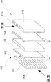
- FIG. 19 is a partially enlarged perspective view schematically showing the structure of a conventional fuel cell.
- the fuel cell 100 includes a positive electrode (air electrode) 102 and a negative electrode (fuel electrode) 104, and an ion is interposed between the positive electrode 102 and the negative electrode 104.
- An electrolyte 106 that can pass through is disposed.
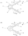
- the positive electrode 102 is composed of a carbon electrode 102a and a platinum catalyst 102b as shown in FIG. 20 (A), which is an enlarged view of part A in FIG.
- the negative electrode 104 is composed of a carbon electrode 104a and a platinum catalyst 104b, as shown in FIG. 20B, which is an enlarged view of part B of FIG.
- the positive electrode 102 and the negative electrode 104 have a structure that allows gas to pass therethrough, and oxygen and hydrogen necessary for the reaction pass therethrough.
- a positive electrode separator 108 is disposed outside the positive electrode 102, and an air supply groove for supplying air to the positive electrode 102 is provided on the positive electrode 102 side of the positive electrode separator 108. 108a is formed.
- a negative electrode separator 110 is disposed outside the negative electrode 104, and an oxygen supply groove for supplying oxygen to the negative electrode 104 is provided on the negative electrode 104 side of the negative electrode separator 110. 110a is formed.
- the positive electrode separator 108, the positive electrode 102, the electrolyte 106, the negative electrode 104, and the negative electrode separator 110 constitute a cell 112.
- the fuel cell 100 is configured by stacking a large number of cells 112 to form a stack structure.
- Patent Document 1 Japanese Patent No. 36822464 discloses a seal structure in which a seal material is disposed between a cell frame frame and a cell.
- Patent Document 1 a total of four seal grooves of an inner seal groove and an outer seal groove are formed on both surfaces of the upper and lower cell frame frames, and a total of four O-rings are formed in these seal grooves. It is equipped with a sealing material. That is, a total of 8 seal members are mounted in a total of 8 seal grooves in the upper and lower cell frame frames.
- the present invention can seal between thin plate members with a thinner and fewer number of sealing materials, and can reduce the size and weight of the device itself used, and can also be assembled.
- An object is to provide a sealing member for a thin plate member that is easy and can be reduced in cost.
- a thin plate member such as a cell of a secondary battery such as a redox flow battery, a fuel battery, or a lead storage battery
- a sealing property is also improved.
- Thin sheet material seal that is good, can be made compact and lightweight, can be assembled easily, can be reduced in cost, can have a large number of stacked cells, and can improve battery capacity.
- the purpose is to provide materials.
- the sealing material for a thin plate member of the present invention is An annular seal member for a thin plate member for sealing between thin plate members, A side seal body disposed on a side of the thin plate member; A pair of leg seal portions that are bifurcated from the side seal body portion and are respectively disposed on the front and back surfaces of the thin plate member; It is characterized by providing.
- the side seal main body portion disposed on the side portion of the thin plate member can seal between the side seal main body portion and the mating member, thereby sealing the side portion of the thin plate member. Accordingly, a single seal for a thin plate member can ensure a double seal of a seal by a pair of leg seal portions and a seal by a side seal main body portion.
- the sealing performance is extremely good, and it is possible to seal between thin plate members with a thinner and fewer number of sealing materials, making it possible to reduce the size and weight of the equipment itself and to assemble it easily. And the sealing material for thin plate members which can also reduce cost can be provided.
- the thin plate member sealing material when the thin plate member sealing material is applied to a thin plate member such as a cell of a secondary battery such as a redox flow battery, a fuel cell, or a lead storage battery, the electrolyte solution of the cell is vertically moved by the pair of leg seal portions. It is possible to prevent leakage between the cells, and it is possible to prevent the cell electrolyte from leaking from the side portion to the outside by the side seal body portion.
- the sealing property is good, the device itself can be made compact and light, the assembly is easy, the cost can be reduced, and the cell It is possible to provide a sealing member for a thin plate member that can increase the number of stacked layers and improve battery capacity.
- the side seal main body portion is disposed on the side portion of the thin plate member, and the pair of leg seal portions branched in a bifurcated manner are disposed on the front and back surfaces of the thin plate member, whereby the thin plate member is disposed on the side portion of the thin plate member.
- the sealing material can be easily mounted, and the thin plate member in the mounted state can be handled as a part, and the operability during assembly is excellent.
- the sealing material for a thin plate member of the present invention is The side seal main body part is formed with a main body side pressure seal projecting projecting part projecting outward in the thickness direction on at least one side of the front and back surfaces.
- the sealing material for a thin plate member of the present invention is
- the main-body-side pressure-contact seal projecting portion is composed of a plurality of main-body-side pressure-contact seal projecting portions arranged at a predetermined interval in the radial direction.
- the sealing material for a thin plate member of the present invention is The position of the projecting portion on the main body side pressure contact seal is formed at a position that matches on the front and back surfaces. In this way, if the position of the main body side pressure seal projecting portion is formed at a position that matches the front and back surfaces, the side portion of the thin plate member can be more reliably sealed.
- the sealing material for a thin plate member of the present invention is At least one of the leg seal portions is formed with a leg-side pressure-contact seal portion having an increased thickness.
- the leg-side pressure contact seal portion in which the thickness of the leg seal portion is increased is formed, the thin plate member is laminated between the front and back surfaces of the thin plate member and the mating member, for example, when thin plate members are laminated. It is possible to more reliably seal between the members.
- the leg-side pressure contact seal portion is composed of a plurality of leg-side pressure contact seal portions arranged at a predetermined interval in the branch direction.
- the sealing material for a thin plate member of the present invention is The position of the leg-side pressure contact seal portion is formed at a position that coincides with the pair of leg seal portions. In this way, if the position of the leg-side pressure contact seal portion is formed at a position that matches the pair of leg seal portions, the sealing performance at the leg-side pressure contact seal portion is improved.
- the sealing material for a thin plate member of the present invention is The leg seal portion has a bent portion formed by protruding a curved portion outward.
- leg seal portion has a bent portion with a curved portion protruding outward, when the thin plate member is sandwiched, the compression load on the thin plate member is reduced and friction with the thin plate member is required. It can be prevented from becoming too large. As a result, when the thin plate member undergoes thermal expansion or contraction, the leg seal portion can be made to follow and behave.
- the sealing material for a thin plate member of the present invention is The side seal main body portion has a curved surface portion at a side end portion. In this way, when the side end portion of the side seal main body portion is formed in a curved shape (curved surface portion), for example, the thin plate member can be sandwiched and the sliding resistance when being housed in the frame frame can be reduced.
- the sealing material for a thin plate member of the present invention is The thin plate member is a battery member. Thus, if it is a battery member, between cells can be sealed reliably.
- the pair of leg seal portions that are bifurcated and are respectively disposed on the front and back surfaces of the thin plate member, for example, when the thin plate member is laminated between the front and back surfaces of the thin plate member and the mating member. Can seal between thin plate members.
- the side seal main body portion disposed on the side portion of the thin plate member can seal between the side seal main body portion and the mating member, thereby sealing the side portion of the thin plate member. Accordingly, a single seal for a thin plate member can ensure a double seal of a seal by a pair of leg seal portions and a seal by a side seal main body portion.
- the sealing performance is extremely good, and it is possible to seal between thin plate members with a thinner and fewer number of sealing materials, making it possible to reduce the size and weight of the equipment itself and to assemble it easily. And the sealing material for thin plate members which can also reduce cost can be provided.
- the thin plate member sealing material when the thin plate member sealing material is applied to a thin plate member such as a cell of a secondary battery such as a redox flow battery, a fuel cell, or a lead storage battery, the electrolyte solution of the cell is vertically moved by the pair of leg seal portions. It is possible to prevent leakage between the cells, and it is possible to prevent the cell electrolyte from leaking from the side portion to the outside by the side seal body portion.
- the sealing property is good, the device itself can be made compact and light, the assembly is easy, the cost can be reduced, and the cell It is possible to provide a sealing member for a thin plate member that can increase the number of stacked layers and improve battery capacity.
- the side seal main body portion is disposed on the side portion of the thin plate member, and the pair of leg seal portions branched in a bifurcated manner are disposed on the front and back surfaces of the thin plate member, whereby the thin plate member is disposed on the side portion of the thin plate member.
- the sealing material can be easily mounted, and the thin plate member in the mounted state can be handled as a part, and the operability during assembly is excellent.
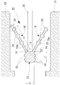
- FIG. 1 is a partially enlarged cross-sectional view showing an embodiment in which the sealing member for a thin plate member of the present invention is applied to a cell of a secondary battery such as a redox flow battery as a thin plate member as a mounted member.
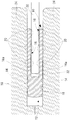
- FIG. 2 is a partially enlarged cross-sectional view showing a compressed state of the sealing member for a thin plate member of FIG.
- FIG. 3 is a top view of the sealing member for a thin plate member of the present invention.
- FIG. 4 is a cross-sectional view of a thin plate member sealing material according to another embodiment of the present invention.
- FIG. 5 is a cross-sectional view of a thin plate member sealing material according to another embodiment of the present invention.
- FIG. 6 is a cross-sectional view of a sealing member for a thin plate member according to another embodiment of the present invention.
- FIG. 7 is a cross-sectional view of a sealing member for a thin plate member according to another embodiment of the present invention.
- FIG. 8 is a cross-sectional view of a sealing member for a thin plate member according to another embodiment of the present invention.
- FIG. 9 is a cross-sectional view of a thin plate member sealing material according to another embodiment of the present invention.
- FIG. 10 is a sectional view of a sealing member for a thin plate member according to another embodiment of the present invention.
- FIG. 11 is a cross-sectional view of a thin plate member sealing material according to another embodiment of the present invention.
- FIG. 12 is a cross-sectional view of a thin plate member sealing material according to another embodiment of the present invention.
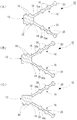
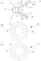
- 13A is a cross-sectional view of a thin plate member sealing material of another embodiment of the present invention
- FIG. 13B is a top view of a thin plate member sealing material of another embodiment of the present invention
- FIG. (C) is a top view of a sealing member for a thin plate member according to another embodiment of the present invention.
- FIG. 14 is a cross-sectional view of a thin plate member sealing material according to another embodiment of the invention.
- FIG. 15 is a sectional view of a sealing member for a thin plate member according to another embodiment of the invention.
- FIG. 16 is a cross-sectional view of a thin plate member sealing material according to another embodiment of the invention.
- FIG. 17 is a cross-sectional view of a thin plate member sealing material according to another embodiment of the invention.
- FIG. 18 is a cross-sectional view of a thin plate member sealing material according to another embodiment of the invention.
- FIG. 19 is a partially enlarged perspective view schematically showing the structure of a conventional fuel cell.
- 20A is an enlarged view of a portion A in FIG. 19, and
- FIG. 20B is an enlarged view of a portion B in FIG.
- FIG. 21 is a partially enlarged perspective view schematically showing the structure of a conventional fuel cell.
- FIG. 1 is a partially enlarged cross-sectional view showing an embodiment in which the sealing member for a thin plate member of the present invention is applied to a cell of a secondary battery such as a redox flow battery as a thin plate member as a mounted member.
- FIG. It is a partial expanded sectional view which shows the compression state of the sealing material for 1 thin plate members.
- reference numeral 10 indicates the whole sheet member sealing material of the present invention.
- the sealing member 10 for a thin plate member of the present invention is annular and is a thin plate member that is a mounted member, that is, in this embodiment, the side of the thin plate member 30 made of cells. It is attached to the portion 32 (in this embodiment, the outer peripheral side portion).
- annular shape is a shape that matches the outer shape of the thin plate member 30, and if the thin plate member 30 is a disc shape, it is a circular ring shape, and if the thin plate member 30 is a rectangular shape, FIGS. 3 (A) and 3 (B).
- the shape is a rectangular ring or the like as shown in FIG.
- the configuration of the positive electrode, the positive electrode cell, the negative electrode, the negative electrode cell, and the diaphragm through which ions can be provided in the thin plate member 30 made of cells is omitted.
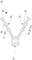
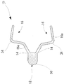
- the thin plate member sealing material 10 includes a side seal body 12 having a substantially rectangular cross section as shown in FIG. A pair of lip-shaped leg seal portions that are bifurcated from both ends 14 in the thickness direction of the end portion on the inner peripheral side of the side seal body portion 12 and are respectively disposed on the front and back surfaces of the thin plate member 30. 16 is extended.
- these leg seal portions 16 can be appropriately changed according to the thickness of the thin plate member 30.
- these leg seal portions 16 have a shape opened by a predetermined angle ⁇ . This is the dimension of the thin plate member seal material 10. Is small, the leg seal portion 16 is difficult to be removed from the mold, so that the shape is designed for easy removal from the mold. Therefore, the angle ⁇ is not particularly limited, and may be appropriately changed according to the size of the thin plate member sealing material 10.
- the thickness L4 of the portion 12 can be appropriately changed according to the type and size of the thin plate member 30 and is not particularly limited.
- the thickness L4 is set as follows. It is desirable to do. -About L1 It is preferable to set L1 ⁇ L3 ⁇ 2 + thickness of the thin plate member 30. Further, it is desirable that L1 is 0.5 to 2 times L4.
- L2 is preferably 1.5 mm to 5.0 mm, and the total of the upper and lower leg seal portions 16 is preferably 5 mm.
- -About L3 It is desirable to be 0.2 mm to 1.0 mm, more preferably 0.25 mm to 1.0 mm. However, it may be appropriately selected depending on the thickness of the thin plate member 30, and the thinner one is preferable.
- leg seal portion 16 has a length of one third of L2, and even one leg-side pressure contact seal portion 20 is possible, and the leg seal portion 16 has one third of L2. It is also possible for the length to be two and the leg-side pressure contact seal portion 20 to be two.
- the side seal main body 12 is formed with a main body side press-contact seal projecting portion 18 projecting outward in the thickness direction on the front and back surfaces. That is, in the case of this embodiment, the main body side pressure seal projecting portions 18 are composed of a plurality of semicircular main body side pressure seal seal projecting portions 18 that are spaced apart from each other in the radial direction. ing.
- main body side press contact seal projecting portions 18 on each of the front and back surfaces that is, a total of four main body side press contact seal projecting portions 18 in total are formed.
- the number of the main-body-side pressure-contact seal projecting portions 18, the separation positions, the projecting dimensions, and the like are not limited, and can be appropriately changed according to the sealing performance, the type and dimensions of the thin plate member 30, and the like.
- the leg seal portion 16 is formed with a leg-side pressure contact seal portion 20 having a thickness greater than that of the main body portion 16a, and in this embodiment, a plurality of semicircular cross-section leg-side pressure contact seal portions 20 are formed. ing. That is, in the case of this embodiment, the leg-side pressure contact seal portion 20 is composed of a plurality of leg-side pressure contact seal portions 20 arranged at a predetermined interval in the branch direction.
- leg-side pressure contact seal portions 20 are formed on the leg seal portions 16 on the front and back surfaces, respectively, including the three leg-side pressure contact seal portions 20 and the front and back surfaces.
- the number of leg-side pressure contact seal portions 20, the separation position, the ratio with the thickness of the main body portion 16a, etc. are not limited, and are appropriately changed according to the sealing property, the type and size of the thin plate member 30, and the like. be able to.
- the material for the sealing member 10 for a thin plate member of the present invention is not particularly limited, and may be made of, for example, a synthetic resin or rubber as long as it has a certain degree of elasticity and can provide a sealing property. it can.
- rubber as an elastic member, and as the rubber, natural rubber, for example, ethylene / propylene rubber such as EPM and EPDM, and synthetic rubber such as fluorine rubber can be used.
- natural rubber for example, ethylene / propylene rubber such as EPM and EPDM
- synthetic rubber such as fluorine rubber
- synthetic resin for example, fluorine resin, polyimide resin, polyamideimide resin, polyetherimide resin, polyamideimide resin, polyphenylene sulfide resin, polybenzimidazole resin, polyether ketone resin, and the like can be used.
- the pair of lip-shaped leg seal portions 16 are disposed on the front and back surfaces of the thin plate member 30 by being attached to the side portions 32 of the thin plate member 30.
- a cell frame sandwiching body is formed by sandwiching between a pair of frame frames 24, and a plurality of cell frame sandwiching bodies are appropriately stacked, and a redox flow battery is assembled (not shown). It is like that.
- the thin plate member 30 can be sealed between the front and back surfaces of the thin plate member and the mating member, for example, when the thin plate member 30 is laminated.
- the leg-side pressure contact seal portion 20 in which the thickness of the leg seal portion 16 is increased so that, for example, between the front and back surfaces of the thin plate member 30 and the mating member, When the thin plate members 30 are stacked, the space between the thin plate members 30 can be more reliably sealed.
- the side seal main body portion 12 disposed on the side portion 32 of the thin plate member 30 seals between the side seal main body portion 12 and the mating member, so that the thin plate member 30 The side 32 can be sealed.
- the side portion 32 of the thin plate member 30 can be more reliably sealed by the main body side press-contact seal projecting portion 18 of the side seal main body portion 12. Accordingly, a single seal member 10 for a thin plate member can ensure a double seal of the seal by the pair of leg seal portions 16 and the seal by the side seal main body portion 12.
- the sealing performance is extremely good, and it is possible to satisfactorily seal between the thin plate members 30 with a thinner and fewer number of sealing materials, making it possible to reduce the size and weight of the device itself and to assemble it. It is possible to provide a sealing material for a thin plate member that is easy and can be reduced in cost.
- a pair of leg seal portions 16 can prevent the cell electrolyte from leaking between the upper and lower cells, and the side seal body 12 can prevent the cell electrolyte from leaking from the side to the outside.
- the sealing property is good, the device itself can be made compact and light, the assembly is easy, the cost can be reduced, and the cells are stacked. It is possible to provide a sealing member for a thin plate member that can increase the number of sheets and improve the battery capacity.
- the side seal main body 12 is disposed on the side portion 32 of the thin plate member 30, and the pair of leg seal portions 16 that are bifurcated are disposed on the front and back surfaces of the thin plate member 30.
- the thin plate member sealing material 10 can be easily mounted on the side portion 32, and the mounted thin plate member can be handled as a component, which is excellent in operability during assembly.
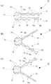
- the positions of the main body side pressure seal projecting portions 18 are formed at positions that coincide with each other on the front and back surfaces. However, as shown in FIG. It is also possible to form the portion 18 at different positions on the front and back surfaces. Further, in this embodiment, the main body side pressure seal projecting portions 18 are formed on the front and back surfaces, but as shown in FIGS. 5B and 5C, the main body side pressure seal projecting portions are provided only on one side of the front and back surfaces. The portion 18 can also be formed.
- the shape of the main body side pressure contact seal projecting portion 18 is a semicircular cross section, but this shape is not particularly limited.
- this shape is not particularly limited.
- FIG. It can also be set as the shape main body side press-contact seal protrusion part 18, and can be changed suitably.
- the side seal body 12 has a rectangular cross section
- the main body pressure contact seal projection 18 has a rectangular cross section.
- the main body part 12 it is also possible to make the main body part 12 have a circular cross section so as to give a sealing property thereto.
- the main body side press-contact seal projecting portions 18 all have the same dimensions (thickness), but as shown in FIG. 7A, the outer diameter from the inner diameter side of the side seal main body portion 12 is increased.
- the size of the main body side pressure seal projecting portion 18 gradually decreases toward the side, and the main body side pressure seal seal projecting portion 18 on the outer diameter side functions as an auxiliary seal to increase the sealing performance. It is also possible.
- the size of the main body side press-contact seal projecting portion 18 gradually increases from the inner diameter side to the outer diameter side of the side seal main body portion 12. In this way, it is possible to increase the sealing performance.
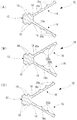
- the positions of the leg-side pressure contact seal portions 20 are formed at positions that coincide with each other on the leg seal portions 16 on the front and back surfaces. However, as shown in FIG. It is also possible to form the positions of the side pressure contact seal portions 20 at different positions in the leg seal portions 16 on the front and back surfaces.
- leg-side pressure contact seal portion 20 is provided on the leg seal portion 16 on the front and back surfaces, but as shown in FIGS. 8B and 8C, one leg seal portion is provided. It is also possible to provide the leg-side pressure-contact seal portion 20 only at 16.
- the shape of the leg-side pressure contact seal portion 20 is a semicircular cross section, but this shape is not particularly limited and is thicker than the thickness of the main body portion 16a of the leg seal portion 16.
- the leg-side pressure contact seal portion 20 having a rectangular cross section can be used, and can be changed as appropriate.
- the leg-side pressure contact seal portion 20 is composed of an outer protrusion portion 20a and an inner protrusion portion 20b that protrude from the front and rear surfaces of the leg seal portion 16.
- the outer protruding portion 20a can be used, or as shown in FIG. 10 (B), only the inner protruding portion 20b can be used.
- FIG. 5 it is possible to combine the outer projecting portion 20a and the inner projecting portion 20b.
- only one leg seal portion 16 may be the outer projecting portion 20a.
- only the inner projecting portion 20b may be used.
- leg-side pressure contact seal portions 20 are all the same size (thickness), but as shown in FIG. In order to increase the sealing performance, the size of the leg-side pressure contact seal portion 20 is gradually reduced toward the base, and the leg-side pressure contact seal portion 20 on the base end side functions as an auxiliary seal. Is possible.
- the combination of the leg side pressure contact seal portion 20 is, of course, small in the middle and large in the outer two.
- the size of the leg-side pressure contact seal portion 20 gradually increases from the branching tip of the leg seal portion 16 toward the base end portion. In this way, it is possible to increase the sealing performance.
- the branch lengths of the leg seal portions 16 on the front and back surfaces are the same, but as shown in FIG. 13A, the branch lengths of the leg seal portions 16 on the front and back surfaces are made different. You can also
- the branch length of the leg seal portion 16 may be the same over the entire annular shape of the thin plate member sealing material 10.
- the branch length of the leg seal portion 16 may be different over the entire annular shape of the thin plate member sealing material 10.
- FIG. 14 is a sectional view of a sealing member for a thin plate member of another embodiment of the apparatus of the present invention.
- the thin plate member sealing material 10 has basically the same configuration as the thin plate member sealing material 10 shown in FIG. 1, and the same reference numerals are given to the same structural members, and the detailed description thereof will be omitted. Description is omitted.
- the leg-side pressure contact seal portion 20 in which the thickness of the leg seal portion 16 is increased is omitted, and the body-side pressure contact seal projecting portion 18 of the side seal body portion 12 is omitted. Is omitted.
- the leg-side pressure contact seal portion 20 in which the thickness of the leg seal portion 16 is increased is omitted as in this embodiment, and the body-side pressure seal of the side seal body portion 12 is omitted. Even if the protruding portion 18 is omitted, a double seal of a seal by the pair of leg seal portions 16 and a seal by the side seal main body portion 12 can be secured.
- FIG. 15 is a sectional view of a sealing member for a thin plate member of another embodiment of the apparatus of the present invention.
- the thin plate member sealing material 10 has basically the same configuration as the thin plate member sealing material 10 shown in FIG. 1, and the same reference numerals are given to the same structural members, and the detailed description thereof will be omitted. Description is omitted.
- the leg-side pressure contact seal portion 20 in which the thickness of the leg seal portion 16 is increased is omitted.
- the seal by the pair of leg seal portions 16 and A double seal with the seal by the side seal body 12 can be ensured.
- FIG. 16 is a sectional view of a sealing member for a thin plate member of another embodiment of the apparatus of the present invention.
- the thin plate member sealing material 10 has basically the same configuration as the thin plate member sealing material 10 shown in FIG. 1, and the same reference numerals are given to the same structural members, and the detailed description thereof will be omitted. Description is omitted.
- the main body side pressure seal seal projecting portion 18 of the side seal main body portion 12 is omitted. In this way, depending on the use conditions, even if the main body side press-contact seal protruding portion 18 of the side seal main body portion 12 is omitted as in this embodiment, the seal by the pair of leg seal portions 16 and the side seal A double seal with the seal by the main body 12 can be ensured.
- FIG. 17 is a cross-sectional view of a thin plate member sealing material of another embodiment of the apparatus of the present invention.
- the thin plate member sealing material 10 has basically the same configuration as the thin plate member sealing material 10 shown in FIG. 1, and the same reference numerals are given to the same structural members, and the detailed description thereof will be omitted. Description is omitted.
- the leg-side pressure contact seal portion 20 in which the thickness of the leg seal portion 16 is increased is omitted, and a dog-shaped bent portion 34 is provided in the middle of the leg seal portion 16.
- one main body side pressure seal seal projecting portion 18 of the side seal main body portion 12 is provided on the upper and lower sides.
- the compression load applied to the thin plate member 30 may be reduced. While reducing, it can prevent that the friction with the thin plate member 30 becomes too large more than necessary. As a result, when the thin plate member 30 is thermally expanded or contracted, the leg seal portion 16 can be made to follow and behave.
- FIG. 18 is a cross-sectional view of a thin plate member sealing material of another embodiment of the apparatus of the present invention.
- the thin plate member sealing material 10 has basically the same configuration as the thin plate member sealing material 10 shown in FIG. 1, and the same reference numerals are given to the same structural members, and the detailed description thereof will be omitted. Description is omitted.
- the leg-side pressure contact seal portion 20 in which the thickness of the leg seal portion 16 is increased is omitted, and a dog-shaped bent portion 34 is provided in the middle of the leg seal portion 16.
- the main body side pressure seal seal projecting portion 18 of the side seal main body portion 12 is omitted, and the side end portion has a curved shape (curved surface portion 36).
- the compression load applied to the thin plate member 30 may be reduced. While reducing, it can prevent that the friction with the thin plate member 30 becomes too large more than necessary. As a result, when the thin plate member 30 is thermally expanded or contracted, the leg seal portion 16 can be made to follow and behave.
- the side end portion of the side seal main body portion 12 into a curved shape (curved surface portion 36), it is possible to reduce the sliding resistance when sandwiching the thin plate member 30 and storing it in the frame frame 24, A double seal of a seal by the pair of leg seal portions 16 and a seal by the side seal main body portion 12 can be secured.
- the present invention is not limited to this.
- the thin plate member sealing material 10 of the present invention is annular, and the thin plate although it attached to the outer peripheral side of the member 30, when the thin plate member 30 has a ring shape, the thin plate member sealing material 10 should be attached to the inner peripheral side of the thin plate member 30. Is also possible.
- the thin plate member sealing material 10 of the present invention is applied to a cell of a secondary battery such as a redox flow battery as the thin plate member 30, but the present invention is not limited to this.
- a secondary battery such as a redox flow battery as the thin plate member 30
- the present invention is not limited to this.
- Various modifications can be made without departing from the object of the present invention, such as being applicable as a sealing member for a thin plate member for sealing between thin plate members.
- the present invention can be applied to, for example, a sealing material for a thin plate member for sealing between a thin plate member such as a redox flow battery, a fuel cell, a cell of a secondary battery such as a lead storage battery, or a filter.
- a sealing material for a thin plate member for sealing between a thin plate member such as a redox flow battery, a fuel cell, a cell of a secondary battery such as a lead storage battery, or a filter.
Landscapes
- Engineering & Computer Science (AREA)
- General Chemical & Material Sciences (AREA)
- General Engineering & Computer Science (AREA)
- Sustainable Development (AREA)
- Sustainable Energy (AREA)
- Chemical & Material Sciences (AREA)
- Chemical Kinetics & Catalysis (AREA)
- Manufacturing & Machinery (AREA)
- Life Sciences & Earth Sciences (AREA)
- Electrochemistry (AREA)
- Mechanical Engineering (AREA)
- Geometry (AREA)
- Physics & Mathematics (AREA)
- Fuel Cell (AREA)
- Gasket Seals (AREA)
- Secondary Cells (AREA)
Abstract
Description
すなわち、図19は、従来の燃料電池の構造を模式的に示す部分拡大斜視図である。
また、正極電極102の外側には、正極電極用セパレーター108が配置されており、この正極電極用セパレーター108の正極電極102の側には、空気を正極電極102に供給するための空気供給用溝108aが形成されている。
図21に示したように、燃料電池100は、このセル112を多数積層してスタック構造とすることによって構成されている。
本発明は、このような現状に鑑み、より薄く、数の少ないシール材で、薄板部材の間を良好にシールすることができ、使用される装置自体のコンパクト化、軽量化が図れ、組み立ても容易であって、コストも低減可能な薄板部材用シール材を提供することを目的とする。
本発明の薄板部材用シール材は、
薄板部材の間をシールするための環状の薄板部材用シール材であって、
前記薄板部材の側部に配置される側部シール本体部と、
前記側部シール本体部から二股状に分岐して、前記薄板部材の表裏面にそれぞれ配置される一対の脚シール部と、
を備えることを特徴とする。
従って、1つの薄板部材用シール材で、一対の脚シール部によるシールと、側部シール本体部によるシールとの、二重のシールを確保することができる。
前記側部シール本体部には、表裏面の少なくとも一方側に、厚さ方向外側に突設する本体側圧接シール突設部が形成されていることを特徴とする。
このように構成することによって、側部シール本体部の本体側圧接シール突設部によって、薄板部材の側部をより確実にシールすることができる。
前記本体側圧接シール突設部が、径方向に一定間隔離間して配置された複数の本体側圧接シール突設部から構成されていることを特徴とする。
このように構成することによって、径方向に一定間隔離間して配置された複数の本体側圧接シール突設部により、薄板部材の側部をさらに確実にシールすることができる。
前記本体側圧接シール突設部の位置が、表裏面において合致した位置に形成されていることを特徴とする。
このように本体側圧接シール突設部の位置が、表裏面において合致した位置に形成されていれば、薄板部材の側部をさらに確実にシールすることができる。
前記脚シール部のうち少なくとも一方に、厚さが厚くなった脚部側圧接シール部が形成されていることを特徴とする。
前記脚部側圧接シール部が、分岐方向に一定間隔離間して配置された複数の脚部側圧接シール部から構成されていることを特徴とする。
前記脚部側圧接シール部の位置が、一対の脚シール部において合致した位置に形成されていることを特徴とする。
このように脚部側圧接シール部の位置が、一対の脚シール部において合致した位置に形成されていれば、脚部側圧接シール部でのシール性が向上することになる。
前記脚シール部に、外方に曲部が突出して成る屈曲部を有することを特徴とする。
前記側部シール本体部には、側端部に曲面部を有することを特徴とする。
このように、側部シール本体部の側端部を曲面状の形態(曲面部)とすれば、例えば薄板部材を挟持し、フレーム枠内に収める際における摺動抵抗を下げることができる。
前記薄板部材が、電池用部材であることを特徴とする。
このように電池用部材であれば、セルの間を確実にシールすることができる。
従って、1つの薄板部材用シール材で、一対の脚シール部によるシールと、側部シール本体部によるシールとの、二重のシールを確保することができる。
図1は、本発明の薄板部材用シール材を、被装着部材である薄板部材として、レドックスフロー電池などの二次電池のセルに適用した実施例を示す部分拡大断面図、図2は、図1の薄板部材用シール材の圧縮状態を示す部分拡大断面図である。
図1に示したように、本発明の薄板部材用シール材10は、環状であって、被装着部材である薄板部材、すなわち、この実施例の場合には、セルからなる薄板部材30の側部32(この実施例では、外周側の側部)に装着されるものである。
また、この実施例の場合には、図1に示したように、これらの脚シール部16が、所定の角度α開いた形状となっているが、これは、薄板部材用シール材10の寸法が小さい場合、金型から、脚シール部16が抜けにくいために、金型から抜きやすくするための設計上の形状である。従って、このαの角度は、特に限定されるものではなく、薄板部材用シール材10の寸法に応じて適宜変更すれば良い。
また、図1に示したように、側部シール本体部12の径方向の幅L1、脚シール部16の分岐長さL2、脚シール部16の本体部16aの厚さL3、側部シール本体部12の厚さL4としては、薄板部材30の種類、寸法などに応じて適宜変更することができ、特に限定されるものではないが、例えば、シール性を考慮すれば、下記のように設定するのが望ましい。
・L1について
L1≧L3×2+薄板部材30の厚さとするのが好ましい。
また、L1をL4の0.5~2倍とするのが望ましい。
1.5mm~5.0mmとするのが好ましく、また、上下の脚シール部16の合計で、5mmとするのが望ましい。
・L3について
0.2mm~1.0mm、より好ましくは、0.25mm~1.0mmとするのが望ましい。但し、薄板部材30の厚さによって、適宜選択すればよく、薄い方が好ましい。
・L4について
L4=薄板部材30の厚さ+L3×2とするのが望ましい。
この場合、本体側圧接シール突設部18の個数、離間位置、突設寸法などは限定されるものではなく、シール性、薄板部材30の種類、寸法などに応じて適宜変更することができる。
この場合、脚部側圧接シール部20の個数、離間位置、本体部16aの厚さとの比などは限定されるものではなく、シール性、薄板部材30の種類、寸法などに応じて適宜変更することができる。
従って、1つの薄板部材用シール材10で、一対の脚シール部16によるシールと、側部シール本体部12によるシールとの、二重のシールを確保することができる。
これとは逆に、図12(B)に示したように、脚シール部16の分岐方向の先端から基端部に向けて、徐々に脚部側圧接シール部20の大きさが大きくなるようにして、シール性を増大することも可能である。
この薄板部材用シール材10は、図1に示した薄板部材用シール材10と基本的には同様な構成であり、同一の構成部材には、同一の参照番号を付して、その詳細な説明を省略する。
この薄板部材用シール材10は、図1に示した薄板部材用シール材10と基本的には同様な構成であり、同一の構成部材には、同一の参照番号を付して、その詳細な説明を省略する。
このように、使用条件によっては、この実施例のように、脚シール部16の厚さが厚くなった脚部側圧接シール部20を省略しても、一対の脚シール部16によるシールと、側部シール本体部12によるシールとの、二重のシールを確保することができる。
この薄板部材用シール材10は、図1に示した薄板部材用シール材10と基本的には同様な構成であり、同一の構成部材には、同一の参照番号を付して、その詳細な説明を省略する。
このように、使用条件によっては、この実施例のように、側部シール本体部12の本体側圧接シール突設部18を省略しても、一対の脚シール部16によるシールと、側部シール本体部12によるシールとの、二重のシールを確保することができる。
この薄板部材用シール材10は、図1に示した薄板部材用シール材10と基本的には同様な構成であり、同一の構成部材には、同一の参照番号を付して、その詳細な説明を省略する。
この薄板部材用シール材10は、図1に示した薄板部材用シール材10と基本的には同様な構成であり、同一の構成部材には、同一の参照番号を付して、その詳細な説明を省略する。
12 側部シール本体部
14 両端
16 脚シール部
16a 本体部
18 本体側圧接シール突設部
20 脚部側圧接シール部
20a 外側突設部
20b 内側突設部
24 フレーム枠
30 薄板部材
32 側部
34 屈曲部
36 曲面部
100 燃料電池
102 正極電極
104 正極セル
106 負極電極
108 負極セル
110 隔膜
112 セル
114 セルフレーム枠
118 内側シール溝
120 外側シール溝
122 シール材
Claims (10)
- 薄板部材の間をシールするための環状の薄板部材用シール材であって、
前記薄板部材の側部に配置される側部シール本体部と、
前記側部シール本体部から二股状に分岐して、前記薄板部材の表裏面にそれぞれ配置される一対の脚シール部と、
を備えることを特徴とする薄板部材用シール材。 - 前記側部シール本体部には、表裏面の少なくとも一方側に、厚さ方向外側に突設する本体側圧接シール突設部が形成されていることを特徴とする請求項1に記載の薄板部材用シール材。
- 前記本体側圧接シール突設部が、径方向に一定間隔離間して配置された複数の本体側圧接シール突設部から構成されていることを特徴とする請求項2に記載の薄板部材用シール材。
- 前記本体側圧接シール突設部の位置が、表裏面において合致した位置に形成されていることを特徴とする請求項2または3に記載の薄板部材用シール材。
- 前記脚シール部のうち少なくとも一方に、厚さが厚くなった脚部側圧接シール部が形成されていることを特徴とする請求項1~4のいずれかに記載の薄板部材用シール材。
- 前記脚部側圧接シール部が、分岐方向に一定間隔離間して配置された複数の脚部側圧接シール部から構成されていることを特徴とする請求項5に記載の薄板部材用シール材。
- 前記脚部側圧接シール部の位置が、一対の脚シール部において合致した位置に形成されていることを特徴とする請求項5または6に記載の薄板部材用シール材。
- 前記脚シール部に、外方に曲部が突出して成る屈曲部を有することを特徴とする請求項1~7のいずれかに記載の薄板部材用シール材。
- 前記側部シール本体部には、側端部に曲面部を有することを特徴とする請求項1~8のいずれかに記載の薄板部材用シール材。
- 前記薄板部材が、電池用部材であることを特徴とする請求項1~9のいずれかに記載の薄板部材用シール材。
Priority Applications (6)
| Application Number | Priority Date | Filing Date | Title |
|---|---|---|---|
| KR1020137027234A KR101859248B1 (ko) | 2011-03-31 | 2012-03-30 | 박판 부재용 실링재 |
| CA2831749A CA2831749C (en) | 2011-03-31 | 2012-03-30 | Sealing material for thin plate member |
| US13/982,875 US9077010B2 (en) | 2011-03-31 | 2012-03-30 | Sealing material for thin plate member |
| AU2012233356A AU2012233356A1 (en) | 2011-03-31 | 2012-03-30 | Seal material for thin plate members |
| EP12765425.9A EP2693087B1 (en) | 2011-03-31 | 2012-03-30 | Seal material for thin plate members |
| CN201280015205.6A CN103443513B (zh) | 2011-03-31 | 2012-03-30 | 薄板部件用密封件 |
Applications Claiming Priority (4)
| Application Number | Priority Date | Filing Date | Title |
|---|---|---|---|
| JP2011-078007 | 2011-03-31 | ||
| JP2011078007 | 2011-03-31 | ||
| JP2012057048A JP5427263B2 (ja) | 2011-03-31 | 2012-03-14 | 薄板部材用シール材 |
| JP2012-057048 | 2012-03-14 |
Publications (1)
| Publication Number | Publication Date |
|---|---|
| WO2012133738A1 true WO2012133738A1 (ja) | 2012-10-04 |
Family
ID=46931436
Family Applications (1)
| Application Number | Title | Priority Date | Filing Date |
|---|---|---|---|
| PCT/JP2012/058522 Ceased WO2012133738A1 (ja) | 2011-03-31 | 2012-03-30 | 薄板部材用シール材 |
Country Status (9)
| Country | Link |
|---|---|
| US (1) | US9077010B2 (ja) |
| EP (1) | EP2693087B1 (ja) |
| JP (1) | JP5427263B2 (ja) |
| KR (1) | KR101859248B1 (ja) |
| CN (1) | CN103443513B (ja) |
| AU (1) | AU2012233356A1 (ja) |
| CA (1) | CA2831749C (ja) |
| TW (1) | TWI484109B (ja) |
| WO (1) | WO2012133738A1 (ja) |
Cited By (1)
| Publication number | Priority date | Publication date | Assignee | Title |
|---|---|---|---|---|
| JP2017134954A (ja) * | 2016-01-26 | 2017-08-03 | 住友電気工業株式会社 | 電池、及びシール材 |
Families Citing this family (15)
| Publication number | Priority date | Publication date | Assignee | Title |
|---|---|---|---|---|
| JP5477672B2 (ja) | 2011-03-31 | 2014-04-23 | 住友電気工業株式会社 | 電解液流通型電池用セルフレーム、電解液流通型電池用セルスタック、及び電解液流通型電池 |
| GB2501774A (en) * | 2012-05-04 | 2013-11-06 | Control Tech Ltd | A sealing element for sealing between planar surfaces |
| JP6152640B2 (ja) * | 2012-12-18 | 2017-06-28 | 株式会社Gsユアサ | 密閉型電池用ゴム製弁体、安全弁装置及びアルカリ蓄電池 |
| US9963795B2 (en) * | 2013-04-30 | 2018-05-08 | Asahi Kasei Kabushiki Kaisha | Gasket and electrolyser |
| JP6247590B2 (ja) * | 2014-05-07 | 2017-12-13 | 旭化成株式会社 | セル積層体および蓄電池 |
| JP6296500B2 (ja) * | 2014-08-22 | 2018-03-20 | 日本バルカー工業株式会社 | 液体漏れ検知ユニット |
| US10588248B1 (en) | 2014-10-24 | 2020-03-10 | L-3 Communications Corp. | Radial EMI and environmental gasket |
| AU2020323283B2 (en) * | 2019-07-30 | 2023-09-14 | Asahi Kasei Kabushiki Kaisha | Alkaline water electrolytic cell |
| CN111473117B (zh) * | 2020-05-14 | 2022-11-18 | Abb瑞士股份有限公司 | 环形密封件和机器人 |
| CN112908210B (zh) * | 2021-01-27 | 2023-05-09 | 浙江经贸职业技术学院 | 一种教育用教育宣传设备 |
| DE102021105597A1 (de) | 2021-03-09 | 2022-09-15 | Schaeffler Technologies AG & Co. KG | Elektrodenmodul für eine Redox-Flow-Zelle und Verfahren zu seiner Montage sowie Redox-Flow-Zelle |
| DE102021111054B3 (de) * | 2021-04-29 | 2022-05-12 | Schaeffler Technologies AG & Co. KG | Redox-Flow-Zelle und Verfahren zu ihrer Montage sowie Redox-Flow-Batterie |
| DE102022205757A1 (de) * | 2022-06-07 | 2023-12-07 | Robert Bosch Gesellschaft mit beschränkter Haftung | Dichtungselement |
| DE102022119436B4 (de) * | 2022-08-03 | 2026-03-05 | Schaeffler Technologies AG & Co. KG | Redox-Flusszelle |
| WO2025249562A1 (ja) * | 2024-05-31 | 2025-12-04 | Nok株式会社 | 水電解装置、ガスケット、及びガスケット装置 |
Citations (7)
| Publication number | Priority date | Publication date | Assignee | Title |
|---|---|---|---|---|
| JPS6191664U (ja) * | 1984-11-20 | 1986-06-13 | ||
| JPH03107674A (ja) * | 1989-09-21 | 1991-05-08 | Nippon Valqua Ind Ltd | フッ素樹脂被覆ガスケットとその製造方法 |
| JPH0750169A (ja) * | 1990-01-09 | 1995-02-21 | Gebr Sulzer Ag | 燃料セルバッテリ |
| JP2003056704A (ja) * | 2001-03-09 | 2003-02-26 | Nok Corp | ガスケット |
| JP2004245341A (ja) * | 2003-02-14 | 2004-09-02 | Nok Corp | ガスケット |
| JP3682244B2 (ja) | 2001-06-12 | 2005-08-10 | 住友電気工業株式会社 | レドックスフロー電池用セルフレーム及びレドックスフロー電池 |
| JP2011003453A (ja) * | 2009-06-19 | 2011-01-06 | Nok Corp | 燃料電池の密封構造 |
Family Cites Families (16)
| Publication number | Priority date | Publication date | Assignee | Title |
|---|---|---|---|---|
| US4072245A (en) * | 1976-07-16 | 1978-02-07 | Stant Manufacturing Company, Inc. | Filler neck cap with O-ring seal |
| NL164945C (nl) * | 1977-11-23 | 1981-02-16 | Vredestein Nv | Afdichtingsprofiel voor een uit segmenten opgebouwde tunnel. |
| GB2189850A (en) * | 1986-05-02 | 1987-11-04 | Michael John Caswell Tozer | Metallic sealing rings |
| GB2189851A (en) * | 1986-05-02 | 1987-11-04 | Michael John Caswell Tozer | Metallic sealing rings |
| FR2627835B1 (fr) * | 1988-02-26 | 1991-05-17 | Hutchinson | Coulisse d'etancheite de glace mobile, notamment de vitre de vehicule automobile |
| JP2555789B2 (ja) * | 1991-03-26 | 1996-11-20 | 豊田合成株式会社 | フユーエルキヤツプ |
| US6161841A (en) * | 1999-03-22 | 2000-12-19 | Shaw; Richard J. | Vehicle O ring fuel cap gasket |
| WO2002043172A1 (en) | 2000-11-21 | 2002-05-30 | Nok Corporation | Constituent part for fuel cell |
| JP4928681B2 (ja) * | 2001-06-07 | 2012-05-09 | 三菱重工業株式会社 | メタルパッキン |
| US20050242571A1 (en) * | 2002-12-06 | 2005-11-03 | Jon Houghton | Pipe fitting with composite gasket assembly |
| KR100501682B1 (ko) | 2003-06-20 | 2005-07-18 | 현대자동차주식회사 | 연료전지용 가스켓 및 그 제조방법 |
| WO2007007612A1 (ja) * | 2005-07-07 | 2007-01-18 | Nok Corporation | ガスケット |
| US7481028B2 (en) * | 2006-07-17 | 2009-01-27 | Anderson Corporation | Mulling and sealing system for compound fenestration units |
| JP5151241B2 (ja) * | 2007-05-10 | 2013-02-27 | Nok株式会社 | 密封構造 |
| US7828302B2 (en) * | 2007-08-15 | 2010-11-09 | Federal-Mogul Corporation | Lateral sealing gasket and method |
| JP5224035B2 (ja) * | 2008-02-12 | 2013-07-03 | Nok株式会社 | シール構造体の製造方法 |
-
2012
- 2012-03-14 JP JP2012057048A patent/JP5427263B2/ja active Active
- 2012-03-30 WO PCT/JP2012/058522 patent/WO2012133738A1/ja not_active Ceased
- 2012-03-30 TW TW101111323A patent/TWI484109B/zh active
- 2012-03-30 KR KR1020137027234A patent/KR101859248B1/ko active Active
- 2012-03-30 EP EP12765425.9A patent/EP2693087B1/en not_active Not-in-force
- 2012-03-30 CA CA2831749A patent/CA2831749C/en active Active
- 2012-03-30 AU AU2012233356A patent/AU2012233356A1/en not_active Abandoned
- 2012-03-30 CN CN201280015205.6A patent/CN103443513B/zh active Active
- 2012-03-30 US US13/982,875 patent/US9077010B2/en active Active
Patent Citations (7)
| Publication number | Priority date | Publication date | Assignee | Title |
|---|---|---|---|---|
| JPS6191664U (ja) * | 1984-11-20 | 1986-06-13 | ||
| JPH03107674A (ja) * | 1989-09-21 | 1991-05-08 | Nippon Valqua Ind Ltd | フッ素樹脂被覆ガスケットとその製造方法 |
| JPH0750169A (ja) * | 1990-01-09 | 1995-02-21 | Gebr Sulzer Ag | 燃料セルバッテリ |
| JP2003056704A (ja) * | 2001-03-09 | 2003-02-26 | Nok Corp | ガスケット |
| JP3682244B2 (ja) | 2001-06-12 | 2005-08-10 | 住友電気工業株式会社 | レドックスフロー電池用セルフレーム及びレドックスフロー電池 |
| JP2004245341A (ja) * | 2003-02-14 | 2004-09-02 | Nok Corp | ガスケット |
| JP2011003453A (ja) * | 2009-06-19 | 2011-01-06 | Nok Corp | 燃料電池の密封構造 |
Non-Patent Citations (1)
| Title |
|---|
| See also references of EP2693087A4 * |
Cited By (2)
| Publication number | Priority date | Publication date | Assignee | Title |
|---|---|---|---|---|
| JP2017134954A (ja) * | 2016-01-26 | 2017-08-03 | 住友電気工業株式会社 | 電池、及びシール材 |
| WO2017130697A1 (ja) * | 2016-01-26 | 2017-08-03 | 住友電気工業株式会社 | 電池、及びシール材 |
Also Published As
| Publication number | Publication date |
|---|---|
| US20130307227A1 (en) | 2013-11-21 |
| JP5427263B2 (ja) | 2014-02-26 |
| EP2693087A4 (en) | 2014-10-08 |
| CA2831749C (en) | 2018-05-29 |
| CA2831749A1 (en) | 2012-10-04 |
| JP2012215291A (ja) | 2012-11-08 |
| EP2693087A1 (en) | 2014-02-05 |
| KR20140017610A (ko) | 2014-02-11 |
| KR101859248B1 (ko) | 2018-05-17 |
| CN103443513B (zh) | 2016-05-04 |
| TWI484109B (zh) | 2015-05-11 |
| US9077010B2 (en) | 2015-07-07 |
| CN103443513A (zh) | 2013-12-11 |
| EP2693087B1 (en) | 2015-09-16 |
| AU2012233356A1 (en) | 2013-08-15 |
| TW201307709A (zh) | 2013-02-16 |
Similar Documents
| Publication | Publication Date | Title |
|---|---|---|
| JP5427263B2 (ja) | 薄板部材用シール材 | |
| CN102428599B (zh) | 燃料电池的密封构造 | |
| JPWO2011114811A1 (ja) | 燃料電池セル | |
| US9780400B2 (en) | Fuel cell having an empty space gap between the separator and electrode | |
| US9843063B2 (en) | Fuel cell | |
| JP6150040B2 (ja) | 燃料電池及び燃料電池スタック | |
| CA2476369A1 (en) | Polymer electrolyte fuel cell with a seal feature | |
| JP7344802B2 (ja) | 燃料電池のシール構造 | |
| JP7130610B2 (ja) | 燃料電池用金属セパレータ、接合セパレータ及び発電セル | |
| JP5549578B2 (ja) | 燃料電池 | |
| JP2003147564A (ja) | 固体高分子膜水電解装置におけるスタック構造及び該装置に使用される固体高分子膜 | |
| KR101822246B1 (ko) | 연료전지 스택 | |
| JP2008010350A5 (ja) | ||
| CN104124458B (zh) | 燃料电池 | |
| JP5428923B2 (ja) | 燃料電池用シール構造体 | |
| JP2010015939A (ja) | 燃料電池 | |
| JP6891777B2 (ja) | 燃料電池単セル | |
| JPWO2018011948A1 (ja) | 燃料電池スタック | |
| KR20140020557A (ko) | 연료전지 스택의 탄성 체결장치 | |
| JP2008004448A (ja) | 燃料電池スタック | |
| JP2019140028A (ja) | ガス拡散層一体ガスケット及び燃料電池セル用部材 | |
| JP5802181B2 (ja) | 燃料電池 | |
| JP6544229B2 (ja) | 燃料電池セル | |
| JP2016157601A (ja) | 燃料電池スタック | |
| JP2022166476A (ja) | 燃料電池のセルスタック |
Legal Events
| Date | Code | Title | Description |
|---|---|---|---|
| WWE | Wipo information: entry into national phase |
Ref document number: 201280015205.6 Country of ref document: CN |
|
| 121 | Ep: the epo has been informed by wipo that ep was designated in this application |
Ref document number: 12765425 Country of ref document: EP Kind code of ref document: A1 |
|
| WWE | Wipo information: entry into national phase |
Ref document number: 2012765425 Country of ref document: EP |
|
| WWE | Wipo information: entry into national phase |
Ref document number: 13982875 Country of ref document: US |
|
| ENP | Entry into the national phase |
Ref document number: 2012233356 Country of ref document: AU Date of ref document: 20120330 Kind code of ref document: A |
|
| ENP | Entry into the national phase |
Ref document number: 2831749 Country of ref document: CA |
|
| NENP | Non-entry into the national phase |
Ref country code: DE |
|
| ENP | Entry into the national phase |
Ref document number: 20137027234 Country of ref document: KR Kind code of ref document: A |