WO2012137319A1 - 集卵機 - Google Patents
集卵機 Download PDFInfo
- Publication number
- WO2012137319A1 WO2012137319A1 PCT/JP2011/058706 JP2011058706W WO2012137319A1 WO 2012137319 A1 WO2012137319 A1 WO 2012137319A1 JP 2011058706 W JP2011058706 W JP 2011058706W WO 2012137319 A1 WO2012137319 A1 WO 2012137319A1
- Authority
- WO
- WIPO (PCT)
- Prior art keywords
- egg
- transfer
- conveyor
- eggs
- endless conveyor
- Prior art date
- Legal status (The legal status is an assumption and is not a legal conclusion. Google has not performed a legal analysis and makes no representation as to the accuracy of the status listed.)
- Ceased
Links
Images




Classifications
-
- A—HUMAN NECESSITIES
- A01—AGRICULTURE; FORESTRY; ANIMAL HUSBANDRY; HUNTING; TRAPPING; FISHING
- A01K—ANIMAL HUSBANDRY; AVICULTURE; APICULTURE; PISCICULTURE; FISHING; REARING OR BREEDING ANIMALS, NOT OTHERWISE PROVIDED FOR; NEW BREEDS OF ANIMALS
- A01K31/00—Housing birds
- A01K31/14—Nest-boxes, e.g. for singing birds or the like
- A01K31/16—Laying nests for poultry; Egg collecting
- A01K31/165—Egg collecting or counting
-
- B—PERFORMING OPERATIONS; TRANSPORTING
- B65—CONVEYING; PACKING; STORING; HANDLING THIN OR FILAMENTARY MATERIAL
- B65G—TRANSPORT OR STORAGE DEVICES, e.g. CONVEYORS FOR LOADING OR TIPPING, SHOP CONVEYOR SYSTEMS OR PNEUMATIC TUBE CONVEYORS
- B65G17/00—Conveyors having an endless traction element, e.g. a chain, transmitting movement to a continuous or substantially-continuous load-carrying surface or to a series of individual load-carriers; Endless-chain conveyors in which the chains form the load-carrying surface
- B65G17/12—Conveyors having an endless traction element, e.g. a chain, transmitting movement to a continuous or substantially-continuous load-carrying surface or to a series of individual load-carriers; Endless-chain conveyors in which the chains form the load-carrying surface comprising a series of individual load-carriers fixed, or normally fixed, relative to traction element
- B65G17/123—Conveyors having an endless traction element, e.g. a chain, transmitting movement to a continuous or substantially-continuous load-carrying surface or to a series of individual load-carriers; Endless-chain conveyors in which the chains form the load-carrying surface comprising a series of individual load-carriers fixed, or normally fixed, relative to traction element arranged to keep the load-carriers horizontally during at least a part of the conveyor run
-
- B—PERFORMING OPERATIONS; TRANSPORTING
- B65—CONVEYING; PACKING; STORING; HANDLING THIN OR FILAMENTARY MATERIAL
- B65G—TRANSPORT OR STORAGE DEVICES, e.g. CONVEYORS FOR LOADING OR TIPPING, SHOP CONVEYOR SYSTEMS OR PNEUMATIC TUBE CONVEYORS
- B65G47/00—Article or material-handling devices associated with conveyors; Methods employing such devices
- B65G47/52—Devices for transferring articles or materials between conveyors i.e. discharging or feeding devices
- B65G47/56—Devices for transferring articles or materials between conveyors i.e. discharging or feeding devices to or from inclined or vertical conveyor sections
- B65G47/57—Devices for transferring articles or materials between conveyors i.e. discharging or feeding devices to or from inclined or vertical conveyor sections for articles
-
- B—PERFORMING OPERATIONS; TRANSPORTING
- B65—CONVEYING; PACKING; STORING; HANDLING THIN OR FILAMENTARY MATERIAL
- B65G—TRANSPORT OR STORAGE DEVICES, e.g. CONVEYORS FOR LOADING OR TIPPING, SHOP CONVEYOR SYSTEMS OR PNEUMATIC TUBE CONVEYORS
- B65G2201/00—Indexing codes relating to handling devices, e.g. conveyors, characterised by the type of product or load being conveyed or handled
- B65G2201/02—Articles
- B65G2201/0202—Agricultural and processed food products
- B65G2201/0208—Eggs
Definitions
- the present invention relates to an egg collector, and is particularly attached to a multistage poultry cage for poultry farming in a poultry house in a poultry facility, transports eggs transferred by an egg conveyor in a vertical direction, and transfers the eggs to a central egg collector. It is related with the egg collector which has a conveyance transfer device.
- Upright multi-stage poultry cages for poultry farming are used in which poultry cages that can accommodate a large number of chickens are stacked in multiple stages and are kept upright in the poultry house.
- Various systems and mechanisms for automating and improving the efficiency of poultry work are attached to the multi-stage poultry cage for poultry farming.
- a feeding / water supply system that supplies food, water, nutrients, etc. to the chickens in the poultry cage in advance, or removal of the excreted chicken manure from the poultry cage to maintain hygienic conditions in the poultry house Feces systems are known.
- the egg collection system that automatically collects eggs laid in each poultry cage is installed at the poultry farms that produce eggs.
- the egg collector is installed in the lower position of the poultry cage.
- the egg collector conveys the eggs laid down by the chicken horizontally toward one cage end of the poultry cage, and receives the transferred chicken eggs from the egg conveyor.
- a control conveyor that transports eggs to a transfer transfer device while arranging the eggs in a certain direction, and is set up along the cage side of the multi-stage poultry cage for poultry raising, receives the eggs from the control conveyor, conveys them in the vertical direction, and is set in advance
- a transfer transfer device having a plurality of egg placement units for transferring eggs in the transfer area, and a concentrated egg collection conveyor for collecting eggs collected from each poultry cage in one place.
- the transfer device of the egg collector having the above-described configuration is provided with an endless conveyor that is rotationally driven along the vertical direction and a plurality of egg placement units disposed at equal intervals on the endless conveyor.
- the egg placement part on which the egg is placed holds the egg more than necessary, and the normal transfer is not performed in the set transfer area, and there is a problem that the egg falls in a place other than the transfer area.
- Patent Document 1 See Patent Document 1.
- an egg placement unit configured with a pair of placement bars if the egg to be placed is smaller than the standard size and sandwiched between placement bars, the egg will break during transportation and the yolk etc. May adhere to the surface of the mounting bar to increase the tackiness, or the above trouble may occur frequently when the humidity in the slope becomes high.
- problems have occurred in the hygienic condition of the egg collector and the multi-stage poultry cage for poultry raising, and the cleaning work and the maintenance work may be complicated.
- the present applicant has conducted extensive research on the egg transfer mechanism of the egg collector, and has already filed an application for an egg transfer mechanism that solves the above problems (see Patent Document 2).
- the relative distance between the eggs placed in the position immediately below the eggs placed on the egg placing means (chicken egg placing portion) having a pair of placement bars is changed according to the change in the transfer direction of the egg placing means.
- a changing egg transfer protrusion is provided.
- the bottom of the egg is pushed up by the protruding part for egg transfer, and the placing state of the egg held more than necessary in the egg placing means It can cancel
- the above trouble could be almost solved.
- the present invention has an object to provide an egg collector that assists the transfer of eggs to a central egg collection conveyor in the transfer area and can save labor in cleaning and maintenance work. To do.
- the egg collector of the present invention is “attached to a multi-stage poultry cage for poultry raising, transports eggs transferred from a plurality of poultry cages in the vertical direction, and directs the eggs to a central egg collection conveyor in a preset transfer area.
- An endless conveyor a rotation support unit that supports the rotation of the endless conveyor, a plurality of egg placement units that are installed at equal intervals on the endless conveyor and place and hold the eggs, and a start position of the transfer area And a terminal-side transfer support portion provided at a terminal position of the transfer area, and the trajectory in the vertical direction of the endless conveyor is changed in an oblique direction so that the egg mounting portion is tilted.
- the egg collector of the present invention when there is a chicken egg that is held more than necessary due to some factor in the egg placement part that has reached the vicinity of the terminal position of the transfer area and does not move out, it is linked to the terminal rotation axis. Then, the rotating discharge plate comes into contact with the chicken egg, and a force in the direction toward the concentrated egg collection conveyor is applied. At this time, the egg placement part itself is inclined obliquely by the change of the track of the endless conveyor by the transfer mechanism part, the egg placement state is easily released by the discharge plate, and the egg placement part moves toward the central egg collection conveyor Is assisted.
- the endless conveyor uses a chain assembly constructed by connecting a plurality of 8-shaped conveyor members to each other via a connecting member so as to be rotatable and connecting one ends to each other to form an annular shape. be able to.
- the rotation support unit for rotating the endless conveyor at least partially with a track along the vertical direction includes a plurality of sprockets meshed with the endless conveyor, a rotation shaft connected to the sprockets, and the like.
- a known configuration can be used.
- the transfer mechanism that changes the track of the endless conveyor can be configured by combining a plurality of sprockets and rotating shafts.
- the egg collector of the present invention may be one in which “two or more of the discharge plates are arranged at equal intervals with respect to the terminal end side rotating shaft”.
- two or more discharge plates are provided at equal intervals with respect to the end-side rotating shaft.
- the angle between each other is set to be 180 ° around the rotation axis, and in three cases, the angle between each other is set to 120 °. .
- the discharge plate passes through the turnout region twice each time the terminal-side sprocket and the terminal-side rotating shaft make one rotation.
- the installation interval between the egg placement units provided on the endless conveyor, and setting the two egg placement units to pass through the transfer area according to the passage timing of the discharge plate the above-mentioned It is possible to continuously support the transfer of eggs by the discharged plate.
- the egg collector of the present invention it is possible to assist the transfer of the eggs toward the central egg collection conveyor in the transfer area, thereby saving labor in cleaning and maintenance work.
- the egg collector 1 of the present embodiment is an upright type poultry farming in which a plurality of poultry cages each accommodating a large number of chickens with their moving ranges regulated are stacked in multiple stages and are erected in a poultry house. It illustrates about what was attached to the multistage poultry cage 2 for use.
- the egg collector 1 is provided at a position below the poultry cage of each stage, and includes a plurality of egg conveyors 4 for horizontally transferring the eggs 3 toward one cage end of the multi-stage poultry cage 2 for poultry raising, and an egg collector conveyor 4, the egg 3 transferred by the control conveyor 5 is arranged in a certain direction while the egg 3 is transferred obliquely upward, and the egg 3 delivered from the control conveyor 5 is placed on the egg placing unit 6 in the vertical direction.
- a transfer conveyor device 8 that moves toward a central egg collection conveyor 7 in a preset transfer area ⁇ , and a central egg collection conveyor 7 that collects and collects the transferred eggs 3. It is configured.
- the egg collector 1 of the present embodiment the details of the respective components of the egg collection conveyor 4, the control conveyor 5, and the central egg collection conveyor 7 and their functions are already well known, and will be described here. Is omitted.
- the conveyance transfer device 8 in the egg collector 1 of the present embodiment includes a housing-like device body 10 erected along the cage side surface 9 of the multi-stage poultry cage 2 for poultry farming.
- a pair of annular endless conveyors 11 housed in the apparatus main body 10 and having a track ⁇ along the vertical direction at least in part, and driven to rotate, and a rotation support unit 13 that rotatably supports the endless conveyor 11.
- a plurality of egg placement units 6 installed between the pair of endless conveyors 11 and installed at equal intervals on the circumference of the endless conveyor 11, and a vertical path ⁇ of the endless conveyor 11 in an oblique direction
- the transfer mechanism part 15 to be changed to ⁇ , and a pair of discharge plates 16 and 17 provided in a part of the transfer mechanism part 15 for assisting the transfer of the egg 3 are configured.
- the endless conveyor 11 is a chain assembly configured in an annular shape by connecting a plurality of conveyor members 18 having an 8-shaped shape to each other via a connecting member 19 so as to be rotatable. It is configured.
- meshing hole portions 20 for meshing with the sprockets 24 of the rotation support portion 13 are respectively provided on the side surfaces of the conveyor member 18 (corresponding to the inner circumferential surface and the outer circumferential surface of the annular endless conveyor 11).
- the rotation support unit 13 includes an upper rotation support unit 21 and a lower rotation support unit 22 for rotatably supporting the endless conveyor 11 at an upper position and a lower position that are aligned in a straight line in the vertical direction of the conveyance transfer device 8. It is comprised.
- the upper rotation support portion 21 and the lower rotation support portion 22 connect the pair of sprockets 24 and a pair of sprockets 24 each having a plurality of meshing protrusions 23 that can mesh with the meshing hole portions 20 of the endless conveyor 11. And a rod-like rotating shaft (not shown) that is supported by the apparatus main body 10.
- a rod-like rotating shaft (not shown) that is supported by the apparatus main body 10.
- a plurality of egg placement units 6 are provided at equal intervals along the circumference of the pair of endless conveyors 11. More specifically, a pair of long sides 26 extending from both ends of the short side 25 and the short sides 25 attached to the conveyor member 18 constituting the pair of endless conveyors 11 and having their ends connected to each other. , 27, and a pair of side wall members 29 formed in an isosceles triangle shape, and two vertices of each pair of side wall members 29 provided at opposite positions of the pair of endless conveyors 11 are connected to each other. Two mounting bars 30 and 31 and a reinforcing bar 32 that connects the remaining vertices of the side wall member 29 are provided. The reinforcing bar 32 is for reinforcing the egg placing part 6 so that the egg placing part 6 is not deformed in a state where the egg 3 is placed. The reinforcing bar 32 has a smaller diameter than the pair of placing bars 30 and 31.
- a gap 33 is formed between the pair of placement bars 30 and 31, and the placement bar 30 on the upper side of the short side portion 25 and the placement bar 31 on the distal end side of the long side portions 26 and 27.
- the mounting bars 30 and 31 and the reinforcing bar 32 are configured to have a bar length that substantially matches the conveyor width of the control conveyor 5. Therefore, a plurality (for example, about 2 or 3) of eggs 3 can be placed and held simultaneously on one egg placing portion 6.
- a plurality for example, about 2 or 3
- the endless conveyor 11 when the endless conveyor 11 is along the track ⁇ in the vertical direction, the long side portions 26 and 27 of the placement bar 30 close to the endless conveyor 11 are connected to each other. It is in a position slightly higher than the mounting bar 31 to which the vertices are connected. Furthermore, a pair of mounting bars 30 and 31 are comprised with the plastic material which has flexibility, relieve
- the turnout mechanism portion 15 includes a start side turnout support portion 37 having a pair of a start side sprocket 34 that contacts the outer peripheral surface of the endless conveyor 11 at the start position of the turnout region ⁇ and a start side rotation shaft 36 that connects the start side sprocket 34.
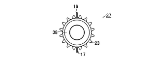
- a terminal-side sprocket 38 that contacts the inner peripheral surface of the endless conveyor 11 at the terminal position of the output region ⁇ , and a terminal-side transfer support portion 41 having a terminal-side rotating shaft 40 that connects the terminal-side sprocket 38. It is configured.
- the terminal side transfer support part 41 is provided at a position horizontally deviated toward the concentrated egg collection conveyor 7 side with respect to the vertical track ⁇ of the endless conveyor 11.
- the vertical trajectory ⁇ of the endless conveyor 11 is changed to an oblique trajectory ⁇ , and the endless conveyor 11 is bent toward the upper rotation support portion 21 at the terminal position to be changed to a reverse oblique trajectory ⁇ . ing.
- the transfer area ⁇ At the starting position of the transfer area ⁇ , one end for guiding the egg 3 transferred by a normal transfer operation to the concentrated egg collection conveyor 7 is bent into an L-shaped cross section, and further inclined slightly toward the concentrated egg collection conveyor 7 side.
- a transfer plate 43 is provided.
- the terminal-side rotating shaft 40 of the terminal-side output support portion 41 is provided with a pair of discharge plates 16 and 17 that protrude in a direction away from each other in the radial direction of the rotating shaft and whose relative angle is set to 180 °. ing.
- the discharge plates 16 and 17 are formed of a plate-like member having a plate width that substantially matches the axial length of the terminal-side rotation shaft 40.
- the terminal-side sprocket 38 is provided with 16 meshing protrusions 23 that can mesh with the meshing hole 20 of the endless conveyor 11 on the circumference of the sprocket.
- one egg placing portion 6 is installed every time eight conveyor members 18 are connected.
- the egg placement unit 6 passes through the transfer region ⁇ twice. Further, the pair of discharge plates 16 and 17 rotate in a predetermined direction (see arrow ⁇ in FIG. 5) as the terminal side sprocket 38 rotates, and pass through the transfer region ⁇ in accordance with the passage timing of the egg placing portion 6. To do.
- FIG. 7 and FIG. 8 schematically show the vicinity of the transfer area ⁇ , the normal transfer from the egg placement unit 6 was not performed, and the egg placement unit 6 was held more than necessary.
- the assistance of the transfer of the egg 3 is shown. 7 and 8 assume that time elapses from left to right in the drawing.
- the egg 3 conveyed upward along the vertical track ⁇ of the endless conveyor 11 reaches the start position of the transfer region ⁇ .
- the endless conveyor 11 is changed from the track ⁇ in the vertical direction to the track ⁇ in the oblique direction by the transfer mechanism unit 15.
- the egg mounting part 6 also inclines with the track change of the endless conveyor 11, and the other mounting bar 31 is positioned below the mounting bar 30 on the short side part 25 side. Therefore, the egg 3 placed and held between the pair of placement bars 30 and 31 is released from the placement state according to its own weight due to the inclination, and is transferred to the concentrated egg collection conveyor 7 along the transfer plate 43.
- the mounting bar 30 close to the endless conveyor 11 connected the vertex which the long side parts 26 and 27 connected. Since there is a position slightly higher than the placement bar 31, the above-mentioned transfer is performed more easily by inclining the egg placement unit 6 in the transfer region ⁇ . Therefore, most of the eggs 3 that have reached the transfer region ⁇ are transferred by the movement of the egg placing unit 6.
- the egg placement unit 6a is held more than necessary for some reason, and the egg 3a may not be transferred only by the inclination of the egg placement unit 6a.
- the egg 3a heads toward the terminal side transfer support part 41 at the terminal position of the transfer region ⁇ while being placed on the inclined egg egg mounting part 6a (see the left end diagram in FIG. 7).
- the terminal position of the turnout region ⁇ is close to the egg 3a in conjunction with the rotation of the terminal-side sprocket 38 and the terminal-side rotating shaft 40 (see the second figure from the left in FIG. 7).
- next egg-laying portion 6b on which the new egg 3b is placed has reached the start position of the transfer area ⁇ .
- a pair of discharge plates 16 and 17 are provided on the terminal-side rotating shaft 40 in the present embodiment.
- the other discharge plate 17 is located on the opposite side of the discharge plate 16 that applies a horizontal force to the previous egg 3a and assists the transfer. Therefore, when the next egg-laying portion 6b on which a new egg 3b is placed is conveyed toward the end position (left end in FIG.
- the other discharge plate 17 provided on the terminal-side rotating shaft 40 rotates in conjunction with the terminal-side sprocket 38 and the terminal-side rotating shaft 40, and comes close to the egg placing portion 6b. As a result, it comes into contact with the egg 3b placed on the egg placing part 6b, and a horizontal force is applied toward the concentrated egg collection conveyor 7 side to assist in the transfer of the egg 3b (right end view in FIG. 8). reference). As a result, each time the terminal-side sprocket 38 makes one rotation, the egg placement unit 6 passes through the transfer area ⁇ twice, and the eggs 3a and 3b are held in the egg placement units 6a and 6b more than necessary.
- the discharge plates 16 and 17 can continuously assist the transfer, and troubles such as the dropping of the eggs 3 outside the transfer area ⁇ can be avoided.
- the rotation trajectory ⁇ of the rotating discharge plates 16 and 17 is There is no interference with the track ⁇ in the oblique direction and the track ⁇ in the reverse diagonal direction of the endless conveyor 11, and each movement is not hindered.
- the pair of discharge plates 16 and 17 provided on the terminal-side rotating shaft 40 of the terminal-side turnout support portion 41 are the endless conveyor 11 and the terminal-side sprocket 38.
- the terminal side transfer support portion 41 at the terminal position of the transfer region ⁇ , it becomes possible to assist the transfer of the eggs 3 to all the egg placement units 6 that pass through the transfer region ⁇ . .
- the effects of the present invention can be enjoyed, and an increase in equipment cost can be suppressed.
- the concentrated egg collecting conveyor 7 is provided at an upper position of the multi-stage poultry cage 2 for poultry raising, and is set at an upper position by the endless conveyor 11 of the transfer transfer device 8 at an upper position.
- the present invention is not limited to this, and the egg 3 recovered from each poultry cage is transported downward along the endless conveyor 11, and the poultry cage at the lowest stage is shown.
- the egg 3 may be transferred in the transfer region ⁇ provided at a lower position.
- the pair of discharge plates 16 and 17 are installed on the terminal-side rotating shaft 40 with the relative angle of each other being 180 °.
- the present invention is not limited to this. Instead, the number of discharge plates can be changed as appropriate. In this case, it is necessary to adjust the intervals of the egg-laying units 6 installed on the endless conveyor 11 with respect to the rotation of the terminal-side rotating shaft 40, so that the timing of assisting the transfer of the eggs 3 is achieved.
Landscapes
- Life Sciences & Earth Sciences (AREA)
- Engineering & Computer Science (AREA)
- Mechanical Engineering (AREA)
- Birds (AREA)
- Environmental Sciences (AREA)
- Zoology (AREA)
- Animal Husbandry (AREA)
- Biodiversity & Conservation Biology (AREA)
- Housing For Livestock And Birds (AREA)
- Meat, Egg Or Seafood Products (AREA)
- Chain Conveyers (AREA)
Abstract
Description
Claims (2)
- 養鶏用多段家禽ケージに付設され、複数の家禽ケージから移送された鶏卵を鉛直方向に搬送し、予め設定された転出領域で前記鶏卵を集中集卵コンベアに向けて転出させる搬送転出装置を具備する集卵機であって、
前記搬送転出装置は、
前記養鶏用多段家禽ケージのケージ側面に沿った鉛直方向の軌道を少なくとも一部に有して回転駆動される無端コンベアと、
前記無端コンベアの回転を支持する回転支持部と、
前記無端コンベアに等間隔で取設され、前記鶏卵を載置し保持する複数の鶏卵載置部と、
前記転出領域の開始位置に設けられた開始側転出支持部及び前記転出領域の終端位置に設けられた終端側転出支持部を備え、前記無端コンベアの鉛直方向の前記軌道を斜め方向に変化させ前記鶏卵載置部を傾けて前記鶏卵を転出させる転出機構部と、
前記終端側転出支持部の終端側回転軸から回転軸径方向に突設され、前記終端側回転軸の回転に伴い、前記終端位置の近傍で前記鶏卵載置部に載置された未転出の前記鶏卵と接触し前記集中集卵コンベアに向けて押出すディスチャージプレートと
を具備することを特徴とする集卵機。 - 前記ディスチャージプレートは、
前記終端側回転軸を中心として等間隔に二つ以上突設されていることを特徴とする請求項1に記載の集卵機。
Priority Applications (4)
| Application Number | Priority Date | Filing Date | Title |
|---|---|---|---|
| PCT/JP2011/058706 WO2012137319A1 (ja) | 2011-04-06 | 2011-04-06 | 集卵機 |
| JP2011523225A JP5912527B2 (ja) | 2011-04-06 | 2011-04-06 | 集卵機 |
| CN201180001377.3A CN103108817B (zh) | 2011-04-06 | 2011-04-06 | 集蛋机 |
| US13/311,178 US20120255499A1 (en) | 2011-04-06 | 2011-12-05 | Egg collector |
Applications Claiming Priority (1)
| Application Number | Priority Date | Filing Date | Title |
|---|---|---|---|
| PCT/JP2011/058706 WO2012137319A1 (ja) | 2011-04-06 | 2011-04-06 | 集卵機 |
Related Child Applications (1)
| Application Number | Title | Priority Date | Filing Date |
|---|---|---|---|
| US13/311,178 Continuation US20120255499A1 (en) | 2011-04-06 | 2011-12-05 | Egg collector |
Publications (1)
| Publication Number | Publication Date |
|---|---|
| WO2012137319A1 true WO2012137319A1 (ja) | 2012-10-11 |
Family
ID=46965106
Family Applications (1)
| Application Number | Title | Priority Date | Filing Date |
|---|---|---|---|
| PCT/JP2011/058706 Ceased WO2012137319A1 (ja) | 2011-04-06 | 2011-04-06 | 集卵機 |
Country Status (4)
| Country | Link |
|---|---|
| US (1) | US20120255499A1 (ja) |
| JP (1) | JP5912527B2 (ja) |
| CN (1) | CN103108817B (ja) |
| WO (1) | WO2012137319A1 (ja) |
Cited By (1)
| Publication number | Priority date | Publication date | Assignee | Title |
|---|---|---|---|---|
| WO2022118390A1 (ja) * | 2020-12-02 | 2022-06-09 | 株式会社ハイテム | 集卵機 |
Families Citing this family (12)
| Publication number | Priority date | Publication date | Assignee | Title |
|---|---|---|---|---|
| CN103598115A (zh) * | 2013-10-23 | 2014-02-26 | 安徽长青电子机械(集团)有限公司 | 一种蛋类自动收集装置 |
| CN106458469B (zh) * | 2014-05-05 | 2019-11-26 | 未来股份公司 | 用于控制硬纸管状芯的流动的装置 |
| CN105794686B (zh) * | 2014-12-31 | 2018-12-18 | 郑经伟 | 鸭蛋的全自动洁蛋、检测及分类装置 |
| ES2660445T3 (es) * | 2015-10-26 | 2018-03-22 | Albert Handtmann Maschinenfabrik Gmbh & Co. Kg | Dispositivo y procedimiento para descargar porciones de embutido |
| CN105432508B (zh) * | 2015-12-14 | 2018-01-09 | 广州市翔顺畜牧设备有限公司 | 一种集蛋机 |
| CN105692241A (zh) * | 2016-03-28 | 2016-06-22 | 苏州市合叶精密机械有限公司 | 一种新型自动上下料仓 |
| BR102016009259A2 (pt) * | 2016-04-26 | 2017-10-31 | Gsi Brasil Indústria E Comércio De Equipamentos Agropecuarios Ltda. | Modulavel lifting conveyor |
| CN105794683B (zh) * | 2016-05-12 | 2018-08-24 | 南京工程学院 | 一种养鸡笼的自动收蛋装置 |
| CN106472352A (zh) * | 2016-12-07 | 2017-03-08 | 成都晟兴牧业机械有限公司 | 一种纵向集蛋机 |
| CN112586397B (zh) * | 2020-12-14 | 2022-05-20 | 赣州朝歌科技有限公司 | 一种用于禽蛋采集的收放机构 |
| CN117864653B (zh) * | 2024-03-12 | 2024-05-31 | 泰州市中盛机电有限公司 | 基于铰接式可进行调节的薄膜放置架 |
| CN118058209B (zh) * | 2024-03-20 | 2024-09-27 | 山东陈氏特产食品有限公司 | 一种咸鸭蛋腌制设备及腌制方法 |
Citations (7)
| Publication number | Priority date | Publication date | Assignee | Title |
|---|---|---|---|---|
| JPS62105816A (ja) * | 1985-11-05 | 1987-05-16 | Sekisui Jushi Co Ltd | 卵の移送装置 |
| JPS62134033A (ja) * | 1985-12-09 | 1987-06-17 | 株式会社 中嶋製作所 | 卵の移送装置 |
| JPH0286721A (ja) * | 1988-09-22 | 1990-03-27 | Nakajima Seisakusho:Kk | 集卵装置 |
| JPH1156158A (ja) * | 1997-08-22 | 1999-03-02 | Toyo Syst Kk | 複数の集中集卵コンベア用集卵機 |
| JP2003259754A (ja) * | 2002-03-12 | 2003-09-16 | Toyo System Co Ltd | 集中集卵コンベアのための集卵装置 |
| JP2006191849A (ja) * | 2005-01-13 | 2006-07-27 | Toyo System Co Ltd | 集卵機の卵転出機構 |
| WO2007113919A1 (ja) * | 2006-04-06 | 2007-10-11 | Hytem Co., Ltd. | 集卵機の卵転出機構 |
Family Cites Families (4)
| Publication number | Priority date | Publication date | Assignee | Title |
|---|---|---|---|---|
| US3135386A (en) * | 1960-10-10 | 1964-06-02 | Walter J Reading | Egg grading device |
| SE358132B (ja) * | 1968-04-20 | 1973-07-23 | Mojden W | |
| DE3138748A1 (de) * | 1981-09-29 | 1983-04-14 | Salmet Gmbh & Co Kg, 6921 Ittlingen | Eiertransportvorrichtung |
| CN201485028U (zh) * | 2009-06-29 | 2010-05-26 | 湖南千山制药机械股份有限公司 | 进出瓶机构及其拨块零件 |
-
2011
- 2011-04-06 CN CN201180001377.3A patent/CN103108817B/zh active Active
- 2011-04-06 WO PCT/JP2011/058706 patent/WO2012137319A1/ja not_active Ceased
- 2011-04-06 JP JP2011523225A patent/JP5912527B2/ja active Active
- 2011-12-05 US US13/311,178 patent/US20120255499A1/en not_active Abandoned
Patent Citations (8)
| Publication number | Priority date | Publication date | Assignee | Title |
|---|---|---|---|---|
| JPS62105816A (ja) * | 1985-11-05 | 1987-05-16 | Sekisui Jushi Co Ltd | 卵の移送装置 |
| JPS62134033A (ja) * | 1985-12-09 | 1987-06-17 | 株式会社 中嶋製作所 | 卵の移送装置 |
| JPH0286721A (ja) * | 1988-09-22 | 1990-03-27 | Nakajima Seisakusho:Kk | 集卵装置 |
| JPH1156158A (ja) * | 1997-08-22 | 1999-03-02 | Toyo Syst Kk | 複数の集中集卵コンベア用集卵機 |
| JP3584150B2 (ja) * | 1997-08-22 | 2004-11-04 | 東洋システム株式会社 | 複数の集中集卵コンベア用集卵機 |
| JP2003259754A (ja) * | 2002-03-12 | 2003-09-16 | Toyo System Co Ltd | 集中集卵コンベアのための集卵装置 |
| JP2006191849A (ja) * | 2005-01-13 | 2006-07-27 | Toyo System Co Ltd | 集卵機の卵転出機構 |
| WO2007113919A1 (ja) * | 2006-04-06 | 2007-10-11 | Hytem Co., Ltd. | 集卵機の卵転出機構 |
Cited By (2)
| Publication number | Priority date | Publication date | Assignee | Title |
|---|---|---|---|---|
| WO2022118390A1 (ja) * | 2020-12-02 | 2022-06-09 | 株式会社ハイテム | 集卵機 |
| JP7636009B2 (ja) | 2020-12-02 | 2025-02-26 | 株式会社ハイテム | 集卵機 |
Also Published As
| Publication number | Publication date |
|---|---|
| US20120255499A1 (en) | 2012-10-11 |
| CN103108817A (zh) | 2013-05-15 |
| CN103108817B (zh) | 2015-08-05 |
| JP5912527B2 (ja) | 2016-04-27 |
| JPWO2012137319A1 (ja) | 2014-07-28 |
Similar Documents
| Publication | Publication Date | Title |
|---|---|---|
| JP5912527B2 (ja) | 集卵機 | |
| JP5171168B2 (ja) | 農産物の清浄装置 | |
| CN101442905B (zh) | 集蛋机的蛋滚出机构 | |
| JP6258517B2 (ja) | 搬送式乾燥装置 | |
| JP3881913B2 (ja) | 集中集卵コンベアのための集卵装置 | |
| JP3443419B2 (ja) | 土除去装置および収穫機 | |
| CN215286603U (zh) | 一种禽蛋的输送装置 | |
| CN109335637A (zh) | 一种种蛋定向排列装置 | |
| CN213140161U (zh) | 一种全自动鸡蛋拾取清洗装托码放一体机 | |
| KR101270532B1 (ko) | 패널 이송용 컨베이어 | |
| CN113229337A (zh) | 一种定位传送摊虾装置 | |
| JP5380757B1 (ja) | ゴルフボール搬送装置 | |
| HK1182367A (en) | Egg collector | |
| CN212100788U (zh) | 一种禽蛋输送调头机构 | |
| JP4876157B2 (ja) | 除糞システム | |
| JP7577355B2 (ja) | 搬送式乾燥装置及び搬送式乾燥方法 | |
| JP5689030B2 (ja) | 搬送路開閉装置 | |
| JP2006191849A (ja) | 集卵機の卵転出機構 | |
| CN223804536U (zh) | 一种具有喷淋结构的露天煤矿开采用物料输送结构 | |
| CN223149612U (zh) | 一种模块化层叠传送单元装置 | |
| KR100612460B1 (ko) | 도장품 이송용 컨베이어의 듀얼 이송 장치 | |
| JP4444760B2 (ja) | 製茶合組機 | |
| CN107882937A (zh) | 一种蛋爪及蛋爪组成的传动链及传动链构成的传动装置 | |
| JP2006000021A (ja) | 農作物順次供給装置 | |
| SU1405786A1 (ru) | Устройство дл очистки и сортировки картофел |
Legal Events
| Date | Code | Title | Description |
|---|---|---|---|
| WWE | Wipo information: entry into national phase |
Ref document number: 201180001377.3 Country of ref document: CN |
|
| ENP | Entry into the national phase |
Ref document number: 2011523225 Country of ref document: JP Kind code of ref document: A |
|
| 121 | Ep: the epo has been informed by wipo that ep was designated in this application |
Ref document number: 11863159 Country of ref document: EP Kind code of ref document: A1 |
|
| NENP | Non-entry into the national phase |
Ref country code: DE |
|
| 122 | Ep: pct application non-entry in european phase |
Ref document number: 11863159 Country of ref document: EP Kind code of ref document: A1 |