WO2012137859A1 - Amplificateur hydraulique et dispositif de frein hydraulique utilisant cet amplificateur - Google Patents
Amplificateur hydraulique et dispositif de frein hydraulique utilisant cet amplificateur Download PDFInfo
- Publication number
- WO2012137859A1 WO2012137859A1 PCT/JP2012/059315 JP2012059315W WO2012137859A1 WO 2012137859 A1 WO2012137859 A1 WO 2012137859A1 JP 2012059315 W JP2012059315 W JP 2012059315W WO 2012137859 A1 WO2012137859 A1 WO 2012137859A1
- Authority
- WO
- WIPO (PCT)
- Prior art keywords
- pressure
- hydraulic
- hydraulic pressure
- boost
- booster
- Prior art date
- Legal status (The legal status is an assumption and is not a legal conclusion. Google has not performed a legal analysis and makes no representation as to the accuracy of the status listed.)
- Ceased
Links
Images


Classifications
-
- B—PERFORMING OPERATIONS; TRANSPORTING
- B60—VEHICLES IN GENERAL
- B60T—VEHICLE BRAKE CONTROL SYSTEMS OR PARTS THEREOF; BRAKE CONTROL SYSTEMS OR PARTS THEREOF, IN GENERAL; ARRANGEMENT OF BRAKING ELEMENTS ON VEHICLES IN GENERAL; PORTABLE DEVICES FOR PREVENTING UNWANTED MOVEMENT OF VEHICLES; VEHICLE MODIFICATIONS TO FACILITATE COOLING OF BRAKES
- B60T13/00—Transmitting braking action from initiating means to ultimate brake actuator with power assistance or drive; Brake systems incorporating such transmitting means, e.g. air-pressure brake systems
- B60T13/10—Transmitting braking action from initiating means to ultimate brake actuator with power assistance or drive; Brake systems incorporating such transmitting means, e.g. air-pressure brake systems with fluid assistance, drive, or release
- B60T13/12—Transmitting braking action from initiating means to ultimate brake actuator with power assistance or drive; Brake systems incorporating such transmitting means, e.g. air-pressure brake systems with fluid assistance, drive, or release the fluid being liquid
- B60T13/14—Transmitting braking action from initiating means to ultimate brake actuator with power assistance or drive; Brake systems incorporating such transmitting means, e.g. air-pressure brake systems with fluid assistance, drive, or release the fluid being liquid using accumulators or reservoirs fed by pumps
- B60T13/142—Systems with master cylinder
- B60T13/145—Master cylinder integrated or hydraulically coupled with booster
-
- B—PERFORMING OPERATIONS; TRANSPORTING
- B60—VEHICLES IN GENERAL
- B60T—VEHICLE BRAKE CONTROL SYSTEMS OR PARTS THEREOF; BRAKE CONTROL SYSTEMS OR PARTS THEREOF, IN GENERAL; ARRANGEMENT OF BRAKING ELEMENTS ON VEHICLES IN GENERAL; PORTABLE DEVICES FOR PREVENTING UNWANTED MOVEMENT OF VEHICLES; VEHICLE MODIFICATIONS TO FACILITATE COOLING OF BRAKES
- B60T8/00—Arrangements for adjusting wheel-braking force to meet varying vehicular or ground-surface conditions, e.g. limiting or varying distribution of braking force
- B60T8/32—Arrangements for adjusting wheel-braking force to meet varying vehicular or ground-surface conditions, e.g. limiting or varying distribution of braking force responsive to a speed condition, e.g. acceleration or deceleration
- B60T8/34—Arrangements for adjusting wheel-braking force to meet varying vehicular or ground-surface conditions, e.g. limiting or varying distribution of braking force responsive to a speed condition, e.g. acceleration or deceleration having a fluid pressure regulator responsive to a speed condition
- B60T8/42—Arrangements for adjusting wheel-braking force to meet varying vehicular or ground-surface conditions, e.g. limiting or varying distribution of braking force responsive to a speed condition, e.g. acceleration or deceleration having a fluid pressure regulator responsive to a speed condition having expanding chambers for controlling pressure, i.e. closed systems
- B60T8/4275—Pump-back systems
-
- B—PERFORMING OPERATIONS; TRANSPORTING
- B60—VEHICLES IN GENERAL
- B60T—VEHICLE BRAKE CONTROL SYSTEMS OR PARTS THEREOF; BRAKE CONTROL SYSTEMS OR PARTS THEREOF, IN GENERAL; ARRANGEMENT OF BRAKING ELEMENTS ON VEHICLES IN GENERAL; PORTABLE DEVICES FOR PREVENTING UNWANTED MOVEMENT OF VEHICLES; VEHICLE MODIFICATIONS TO FACILITATE COOLING OF BRAKES
- B60T13/00—Transmitting braking action from initiating means to ultimate brake actuator with power assistance or drive; Brake systems incorporating such transmitting means, e.g. air-pressure brake systems
- B60T13/10—Transmitting braking action from initiating means to ultimate brake actuator with power assistance or drive; Brake systems incorporating such transmitting means, e.g. air-pressure brake systems with fluid assistance, drive, or release
- B60T13/12—Transmitting braking action from initiating means to ultimate brake actuator with power assistance or drive; Brake systems incorporating such transmitting means, e.g. air-pressure brake systems with fluid assistance, drive, or release the fluid being liquid
- B60T13/14—Transmitting braking action from initiating means to ultimate brake actuator with power assistance or drive; Brake systems incorporating such transmitting means, e.g. air-pressure brake systems with fluid assistance, drive, or release the fluid being liquid using accumulators or reservoirs fed by pumps
- B60T13/142—Systems with master cylinder
- B60T13/145—Master cylinder integrated or hydraulically coupled with booster
- B60T13/146—Part of the system directly actuated by booster pressure
-
- B—PERFORMING OPERATIONS; TRANSPORTING
- B60—VEHICLES IN GENERAL
- B60T—VEHICLE BRAKE CONTROL SYSTEMS OR PARTS THEREOF; BRAKE CONTROL SYSTEMS OR PARTS THEREOF, IN GENERAL; ARRANGEMENT OF BRAKING ELEMENTS ON VEHICLES IN GENERAL; PORTABLE DEVICES FOR PREVENTING UNWANTED MOVEMENT OF VEHICLES; VEHICLE MODIFICATIONS TO FACILITATE COOLING OF BRAKES
- B60T13/00—Transmitting braking action from initiating means to ultimate brake actuator with power assistance or drive; Brake systems incorporating such transmitting means, e.g. air-pressure brake systems
- B60T13/10—Transmitting braking action from initiating means to ultimate brake actuator with power assistance or drive; Brake systems incorporating such transmitting means, e.g. air-pressure brake systems with fluid assistance, drive, or release
- B60T13/12—Transmitting braking action from initiating means to ultimate brake actuator with power assistance or drive; Brake systems incorporating such transmitting means, e.g. air-pressure brake systems with fluid assistance, drive, or release the fluid being liquid
- B60T13/14—Transmitting braking action from initiating means to ultimate brake actuator with power assistance or drive; Brake systems incorporating such transmitting means, e.g. air-pressure brake systems with fluid assistance, drive, or release the fluid being liquid using accumulators or reservoirs fed by pumps
- B60T13/142—Systems with master cylinder
- B60T13/147—In combination with distributor valve
-
- B—PERFORMING OPERATIONS; TRANSPORTING
- B60—VEHICLES IN GENERAL
- B60T—VEHICLE BRAKE CONTROL SYSTEMS OR PARTS THEREOF; BRAKE CONTROL SYSTEMS OR PARTS THEREOF, IN GENERAL; ARRANGEMENT OF BRAKING ELEMENTS ON VEHICLES IN GENERAL; PORTABLE DEVICES FOR PREVENTING UNWANTED MOVEMENT OF VEHICLES; VEHICLE MODIFICATIONS TO FACILITATE COOLING OF BRAKES
- B60T13/00—Transmitting braking action from initiating means to ultimate brake actuator with power assistance or drive; Brake systems incorporating such transmitting means, e.g. air-pressure brake systems
- B60T13/10—Transmitting braking action from initiating means to ultimate brake actuator with power assistance or drive; Brake systems incorporating such transmitting means, e.g. air-pressure brake systems with fluid assistance, drive, or release
- B60T13/66—Electrical control in fluid-pressure brake systems
- B60T13/662—Electrical control in fluid-pressure brake systems characterised by specified functions of the control system components
-
- B—PERFORMING OPERATIONS; TRANSPORTING
- B60—VEHICLES IN GENERAL
- B60T—VEHICLE BRAKE CONTROL SYSTEMS OR PARTS THEREOF; BRAKE CONTROL SYSTEMS OR PARTS THEREOF, IN GENERAL; ARRANGEMENT OF BRAKING ELEMENTS ON VEHICLES IN GENERAL; PORTABLE DEVICES FOR PREVENTING UNWANTED MOVEMENT OF VEHICLES; VEHICLE MODIFICATIONS TO FACILITATE COOLING OF BRAKES
- B60T13/00—Transmitting braking action from initiating means to ultimate brake actuator with power assistance or drive; Brake systems incorporating such transmitting means, e.g. air-pressure brake systems
- B60T13/10—Transmitting braking action from initiating means to ultimate brake actuator with power assistance or drive; Brake systems incorporating such transmitting means, e.g. air-pressure brake systems with fluid assistance, drive, or release
- B60T13/66—Electrical control in fluid-pressure brake systems
- B60T13/68—Electrical control in fluid-pressure brake systems by electrically-controlled valves
- B60T13/686—Electrical control in fluid-pressure brake systems by electrically-controlled valves in hydraulic systems or parts thereof
-
- B—PERFORMING OPERATIONS; TRANSPORTING
- B60—VEHICLES IN GENERAL
- B60T—VEHICLE BRAKE CONTROL SYSTEMS OR PARTS THEREOF; BRAKE CONTROL SYSTEMS OR PARTS THEREOF, IN GENERAL; ARRANGEMENT OF BRAKING ELEMENTS ON VEHICLES IN GENERAL; PORTABLE DEVICES FOR PREVENTING UNWANTED MOVEMENT OF VEHICLES; VEHICLE MODIFICATIONS TO FACILITATE COOLING OF BRAKES
- B60T7/00—Brake-action initiating means
- B60T7/02—Brake-action initiating means for personal initiation
- B60T7/04—Brake-action initiating means for personal initiation foot actuated
- B60T7/042—Brake-action initiating means for personal initiation foot actuated by electrical means, e.g. using travel or force sensors
-
- B—PERFORMING OPERATIONS; TRANSPORTING
- B60—VEHICLES IN GENERAL
- B60T—VEHICLE BRAKE CONTROL SYSTEMS OR PARTS THEREOF; BRAKE CONTROL SYSTEMS OR PARTS THEREOF, IN GENERAL; ARRANGEMENT OF BRAKING ELEMENTS ON VEHICLES IN GENERAL; PORTABLE DEVICES FOR PREVENTING UNWANTED MOVEMENT OF VEHICLES; VEHICLE MODIFICATIONS TO FACILITATE COOLING OF BRAKES
- B60T8/00—Arrangements for adjusting wheel-braking force to meet varying vehicular or ground-surface conditions, e.g. limiting or varying distribution of braking force
- B60T8/17—Using electrical or electronic regulation means to control braking
-
- B—PERFORMING OPERATIONS; TRANSPORTING
- B60—VEHICLES IN GENERAL
- B60T—VEHICLE BRAKE CONTROL SYSTEMS OR PARTS THEREOF; BRAKE CONTROL SYSTEMS OR PARTS THEREOF, IN GENERAL; ARRANGEMENT OF BRAKING ELEMENTS ON VEHICLES IN GENERAL; PORTABLE DEVICES FOR PREVENTING UNWANTED MOVEMENT OF VEHICLES; VEHICLE MODIFICATIONS TO FACILITATE COOLING OF BRAKES
- B60T8/00—Arrangements for adjusting wheel-braking force to meet varying vehicular or ground-surface conditions, e.g. limiting or varying distribution of braking force
- B60T8/32—Arrangements for adjusting wheel-braking force to meet varying vehicular or ground-surface conditions, e.g. limiting or varying distribution of braking force responsive to a speed condition, e.g. acceleration or deceleration
- B60T8/34—Arrangements for adjusting wheel-braking force to meet varying vehicular or ground-surface conditions, e.g. limiting or varying distribution of braking force responsive to a speed condition, e.g. acceleration or deceleration having a fluid pressure regulator responsive to a speed condition
- B60T8/44—Arrangements for adjusting wheel-braking force to meet varying vehicular or ground-surface conditions, e.g. limiting or varying distribution of braking force responsive to a speed condition, e.g. acceleration or deceleration having a fluid pressure regulator responsive to a speed condition co-operating with a power-assist booster means associated with a master cylinder for controlling the release and reapplication of brake pressure through an interaction with the power assist device, i.e. open systems
- B60T8/441—Arrangements for adjusting wheel-braking force to meet varying vehicular or ground-surface conditions, e.g. limiting or varying distribution of braking force responsive to a speed condition, e.g. acceleration or deceleration having a fluid pressure regulator responsive to a speed condition co-operating with a power-assist booster means associated with a master cylinder for controlling the release and reapplication of brake pressure through an interaction with the power assist device, i.e. open systems using hydraulic boosters
Definitions
- a hydraulic booster that generates an assisting force according to an operation amount of a brake operating member using a hydraulic pressure supplied from an auxiliary hydraulic pressure source and applies the assisted force to a master cylinder, and a hydraulic pressure thereof
- the present invention relates to a hydraulic brake device including a booster.
- the hydraulic pressure supplied from an auxiliary hydraulic pressure source equipped with a power-driven pump and a pressure accumulator is adjusted to a value corresponding to the operation amount of the brake operating member with a pressure adjusting device having a spool valve, and is introduced into the boost chamber.
- the hydraulic pressure is applied to the boost piston to generate an assisting force corresponding to the amount of brake operation, and the assisted force (the force obtained by adding the assisting force to the braking operation force by the vehicle driver) is applied to the piston of the master cylinder.
- Patent Document 1 As a basic technology of the hydraulic booster, there is one disclosed in Patent Document 1 below.
- a hydraulic brake device including a reflux type pressure adjusting unit that executes ABS (anti-lock control) and ESC (vehicle stabilization control) based on a command from an electronic control device is on the market.
- the recirculation type pressure adjustment unit is used to reduce the pressure of the wheel cylinder based on information from various known sensors that detect wheel speed, operation stroke of the brake operation member, brake fluid pressure, vehicle behavior, etc. Is determined, the hydraulic pressure path from the master cylinder to the wheel cylinder is shut off by the pressure increasing solenoid valve, and the pressure reducing solenoid valve connects the wheel cylinder to the low pressure reservoir to perform pressure reduction control.
- the power-driven recirculation pump is driven to pump up the brake fluid in the low-pressure liquid reservoir, the pressure increasing solenoid valve is opened, and the pressure reducing solenoid valve is opened.
- the brake fluid pumped up by closing is returned to the hydraulic pressure path from the master cylinder to the wheel cylinder.
- the hydraulic brake device adopting this reflux type pressure adjusting unit is located upstream of the position (reflux point) where the brake fluid pumped up by the pump for reflux is introduced into the hydraulic pressure path from the master cylinder to the wheel cylinder (master point).
- a shut-off valve is installed on the cylinder side) and the shut-off valve is closed when control such as ABS is executed, and a shut-off valve is not installed.
- a conventional hydraulic brake device equipped with a reflux type pressure adjustment unit which is combined with a booster that assists the driver's braking operation, employs a vacuum booster that generates the assisting force using the negative pressure of the engine.
- a vacuum booster that generates the assisting force using the negative pressure of the engine.
- valve lifted vehicles, HEVs (hybrid vehicles), EVs (electric vehicles), etc. that make the intake valve function as a throttle valve by making the lift amount of the intake valve continuously variable, assistance due to negative engine pressure cannot be expected.
- Combining hydraulic boosters is being considered.
- the hydraulic booster causes the hydraulic pressure (boost pressure) introduced into the boost chamber to act on the boost piston to generate an assisting force.
- the piston of the master cylinder (master piston) is pushed back by the hydraulic pressure flowing back from the pressure adjusting unit, and the force is transmitted to the boost piston (called power piston in the vacuum booster) to boost.
- the piston is pushed back.
- a hydraulic brake system that employs a vacuum booster that activates the power piston by the pressure difference between the negative pressure chamber and the atmospheric chamber and generates an assisting force, even if the power piston is pushed back, it is compressed by the displacement of the power piston. Since the air is confined in the atmosphere chamber, the pressure increase in the atmosphere chamber is not so large, and the influence of the pump back can be minimized.
- the brake fluid contained in the boost chamber is compressed when the boost piston is pushed back by pump back, and the brake fluid is incompressible oil. Boosting of the boost chamber until the discharge port communicating with the atmospheric pressure reservoir is opened cannot be ignored.
- the present invention provides a pump back when a hydraulic pressure booster is used in combination with a reflux type pressure adjustment unit (ABS unit or ESC unit) in order to eliminate the fear of the durability reduction or damage of the master cylinder or the hydraulic pressure booster. It is an object to suppress the abnormal increase in the master cylinder pressure and boost pressure caused.
- the present invention provides a hydraulic booster in which the following measures (1) to (3) are taken, and hydraulic brake devices (4) and (5) using the hydraulic booster. To do.
- An auxiliary hydraulic pressure source having a power-driven pump and an accumulator, and the hydraulic pressure supplied from the auxiliary hydraulic pressure source is adjusted to a value corresponding to the operation amount of the brake operating member by the displacement of the spool valve.
- a hydraulic brake comprising: a pressure adjusting device introduced into the boost chamber; and a boost piston that receives the hydraulic pressure introduced into the boost chamber to generate an assisting force and operates the master piston of the master cylinder with the assisting force.
- Liquid that bypasses the pressure regulator and connects either the boost chamber or the master cylinder pressure chamber to either the auxiliary hydraulic pressure source or the atmospheric pressure reservoir with respect to the hydraulic booster for the device A pressure path is provided, and a check valve that allows only hydraulic pressure discharge from the pressure chamber of the boost chamber or the master cylinder to the auxiliary hydraulic pressure source or the atmospheric pressure reservoir is provided in the hydraulic pressure path.
- a sticking prevention mechanism for preventing sticking of the check valve is additionally provided for the hydraulic booster taking the measure of (1).
- the anti-adhesion mechanism here refers to the check valve that opens when the brake operation is not performed by utilizing the relative movement of the two members that occurs inside the hydraulic booster due to the brake operation by the driver. The valve is moved to the valve position, and when the brake operation is started, the valve is moved back to the valve closing position.
- the boost piston, the input piston that transmits the brake operating force to the boost piston, the master piston, and the like are movable bodies and move within the booster housing when receiving the driving force. If the valve body of the check valve is supported on one of the movable body and the housing and the valve seat of the check valve is formed on the other, the check valve can be opened and closed using the relative movement of the movable body and the housing. Can do.
- a piston is provided that receives the hydraulic pressure generated in the pressure chamber of the master cylinder in response to the brake operation of the driver and the hydraulic pressure (assist pressure) introduced into the boost chamber of the hydraulic pressure booster.
- the check valve can be opened and closed by the displacement of.
- an electromagnetic actuator that is driven by detecting the start or end of the brake operation can be provided, and the check valve can be opened and closed by the driving force of the electromagnetic actuator, which can be used as a sticking prevention mechanism.
- a plurality of hydraulic pressure paths in which check valves are incorporated are provided in parallel in the hydraulic pressure booster in which the measure (1) is taken.
- the boost chamber or A relief valve is used that opens when the hydraulic pressure in the pressure chamber of the master cylinder exceeds the set value.
- a part of the hydraulic pressure path and the check valve are provided inside the boost piston or master piston.
- the check valve has a spherical valve body.
- the check valve is configured so as to open and close the hydraulic path by bringing a valve body, which is in contact with the valve seat, made of rubber or resin into and out of contact with a flat valve seat.
- the cup seal is arranged in such a direction that the cup opening of the cup seal faces the side connected to the auxiliary hydraulic pressure source of the gap, and the check valve is configured by the cup seal.
- a gap that connects the boost chamber and the auxiliary hydraulic pressure source exists in the housing that houses the boost piston, and the gap is used as the hydraulic pressure path, and the auxiliary hydraulic pressure is in the axial direction of the gap.
- annular seal member that receives the hydraulic pressure of the source and the hydraulic pressure of the boost chamber facing both surfaces, and an annular groove that accommodates the annular seal member so as to be movable in the axial direction of the boost piston,
- the annular seal member faces the annular groove of the gap with the hydraulic pressure of the auxiliary hydraulic pressure source except when the hydraulic pressure in the boost chamber exceeds a predetermined differential pressure and exceeds the hydraulic pressure of the auxiliary hydraulic pressure source.
- the annular seal member is opened at the boost chamber side only when the boost chamber side opening is held at a position to close and the boost chamber hydraulic pressure exceeds a predetermined differential pressure and exceeds the auxiliary hydraulic pressure source hydraulic pressure.
- the check chamber is configured by an annular seal member that opens the mouth so that the boost chamber communicates with the auxiliary hydraulic pressure source via the gap.
- the hydraulic booster according to v) wherein the annular seal member is accommodated in the annular groove so as to be reciprocable in the axial direction of the boost piston, and the annular seal member is disposed in the annular space of the gap.
- An O-ring that seals between the annular seal member and the groove bottom surface of the annular groove in close contact with the inner peripheral side or outer peripheral side of the annular seal member when the boost chamber side opening facing the groove is closed. Arranged inside the annular groove.
- the structures of iv), v), and vi) are configured such that the hydraulic pressure path with a check valve is provided between the boost chamber (or the pressure chamber of the master cylinder) and the auxiliary hydraulic pressure source. Applies to hydraulic brake equipment with pressure booster.
- a brake operating member for applying a brake operating force to the hydraulic booster, and a master cylinder in which a master piston is operated by the hydraulic booster
- a wheel cylinder that generates a braking force with a hydraulic pressure supplied from the master cylinder
- the pressure reducing solenoid valve for discharging the hydraulic pressure of the wheel cylinder, the pressure increasing solenoid valve for introducing the hydraulic pressure into the wheel cylinder, and the master pumping up the brake fluid discharged from the wheel cylinder via the pressure reducing solenoid valve
- a recirculation type pressure adjusting unit comprising a recirculation pump for recirculation to a hydraulic pressure path from the cylinder to the wheel cylinder;
- a hydraulic brake device that combines an electronic control device that determines whether the wheel cylinder needs to be depressurized or repressurized and issues an operation command to the pressure reducing solenoid valve and the pressure increasing solenoid valve.
- the hydraulic brake device of (4) when at least one of the master cylinder pressure and the boost pressure exceeds a preset threshold, it is detected and pumping of the brake fluid by the pump is stopped.
- a controller is provided.
- the master cylinder pressure and boost pressure mentioned here are the pressure directly detected using the pressure sensor, the electric power (current or current) supplied to the increase / decrease solenoid valve and pump drive motor included in the reflux pressure adjustment unit. Any of the pressures estimated from the voltage) may be used.
- the master cylinder pressure or boost pressure is monitored by providing a pressure sensor, when the master cylinder pressure or boost pressure increases beyond the pressure at which the check valve should operate, the cause is due to the check valve being stuck. We can guess that there is. At that time, if the pumping of the brake fluid by the pump is stopped, the abnormal increase in the master cylinder pressure and the boost pressure can be prevented.
- the hydraulic brake device When the hydraulic brake device is provided with a pressure increasing solenoid valve or a pressure reducing solenoid valve as described above, for example, as described in detail in JP-A No. 2003-19952 and JP-A No. 2007-91051 described later.
- the electronic control device By configuring the electronic control device so that the driving current and voltage supplied to the solenoid valve correspond to the differential pressure between the master cylinder pressure and the wheel cylinder pressure, the current and voltage supplied to the solenoid valve The master cylinder pressure can be estimated from the voltage.
- the motor for driving the pump of the reflux type pressure adjusting unit also has a characteristic that the driving current and voltage fluctuate depending on the load, the master cylinder pressure is estimated from the driving current and driving voltage of the motor. The pumping of the brake fluid by the pump may be stopped when the estimated master cylinder pressure increases beyond a threshold value.
- the check valve provided in the present invention is opened by the boosting of the boost chamber.
- Boost chamber pressure escapes to auxiliary fluid pressure source or atmospheric pressure reservoir. For this reason, excessive boosting of the boost chamber is suppressed, deterioration of the durability of the master cylinder and the hydraulic pressure booster due to excessive pressure is suppressed, and the fear of breakage is also eliminated.
- those provided with a plurality of hydraulic pressure paths in which the check valve is incorporated in parallel arrangement can supplement the function with a normal check valve when any of the plurality of check valves is fixed, More reliable for failsafe.
- stopping the pumping of the brake fluid based on a command from the controller is preferably implemented as an emergency response when the check valve is fixed, but it is also possible to use this function alone. Since pump back itself stops when pumping is stopped, the reduction in durability of the liquid seal part and suppression of the fear of damage to the master cylinder and hydraulic booster should be realized without a check valve. It can be used alone and is effective as a pumpback measure.
- Sectional drawing which shows the outline
- Sectional drawing which shows an example of the non-return valve employ
- Sectional drawing which shows an example of the assembly
- FIGS. 1 to 17 of the accompanying drawings an embodiment of a hydraulic booster according to the present invention and a hydraulic brake device using the hydraulic booster will be described with reference to FIGS. 1 to 17 of the accompanying drawings.
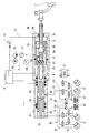
- the hydraulic brake device (first embodiment) shown in FIG. 1 is a hydraulic pressure supplied from a brake operating member (the brake pedal in the figure) 1, a master cylinder 2, a hydraulic booster 3, and a master cylinder 2.
- the wheel cylinder 4 for generating the braking force, the reflux type pressure adjusting unit 30, and the electronic control unit 5 are combined.
- Reference numeral 6 denotes an atmospheric pressure reservoir provided as a replacement fluid source. Sensors for sending information for the electronic control unit 5 to determine the necessity of pressure reduction and pressure increase of the wheel cylinder 4 are not shown in the figure.
- the master cylinder 2 is an example of a known tandem type including a return spring 2c that propels the master piston 2a to generate a hydraulic pressure in the pressure chamber 2b.
- the hydraulic booster 3 is installed between the auxiliary hydraulic pressure source 7 and the auxiliary hydraulic pressure source 7 and the boost chamber 3b, and the hydraulic pressure supplied from the auxiliary hydraulic pressure source 7 is used as the operation amount of the brake operating member 1. It has a pressure regulating device 8 that regulates the pressure to a corresponding value and introduces it into the boost chamber 3b.
- a boost piston 3c that receives a hydraulic pressure (boost pressure) introduced into the boost chamber 3b to generate an assisting force and operates the master piston 2a of the master cylinder 2 with the assisting force (thrust), and the present invention.
- a hydraulic path 12 and a check valve 13 to be characterized are included.
- the hydraulic pressure path 12 is a path that allows the boost chamber 3 b to communicate with the auxiliary hydraulic pressure source 7, and the check valve 13 is disposed in the middle of the hydraulic pressure path 12.
- the auxiliary hydraulic pressure source 7 is a combination of a pump 7a, a motor 7b for driving the pump, an accumulator 7c and a pressure sensor 7d, and the motor 7b is turned on based on a pressure detected by the pressure sensor 7d.
- the hydraulic pressure stored in the pressure accumulator 7c is kept within the specified upper and lower limit values.
- the pressure adjusting device 8 includes a spool valve 8a that is displaced by the operation force input from the brake operation member 1 and a return spring 8b of the spool valve. Moreover, it has the introduction path 8c and the discharge path 8d which were formed in the boost piston 3c.
- the introduction path 8c and the discharge path 8d are opened by the displacement of the spool valve 8a.
- the boost chamber 3b is connected to the auxiliary hydraulic pressure source 7, and when the discharge path 8d is opened, the boost chamber 3b. Is connected to the atmospheric pressure reservoir 6 via the liquid chamber 9.
- the displacement of the spool valve 8a switches the connection of the boost chamber 3b to the auxiliary hydraulic pressure source 7 and the atmospheric pressure reservoir 6 and disconnects from both the auxiliary hydraulic pressure source 7 and the atmospheric pressure reservoir 6.
- the hydraulic pressure (boost pressure) introduced from the auxiliary hydraulic pressure source 7 into the boost chamber 3b is adjusted to a value corresponding to the operation amount of the brake operating member. Since the mechanism of the pressure regulation is well-known, detailed description is omitted here.
- the boost piston 3c moves forward by receiving the boost pressure in the boost chamber 3b, and the thrust (assisted force) is transmitted to the master cylinder 2 via the power transmission member 10, and the master piston 2a is operated to enter the pressure chamber 2b. Brake fluid pressure is generated.
- the left master piston 2a is also operated by receiving the hydraulic pressure, and the left pressure chamber 2b is also operated. The same hydraulic pressure as the right side is generated.
- the pressure generated in each pressure chamber 2b of the master cylinder is a value that balances with the boost pressure in the boost chamber 3b.
- the reaction force of the pressure generated in the pressure chamber 2b is transmitted from the master piston 2a to the brake operation member 1 through the power transmission member 10, the rubber disk 11, and the spool valve 8a.
- the rubber disk 11 generates a reaction force corresponding to the brake operation amount. This is a well-known and preferred element, but it is not essential.
- the hydraulic booster can be reduced in size.
- the hydraulic pressure path 12 may be provided, and the check valve 13 may be installed in the hydraulic pressure path.
- the relay chamber 14 is provided between the boost piston 3 c and a housing (cylinder member) 3 a that accommodates the piston, and is always in communication with the auxiliary hydraulic pressure source 7.
- the check valve 13 allows passage of the hydraulic pressure flowing from the boost chamber 3b toward the auxiliary hydraulic pressure source 7, and prevents reverse flow.
- the check valve 13 used here is a combination of a valve body that receives the hydraulic pressure of the boost chamber 3b and the hydraulic pressure of the auxiliary hydraulic pressure source 7 opposite to each other, and a spring that biases the valve body in the valve closing direction. If the hydraulic pressure in the boost chamber 3b exceeds a predetermined value and exceeds the hydraulic pressure in the auxiliary hydraulic pressure source 7, the valve element is actuated by the differential pressure between the two to open.
- the recirculation type pressure adjusting unit 30 includes a pressure reducing electromagnetic valve 31 for flowing out the hydraulic pressure of the wheel cylinder 4, a pressure increasing electromagnetic valve 32 for introducing the hydraulic pressure into the wheel cylinder 4, and the wheel cylinder 4 via the pressure reducing electromagnetic valve 31.
- a low-pressure reservoir 33 for temporarily taking in the brake fluid that has flowed out from the wheel, and a recirculation pump 34 that pumps up the brake fluid that has flowed out from the wheel cylinder 4 and returns it to the hydraulic pressure path 15 from the master cylinder 2 to the wheel cylinder 4.
- the pressure reducing solenoid valve 31 and the pressure increasing solenoid valve 32 constituting the reflux type pressure adjusting unit 30 are an on / off type solenoid valve, and the opening degree of the valve portion is adjusted according to the magnitude of the current flowing through the coil. Either of the linear solenoid valves may be used.
- the hydraulic brake device of FIG. 1 configured as described above causes pump back when the pump 34 is driven by a command from the electronic control unit 5 during braking, and the master piston 2a and boost piston 3c of the master cylinder are pushed back. .
- the boost chamber 3b is separated from both the atmospheric pressure reservoir 6 and the auxiliary hydraulic pressure source 7 and sealed.
- FIG. 2 shows a hydraulic brake device according to the second embodiment.
- a hydraulic pressure path 12 is provided between the boost chamber 3 b and the atmospheric pressure reservoir 6, and a check valve 13 is disposed in the hydraulic pressure path 12.
- the check valve 13 used here is a relief valve that opens when the hydraulic pressure in the boost chamber 3b exceeds a set value.
- the hydraulic pressure path 12 and the check valve 13 are provided inside the boost piston 3c because the size can be reduced.
- the hydraulic pressure path 12 opens into the liquid chamber 9, and the boost chamber 3 b is connected to the atmospheric pressure reservoir 6 via the liquid chamber 9.
- FIGS. 5 A preferred embodiment of the check valve 13 employed in the hydraulic booster according to the present invention is shown in FIGS.
- the check valve 13 shown in FIG. 5 is configured to urge a spherical valve body 13a in a valve closing direction by a spring 13b and press it against a conical valve seat 13c, and has a simple structure and excellent productivity.
- the check valve 13 in FIG. 6 opens and closes the hydraulic pressure path 12 by bringing a valve body 13a whose contact portion with the valve seat is made of rubber or resin into and out of contact with the flat valve seat 13c.
- the check valve 13 of FIG. 6 is also simple in structure and excellent in productivity.
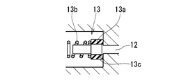
- the check valve 13 in FIG. 8 is employed in the hydraulic brake device of the first embodiment (the hydraulic brake device in FIG. 3), and has a gap 16 that communicates the boost chamber 3 b and the auxiliary hydraulic pressure source 7.
- an annular cup seal 13 d that seals the gap 16 is arranged in such a direction that the cup opening of the cup seal faces the side of the gap 16 connected to the auxiliary hydraulic pressure source 7.
- the cup seal 13d is assembled in the annular seal groove 13e.
- the gap 16 is inevitably formed inside the housing 3a for accommodating the boost piston 3c due to the structure of the hydraulic booster. As shown in FIG. 7, between a cylinder formed in the housing 3a and a boost piston 3c inserted into the cylinder, or between a guide sleeve 17 interposed between the boost piston 3c and the spool valve 8a. An inevitable gap 16 is formed, and the boost chamber 3 b and the auxiliary hydraulic pressure source 7 communicate with each other through the gap 16. For this purpose, an interface seal portion is provided in the middle of the gap 16 to seal between the boost piston 3c and the spool valve 8a.
- the seal member of the interface seal part can function as the check valve 13 of the present invention. Can do.
- the gap 16 may be newly added, but if the check valve shown in FIG. 8 is disposed in the gap inevitably generated, the seal member of the interface seal portion is simply replaced with a cup seal from an O-ring or the like. Well, no additional parts are required, and cost increases can be avoided.
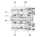
- the check valve 13 of FIG. 9 is also employed in the hydraulic brake device of the first embodiment (hydraulic brake device in FIG. 3).
- This check valve 13 is also disposed in the middle of the gap 16 by using a gap 16 that exists inside the housing 3 a and communicates the boost chamber 3 b with the auxiliary hydraulic pressure source 7.
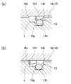
- the check valve 13 of FIG. 9 includes an annular seal member 13f having a wedge-shaped cross section that receives the hydraulic pressure of the auxiliary hydraulic pressure source 7 and the hydraulic pressure of the boost chamber 3b opposite to each other, and the annular seal member as a boost piston 3c.
- An annular groove 13g that is movably accommodated in the axial direction is provided.
- the annular seal member 13f is provided on the left end face in FIG. 9 at the position where the end face is in contact with the groove face of the annular groove 13g. There is a passage formed by a slit s communicating with.
- the annular seal member 13f is opened to the boost chamber side by the hydraulic pressure of the auxiliary hydraulic pressure source 7 except when the hydraulic pressure of the boost chamber 3b exceeds a predetermined differential pressure and exceeds the hydraulic pressure of the auxiliary hydraulic pressure source 7.
- the mouth 16i is held in a closed position.
- the boost chamber side opening 16i is opened.
- the boost chamber 3 b communicates with the auxiliary hydraulic pressure source 7 via the gap 16 so that the hydraulic pressure in the boost chamber 3 b is discharged to the auxiliary hydraulic pressure source 7.
- the annular seal member 13f of the check valve 13 in FIG. 9 is preferably made of hard resin rather than rubber. Durability is required when the hydraulic pressure difference between the boost chamber 3b and the auxiliary hydraulic pressure source 7 becomes large.
- the annular seal member 13f formed of hard resin can meet the demand.
- a taper surface corresponding to the taper surface of the annular seal member 13f is formed integrally with a member (for example, the guide sleeve 17) in which the annular groove 13g is formed.
- the annular seal member 13f may be brought into contact with the seat at the valve closing position.
- annular seal member 13f made of hard resin
- an O-ring 13h is added, and the O-ring 13h arranged in the annular groove 13g is connected to the inner periphery of the annular seal member 13f.
- the annular groove 13g is on the outer diameter side of the annular seal member 13f, it may be brought into close contact with the outer periphery of the annular seal member 13f) to create a valve-closed state.
- This structure is superior in the stability of the seal as compared with a structure in which a hard valve body and a hard valve seat are combined.
- the hydraulic pressure path 12 and the check valve 13 are provided between the boost chamber 3b and the auxiliary hydraulic pressure source 7 (or the atmospheric pressure reservoir 6).
- the pressure chamber 2b of the master cylinder and the auxiliary hydraulic pressure are provided. It may be provided between the source 7 (or the atmospheric pressure reservoir 6).
- a relief valve that opens when the master cylinder pressure exceeds the set pressure is used as the check valve 13.
- FIG. 10 shows a hydraulic pressure booster in which the check valve 13 is prevented from sticking.
- the boost chamber 3b is connected to the auxiliary hydraulic pressure source 7 through the hydraulic pressure path 12, a part of the hydraulic pressure path 12 is provided in the boost piston 3c, and the check valve 13 is provided in the boost piston 3c. Yes.
- This is the same as the hydraulic brake device of FIG. 3, and is different from the hydraulic brake device of FIG. 3 in that a sticking prevention mechanism 18 for the check valve 13 is additionally provided.
- the sticking prevention mechanism 18 provided in the hydraulic pressure booster 3 in FIG. 10 has a push pin 18a attached to the valve body 13a of the check valve 13, and a stopper 18b (in the figure, the inner end face of the housing 3a) for receiving the push pin; A valve seal 18c surrounding the opening on the boost chamber 3b side of the hydraulic pressure path 12 is provided.
- the valve body 13a and the valve seat 13c of the check valve are provided inside the boost piston 3c (the valve body 13a is prevented from coming out of the boost piston 3c), and a normal brake operation (service brake by the driver) is performed. ) And the boost piston 3c moves forward from the initial position (position where it abuts against the stopper 18b), the check valve 13 closes and the push pin 18a protrudes into the boost chamber 3b.
- the check valve 13 is opened and closed every time the driver performs a braking operation, and the check valve 13 does not operate for a long time. Sticking due to time inactivity is avoided.
- This embodiment of FIG. 10 is advantageous in terms of downsizing and space saving because the check valve 13 and the sticking prevention mechanism 18 are built in the boost piston 3b.
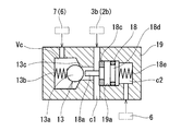
- the sticking prevention mechanism 18 may be as shown in FIGS.
- a valve chamber Vc with a valve seat 13 c is formed inside the housing 19, and the check valve 13 is formed by disposing the valve body 13 a in the valve chamber.
- a cylinder 19a is formed inside the casing 19 in which the check valve is built, and a valve seal 18c is provided on one surface of the cylinder 19 and the one surface leads to the boost chamber 3b or the pressure chamber 2b of the master cylinder.
- a piston 18d facing the liquid chamber c1 and facing the liquid chamber c2 whose other surface communicates with the atmospheric pressure reservoir 6 is assembled.
- the piston 18d is urged by the spring 18e toward the check valve 13, and the valve body 13a is pushed by the push pin 18a provided on the piston 18d when the brake is not operated when the hydraulic pressure is not introduced into the liquid chamber c1.
- the stop valve 13 is opened, and at the same time, the hydraulic pressure path 12 is blocked by the valve seal 18c.
- the sticking prevention mechanism 18 of this aspect connects the valve chamber Vc to either the auxiliary hydraulic pressure source 7 or the atmospheric pressure reservoir 6, the liquid chamber c1 to either the boost chamber 3b, or the pressure chamber 2b of the master cylinder.
- the liquid chamber c2 is connected to the atmospheric pressure reservoir 6 for use.
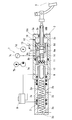
- the piston 18d is a stepped piston, and the hydraulic pressure introduced into the liquid chamber c1 and the hydraulic pressure introduced into the liquid chamber c3 are applied to one side of the piston.
- One of the liquid chamber c1 and the liquid chamber c3 is connected to the boost chamber 3b, and the other is connected to the pressure chamber 2b of the master cylinder.
- Others are configured similarly to the embodiment of FIG. This aspect also operates in the same manner as the aspect of FIG.
- the piston 18d is a stepped piston, the end face of the small diameter portion of the piston faces the liquid chamber c1, the end face of the step portion faces the liquid chamber c3, and the other end of the piston 18d faces the liquid chamber c2. ing. Further, in this aspect, a part of the hydraulic pressure path 12 is provided in the piston 18d, and the check valve 13 is disposed in that path, that is, in the piston 18d.
- the liquid chamber c1 is either the auxiliary hydraulic pressure source 7 or the atmospheric pressure reservoir 6, the liquid chamber c3 is the atmospheric pressure reservoir 6, and the liquid chamber c2 is either the boost chamber 3b or the master cylinder pressure chamber 2b. This point is different from the embodiment of FIG.
- the housing 19 shown in FIGS. 11 to 13 may be either integral with or separate from the hydraulic booster housing 3a.
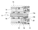
- a guide sleeve 17 for inserting the spool valve 8 a is provided inside the boost piston 3 c, and the check sleeve and a part of the hydraulic pressure path 12 connecting the boost chamber 3 b to the atmospheric pressure reservoir 6 are non-returned inside the guide sleeve.
- a valve 13 is provided, one end of the check valve spring 13b is fixed to the input piston 20 for transmitting the brake operating force to the spool valve 8a, and the valve body 13a is fixed to the other end of the spring 13b.
- valve body 13a when the brake operation by the driver is released and the input piston 20 returns to the initial position, the valve body 13a is separated from the valve seat 13c and the check valve 13 is opened.
- the driver performs a brake operation, the input piston 20 moves forward, the valve body 13a contacts the valve seat 13c, and the check valve 13 closes.
- FIG. 15 shows a hydraulic brake device according to the third embodiment (elements on the downstream side of the master cylinder 2 are not shown).
- a plurality of hydraulic pressure paths 12 in which check valves 13 are incorporated are arranged in parallel in the hydraulic pressure booster 3 for redundancy.
- any of the other check valves maintains a normal state and exhibits the initial function, so that it is possible to avoid abnormal boosting of the boost pressure or master cylinder pressure. It will be more reliable and more reliable with respect to failsafe.
- 16 and 17 show a hydraulic brake device according to the fourth embodiment.
- the hydraulic brake device of FIG. 16 is provided with a pressure sensor 21 and a controller 22 for detecting the master cylinder pressure in the hydraulic brake device of the first embodiment (the check valve sticking prevention mechanism is not shown).
- the cylinder pressure exceeds a preset threshold value, pumping of the brake fluid by the pump 34 of the reflux type pressure adjusting unit 30 is stopped by a command from the controller 22.
- the application target may be the hydraulic brake device of the second embodiment or the third embodiment.
- the threshold value in this case is set so that a pumping stop command is issued when the master cylinder pressure exceeds the pressure at which the check valve 13 normally opens.
- the boost pressure may be monitored using a pressure sensor instead of the master cylinder pressure, and when the boost pressure exceeds a preset threshold, pumping of the brake fluid by the pump 34 may be stopped by a command from the controller 22. .
- the pressure increasing electromagnetic valve 32 and the pressure reducing electromagnetic valve 31 are provided.
- the driving force supplied to the solenoid valve based on the vehicle body speed and the wheel speed is described.
- the current can be determined according to the differential pressure between the upstream and downstream with the solenoid valve as a boundary.
- the current supplied to the solenoid valve is closely related to the load of the solenoid valve (that is, the differential pressure between the upstream and downstream), so that the master cylinder pressure can be estimated from the monitored current.
- the controller 22 monitors the current and voltage supplied to the electromagnetic valves 31 and 32, or the vehicle body speed and the wheel speed, as described above. In this way, the controller 22 estimates the master cylinder pressure in real time from the monitoring data, and when the estimated pressure exceeds a preset threshold, pumping of brake fluid by the pump 34 is stopped by a command from the controller 22. May be.
- the motor 35 for driving the pump of the reflux type pressure adjusting unit 30 has a characteristic that the driving current and voltage fluctuate according to the load (that is, the discharge pressure). From this, the master cylinder pressure can be estimated. When the estimated master cylinder pressure exceeds the threshold, pumping of the brake fluid by the pump 34 may be stopped (the configuration of this device and the control flow are the same as those in FIG. 17).
- the electronic control unit 5 determines the necessity of pressure adjustment of the wheel cylinder. In such a case, the pumping stop command from the controller 22 is stopped, the pumping command is issued again, and the pump 34 is operated.
- the hydraulic brake device having the ESC execution function generally includes a pressure sensor for detecting the master cylinder pressure, the pump brake countermeasures for both the ones with and without the check valve 13 are provided. It can be realized without major structural changes that lead to an increase in physique and cost.
Landscapes
- Engineering & Computer Science (AREA)
- Transportation (AREA)
- Mechanical Engineering (AREA)
- Physics & Mathematics (AREA)
- Fluid Mechanics (AREA)
- Braking Systems And Boosters (AREA)
- Valves And Accessory Devices For Braking Systems (AREA)
Abstract
Priority Applications (3)
| Application Number | Priority Date | Filing Date | Title |
|---|---|---|---|
| DE112012000201.6T DE112012000201B4 (de) | 2011-04-05 | 2012-04-05 | Hydraulikverstärker und Hydraulikbremssystem, das diesen verwendet |
| US13/824,837 US8534773B2 (en) | 2011-04-05 | 2012-04-05 | Hydraulic booster and hydraulic brake system using the same |
| CN201280003157.9A CN103153734B (zh) | 2011-04-05 | 2012-04-05 | 液压助力器以及使用该液压助力器的液压制动装置 |
Applications Claiming Priority (4)
| Application Number | Priority Date | Filing Date | Title |
|---|---|---|---|
| JP2011-083490 | 2011-04-05 | ||
| JP2011083490 | 2011-04-05 | ||
| JP2011162087A JP5831006B2 (ja) | 2011-04-05 | 2011-07-25 | 液圧ブースタ及びそれを用いたポンプバックタイプ液圧ブレーキ装置 |
| JP2011-162087 | 2011-07-25 |
Publications (1)
| Publication Number | Publication Date |
|---|---|
| WO2012137859A1 true WO2012137859A1 (fr) | 2012-10-11 |
Family
ID=46969249
Family Applications (1)
| Application Number | Title | Priority Date | Filing Date |
|---|---|---|---|
| PCT/JP2012/059315 Ceased WO2012137859A1 (fr) | 2011-04-05 | 2012-04-05 | Amplificateur hydraulique et dispositif de frein hydraulique utilisant cet amplificateur |
Country Status (5)
| Country | Link |
|---|---|
| US (1) | US8534773B2 (fr) |
| JP (1) | JP5831006B2 (fr) |
| CN (1) | CN103153734B (fr) |
| DE (1) | DE112012000201B4 (fr) |
| WO (1) | WO2012137859A1 (fr) |
Cited By (3)
| Publication number | Priority date | Publication date | Assignee | Title |
|---|---|---|---|---|
| CN103231703A (zh) * | 2013-05-20 | 2013-08-07 | 东风汽车公司 | 一种液压式车辆制动系统 |
| WO2014054789A1 (fr) * | 2012-10-04 | 2014-04-10 | 株式会社アドヴィックス | Servocommande hydraulique pour dispositif de frein hydraulique |
| CN103847719A (zh) * | 2012-12-04 | 2014-06-11 | 罗伯特·博世有限公司 | 带有液压伺服制动器的制动系统 |
Families Citing this family (20)
| Publication number | Priority date | Publication date | Assignee | Title |
|---|---|---|---|---|
| JP2012206686A (ja) * | 2011-03-30 | 2012-10-25 | Advics Co Ltd | 液圧ブースタ及びそれを用いた液圧ブレーキ装置 |
| JP5817179B2 (ja) * | 2011-03-30 | 2015-11-18 | 株式会社アドヴィックス | 液圧ブレーキ装置 |
| CN105593084B (zh) * | 2013-07-16 | 2019-05-14 | 福特全球技术公司 | 用于使用液压制动压力增压来控制制动压力助推器的方法和制动压力助推器装置 |
| JP6296349B2 (ja) * | 2014-06-25 | 2018-03-20 | 日立オートモティブシステムズ株式会社 | ブレーキ装置 |
| JP6197808B2 (ja) | 2015-02-27 | 2017-09-20 | 株式会社アドヴィックス | 車両用制動制御装置 |
| US10099662B2 (en) * | 2015-03-11 | 2018-10-16 | Ford Global Technologies, Llc | Braking systems including compressible medium to modify brake fluid pressure |
| DE102015204877A1 (de) * | 2015-03-18 | 2016-09-22 | Robert Bosch Gmbh | Steuervorrichtung für hydraulische Komponenten eines Bremssystems eines Fahrzeugs und Verfahren zum Ausführen einer Antiblockierfunktion an mindestens einem Radbremszylinder eines Fahrzeugs |
| CN105270375B (zh) * | 2015-10-27 | 2018-02-13 | 浙江万向精工有限公司 | 线控制动及踏板力反馈系统及制动方法 |
| DE102015223048A1 (de) | 2015-11-23 | 2017-05-24 | Continental Teves Ag & Co. Ohg | Bremsgerät für eine hydraulische Kraftfahrzeugbremsanlage |
| DE102015223047A1 (de) * | 2015-11-23 | 2017-05-24 | Continental Teves Ag & Co. Ohg | Bremsgerät für eine hydraulische Kraftfahrzeugbremsanlage |
| CN106740787A (zh) * | 2017-01-09 | 2017-05-31 | 吉林大学 | 基于分时串行与同时并行控制的线控制动系统 |
| DE102017000472A1 (de) * | 2017-01-19 | 2018-07-19 | Lucas Automotive Gmbh | Hydraulische Kraftfahrzeug-Bremsanlage und Verfahren zum Betreiben und zum Prüfen derselben |
| CN107738638B (zh) * | 2017-09-18 | 2020-03-31 | 江苏大学 | 一种具有线控制动功能的复合制动系统 |
| KR102519031B1 (ko) * | 2018-02-08 | 2023-04-06 | 에이치엘만도 주식회사 | 전자식 브레이크 시스템 |
| JP2020006870A (ja) * | 2018-07-11 | 2020-01-16 | ロベルト・ボッシュ・ゲゼルシャフト・ミト・ベシュレンクテル・ハフツングRobert Bosch Gmbh | 車両用のブレーキシステムの液圧制御ユニット |
| JP2020142756A (ja) * | 2019-03-08 | 2020-09-10 | ロベルト・ボッシュ・ゲゼルシャフト・ミト・ベシュレンクテル・ハフツングRobert Bosch Gmbh | 液圧制御ユニット |
| CN110194136B (zh) * | 2019-07-03 | 2024-12-20 | 广州电通博华汽车制动系统有限公司 | 一种具有制动备份功能的液压助力器总成装置 |
| CN111016865A (zh) * | 2020-01-08 | 2020-04-17 | 重庆理工大学 | 电子控制液压式制动助力系统 |
| JP7697804B2 (ja) * | 2021-03-26 | 2025-06-24 | 株式会社Subaru | ブレーキ装置 |
| CN112937534B (zh) * | 2021-03-31 | 2022-08-09 | 重庆长安汽车股份有限公司 | 一种汽车液压制动助力控制方法 |
Citations (2)
| Publication number | Priority date | Publication date | Assignee | Title |
|---|---|---|---|---|
| JP2003137083A (ja) * | 2001-10-31 | 2003-05-14 | Sumitomo Denko Brake Systems Kk | 液圧制御弁およびそれを用いた車両制動装置 |
| JP2012066720A (ja) * | 2010-09-24 | 2012-04-05 | Advics Co Ltd | 車両用液圧制動装置 |
Family Cites Families (13)
| Publication number | Priority date | Publication date | Assignee | Title |
|---|---|---|---|---|
| DE2837884C3 (de) | 1977-09-01 | 1994-02-24 | Girling Ltd | Hydraulischer Kraftverstärker für eine Fahrzeug-Bremsanlage |
| DE4344580C2 (de) * | 1993-12-24 | 1996-03-28 | Daimler Benz Ag | Ventilanordnung für die Bremsdrucksteuerung bei einer hydraulischen Hilfskraftbremsanlage eines Straßenfahrzeuges |
| JPH11263214A (ja) * | 1998-01-13 | 1999-09-28 | Jidosha Kiki Co Ltd | ブレーキ倍力システム |
| JP3580112B2 (ja) * | 1998-01-23 | 2004-10-20 | トヨタ自動車株式会社 | 液圧制御装置 |
| JP4089062B2 (ja) * | 1999-01-28 | 2008-05-21 | アイシン精機株式会社 | ブレーキ装置 |
| JP2002264797A (ja) * | 2001-03-12 | 2002-09-18 | Toyota Motor Corp | ブレーキ装置 |
| JP2003019952A (ja) | 2001-07-06 | 2003-01-21 | Denso Corp | ブレーキ液圧制御装置 |
| JP2003081081A (ja) * | 2001-09-17 | 2003-03-19 | Aisin Seiki Co Ltd | 車両用液圧ブレーキ装置 |
| DE102005036638A1 (de) * | 2004-10-15 | 2006-04-27 | Continental Teves Ag & Co. Ohg | Bremsanlage für Kraftfahrzeuge |
| JP4630070B2 (ja) * | 2005-01-17 | 2011-02-09 | 本田技研工業株式会社 | 液圧ブレーキ装置 |
| JP4747765B2 (ja) | 2005-09-29 | 2011-08-17 | 株式会社アドヴィックス | 車両のアンチスキッド制御装置 |
| US8186772B2 (en) * | 2007-03-30 | 2012-05-29 | Nissin Kogyo Co., Ltd. | Vehicle brake apparatus |
| JP4700743B2 (ja) * | 2009-03-26 | 2011-06-15 | 日信工業株式会社 | 車両用ブレーキ装置 |
-
2011
- 2011-07-25 JP JP2011162087A patent/JP5831006B2/ja not_active Expired - Fee Related
-
2012
- 2012-04-05 US US13/824,837 patent/US8534773B2/en not_active Expired - Fee Related
- 2012-04-05 DE DE112012000201.6T patent/DE112012000201B4/de not_active Expired - Fee Related
- 2012-04-05 WO PCT/JP2012/059315 patent/WO2012137859A1/fr not_active Ceased
- 2012-04-05 CN CN201280003157.9A patent/CN103153734B/zh not_active Expired - Fee Related
Patent Citations (2)
| Publication number | Priority date | Publication date | Assignee | Title |
|---|---|---|---|---|
| JP2003137083A (ja) * | 2001-10-31 | 2003-05-14 | Sumitomo Denko Brake Systems Kk | 液圧制御弁およびそれを用いた車両制動装置 |
| JP2012066720A (ja) * | 2010-09-24 | 2012-04-05 | Advics Co Ltd | 車両用液圧制動装置 |
Cited By (3)
| Publication number | Priority date | Publication date | Assignee | Title |
|---|---|---|---|---|
| WO2014054789A1 (fr) * | 2012-10-04 | 2014-04-10 | 株式会社アドヴィックス | Servocommande hydraulique pour dispositif de frein hydraulique |
| CN103847719A (zh) * | 2012-12-04 | 2014-06-11 | 罗伯特·博世有限公司 | 带有液压伺服制动器的制动系统 |
| CN103231703A (zh) * | 2013-05-20 | 2013-08-07 | 东风汽车公司 | 一种液压式车辆制动系统 |
Also Published As
| Publication number | Publication date |
|---|---|
| JP2012224323A (ja) | 2012-11-15 |
| US8534773B2 (en) | 2013-09-17 |
| DE112012000201T5 (de) | 2013-08-01 |
| CN103153734A (zh) | 2013-06-12 |
| US20130175851A1 (en) | 2013-07-11 |
| JP5831006B2 (ja) | 2015-12-09 |
| DE112012000201B4 (de) | 2023-12-21 |
| CN103153734B (zh) | 2014-07-09 |
Similar Documents
| Publication | Publication Date | Title |
|---|---|---|
| JP5831006B2 (ja) | 液圧ブースタ及びそれを用いたポンプバックタイプ液圧ブレーキ装置 | |
| KR102841690B1 (ko) | 전자식 브레이크 시스템 | |
| JP5817179B2 (ja) | 液圧ブレーキ装置 | |
| EP1755933B1 (fr) | Systeme de freinage antipatinage a servocommande | |
| JP3496549B2 (ja) | 液圧ブレーキ装置 | |
| US7517027B2 (en) | Hydraulic brake device | |
| US9399453B2 (en) | Master cylinder device and hydraulic brake system using the same | |
| JP3216371B2 (ja) | 液圧制御機構およびそれを用いた車両用ブレーキ装置 | |
| CN107206982A (zh) | 制动装置以及制动系统 | |
| KR20180002825A (ko) | 브레이크 제어 장치 및 브레이크 시스템 | |
| JP4473751B2 (ja) | 液圧ブレーキ装置 | |
| CN117279811A (zh) | 用于液压操纵系统的两位三通阀设计 | |
| JP3637722B2 (ja) | ブレーキ装置 | |
| JP4774600B2 (ja) | 液圧制御装置及びそれを用いた車両制動装置 | |
| JPH0999832A (ja) | 液圧ブレーキ装置 | |
| US5947566A (en) | Brake booster system | |
| US8348351B2 (en) | Brake control device | |
| CN115335266A (zh) | 车辆用制动装置 | |
| US12552356B2 (en) | Vehicle braking device | |
| JP5772779B2 (ja) | 液圧ブレーキ装置用液圧ブースタ | |
| JP4612454B2 (ja) | ブレーキ制御装置 | |
| JP2010137659A (ja) | ブレーキ液圧制御装置 | |
| JP7552344B2 (ja) | 車両用制動装置 | |
| JP4512933B2 (ja) | 液圧ブレーキ装置 | |
| JP2008254464A (ja) | 車両用ブレーキ装置 |
Legal Events
| Date | Code | Title | Description |
|---|---|---|---|
| WWE | Wipo information: entry into national phase |
Ref document number: 201280003157.9 Country of ref document: CN |
|
| 121 | Ep: the epo has been informed by wipo that ep was designated in this application |
Ref document number: 12767367 Country of ref document: EP Kind code of ref document: A1 |
|
| WWE | Wipo information: entry into national phase |
Ref document number: 13824837 Country of ref document: US |
|
| WWE | Wipo information: entry into national phase |
Ref document number: 112012000201 Country of ref document: DE Ref document number: 1120120002016 Country of ref document: DE |
|
| 122 | Ep: pct application non-entry in european phase |
Ref document number: 12767367 Country of ref document: EP Kind code of ref document: A1 |