WO2012137954A1 - Connecteur optique - Google Patents
Connecteur optique Download PDFInfo
- Publication number
- WO2012137954A1 WO2012137954A1 PCT/JP2012/059595 JP2012059595W WO2012137954A1 WO 2012137954 A1 WO2012137954 A1 WO 2012137954A1 JP 2012059595 W JP2012059595 W JP 2012059595W WO 2012137954 A1 WO2012137954 A1 WO 2012137954A1
- Authority
- WO
- WIPO (PCT)
- Prior art keywords
- locking
- optical fiber
- boot
- flange portion
- fiber cable
- Prior art date
- Legal status (The legal status is an assumption and is not a legal conclusion. Google has not performed a legal analysis and makes no representation as to the accuracy of the status listed.)
- Ceased
Links
Images


Classifications
-
- G—PHYSICS
- G02—OPTICS
- G02B—OPTICAL ELEMENTS, SYSTEMS OR APPARATUS
- G02B6/00—Light guides; Structural details of arrangements comprising light guides and other optical elements, e.g. couplings
- G02B6/24—Coupling light guides
- G02B6/36—Mechanical coupling means
-
- G—PHYSICS
- G02—OPTICS
- G02B—OPTICAL ELEMENTS, SYSTEMS OR APPARATUS
- G02B6/00—Light guides; Structural details of arrangements comprising light guides and other optical elements, e.g. couplings
- G02B6/24—Coupling light guides
- G02B6/36—Mechanical coupling means
- G02B6/38—Mechanical coupling means having fibre to fibre mating means
- G02B6/3807—Dismountable connectors, i.e. comprising plugs
- G02B6/3887—Anchoring optical cables to connector housings, e.g. strain relief features
- G02B6/3888—Protection from over-extension or over-compression
-
- G—PHYSICS
- G02—OPTICS
- G02B—OPTICAL ELEMENTS, SYSTEMS OR APPARATUS
- G02B6/00—Light guides; Structural details of arrangements comprising light guides and other optical elements, e.g. couplings
- G02B6/24—Coupling light guides
- G02B6/36—Mechanical coupling means
- G02B6/38—Mechanical coupling means having fibre to fibre mating means
- G02B6/3807—Dismountable connectors, i.e. comprising plugs
- G02B6/3833—Details of mounting fibres in ferrules; Assembly methods; Manufacture
- G02B6/3855—Details of mounting fibres in ferrules; Assembly methods; Manufacture characterised by the method of anchoring or fixing the fibre within the ferrule
- G02B6/3857—Crimping, i.e. involving plastic deformation
-
- G—PHYSICS
- G02—OPTICS
- G02B—OPTICAL ELEMENTS, SYSTEMS OR APPARATUS
- G02B6/00—Light guides; Structural details of arrangements comprising light guides and other optical elements, e.g. couplings
- G02B6/24—Coupling light guides
- G02B6/36—Mechanical coupling means
- G02B6/38—Mechanical coupling means having fibre to fibre mating means
- G02B6/3807—Dismountable connectors, i.e. comprising plugs
- G02B6/3873—Connectors using guide surfaces for aligning ferrule ends, e.g. tubes, sleeves, V-grooves, rods, pins, balls
- G02B6/3874—Connectors using guide surfaces for aligning ferrule ends, e.g. tubes, sleeves, V-grooves, rods, pins, balls using tubes, sleeves to align ferrules
- G02B6/3878—Connectors using guide surfaces for aligning ferrule ends, e.g. tubes, sleeves, V-grooves, rods, pins, balls using tubes, sleeves to align ferrules comprising a plurality of ferrules, branching and break-out means
-
- G—PHYSICS
- G02—OPTICS
- G02B—OPTICAL ELEMENTS, SYSTEMS OR APPARATUS
- G02B6/00—Light guides; Structural details of arrangements comprising light guides and other optical elements, e.g. couplings
- G02B6/24—Coupling light guides
- G02B6/36—Mechanical coupling means
- G02B6/38—Mechanical coupling means having fibre to fibre mating means
- G02B6/3807—Dismountable connectors, i.e. comprising plugs
- G02B6/3887—Anchoring optical cables to connector housings, e.g. strain relief features
- G02B6/38875—Protection from bending or twisting
Definitions
- the present invention relates to an optical connector.
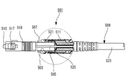
- the knob 519 is fitted with the plug frame 517, and the boot 521 is disposed so as to cover a part of the stop ring 507, the caulking ring 511, and a part of the optical fiber cable 509, and an optical fiber cable 509 with an optical connector. It was completed as.
- the present invention has been made in view of the above circumstances, and an object of the present invention is to provide an optical connector capable of preventing boot falling off due to unintentional boot pulling or loosening of an optical fiber cable without increasing the number of work steps and material costs. Is to provide.
- the locking flange portion of the boot is locked to the boot locking projection of the crimping sleeve on both sides in the diametrical direction with the center of the optical fiber cable interposed therebetween, and distortion occurs. Locks stably without deformation.
- the clamping flange portion of the crimping sleeve is locked to the boot before the boot locking projection comes into contact with the inner surface of the rear wall.
- the pressing flange portion can be pressed, and the locking flange portion can be prevented from coming off by both the clamping and locking actions.
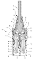
- optical connector 11 is connected to a state in which the tip of the optical fiber 15 that is the core of the optical fiber cable 13 is abutted with each other by being coupled to a not-shown counterpart optical connector.
- optical fibers in an automotive LAN or the like are connected to each other.
- the ferrule 19 that is elastically biased forward by the leaf spring 37 is further forward when the annular portion 45 abuts against a stopper wall 43 protruding from the ferrule housing hole 41. Is prevented from protruding.
- the ferrule 19 is butt-connected to the ferrule of the counterpart optical connector with the joint end face 47. Thereby, the optical fiber 15 terminated by the ferrule 19 so as to be connectable to the connector is connected to the optical line of the counterpart optical connector.
- the ferrule 19 can be slightly pushed backward in the connecting direction within the elastic deformation range of the leaf spring 37 when it is abutted with the counterpart optical connector, this prevents damage due to extreme stress concentration.
- the urging force of the leaf spring 37 acts as a butt force between the ferrules so that the desired connection loss can be obtained stably.
- a sleeve through hole 51 is formed in the rear wall 49 of the housing 17.
- the optical fiber 15 connected to the ferrule 19 is led out to the sleeve through hole 51.
- a caulking sleeve 21 is interposed between the optical fiber 15 and the sleeve through hole 51.
- the optical fiber 15 is led out from the cylindrical portion 53 of the crimping sleeve 21, while the outer periphery 35 of the cylindrical portion 53 is covered with a jacket 35.
- the outer jacket 35 placed on the cylindrical portion 53 is fixed to the cylindrical portion 53 by the crimping ring 29 being crimped from the outside.
- the optical fiber cable 13 and the crimping sleeve 21 are fixed integrally.
- the clamping flange portion 55 abuts against the rear wall 49 so that the caulking sleeve 21 is prevented from coming off.
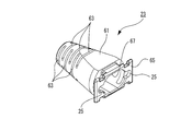
- the boot 23 is made of a soft material such as synthetic rubber, and has a protective portion 61 that covers the outer periphery of the optical fiber cable 13 and the caulking ring 29. Around the protective part 61, a plurality of circumferential grooves 63 that impart appropriate flexibility to the protective part 61 are formed.
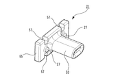
- the boot 23 has a rectangular locking flange portion 65 that passes through the sleeve through-hole 51 of the housing 17 and is connected to the protection portion 61. As shown in FIG. 2, the boot 23 is assembled to the housing 17 with the locking flange portion 65 sandwiched between the clamping flange portion 55 of the crimping sleeve 21 and the rear wall inner surface 59 of the housing 17.
- a ring receiving hole 67 for receiving the caulking ring 29 is formed at the same center.
- the ring receiving hole 67 opens at the center of the locking flange portion 65.
- a pair of protrusion locking holes 25 are formed inside the locking flange portion 65 with the ring housing hole 67 interposed therebetween. Accordingly, the pair of protrusion locking holes 25 are arranged on the left and right with the cylindrical portion 53 of the crimping sleeve 21 in between.
- the protrusion locking hole 25 is formed in a C-shape and is shared by the ring receiving hole 67 and opened to the ring receiving hole 67.
- a pair of boot locking protrusions 27 project from the clamping flange portion 55 of the crimping sleeve 21 with the clamping flange portion 55 interposed therebetween.
- the pair of boot locking projections 27 having a columnar shape are respectively fitted into the protrusion locking holes 25 of the locking flange portion 65 sandwiched between the clamping flange portion 55 and the rear wall inner surface 59.
- the protrusion length of the boot locking protrusion 27 is set to be smaller than the thickness of the locking flange portion 65.
- the operation of the optical connector 11 having the above configuration will be described.
- the boot 23, the crimping ring 29, and the crimping sleeve 21 are sequentially inserted into the optical fiber cable 13.
- the exposed optical fiber 15 is inserted inside the cylindrical portion 53 of the crimping sleeve 21 and the outer sheath 35 is removed, and the outer sheath 35 of the optical fiber cable 13 is inserted into the outer periphery of the cylindrical portion 53 by the crimping ring 29. Fixed.
- the caulking sleeve 21 fixed to the optical fiber cable 13 is restricted from being pulled out by the clamping flange portion 55 facing the rear wall inner surface 59 inside the housing 17.
- the locking flange portion 65 connected to the protective portion 61 through the sleeve through hole 51 is provided on the boot sleeve 21. It is sandwiched between the clamping flange portion 55 and the rear wall inner surface 59 of the housing 17. Further, the boot locking projection 27 protruding from the clamping flange portion 55 is inserted into the projection locking hole 25 formed in the locking flange portion 65.
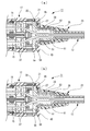
- the optical connector 11 assembled in this manner is a locking flange that is sandwiched between the clamping flange portion 55 and the rear wall inner surface 59 when the boot 23 is pulled alone.
- the portion 65 is pulled toward the sleeve through hole 51.
- the protrusion locking hole 25 that moves radially inward is locked to the boot locking protrusion 27. Omission is prevented.
- the caulking ring 29 is used as shown in FIG.
- the clamping flange portion 55 of the fixed caulking sleeve 21 is pressed against the rear wall inner surface 59.
- the clamping flange portion 55 pressed against the rear wall inner surface 59 clamps the locking flange portion 65 of the boot 23 with the rear wall inner surface 59, and the boot locking projection 27 is pressed against the rear wall inner surface 59. Therefore, the locking flange portion 65 can be more reliably prevented from coming off.
- optical connector 11 of the present embodiment it is possible to prevent the boot from falling off due to unintentional boot pulling or loosening of the optical fiber cable without increasing the work man-hours and material costs.
- the protrusion locking hole 25 formed inside the locking flange portion 65 has been described as a configuration example opened in a C shape.
- the optical connector according to the present invention is It is not limited to.
- the boot 73 shown in FIG. 6 it may be configured by a protrusion locking hole 69 in which the periphery of the hole is closed, and the opening shape is not limited to a circle, and various shapes such as an ellipse and a polygon can be adopted.
- the boot locking projections of the clamping flange portion inserted into the projection locking holes of the locking flange portion can take various shapes such as an elliptical column shape and a polygonal column shape as well as a cylindrical shape.
- optical connector of the present invention it is possible to prevent the boot from falling off due to unintentional boot pulling or loosening of the optical fiber cable without increasing work man-hours and material costs.
Landscapes
- Physics & Mathematics (AREA)
- General Physics & Mathematics (AREA)
- Optics & Photonics (AREA)
- Mechanical Coupling Of Light Guides (AREA)
Abstract
La présente invention porte sur un connecteur optique (11), lequel connecteur comporte un manchon de sertissage (21) ayant une partie de bride de prise en sandwich (55) opposée à une surface interne de paroi arrière (59), qui est reliée consécutivement à une partie de tube (53) à travers laquelle est insérée une fibre optique (15), la partie de tube étant insérée à travers un trou traversant de manchon (51) qui est formé à une paroi arrière (49) d'un boîtier (17), à une bague de compression (29), et à une gaine (23) ayant une bride de verrouillage (65) qui est reliée consécutivement à une partie de protection (61) pour recouvrir la périphérie externe d'un câble à fibre optique (13) et à la bague de compression (29). Une saillie de verrouillage de gaine (27) formée au niveau de la partie de bride de prise en sandwich (55) est insérée dans un trou de verrouillage de saillie (25) formé dans la bride de verrouillage (65).
Priority Applications (4)
| Application Number | Priority Date | Filing Date | Title |
|---|---|---|---|
| KR1020137026639A KR101462365B1 (ko) | 2011-04-08 | 2012-04-06 | 광 커넥터 |
| EP12767593.2A EP2696228A4 (fr) | 2011-04-08 | 2012-04-06 | Connecteur optique |
| CN2012800174214A CN103460096A (zh) | 2011-04-08 | 2012-04-06 | 光纤连接器 |
| US14/048,260 US20140037252A1 (en) | 2011-04-08 | 2013-10-08 | Optical connector |
Applications Claiming Priority (2)
| Application Number | Priority Date | Filing Date | Title |
|---|---|---|---|
| JP2011-086529 | 2011-04-08 | ||
| JP2011086529A JP2012220731A (ja) | 2011-04-08 | 2011-04-08 | 光コネクタ |
Related Child Applications (1)
| Application Number | Title | Priority Date | Filing Date |
|---|---|---|---|
| US14/048,260 Continuation US20140037252A1 (en) | 2011-04-08 | 2013-10-08 | Optical connector |
Publications (1)
| Publication Number | Publication Date |
|---|---|
| WO2012137954A1 true WO2012137954A1 (fr) | 2012-10-11 |
Family
ID=46969342
Family Applications (1)
| Application Number | Title | Priority Date | Filing Date |
|---|---|---|---|
| PCT/JP2012/059595 Ceased WO2012137954A1 (fr) | 2011-04-08 | 2012-04-06 | Connecteur optique |
Country Status (6)
| Country | Link |
|---|---|
| US (1) | US20140037252A1 (fr) |
| EP (1) | EP2696228A4 (fr) |
| JP (1) | JP2012220731A (fr) |
| KR (1) | KR101462365B1 (fr) |
| CN (1) | CN103460096A (fr) |
| WO (1) | WO2012137954A1 (fr) |
Families Citing this family (8)
| Publication number | Priority date | Publication date | Assignee | Title |
|---|---|---|---|---|
| JP6122291B2 (ja) * | 2012-08-10 | 2017-04-26 | 矢崎総業株式会社 | 光コネクタ及び光コネクタの組立方法 |
| JP6272649B2 (ja) * | 2013-02-15 | 2018-01-31 | 矢崎総業株式会社 | 光コネクタ |
| JP5736490B1 (ja) * | 2014-05-29 | 2015-06-17 | 株式会社フジクラ | コネクタ付き光ファイバユニット、光コネクタ用ブーツ |
| CN105100082A (zh) * | 2015-07-02 | 2015-11-25 | 惠州Tcl移动通信有限公司 | 云终端接入家庭云系统的方法、系统及云接入控制设备 |
| CN106918869B (zh) * | 2017-04-17 | 2018-10-26 | 深圳市飞博康光通讯技术有限公司 | 一种lc双联连接器 |
| JP6796622B2 (ja) * | 2018-07-19 | 2020-12-09 | 株式会社フジクラ | 光コネクタ |
| WO2021119369A1 (fr) * | 2019-12-10 | 2021-06-17 | Ppc Broadband, Inc. | Connecteur mécanique avec caractéristique de retenue de câble |
| JP2022050763A (ja) * | 2020-09-18 | 2022-03-31 | 矢崎総業株式会社 | 光コネクタ |
Citations (6)
| Publication number | Priority date | Publication date | Assignee | Title |
|---|---|---|---|---|
| JPH01502365A (ja) * | 1987-02-03 | 1989-08-17 | アメリカン テレフォン アンド テレグラフ カムパニー | 複式光ファイバコネクタ |
| JPH0497108A (ja) * | 1990-08-09 | 1992-03-30 | Furukawa Electric Co Ltd:The | 光コネクタ |
| JPH0520011U (ja) * | 1991-08-27 | 1993-03-12 | 日本エー・エム・ピー株式会社 | 光コネクタ |
| JPH07218764A (ja) * | 1994-01-19 | 1995-08-18 | At & T Corp | 光ファイバーコネクタ |
| JP2002533745A (ja) * | 1998-12-22 | 2002-10-08 | ラコ・エレクトロニック・データ・テクノロジー・ゲゼルシャフト・ミット・ベシュレンクテル・ハフツング | プラグハウジングを有する、光導波路用プラグ |
| JP2010266830A (ja) | 2008-06-12 | 2010-11-25 | Seikoh Giken Co Ltd | 光コネクタ用ストップリング及びそれを用いた光コネクタ付き光ファイバコード並びに光コネクタ付き光ファイバコードの製造方法。 |
Family Cites Families (8)
| Publication number | Priority date | Publication date | Assignee | Title |
|---|---|---|---|---|
| JPH077139B2 (ja) * | 1985-12-24 | 1995-01-30 | 日本電信電話株式会社 | 浮動ホルダ型光コネクタ |
| JP3282974B2 (ja) * | 1996-10-02 | 2002-05-20 | 住友電装株式会社 | 光コネクタ |
| US6422764B1 (en) * | 2000-03-01 | 2002-07-23 | Panduit Corp. | Clamping mechanism for an optical fiber |
| US7993063B2 (en) * | 2009-03-16 | 2011-08-09 | Panduit Corp. | Block-out device for fiber optic adapter |
| JP5599237B2 (ja) * | 2010-06-23 | 2014-10-01 | 矢崎総業株式会社 | 光コネクタ |
| JP5771075B2 (ja) * | 2010-12-28 | 2015-08-26 | 矢崎総業株式会社 | 光コネクタ |
| JP5882765B2 (ja) * | 2012-02-02 | 2016-03-09 | 矢崎総業株式会社 | 光コネクタ |
| JP6122291B2 (ja) * | 2012-08-10 | 2017-04-26 | 矢崎総業株式会社 | 光コネクタ及び光コネクタの組立方法 |
-
2011
- 2011-04-08 JP JP2011086529A patent/JP2012220731A/ja not_active Withdrawn
-
2012
- 2012-04-06 CN CN2012800174214A patent/CN103460096A/zh active Pending
- 2012-04-06 KR KR1020137026639A patent/KR101462365B1/ko active Active
- 2012-04-06 EP EP12767593.2A patent/EP2696228A4/fr not_active Withdrawn
- 2012-04-06 WO PCT/JP2012/059595 patent/WO2012137954A1/fr not_active Ceased
-
2013
- 2013-10-08 US US14/048,260 patent/US20140037252A1/en not_active Abandoned
Patent Citations (6)
| Publication number | Priority date | Publication date | Assignee | Title |
|---|---|---|---|---|
| JPH01502365A (ja) * | 1987-02-03 | 1989-08-17 | アメリカン テレフォン アンド テレグラフ カムパニー | 複式光ファイバコネクタ |
| JPH0497108A (ja) * | 1990-08-09 | 1992-03-30 | Furukawa Electric Co Ltd:The | 光コネクタ |
| JPH0520011U (ja) * | 1991-08-27 | 1993-03-12 | 日本エー・エム・ピー株式会社 | 光コネクタ |
| JPH07218764A (ja) * | 1994-01-19 | 1995-08-18 | At & T Corp | 光ファイバーコネクタ |
| JP2002533745A (ja) * | 1998-12-22 | 2002-10-08 | ラコ・エレクトロニック・データ・テクノロジー・ゲゼルシャフト・ミット・ベシュレンクテル・ハフツング | プラグハウジングを有する、光導波路用プラグ |
| JP2010266830A (ja) | 2008-06-12 | 2010-11-25 | Seikoh Giken Co Ltd | 光コネクタ用ストップリング及びそれを用いた光コネクタ付き光ファイバコード並びに光コネクタ付き光ファイバコードの製造方法。 |
Non-Patent Citations (1)
| Title |
|---|
| See also references of EP2696228A4 |
Also Published As
| Publication number | Publication date |
|---|---|
| EP2696228A4 (fr) | 2014-10-08 |
| EP2696228A1 (fr) | 2014-02-12 |
| KR20130136527A (ko) | 2013-12-12 |
| JP2012220731A (ja) | 2012-11-12 |
| CN103460096A (zh) | 2013-12-18 |
| US20140037252A1 (en) | 2014-02-06 |
| KR101462365B1 (ko) | 2014-11-14 |
Similar Documents
| Publication | Publication Date | Title |
|---|---|---|
| WO2012137954A1 (fr) | Connecteur optique | |
| JP6122291B2 (ja) | 光コネクタ及び光コネクタの組立方法 | |
| US9846284B2 (en) | Optical fiber connector assembly | |
| JP5882765B2 (ja) | 光コネクタ | |
| WO2014098216A1 (fr) | Connecteur optique | |
| JP2014157253A (ja) | 光コネクタ | |
| JP5873760B2 (ja) | 光コネクタ | |
| JP5695774B1 (ja) | 光コネクタおよび保護チューブの引き留め方法 | |
| JP2018081144A (ja) | 光コネクタ | |
| JP6419138B2 (ja) | コネクタ付光ファイバコード | |
| JP5145416B2 (ja) | 光コネクタおよび光コネクタの組立方法 | |
| KR101051119B1 (ko) | 현장조립형 광커넥터 | |
| JP5276905B2 (ja) | コネクタ付き光ファイバおよび光コネクタの組立方法 | |
| JP2011095493A (ja) | 光コネクタ | |
| JP2014044328A (ja) | 光コネクタ | |
| JP2014044329A (ja) | 光コネクタのケーブル保持構造 | |
| JP2010039109A (ja) | 光コネクタおよびその組立方法 | |
| JP2007256429A (ja) | 光コネクタの光ファイバ芯線保持構造 | |
| KR20120050355A (ko) | 현장조립형 광커넥터 | |
| JP2007192871A (ja) | 光コネクタ | |
| JP2001264578A (ja) | プリアセンブルプラグ及びその製造方法並びに光コネクタプラグ |
Legal Events
| Date | Code | Title | Description |
|---|---|---|---|
| 121 | Ep: the epo has been informed by wipo that ep was designated in this application |
Ref document number: 12767593 Country of ref document: EP Kind code of ref document: A1 |
|
| ENP | Entry into the national phase |
Ref document number: 20137026639 Country of ref document: KR Kind code of ref document: A |
|
| NENP | Non-entry into the national phase |
Ref country code: DE |
|
| WWE | Wipo information: entry into national phase |
Ref document number: 2012767593 Country of ref document: EP |