WO2012140856A1 - Procédé de conversion thermoélectrique et élément de conversion thermoélectrique dans lequel est utilisée la réaction d'oxydoréduction - Google Patents
Procédé de conversion thermoélectrique et élément de conversion thermoélectrique dans lequel est utilisée la réaction d'oxydoréduction Download PDFInfo
- Publication number
- WO2012140856A1 WO2012140856A1 PCT/JP2012/002391 JP2012002391W WO2012140856A1 WO 2012140856 A1 WO2012140856 A1 WO 2012140856A1 JP 2012002391 W JP2012002391 W JP 2012002391W WO 2012140856 A1 WO2012140856 A1 WO 2012140856A1
- Authority
- WO
- WIPO (PCT)
- Prior art keywords
- electrode
- thermoelectric conversion
- oxidation
- reduction reaction
- electrolyte
- Prior art date
- Legal status (The legal status is an assumption and is not a legal conclusion. Google has not performed a legal analysis and makes no representation as to the accuracy of the status listed.)
- Ceased
Links
Images




Classifications
-
- H—ELECTRICITY
- H01—ELECTRIC ELEMENTS
- H01M—PROCESSES OR MEANS, e.g. BATTERIES, FOR THE DIRECT CONVERSION OF CHEMICAL ENERGY INTO ELECTRICAL ENERGY
- H01M14/00—Electrochemical current or voltage generators not provided for in groups H01M6/00 - H01M12/00; Manufacture thereof
Definitions
- the present invention relates to a thermoelectric conversion method and a thermoelectric conversion element that convert thermal energy into electric energy, and more particularly to a thermoelectric conversion method and a thermoelectric conversion element that utilize an oxidation-reduction reaction.
- thermoelectric conversion technology is a technology that converts heat energy and electrical energy, converting waste heat generated in various daily life and production activities into electric power, or applying voltage to generate a temperature difference. It is possible to make it.
- thermoelectric conversion technique the techniques described in Patent Documents 1 to 3 below are conventionally known.
- Patent Document 1 Japanese Patent Laid-Open No. 5-144443
- a graphite sheet is placed in an aqueous solution of potassium ferrocyanide (K 4 Fe II (CN) 6 ) and potassium ferricyanide (K 3 Fe III (CN) 6 ) and boiled.
- Patent Document 2 Japanese Patent Application Laid-Open No. 5-166554
- a pair of platinum (Pt) electrodes is immersed in an aqueous solution of potassium ferrocyanide and potassium ferricyanide so that the temperature of the platinum electrode becomes 10 ° C. and 70 ° C.
- a technique for generating a thermoelectromotive force by performing is described.
- a pair of platinum electrodes is partitioned by a glass filter or an ion exchange resin diaphragm, and after the temperature difference disappears, it functions as a concentration difference battery that generates an electromotive force based on the concentration difference. Combination with is also described.
- Patent Document 3 Japanese Patent Laid-Open No. 6-140082 discloses that a temperature difference is generated in a state where a pair of electrodes (1, 3) made of the same material is immersed in a volume of ferrocyan ions and ferricyan ions. A temperature difference battery for generating a thermoelectromotive force is described. Further, in Patent Document 3, a pair of electrodes (1, 3) is partitioned by an ion exchange membrane (6), and a pair of platinum electrodes (7, 8) are arranged with the ion exchange membrane (6) sandwiched between them. It is also described that the electromotive force due to the difference is combined with a technology capable of generating.
- JP-A-5-166554 (“0011", FIG. 1) JP-A-6-140082 (“0002” to “0003”, “0019” to “0020” FIGS. 1 and 2)
- the technical problem of the present invention is to provide a thermoelectric conversion technology that is small, low-cost, and highly efficient.
- thermoelectric conversion method using the oxidation-reduction reaction of the invention according to claim 1 is: A first electrode containing an active material that transfers electrons to an electrolyte containing an alkali metal ion and a second electrode containing the same active material as the first electrode are brought into contact with each other. By heating or cooling at least one of the first electrode and the second electrode, a temperature difference is generated between the first electrode and the second electrode, so that an oxidation-reduction reaction and an electrolyte in each electrode are generated. A thermoelectromotive force is generated by the movement of alkali metal ions.
- Invention of Claim 2 is the thermoelectric conversion method using the oxidation-reduction reaction of Claim 1,
- the first electrode and the second electrode prepared by forming a film of a cyano-bridged metal complex as the active material on the surface of a conductive substrate are used.
- Invention of Claim 3 is the thermoelectric conversion method using the oxidation-reduction reaction of Claim 2,
- the first electrode and the second electrode are formed by forming a cyano-bridged metal complex on an indium tin oxide substrate surface.
- Invention of Claim 5 is the thermoelectric conversion method using the oxidation-reduction reaction of Claim 4, The first electrode and the second electrode which cause lithium deficiency are used.
- Invention of Claim 6 is the thermoelectric conversion method using the oxidation-reduction reaction of Claim 1, The first electrode and the second electrode made of carbon as the active material are used.
- Invention of Claim 7 is the thermoelectric conversion method using the oxidation-reduction reaction of Claim 6, The first electrode and the second electrode into which lithium is introduced are used.
- the invention according to claim 8 is a thermoelectric conversion method using the oxidation-reduction reaction according to claim 1, Either one of the first electrode and the second electrode is heated by solar heat.
- the invention according to claim 9 is the thermoelectric conversion method using the oxidation-reduction reaction according to claim 1,
- the layered structure including the first electrode, the second electrode, and the electrolyte is laminated so that the first electrode having one layered structure and the second electrode having the other layered structure are adjacent to each other. A temperature difference is generated between the laminated outermost first electrode and the outermost second electrode.
- the invention according to claim 10 is a thermoelectric conversion method using the oxidation-reduction reaction according to claim 1, A plurality of configurations including the first electrode, the second electrode, and the electrolyte are provided, and one of the first electrodes is connected in series to the other second electrode.
- thermoelectric conversion element using the oxidation-reduction reaction of the invention according to claim 11 is provided.
- a heated and cooled part that is provided on at least one of the first electrode and the second electrode and is heated or cooled;
- the invention according to claim 12 is the thermoelectric conversion element using the oxidation-reduction reaction according to claim 11,
- the first electrode and the second electrode prepared by forming a film of a cyano bridged metal complex as the active material on the surface of a conductive substrate, It is provided with.
- the invention according to claim 13 is the thermoelectric conversion element using the oxidation-reduction reaction according to claim 12,
- the first electrode and the second electrode having the substrate made of indium tin oxide; It is provided with.
- the invention according to claim 14 is the thermoelectric conversion element using the oxidation-reduction reaction according to claim 11,
- the first electrode and the second electrode composed of lithium cobalt oxide as the active material; It is provided with.
- the invention according to claim 15 is the thermoelectric conversion element using the oxidation-reduction reaction according to claim 14, The first electrode and the second electrode causing a lithium deficiency; It is provided with.
- the invention according to claim 16 is the thermoelectric conversion element using the oxidation-reduction reaction according to claim 11,
- the first electrode and the second electrode composed of carbon as the active material; It is provided with.
- the invention according to claim 17 is the thermoelectric conversion element using the oxidation-reduction reaction according to claim 16, The first electrode and the second electrode into which lithium is introduced; It is provided with.
- the invention according to claim 18 is the thermoelectric conversion element using the oxidation-reduction reaction according to claim 11, The heated and cooled part heated by solar heat, It is provided with.
- the invention according to claim 19 is the thermoelectric conversion element using the oxidation-reduction reaction according to claim 11,
- the layered structure including the first electrode, the second electrode, and the electrolyte is laminated so that the first electrode having one layered structure and the second electrode having the other layered structure are adjacent to each other.
- the heated / cooled portion is provided on at least one of the laminated outermost first electrode and outermost second electrode.
- the invention according to claim 20 is the thermoelectric conversion element using the oxidation-reduction reaction according to claim 11, A plurality of configurations including the first electrode, the second electrode, and the electrolyte; One of the first electrodes is connected in series to the other second electrode.
- thermoelectric conversion technique since a pair of electrode containing the same active material is made to contact the electrolyte containing an alkali metal ion, a small, low-cost, and highly efficient thermoelectric conversion technique is provided. be able to.
- the cyano bridged metal complex since the cyano bridged metal complex is used as the active material, cost reduction and thinning can be easily performed.
- the cost can be reduced as compared with the case where the ITO substrate is not used.
- the electrode comprised by lithium cobaltate since the electrode comprised by lithium cobaltate is used, the facility and material which produce the existing lithium ion battery can be utilized, and cost reduction is carried out. Is possible. According to invention of Claim 5, 15, efficiency can be improved compared with the case where lithium defect
- the efficiency can be increased as compared with the case where lithium is not introduced.
- the efficiency can be increased as compared with the case where lithium is not introduced.
- the invention described in claims 8 and 18 since solar heat is used, a clean configuration can be obtained as compared with the case where fossil fuel, nuclear power, or the like is used.
- a thermal resistance can be enlarged and thermoelectric conversion efficiency can be improved.
- FIG. 1 is an explanatory diagram of a thermoelectric conversion element according to a first embodiment of the present invention.
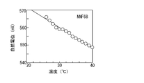
- FIG. 2 is an explanatory diagram of the experimental results of Experimental Example 1-1, in which the horizontal axis represents temperature and the vertical axis represents natural potential.
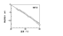
- FIG. 3 is an explanatory diagram of the experimental results of Experimental Example 1-2, in which the horizontal axis represents temperature and the vertical axis represents thermoelectromotive force.
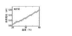
- FIG. 4 is an explanatory diagram of the experimental results of Experimental Example 2-1, in which the horizontal axis represents temperature and the vertical axis represents natural potential.
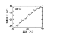
- FIG. 5 is an explanatory diagram of the experimental results of Experimental Example 2-2, in which the horizontal axis represents temperature and the vertical axis represents thermoelectromotive force.
- FIG. 1 is an explanatory diagram of a thermoelectric conversion element according to a first embodiment of the present invention.
- FIG. 2 is an explanatory diagram of the experimental results of Experimental Example 1-1, in which the horizontal axis
- FIG. 6 is an explanatory diagram of the experimental results of Experimental Example 3-1, in which the horizontal axis represents temperature and the vertical axis represents natural potential.
- FIG. 7 is an explanatory diagram of the experimental results of Experimental Example 3-2, in which the horizontal axis represents temperature and the vertical axis represents thermoelectromotive force.
- FIG. 8 is an explanatory diagram of the thermoelectric conversion element of the second embodiment, and corresponds to FIG. 1 of the first embodiment.
- FIG. 9 is an explanatory diagram of the thermoelectric conversion element according to the third embodiment of the present invention, and corresponds to FIG. 1 according to the first embodiment.
- FIG. 10 is an explanatory diagram of a thermoelectric conversion element according to the fourth embodiment of the present invention, and corresponds to FIG. FIG.
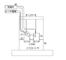
- FIG. 11 is an explanatory diagram of the measurement apparatus of Experimental Example 4.
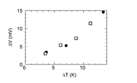
- FIG. 12 is an explanatory diagram of the experimental results of Experimental Example 4, and is a graph with the temperature difference on the horizontal axis and the potential difference on the vertical axis.
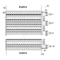
- FIG. 13 is an explanatory diagram of the thermoelectric conversion element according to the fifth embodiment of the present invention, and corresponds to FIG.
- FIG. 14 is an explanatory diagram of a module in which the thermoelectric conversion elements of Example 5 are connected in series.
- FIG. 15 is an explanatory diagram of the experimental results of Experimental Example 6, in which the horizontal axis indicates the temperature difference and the vertical axis indicates the potential difference.
- FIG. 1 is an explanatory diagram of a thermoelectric conversion element according to a first embodiment of the present invention.
- a battery 1 as an example of a thermoelectric conversion element of Example 1 of the present invention has an electrolyte tank 3 in which a liquid electrolyte 2 is accommodated.
- the electrolyte tank 3 of Example 1 has the 1st tank 3a as an example of a to-be-cooled part, the 2nd tank 3b, and the connection part 3c which connects the 1st tank 3a and the 2nd tank 3b.
- a sodium chloride (NaCl) aqueous solution containing sodium ions (Na + ) as an example of alkali metal ions is accommodated as the electrolyte 2.
- the electrolyte tank 3 as an example of the first electrode, the negative electrode 6 immersed in the first tank 3a and in contact with the electrolyte 2, and as an example of the second electrode, immersed in the second tank 3b, the electrolyte 2 is immersed. And a positive electrode 7 in contact with each other.
- the electrodes 6 and 7 of Example 1 have the same configuration, and surface layers 6b and 7b made of a cyano bridged metal complex are supported on the surfaces of the substrates 6a and 7a.
- Example 1 although the said board
- ITO Indium * Tin * Oxide, indium tin oxide
- Na 0.21 Ni [Fe (CN) 6 ] 0.68 ⁇ 5.1H 2 O as an example of a cyano bridged metal complex is used for the surface layers 6b and 7b.
- the cyano bridged metal complex is formed on the surfaces of the ITO substrates 6a and 7a by electrolytic deposition.
- the cyano bridged metal complex is not limited to this, and various conventionally known production methods such as spin coating can be employed.
- Na 0.21 Ni [Fe (CN) 6 ] 0.68 ⁇ 5.1H 2 O is taken as “N” for Na, “N” for Ni, “F” for Fe, and “68” for 0.68. , “NNF68”, and the cyano bridged metal complex is expressed in the same notation.
- a heat source 8 as an example of a heating body is installed in the first tank 3a of Example 1, and the electrolyte 2 and the positive electrode 6 accommodated in the first tank 3a are configured to be heatable.
- Example 1 In the battery 1 of Example 1 having the above-described configuration, a temperature difference does not occur between the electrolyte 2 in the first tank 3a and the electrolyte 2 in the second tank 3b when not heated by the heat source 8. No temperature difference occurs between the electrodes 6 and 7. At this time, in each of the electrodes 6 and 7, in the surface layers 6b and 7b, the oxidation reaction of the following formula (1) and the reduction reaction of the formula (2) have the same reaction rate (equilibrium), and current flows. Absent. [Fe 2+ (CN) 6] 4- ⁇ [Fe 3+ (CN) 6] 3+ e - ...
- the cyano bridged metal complex becomes an active material to transfer electrons, and a current flows between the electrodes 6 and 7. That is, in the battery 1 of Example 1, a thermoelectromotive force is generated due to the oxidation-reduction reaction between the electrolyte 2 and the electrodes 6 and 7.
- the battery 1 of Example 1 sodium ions having a small atomic weight are used as compared with the case where ferrocyan ions having a large molecular weight are used as the electrolyte as in the techniques described in the cited documents 1 to 3, and the electrolyte 2 can be expected to move ions at high speed. Therefore, it can be expected that the generation speed and responsiveness of the thermoelectromotive force are improved. Further, in the surface layers 6b and 7b of the electrodes 6 and 7 of Example 1, a cyano bridged metal complex that is easy to be thinned to a thickness of about 1 ⁇ m by electrolytic deposition or the like is used. Compared with the bulky electrodes of ⁇ 3, the size can be reduced.
- the oxidation-reduction reaction occurs uniformly at a high speed to the inside of the thin film, and there are few unused portions compared to the case of using a bulk electrode, and the electrodes 6 and 7 are used efficiently.
- the electrodes 6 and 7 of Example 1 as the substrates 6a and 7a, ITO electrodes that are lower in cost than the platinum electrodes are used, and the cost can be reduced.
- electrodes having the same configuration are used as the electrodes 6 and 7, and the number of parts can be reduced and the cost can be reduced as compared with the case of using a set of electrodes having different configurations. Is possible.
- a low-cost and easily available aqueous solution of sodium chloride is used as the electrolyte, and the cost can be further reduced.
- Example 1 Next, an experiment for confirming the effect of Example 1 was performed.
- FIG. 2 is an explanatory diagram of the experimental results of Experimental Example 1-1, in which the horizontal axis represents temperature and the vertical axis represents natural potential.
- Experimental Example 1-1 the obtained NNF68 thin film was immersed in a 1 [M] aqueous NaCl solution, and the temperature dependence of the natural potential was measured.
- the ITO substrate was connected to a commercially available potentiostat, and the potential with respect to the reference electrode was measured as a natural potential.
- the natural potential is a voltage at which the reaction rate of the oxidation reaction of the formula (1) and the reduction reaction of the formula (2) are the same, and no current flows.
- the experimental results of Experimental Example 1-1 are shown in FIG. In FIG.
- FIG. 3 is an explanatory diagram of the experimental results of Experimental Example 1-2, in which the horizontal axis represents temperature and the vertical axis represents thermoelectromotive force.
- the ITO substrate on which the NNF68 thin film of Experimental Example 1 was formed was divided into two, and each was immersed in a 1 [M] NaCl aqueous solution accommodated in the electrolyte tank 3 having the configuration of Example 1. did.
- the room temperature was 23 degrees.
- the heat source 8 was operated and the electromotive force between the two thin films of NNF68 was measured.
- the experimental results are shown in FIG. In FIG.
- the electromotive force of the thin film decreased at a rate of ⁇ 0.55 [mV / degree] as the temperature of the aqueous solution in the first tank 3a taken on the horizontal axis of the graph decreased (thermal The absolute value of electromotive force is large). That is, if a temperature difference is generated between both electrodes, a difference in natural potential occurs between the two electrodes, and the thermoelectromotive force is considered to be caused by a change in natural potential accompanying a temperature rise.
- FIG. 4 is an explanatory diagram of the experimental results of Experimental Example 2-1, in which the horizontal axis represents temperature and the vertical axis represents natural potential.
- the temperature dependence of the natural potential was measured in the same manner as Experimental Example 1-1. The experimental results are shown in FIG. In FIG. 4, it was confirmed that the natural potential increases at +0.7 [mV / degree] as the temperature rises.
- FIG. 5 is an explanatory diagram of the experimental results of Experimental Example 2-2, in which the horizontal axis represents temperature and the vertical axis represents thermoelectromotive force.
- each NCF90 thin film was immersed in a 1 [M] NaCl aqueous solution, and the electromotive force was measured. The room temperature at this time was 20 degrees.
- the experimental results are shown in FIG. In FIG. 5, the electromotive force of the thin film increased at a rate of +0.85 [mV / degree] as the temperature of the aqueous solution in the first tank 3a taken on the horizontal axis of the graph increased.
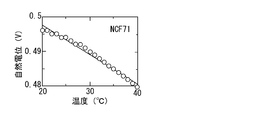
- FIG. 6 is an explanatory diagram of the experimental results of Experimental Example 3-1, in which the horizontal axis represents temperature and the vertical axis represents natural potential.
- the temperature dependence of the natural potential was measured in the same manner as in Experimental Examples 1-1 and 1-2. The experimental results are shown in FIG. In FIG. 6, it was confirmed that the natural potential decreased at ⁇ 0.85 [mV / degree] with increasing temperature.
- FIG. 7 is an explanatory diagram of the experimental results of Experimental Example 3-2, in which the horizontal axis represents temperature and the vertical axis represents thermoelectromotive force.
- each NCF71 thin film was immersed in a 1 [M] NaCl aqueous solution, and the electromotive force was measured. The room temperature at this time was 20 degrees.
- the experimental results are shown in FIG. In FIG. 7, the electromotive force of the thin film increased at a rate of ⁇ 0.7 [mV / degree] with the temperature rise of the aqueous solution in the first tank 3a taken on the horizontal axis of the graph.
- thermoelectromotive force of about 1 [mV / degree] was obtained near room temperature. Therefore, for example, by increasing the number of negative electrodes 6, increasing the number of pairs of electrodes 6 and 7, and connecting them in series, a relatively large electromotive force can be generated near room temperature. .
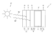
- FIG. 8 is an explanatory diagram of the thermoelectric conversion element of the second embodiment, and corresponds to FIG. 1 of the first embodiment.
- components corresponding to those of the first embodiment are denoted by the same reference numerals, and detailed description thereof is omitted.
- the second embodiment is different from the first embodiment in the following points, but is configured in the same manner as the first embodiment in other points.
- a pair of electrodes 6 ′ and 7 ′ are arranged opposite to the left and right sides of the electrolyte tank 3 ′ in which the electrolyte 2 is accommodated.
- Surface layers 6b 'and 7b' constructed in the same manner as in Example 1 are disposed on the surface of each electrode 6 'and 7' on the electrolyte tank 3 'side, and the surface layers 6b' and 7b 'are in contact with the electrolyte 2. is doing.
- a solar cell 11 as an example of a power generation element is supported on the negative electrode 6 ′ of Example 2 as an example of a heated and cooled part on the surface opposite to the electrolyte tank 3 ′.
- the solar cell 11 is a conventionally known power generation element, and includes an anode 12 made of a p-type semiconductor and a cathode 13 made of an n-type semiconductor. And in Example 2, it replaces with the heat source 8 of Example 1, and uses the sun 8 'as an example of a heat source.
- Example 2 (Operation of Example 2)
- the solar cell 11 generates power with the ultraviolet rays 8a ′ included in the sunlight, and the negative electrode 6 is heated with the infrared rays 8b ′ included in the sunlight. Therefore, a temperature difference is generated between the electrodes 6 'and 7' as the infrared ray 8b 'is heated, and a thermoelectromotive force is generated as in the battery 1 of the first embodiment. Therefore, the composite battery 1 ′ of the second embodiment can generate power using sunlight from the sun 8 ′ as an example of a heat source.
- Example 2 when the temperature difference is generated between the electrodes 6 'and 7', the infrared ray 8b having a wavelength different from that of the ultraviolet ray 8a used in the solar cell 11 is mainly used, and the sunlight is efficiently used. It can be used well.
- the electrodes 6 'and 7' of the battery 1 'and the electrodes 12 and 13 of the solar battery 11 can be connected in any manner, either in series or in parallel.
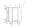
- FIG. 9 is an explanatory diagram of the thermoelectric conversion element according to the third embodiment of the present invention, and corresponds to FIG. 1 according to the first embodiment.
- components corresponding to those of the first and second embodiments are denoted by the same reference numerals, and detailed description thereof is omitted.
- the third embodiment is different from the first and second embodiments in the following points, but is configured in the same manner as the first and second embodiments in other points.
- a battery 1 ′′ as an example of the thermoelectric conversion element of Example 3 has an electrolyte tank 3 ′ and electrodes 6 ′ and 7 ′ configured in the same manner as Example 2, and the solar cell of Example 2 11 is supported by a heat flow path 21.
- a fluid from a heat generation section (not shown) connected to the outside is introduced into the heat flow path 21 from an introduction section 21a at the upper end, and from a discharge section 21b at the lower end. Discharged.
- the automobile engine can be used as the heat generation unit, and the fluid heated by the waste heat generated by the automobile engine can be introduced into the heat passage 21.
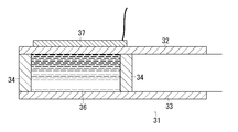
- FIG. 10 is an explanatory diagram of a thermoelectric conversion element according to the fourth embodiment of the present invention, and corresponds to FIG.
- the thermoelectric conversion element 31 of Example 4 has a pair of first electrode 32 and second electrode 33 made of lithium cobalt oxide (LiCoO 2 ) as an example of an active material.
- the electrodes 32 and 33 are arranged with a space therebetween, and the electrodes 32 and 33 are partitioned by a pair of wall members 34.
- the electrolyte solution 36 is accommodated in the space surrounded by the electrodes 32 and 33 and the wall member 34.
- a heater 37 as an example of a heat source is in contact with the first electrode 32, and the first electrode 32 is a heated and cooled part.
- LiCoO 2 powder was mixed with a binder and carbon black to prepare a slurry, and this slurry was applied onto an aluminum foil and dried at 120 ° C. for 2 hours to form an electrode.
- the electrodes 32 and 33 are referred to as “LCO electrodes”.
- the wall member 34 of Example 4 was comprised by the polytetrafluoroethylene (PTFE), material is not limited to this, It can change into the arbitrary materials which can be used.
- Example 4 perchlorine containing lithium ions (Li + ) as an example of alkali metal ions in a solvent (EC + DEC solution) in which ethylene carbonate and diethyl carbonate were mixed at a volume ratio of 1: 1.
- EC + DEC solution a solvent in which ethylene carbonate and diethyl carbonate were mixed at a volume ratio of 1: 1.
- a solution in which 1 mol of lithium acid (LiClO 4 ) was dissolved was used as an example of the electrolyte solution 36.
- thermoelectric conversion element 31 of Example 4 having the above-described configuration, the oxidation reaction shown in the following formula (4) and the reduction shown in the formula (5) are performed when the first electrode 32 is not heated by the heater 37.
- the reaction is balanced and no current flows.
- the first electrode 32 is heated by the heater 37, a temperature difference is generated between the electrodes 32 and 33, and the equilibrium state is lost.
- the LCO electrode when the temperature increases, the rate of the oxidation reaction increases, and the first electrode 32 becomes the negative electrode and the second electrode 33 becomes the positive electrode.
- thermoelectric conversion element 31 of the fourth embodiment a thermoelectromotive force is generated due to the oxidation-reduction reaction at the electrodes 32 and 33 as in the first to third embodiments.
- Example 4 it is possible to use an electrode of lithium cobaltate that is used as a positive electrode in a conventionally known lithium ion battery, an existing production facility can be used, and an increase in cost is suppressed. be able to. Further, unlike the prior art, it is not necessary to use an expensive electrode such as a platinum (Pt) electrode, and the cost can be reduced. Further, in the thermoelectric conversion element 31 of Example 4, as in Examples 1 to 3, the active material is present in the electrodes 32 and 33 that are solid, and in a solution in which the active material is liquid as in the prior art.
- the density of the active material is higher than the structure existing in Therefore, in the thermoelectric conversion element 31 of Example 4, the efficiency of thermoelectric conversion is improved as compared with the conventional configuration in which the density of the active material is low, and a high-density active material is used without using a low-density solution. Therefore, even if it is thin and downsized, the same output can be obtained. Moreover, in the thermoelectric conversion element 31 of Example 4, the material which does not melt
- FIG. 11 is an explanatory diagram of the measurement apparatus of Experimental Example 4.
- the electrodes 32 and 33 and the electrolyte solution 36 of Example 4 were used.
- a rotor 41 that stirs the electrolyte solution 36 is disposed in the electrolyte solution 36.
- a voltmeter is connected between the electrodes 32 and 33 to measure the potential difference ⁇ V
- a thermocouple 42 is connected between the electrodes 32 and 33 so that a temperature difference ⁇ T between the electrodes 32 and 33 is also obtained. It was measured.
- FIG. 12 is an explanatory diagram of the experimental results of Experimental Example 4, and is a graph with the temperature difference on the horizontal axis and the potential difference on the vertical axis.
- Experimental Example 4-1 by supplying current to the heater 37 with the rotor 41 stopped, a temperature difference ⁇ T was generated, and a maximum temperature difference of 13.5 [K] was generated. The potential difference ⁇ V was measured when the temperature difference ⁇ T was 4.5 [K], 7 [K], or 13.5 [K]. The experimental results are indicated by black circles ( ⁇ ) in FIG.
- Experimental Example 4-2 with the rotor 41 rotated, current was supplied to the heater 37 to generate the temperature difference ⁇ T, and a maximum temperature difference of 12 [K] was generated. The potential difference ⁇ V was measured when the temperature difference ⁇ T was 4.5 [K], 6 [K], 9 [K], and 12 [K]. The experimental results are shown by the squares ( ⁇ ) in FIG.
- thermoelectric conversion element 31 of Example 4 can produce a highly efficient thermoelectric conversion element as compared with a conventionally known Peltier element.
- the cause of the decrease in Seebeck coefficient in Experimental Example 4-3 is that an LCO electrode without lithium deficiency, that is, an uncharged LCO electrode, is less likely to cause a redox reaction, but is naturally occurring at the LCO electrode. This may be due to a small amount of lithium deficiency or the spontaneous introduction of lithium ions when the LCO electrode is immersed in the electrolyte solution.
- FIG. 13 is an explanatory diagram of the thermoelectric conversion element according to the fifth embodiment of the present invention, and corresponds to FIG.
- components corresponding to those of the first to fourth embodiments are denoted by the same reference numerals, and detailed description thereof is omitted.
- the fifth embodiment is different from the first to fourth embodiments in the following points, but is configured in the same manner as the first to fourth embodiments in other points.
- 13 in the battery 51 as an example of the thermoelectric conversion element of Example 5 a total of 10 layers of electrodes 52-1, 52-2, 52-3,..., 52-10 are parallel and spaced apart. Is arranged.
- the electrode 52-1 to the electrode 52-10 of the fifth embodiment employ a configuration in which lithium cobalt oxide (LiCoO 2 ) is applied to the surface of the aluminum foil.
- an active material layer 54 coated with lithium cobalt oxide is formed on one surface of the aluminum foil 53, and the second-layer electrode 52 is formed.
- an active material layer 54 in which lithium cobaltate is applied on both surfaces of an aluminum foil 53 is formed.
- the first and tenth layer electrodes 52-1 and 52-10 are configured in the same manner as the second to ninth layer electrodes 52-2 to 52-9.
- a separator 56 as an example of a holding member is disposed between the electrodes 52-1 to 52-10.
- the separator 56 a separator used in a conventionally known battery is used.
- the separator 56 holds an electrolyte solution.
- layers of the electrolyte solutions 57 and 58 are schematically illustrated between the separator 56 and the electrodes 52-1 to 52-10 sandwiching both sides thereof. .
- As the electrolyte solutions 57 and 58 of Example 5 a solution in which 1 mol of lithium perchlorate (LiClO 4 ) is dissolved in an EC + DEC solution is used.
- Example 5 the outer sides of the electrodes 52-1 to 52-10 and the separator 56 are covered with a film 59 as an example of an exterior member, and the first layer 52-1 and the tenth layer are covered.
- a conductive wire 61 is connected to the electrode 52-10.
- a high-temperature hot bath 62 having a preset temperature TH is disposed in contact with the outside of the first-layer electrode 52-1 as an example of the portion to be cooled.
- a low temperature heat bath 63 having a preset temperature TL lower than the temperature TH of the high temperature heat bath 62 is disposed in contact with the outside of the tenth layer electrode 52-10 as an example of the temperature-cooled portion. ing.
- the temperatures T1, T2,..., T10 of the electrodes 52-1, 52-2,..., 52-10 of the fifth embodiment are naturally caused by the temperature difference between the temperatures TH, TL of the heat baths 62, 63.
- FIG. 14 is an explanatory diagram of a module in which the thermoelectric conversion elements of Example 5 are connected in series.
- the battery module 71 of Example 5 three batteries 51 are electrically connected in series. That is, as shown in FIG. 14, the conductor 61 of the first layer electrode 52-1 of the second battery 51B is connected to the tenth layer electrode 52-10 of the third battery 51C, and the second The conducting wire 61 of the tenth layer electrode 52-10 of the battery 51B is connected to the first layer electrode 52-1 of the first battery 51A.
- the batteries 51A to 51C are in contact with a common high temperature heat bath 62 and low temperature heat bath 63.
- Example 5 (Operation of Example 5)
- the active material layers 54 of the respective electrodes 52-1 to 52-10 are arranged to face each other with the electrolyte solution 57, 58 held in the separator 56 interposed therebetween.
- the temperature difference between the electrodes is ideally (TH-TL), but the actual temperature difference depends on the thermal resistance, etc. It becomes smaller than the temperature difference (TH-TL).
- the thermal resistance can be increased by increasing the number of layers, and the first layer electrode 52-1 and the tenth layer electrode 52-
- the temperature difference ⁇ T generated with respect to 10 approaches TH ⁇ TL. That is, the temperature difference approaches the ideal value, and the generated potential difference ⁇ V can be increased, thereby improving the efficiency.
- the voltage generated can be increased by connecting the batteries 51 in series, and the voltage of V order is generated instead of mV order by increasing the number of the batteries 51. It is also possible to make it.
- the sixth embodiment is different from the first to fifth embodiments in the following points, but is configured in the same manner as the first to fifth embodiments in other points.
- the battery as an example of the thermoelectric conversion element of Example 6 employs an electrode using carbon (graphite, C 6 ) as an example of an active material instead of the electrode using lithium cobalt oxide of Example 4. Since the configuration is the same except for the electrodes, detailed description is omitted. That is, in Example 6, the same electrolytic solution, heater, etc. as in Example 4 are used.
- the electrode of Example 6 was prepared by mixing carbon powder together with a binder in the same manner as in Example 4 to prepare a slurry, applying the slurry on an aluminum foil, and drying at 120 ° C. for 2 hours. did.
- this electrode is referred to as “C electrode”.
- the electrode that caused the introduction of lithium as shown in the following formula (6) was used for the C electrode. That is, as in Example 4, the C electrode and the lithium metal electrode were immersed in an EC + DEC solution in which 1 mol of lithium perchlorate had been dissolved so that the C electrode became a positive electrode and the lithium metal became a negative electrode.
- lithium ions Li + which are alkali metal ions having a very small molecular weight and a high moving speed, move. Therefore, in the battery of Example 6, as in Examples 1 to 5, a thermoelectromotive force is generated due to the oxidation-reduction reaction at the electrodes (32, 33).
- Example 6 Next, an experiment for confirming the effect of Example 6 was performed.
- Example 6 In Experimental Example 6, the same experimental apparatus as in Example 4 was used to measure the potential difference ⁇ V between the electrodes and the temperature difference ⁇ T between the electrodes.
- FIG. 15 is an explanatory diagram of the experimental results of Experimental Example 6, in which the horizontal axis indicates the temperature difference and the vertical axis indicates the potential difference.
- the temperature difference ⁇ T is generated by supplying current to the heater 37 with the rotor 41 stopped, and a maximum of 20 [K] is generated. Some degree of temperature difference was generated. Note that the measurement was performed on two different samples, and the potential difference ⁇ V was measured when the temperature difference ⁇ T was 5 [K], 10 [K], 12.5 [K], 16 [K], 20 [K]. , 21 [K]. The experimental results are shown in FIG.
- thermoelectric conversion element of Example 6 can produce a highly efficient thermoelectric conversion element as compared with a conventionally known Peltier element.
- Example 6-2 In Experimental Example 6-2, similar to Experimental Example 4-3, the Seebeck coefficient was measured twice using a C electrode that did not discharge (that is, an electrode without lithium introduction). In each measurement, when a temperature difference of 12.5 [K] and 17.8 [K] was generated between the electrodes, ⁇ 13.2 [mV] and ⁇ 12.8 [mV] were measured. From this, the Seebeck coefficient was estimated to be ⁇ 1.06 [mV / K] and ⁇ 0.72 [mV / K]. This is about half that of Example 6-1 but about four times higher than that of the conventional bismuth tellurium system.
- the electrolytes exemplified in the experimental examples are not limited to those exemplified, and an electrolyte containing any alkali metal ion can be used.
- an electrolyte containing any alkali metal ion can be used.
- Li + ions as an example of alkali metal ions
- the positive electrode and the negative electrode can be arranged in multiple layers in a multi-stage, and it is possible to reduce the size and increase the capacity and voltage.
- low-cost element development can be sufficiently performed using a known technique, and thermal power generation and solar thermal power generation near room temperature can be expected.
- the cyano bridged metal complex is not limited to the configuration exemplified in the experimental example, and A is at least one alkali metal, M is at least one transition metal, L Is at least one kind of transition metal, x is a number greater than 0 and less than or equal to 2, y is a number greater than 0 and less than or equal to 1, and z is a number greater than 0 and less than or equal to 14, the chemical formula A x M [L (CN) 6 ] A cyano-bridged metal complex represented by y ⁇ nH 2 O can be used.
- the alkali metal of A include Li, Na, K, Rb, and Cs.
- Examples of the M transition metal include Fe, Mn, Ni, Co, Cr, V, Cu, and Zn.
- Examples of the transition metal of L include Fe, Cr, V, Mn, and Ti.
- X, y, and z represent the ratio (mole) of alkali metal A, L (CN) 6 , and crystal water H 2 O to 1 mol of transition metal M, respectively.
- x can take values from 0 to 2, y from 0 to 1, and z from 0 to 14.
- “complexes having different compositions” refer to those in which at least one of alkali metal A, transition metals M and L, and numbers x and y are different.
- thermoelectric conversion element in the above embodiment, when current is extracted to the outside, sodium ions and lithium ions move, and so to speak, charging occurs, so that it is not possible to extract current infinitely.
- the power generation efficiency decreases with time. Therefore, the process of monitoring the electromotive force and the temperature difference between the electrodes and discharging the inside, for example, the process of flowing a current reversely or heating the reverse electrode automatically and periodically is executed. In this way, the performance as a battery can be maintained.
- the electric power is generated by connecting to the electric storage element, the electric storage element is charged, and when the electromotive force is lowered, the electric current is received from the electric storage element to discharge the batteries 1, 1 ′, 1 ′′, 31, 51. It is also possible.
- the electromotive force due to the temperature gradient is in a state where the electromotive force due to the difference in the concentration of lithium ions and sodium ions is canceled, and the net electromotive force is lost.
- the electromotive force due to the concentration difference can be taken out by removing the temperature gradient, that is, removing the solar heat and the heat bath.
- an electromotive force due to the concentration difference is taken out, an electrode discharge occurs. Therefore, if a temperature gradient is applied after the electromotive force due to the concentration difference is taken out, it can be expected to perform thermoelectric generation again.
- thermoelectric conversion element of the present invention can be used as an electric power system integrated with a Peltier element that induces a temperature difference by applying a voltage, a thermoelectric generation element, a solar thermal generation element, or a storage element.
- thermoelectric conversion element of the present invention can be realized as an inexpensive and thin thermoelectric conversion element, and is used as a portable (portability, portable) or wearable (wearable, wearable) thermoelectric generation element. It is possible. Furthermore, it can also be used as a portable or wearable thermal charging element.
- thermoelectric conversion element 1, 1 ', 1 ", 31, 51 ... thermoelectric conversion element, 2, 36, 57, 58 ... electrolyte, 3a, 6 ', 32, 52-1, 52-10 ... heated and cooled part, 6, 6 ', 32, 52-1 to 52-9 ... the first electrode, 6a, 7a ... substrate, 6b, 7b, 6b ', 7b' ... cyano bridged metal complex, 7, 7 ', 52-2 to 52-10, second electrode.
Landscapes
- Chemical & Material Sciences (AREA)
- Chemical Kinetics & Catalysis (AREA)
- Electrochemistry (AREA)
- General Chemical & Material Sciences (AREA)
- Hybrid Cells (AREA)
Abstract
L'invention concerne une technique de conversion thermoélectrique compacte, peu coûteuse et hautement efficace qui est réalisée par un procédé de conversion thermoélectrique dans lequel est utilisée une réaction d'oxydoréduction, le procédé étant caractérisé en ce qu'une première électrode (6) contenant un matériau actif, et une deuxième électrode (7) contenant le même matériau actif que la première électrode (6) sont mises en contact avec un électrolyte (2) contenant des ions de métal alcalin ; la première électrode (6) ou la deuxième électrode (7) est chauffée ou refroidie, une différence de température étant ainsi générée entre la première électrode (6) et la deuxième électrode (7) ; et une force thermoélectromotrice provoquée par une réaction d'oxydoréduction dans chacune des électrodes (6, 7) est générée.
Priority Applications (1)
| Application Number | Priority Date | Filing Date | Title |
|---|---|---|---|
| JP2013509779A JP5988172B2 (ja) | 2011-04-12 | 2012-04-05 | 酸化還元反応を利用した熱電変換方法および熱電変換素子 |
Applications Claiming Priority (4)
| Application Number | Priority Date | Filing Date | Title |
|---|---|---|---|
| JP2011-088683 | 2011-04-12 | ||
| JP2011088683 | 2011-04-12 | ||
| JP2011-220060 | 2011-10-04 | ||
| JP2011220060 | 2011-10-04 |
Publications (1)
| Publication Number | Publication Date |
|---|---|
| WO2012140856A1 true WO2012140856A1 (fr) | 2012-10-18 |
Family
ID=47009051
Family Applications (1)
| Application Number | Title | Priority Date | Filing Date |
|---|---|---|---|
| PCT/JP2012/002391 Ceased WO2012140856A1 (fr) | 2011-04-12 | 2012-04-05 | Procédé de conversion thermoélectrique et élément de conversion thermoélectrique dans lequel est utilisée la réaction d'oxydoréduction |
Country Status (2)
| Country | Link |
|---|---|
| JP (1) | JP5988172B2 (fr) |
| WO (1) | WO2012140856A1 (fr) |
Cited By (19)
| Publication number | Priority date | Publication date | Assignee | Title |
|---|---|---|---|---|
| WO2015160151A1 (fr) * | 2014-04-17 | 2015-10-22 | 부산대학교 산학협력단 | Dispositif thermoélectrique et système thermoélectrique comprenant ce dernier |
| WO2015160150A1 (fr) * | 2014-04-17 | 2015-10-22 | 부산대학교 산학협력단 | Solution d'électrolyte pour un dispositif thermoélectrique, et dispositif thermoélectrique comprenant celle-ci |
| KR20150120284A (ko) * | 2014-04-17 | 2015-10-27 | 부산대학교 산학협력단 | 열전 장치용 전해질 용액 및 이를 포함하는 열전 장치 |
| WO2017038988A1 (fr) * | 2015-09-04 | 2017-03-09 | 国立大学法人東京工業大学 | Élément de génération d'énergie thermoélectrique, module de génération d'énergie thermoélectrique le comprenant et procédé de génération d'énergie thermoélectrique l'utilisant |
| KR101747165B1 (ko) * | 2015-10-12 | 2017-06-14 | 부산대학교 산학협력단 | 열전기화학 전지 시스템 |
| KR101755228B1 (ko) * | 2015-09-11 | 2017-07-07 | 부산대학교 산학협력단 | 열전기화학 전지 시스템 |
| JP2018073596A (ja) * | 2016-10-28 | 2018-05-10 | 国立大学法人 筑波大学 | 熱発電素子 |
| WO2020031992A1 (fr) * | 2018-08-06 | 2020-02-13 | 国立大学法人東京工業大学 | Batterie de génération d'énergie utilisant de la chaleur et procédé de génération d'énergie utilisant de la chaleur l'utilisant |
| WO2020262165A1 (fr) * | 2019-06-26 | 2020-12-30 | 三桜工業株式会社 | Module de génération thermoélectrique |
| WO2020262164A1 (fr) * | 2019-06-26 | 2020-12-30 | 三桜工業株式会社 | Module de génération d'énergie utilisant de la chaleur et dispositif de génération d'énergie thermique équipé de celui-ci |
| WO2020262171A1 (fr) * | 2019-06-26 | 2020-12-30 | 三桜工業株式会社 | Module de production d'énergie utilisant la chaleur |
| CN112713233A (zh) * | 2019-10-25 | 2021-04-27 | 南方科技大学 | 准固态离子型热电转换材料、热电转换器件及其应用 |
| CN113388845A (zh) * | 2021-06-11 | 2021-09-14 | 四川大学 | 微生物-光电化学-热电化学耦合产氢系统 |
| EP3818585A4 (fr) * | 2018-07-06 | 2022-03-30 | The Government of the United States of America, as represented by the Secretary of the Navy | Déclencheur de court-circuit interne de batterie et procédé de performance améliorée |
| US11346103B2 (en) * | 2018-10-18 | 2022-05-31 | Arizona Board Of Regents On Behalf Of Arizona State University | Systems and methods for a power-generating thermogalvanic brick |
| JPWO2022191101A1 (fr) * | 2021-03-08 | 2022-09-15 | ||
| WO2022239856A1 (fr) * | 2021-05-14 | 2022-11-17 | 国立大学法人東京工業大学 | Appareil de conversion thermoélectrique et complexe métallique de cobalt |
| EP3993255A4 (fr) * | 2019-06-26 | 2023-08-23 | Sanoh Industrial Co., Ltd. | Dispositif de génération thermoélectrique |
| TWI921303B (zh) | 2019-06-26 | 2026-04-11 | 日商三櫻工業股份有限公司 | 利用熱之發電模組 |
Families Citing this family (1)
| Publication number | Priority date | Publication date | Assignee | Title |
|---|---|---|---|---|
| KR102711707B1 (ko) * | 2021-06-30 | 2024-09-30 | 포항공과대학교 산학협력단 | 열전기화학 전지 시스템 |
Citations (5)
| Publication number | Priority date | Publication date | Assignee | Title |
|---|---|---|---|---|
| JPS60243979A (ja) * | 1984-05-18 | 1985-12-03 | Toho Rayon Co Ltd | 温度差電池 |
| JPH05144483A (ja) * | 1991-11-19 | 1993-06-11 | Nippon Telegr & Teleph Corp <Ntt> | 温度差電池 |
| JPH09259944A (ja) * | 1996-03-22 | 1997-10-03 | Nippon Telegr & Teleph Corp <Ntt> | 温度差電池 |
| WO2001071821A1 (fr) * | 2000-03-24 | 2001-09-27 | Shin-Etsu Chemical Co., Ltd. | Generateur thermoelectrique |
| JP2010114349A (ja) * | 2008-11-10 | 2010-05-20 | Konica Minolta Holdings Inc | 複合発電装置 |
-
2012
- 2012-04-05 JP JP2013509779A patent/JP5988172B2/ja active Active
- 2012-04-05 WO PCT/JP2012/002391 patent/WO2012140856A1/fr not_active Ceased
Patent Citations (5)
| Publication number | Priority date | Publication date | Assignee | Title |
|---|---|---|---|---|
| JPS60243979A (ja) * | 1984-05-18 | 1985-12-03 | Toho Rayon Co Ltd | 温度差電池 |
| JPH05144483A (ja) * | 1991-11-19 | 1993-06-11 | Nippon Telegr & Teleph Corp <Ntt> | 温度差電池 |
| JPH09259944A (ja) * | 1996-03-22 | 1997-10-03 | Nippon Telegr & Teleph Corp <Ntt> | 温度差電池 |
| WO2001071821A1 (fr) * | 2000-03-24 | 2001-09-27 | Shin-Etsu Chemical Co., Ltd. | Generateur thermoelectrique |
| JP2010114349A (ja) * | 2008-11-10 | 2010-05-20 | Konica Minolta Holdings Inc | 複合発電装置 |
Non-Patent Citations (1)
| Title |
|---|
| TERUKI MOTOHASHI ET AL.: "Sojo Cobalt Sankabutsu LixCo02(4): Netsuden Henkan Tokusei to Denshi Kozo", DAI 57 KAI EXTENDED ABSTRACTS, March 2010 (2010-03-01), pages 09 - 075 * |
Cited By (48)
| Publication number | Priority date | Publication date | Assignee | Title |
|---|---|---|---|---|
| US10305013B2 (en) | 2014-04-17 | 2019-05-28 | Pusan National University Industry University Cooperation Foundation Of Pusan | Electrolyte solution for thermoelectric device and thermoelectric device including the electrolyte solution |
| WO2015160150A1 (fr) * | 2014-04-17 | 2015-10-22 | 부산대학교 산학협력단 | Solution d'électrolyte pour un dispositif thermoélectrique, et dispositif thermoélectrique comprenant celle-ci |
| KR20150120284A (ko) * | 2014-04-17 | 2015-10-27 | 부산대학교 산학협력단 | 열전 장치용 전해질 용액 및 이를 포함하는 열전 장치 |
| KR101574012B1 (ko) | 2014-04-17 | 2015-12-02 | 부산대학교 산학협력단 | 열전 장치 및 이를 포함하는 열전 시스템 |
| KR101691946B1 (ko) * | 2014-04-17 | 2017-01-02 | 부산대학교 산학협력단 | 열전 장치용 전해질 용액 및 이를 포함하는 열전 장치 |
| US20170062689A1 (en) * | 2014-04-17 | 2017-03-02 | Pusan National University Industry-University Cooperration Foundation | Thermoelectric device and thermoelectric system including the device |
| WO2015160151A1 (fr) * | 2014-04-17 | 2015-10-22 | 부산대학교 산학협력단 | Dispositif thermoélectrique et système thermoélectrique comprenant ce dernier |
| JPWO2017038988A1 (ja) * | 2015-09-04 | 2018-06-21 | 国立大学法人東京工業大学 | 熱電発電素子及びそれを含む熱電発電モジュール、並びにそれを用いた熱電発電方法 |
| WO2017038988A1 (fr) * | 2015-09-04 | 2017-03-09 | 国立大学法人東京工業大学 | Élément de génération d'énergie thermoélectrique, module de génération d'énergie thermoélectrique le comprenant et procédé de génération d'énergie thermoélectrique l'utilisant |
| KR101755228B1 (ko) * | 2015-09-11 | 2017-07-07 | 부산대학교 산학협력단 | 열전기화학 전지 시스템 |
| KR101747165B1 (ko) * | 2015-10-12 | 2017-06-14 | 부산대학교 산학협력단 | 열전기화학 전지 시스템 |
| JP2018073596A (ja) * | 2016-10-28 | 2018-05-10 | 国立大学法人 筑波大学 | 熱発電素子 |
| EP3818585A4 (fr) * | 2018-07-06 | 2022-03-30 | The Government of the United States of America, as represented by the Secretary of the Navy | Déclencheur de court-circuit interne de batterie et procédé de performance améliorée |
| US12424669B2 (en) | 2018-07-06 | 2025-09-23 | The Government Of The United States Of America, As Represented By The Secretary Of The Navy | Methods for battery internal short circuit trigger and improved performance by temperature gradients |
| US11758814B2 (en) | 2018-08-06 | 2023-09-12 | Tokyo Institute Of Technology | Heat-utilizing power generation battery and heat-utilizing power generation method using same |
| JP7329517B2 (ja) | 2018-08-06 | 2023-08-18 | 国立大学法人東京工業大学 | 熱利用発電池、及びそれを用いた熱利用発電方法 |
| TWI803679B (zh) * | 2018-08-06 | 2023-06-01 | 國立大學法人東京工業大學 | 熱力發電電池,及使用此之熱力發電方法 |
| WO2020031992A1 (fr) * | 2018-08-06 | 2020-02-13 | 国立大学法人東京工業大学 | Batterie de génération d'énergie utilisant de la chaleur et procédé de génération d'énergie utilisant de la chaleur l'utilisant |
| CN112689907A (zh) * | 2018-08-06 | 2021-04-20 | 国立大学法人东京工业大学 | 热利用发电电池及使用该热利用发电电池的热利用发电法 |
| JPWO2020031992A1 (ja) * | 2018-08-06 | 2021-08-12 | 国立大学法人東京工業大学 | 熱利用発電池、及びそれを用いた熱利用発電方法 |
| US11346103B2 (en) * | 2018-10-18 | 2022-05-31 | Arizona Board Of Regents On Behalf Of Arizona State University | Systems and methods for a power-generating thermogalvanic brick |
| CN114026706A (zh) * | 2019-06-26 | 2022-02-08 | 三樱工业株式会社 | 热利用发电模块 |
| JP7637936B2 (ja) | 2019-06-26 | 2025-03-03 | 三桜工業株式会社 | 熱利用発電モジュール及びそれを備える熱発電装置 |
| CN113994488A (zh) * | 2019-06-26 | 2022-01-28 | 三樱工业株式会社 | 热利用发电模块及具备其的热发电装置 |
| TWI921303B (zh) | 2019-06-26 | 2026-04-11 | 日商三櫻工業股份有限公司 | 利用熱之發電模組 |
| JP2021005651A (ja) * | 2019-06-26 | 2021-01-14 | 三桜工業株式会社 | 熱利用発電モジュール |
| JP2021005650A (ja) * | 2019-06-26 | 2021-01-14 | 三桜工業株式会社 | 熱利用発電モジュール |
| CN113994488B (zh) * | 2019-06-26 | 2026-03-17 | 三樱工业株式会社 | 热利用发电模块及具备其的热发电装置 |
| JP7780605B2 (ja) | 2019-06-26 | 2025-12-04 | 三桜工業株式会社 | 熱利用発電モジュール |
| US20220359805A1 (en) * | 2019-06-26 | 2022-11-10 | Sanoh Industrial Co., Ltd. | Heat-utilizing power generation module and thermal power generation device equipped with same |
| WO2020262165A1 (fr) * | 2019-06-26 | 2020-12-30 | 三桜工業株式会社 | Module de génération thermoélectrique |
| JP2021005649A (ja) * | 2019-06-26 | 2021-01-14 | 三桜工業株式会社 | 熱利用発電モジュール及びそれを備える熱発電装置 |
| EP3968392A4 (fr) * | 2019-06-26 | 2023-07-12 | Sanoh Industrial Co., Ltd. | Module de génération d'énergie utilisant de la chaleur et dispositif de génération d'énergie thermique équipé de celui-ci |
| WO2020262171A1 (fr) * | 2019-06-26 | 2020-12-30 | 三桜工業株式会社 | Module de production d'énergie utilisant la chaleur |
| EP3993255A4 (fr) * | 2019-06-26 | 2023-08-23 | Sanoh Industrial Co., Ltd. | Dispositif de génération thermoélectrique |
| WO2020262164A1 (fr) * | 2019-06-26 | 2020-12-30 | 三桜工業株式会社 | Module de génération d'énergie utilisant de la chaleur et dispositif de génération d'énergie thermique équipé de celui-ci |
| US12389795B2 (en) | 2019-06-26 | 2025-08-12 | Sanoh Industrial Co. , Ltd. | Heat-utilizing power generation module |
| US12150382B2 (en) | 2019-06-26 | 2024-11-19 | Sanoh Industrial Co., Ltd. | Thermoelectric generation module |
| JP2024174112A (ja) * | 2019-06-26 | 2024-12-13 | 三桜工業株式会社 | 熱利用発電モジュール |
| JP7627082B2 (ja) | 2019-06-26 | 2025-02-05 | 三桜工業株式会社 | 熱利用発電モジュール |
| US12310238B2 (en) * | 2019-06-26 | 2025-05-20 | Sanoh Industrial Co., Ltd. | Heat-utilizing power generation module and thermal power generation device equipped with same |
| US12289997B2 (en) * | 2019-06-26 | 2025-04-29 | Sanoh Industrial Co., Ltd. | Heat-utilizing power generation module and thermal power generation device equipped with same |
| CN112713233B (zh) * | 2019-10-25 | 2023-09-26 | 南方科技大学 | 准固态离子型热电转换材料、热电转换器件及其应用 |
| CN112713233A (zh) * | 2019-10-25 | 2021-04-27 | 南方科技大学 | 准固态离子型热电转换材料、热电转换器件及其应用 |
| WO2022191101A1 (fr) * | 2021-03-08 | 2022-09-15 | 国立大学法人東京工業大学 | Élément de production d'énergie thermoélectrique, batterie de production d'énergie thermoélectrique et procédé de stabilisation de production d'énergie |
| JPWO2022191101A1 (fr) * | 2021-03-08 | 2022-09-15 | ||
| WO2022239856A1 (fr) * | 2021-05-14 | 2022-11-17 | 国立大学法人東京工業大学 | Appareil de conversion thermoélectrique et complexe métallique de cobalt |
| CN113388845A (zh) * | 2021-06-11 | 2021-09-14 | 四川大学 | 微生物-光电化学-热电化学耦合产氢系统 |
Also Published As
| Publication number | Publication date |
|---|---|
| JP5988172B2 (ja) | 2016-09-07 |
| JPWO2012140856A1 (ja) | 2014-07-28 |
Similar Documents
| Publication | Publication Date | Title |
|---|---|---|
| JP5988172B2 (ja) | 酸化還元反応を利用した熱電変換方法および熱電変換素子 | |
| Gao et al. | Thermally regenerative electrochemical cycle for low-grade heat harvesting | |
| Cheng et al. | Insights into the thermopower of thermally regenerative electrochemical cycle for low grade heat harvesting | |
| Ding et al. | Simultaneous energy harvesting and storage via solar-driven regenerative electrochemical cycles | |
| Li et al. | 3D Hierarchical Electrodes Boosting Ultrahigh Power Output for Gelatin‐KCl‐FeCN4−/3− Ionic Thermoelectric Cells | |
| Liu et al. | Lithium manganese oxide in an aqueous electrochemical system for low-grade thermal energy harvesting | |
| Feng et al. | Advances and challenges in photoelectrochemical redox batteries for solar energy conversion and storage | |
| Dupont et al. | Thermo-electrochemical cells for waste heat harvesting–progress and perspectives | |
| JP6803076B2 (ja) | 熱電発電素子及びそれを含む熱電発電モジュール、並びにそれを用いた熱電発電方法 | |
| Poletayev et al. | Continuous electrochemical heat engines | |
| Reed et al. | Performance of Nafion® N115, Nafion® NR-212, and Nafion® NR-211 in a 1 kW class all vanadium mixed acid redox flow battery | |
| Li et al. | Continuous thermally regenerative electrochemical systems for directly converting low-grade heat to electricity | |
| Zhang et al. | Copper foam electrodes for increased power generation in thermally regenerative ammonia-based batteries for low-grade waste heat recovery | |
| Cheng et al. | Review of liquid-based systems to recover low-grade waste heat for electrical energy generation | |
| Zhu et al. | Ultra-high performance of ionic thermoelectric-electrochemical gel cells for harvesting low grade heat | |
| Kazim et al. | Thermo-electrochemical generator: energy harvesting & thermoregulation for liquid cooling applications | |
| Zhang et al. | Efficient low‐grade heat conversion and storage with an activity‐regulated redox flow cell via a thermally regenerative electrochemical cycle | |
| JP6732227B2 (ja) | 熱化学電池 | |
| JP7526483B2 (ja) | 熱電池 | |
| Bicer et al. | Performance assessment of electrochemical ammonia synthesis using photoelectrochemically produced hydrogen | |
| Meng et al. | A thermally chargeable hybrid supercapacitor with high power density for directly converting heat to electricity | |
| CN116053511B (zh) | 周期性低品位热能高效回收转换系统及方法 | |
| JP6908256B2 (ja) | 熱発電素子 | |
| Tehrani et al. | Application of electrodeposited cobalt hexacyanoferrate film to extract energy from water salinity gradients | |
| Yang et al. | Energy Density in Ionic Thermoelectric Generators by Prussian Blue Electrodes |
Legal Events
| Date | Code | Title | Description |
|---|---|---|---|
| 121 | Ep: the epo has been informed by wipo that ep was designated in this application |
Ref document number: 12772018 Country of ref document: EP Kind code of ref document: A1 |
|
| DPE1 | Request for preliminary examination filed after expiration of 19th month from priority date (pct application filed from 20040101) | ||
| ENP | Entry into the national phase |
Ref document number: 2013509779 Country of ref document: JP Kind code of ref document: A |
|
| NENP | Non-entry into the national phase |
Ref country code: DE |
|
| 122 | Ep: pct application non-entry in european phase |
Ref document number: 12772018 Country of ref document: EP Kind code of ref document: A1 |