WO2020031992A1 - Batterie de génération d'énergie utilisant de la chaleur et procédé de génération d'énergie utilisant de la chaleur l'utilisant - Google Patents
Batterie de génération d'énergie utilisant de la chaleur et procédé de génération d'énergie utilisant de la chaleur l'utilisant Download PDFInfo
- Publication number
- WO2020031992A1 WO2020031992A1 PCT/JP2019/030800 JP2019030800W WO2020031992A1 WO 2020031992 A1 WO2020031992 A1 WO 2020031992A1 JP 2019030800 W JP2019030800 W JP 2019030800W WO 2020031992 A1 WO2020031992 A1 WO 2020031992A1
- Authority
- WO
- WIPO (PCT)
- Prior art keywords
- group
- heat
- power generation
- battery
- solid electrolyte
- Prior art date
- Legal status (The legal status is an assumption and is not a legal conclusion. Google has not performed a legal analysis and makes no representation as to the accuracy of the status listed.)
- Ceased
Links
Images





Classifications
-
- H—ELECTRICITY
- H10—SEMICONDUCTOR DEVICES; ELECTRIC SOLID-STATE DEVICES NOT OTHERWISE PROVIDED FOR
- H10N—ELECTRIC SOLID-STATE DEVICES NOT OTHERWISE PROVIDED FOR
- H10N10/00—Thermoelectric devices comprising a junction of dissimilar materials, i.e. devices exhibiting Seebeck or Peltier effects
- H10N10/80—Constructional details
- H10N10/85—Thermoelectric active materials
- H10N10/856—Thermoelectric active materials comprising organic compositions
-
- H—ELECTRICITY
- H02—GENERATION; CONVERSION OR DISTRIBUTION OF ELECTRIC POWER
- H02N—ELECTRIC MACHINES NOT OTHERWISE PROVIDED FOR
- H02N3/00—Generators in which thermal or kinetic energy is converted into electrical energy by ionisation of a fluid and removal of the charge therefrom
-
- Y—GENERAL TAGGING OF NEW TECHNOLOGICAL DEVELOPMENTS; GENERAL TAGGING OF CROSS-SECTIONAL TECHNOLOGIES SPANNING OVER SEVERAL SECTIONS OF THE IPC; TECHNICAL SUBJECTS COVERED BY FORMER USPC CROSS-REFERENCE ART COLLECTIONS [XRACs] AND DIGESTS
- Y02—TECHNOLOGIES OR APPLICATIONS FOR MITIGATION OR ADAPTATION AGAINST CLIMATE CHANGE
- Y02E—REDUCTION OF GREENHOUSE GAS [GHG] EMISSIONS, RELATED TO ENERGY GENERATION, TRANSMISSION OR DISTRIBUTION
- Y02E60/00—Enabling technologies; Technologies with a potential or indirect contribution to GHG emissions mitigation
- Y02E60/10—Energy storage using batteries
Definitions
- the present invention relates to a heat-utilizing power generation battery and a heat-utilizing power generation method using them.
- Advantageous Effects of Invention According to the present invention, it is possible to efficiently generate heat using heat.
- thermoelectric power generation using the Seebeck effect has been known as heat power generation using geothermal heat or factory waste heat (Patent Documents 1 and 2, and Non-Patent Document 1). Therefore, commercialization is expected.
- Thermoelectric power generation by the Seebeck effect is a power generation principle utilizing the fact that a voltage is generated when a metal or semiconductor is provided with a temperature gradient.
- a thermoelectric power generation system that converts thermal energy into electric energy by applying a temperature gradient to a thermoelectric conversion element that combines a p-type semiconductor and an n-type semiconductor.
- thermoelectric conversion element utilizing the temperature gradient has problems such as a high price of a semiconductor constituting the thermoelectric conversion element, a high use temperature range, and low conversion efficiency. Further, there is a problem that the physical durability of the connecting portion is weak and the connecting portion cannot be installed in a place where vibration is applied. Further, since a temperature gradient is required for power generation, the installation place is limited, and in some cases, it is necessary to use a cooling device for the temperature gradient. In particular, since one dimension of the thermoelectric conversion module is used for a temperature gradient, it is used two-dimensionally for a heat source, so that all surrounding heat cannot be used three-dimensionally, and the heat utilization efficiency is low.
- JP 2010-147236 A JP-A-2003-219669 International Publication WO2017 / 038988
- the present inventors have developed a heat utilization battery that can convert heat energy into electric energy by combining a thermoelectric conversion material that generates thermally excited electrons and holes with an electrolyte (Patent Document 3).
- the present inventors have further studied and found that an excellent heat-utilizing battery can be obtained by using inorganic solid germanium as a thermoelectric conversion material.
- the present inventors have conducted intensive studies on a stable heat-utilizing power generation battery, and as a result, surprisingly, a specific repeating unit having a molecular weight of 200 to 1,000,000 using n-type silicon and germanium as a working electrode and an electrolyte. It has been found that a stable heat-utilizing battery can be obtained by using a polymer having the formula (1) or a derivative thereof. Furthermore, it has been found that the battery life is extended by adding an alkali metal ion as an additive.
- the heat utilization power generation battery means a heat utilization power generation element including a positive electrode and / or a negative electrode. The present invention is based on these findings.
- the heat-generating battery according to any of the above, [7] A heat-utilizing power generation method including a step of heating the heat-utilizing power generation battery according to any one of [1] to [6] to 25 ° C. or higher to generate power, and [8] insulating after the heating / power generating step.
- a heat-utilizing power generation battery including a working electrode containing n-type silicon and germanium, a counter electrode, and a solid electrolyte containing polyethylene glycol having a molecular weight of 200 to 600,000 or a derivative thereof, wherein the solid electrolyte contains copper as an ion source.
- Heat-generating batteries containing ions or iron ions [2] The heat-utilizing battery according to [1], wherein the solid electrolyte contains an alkali metal ion.
- a heat-utilizing power generation method including a step of heating the heat-utilizing power generation battery according to any one of [1] to [5] to 25 ° C. or more to generate power, and [7] insulating after the heating / power generating step.
- the heat-utilizing power generation method according to [6] including a step of leaving the battery in a state, and a step of further heating the heat-utilizing battery to 25 ° C. or more to generate power. Is disclosed.
- heat-generating power generation can be stably performed. Further, according to one embodiment of the present invention, a long-life heat-utilizing battery can be obtained.
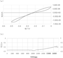
- 5 is a graph showing CV measurement (a) and discharge measurement (b) of the thermoelectric generator battery obtained in Example 1.
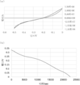
- 6 is a graph showing CV measurement (a) and discharge measurement (b) of the thermoelectric generator battery obtained in Example 2.
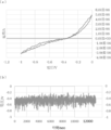
- 6 is a graph showing CV measurement (a) and discharge measurement (b) of the thermoelectric generator battery obtained in Example 3.
- 5 is a graph showing CV measurement (a) and discharge measurement (b) of the thermoelectric generator battery obtained in Example 4.
- 9 is a graph showing CV measurement (a) and discharge measurement (b) of the thermoelectric generator battery obtained in Example 5.
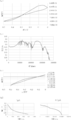
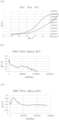
- the CV measurement at 80 ° C. (a), the discharge measurement (b), the CV measurement at 35 ° C. (c), and the discharge measurement after standing at room temperature (d) of the thermoelectric generator battery obtained in Example 6 are shown.
- 14 is a graph showing CV measurement (a) and discharge measurement (b) of the thermoelectric generator battery obtained in Example 7.
- 14 is a graph showing a CV measurement (a) of the thermoelectric generator battery obtained in Example 8 and a discharge measurement (b) after being left as it is.
- 13 is a graph showing CV measurement (a) and discharge measurement (b) of the thermoelectric generator battery obtained in Example 9.
- 14 is a graph showing a CV measurement of the thermoelectric generator battery obtained in Example 10.
- 14 is a graph showing a CV measurement (a) and a discharge measurement (b) of the thermoelectric generator battery obtained in Example 11.
- 19 is a graph showing CV measurement of the thermoelectric generator battery obtained in Example 12.
- 19 is a graph showing a CV measurement of the thermoelectric generator battery obtained in Example 13.
- thermoelectric generator battery obtained in Example 14 is a graph showing CV measurement (a) and discharge measurement (b) of the thermoelectric generator battery obtained in Example 15.
- 17 is a graph showing CV measurement (a) and discharge measurement (b) of the thermoelectric generator battery obtained in Example 16.
- 18 is a graph showing CV measurement (a) and discharge measurement (b) at 70 ° C. and discharge measurement (c) at 50 ° C. of the thermoelectric generator battery obtained in Example 17.
- the working electrode of the present invention is not particularly limited as long as it includes n-type silicon and germanium.
- Germanium is a thermoelectric conversion material that generates holes and electrons, and can generate about 10 18 / cm 3 of thermally excited electrons and holes.
- N-type silicon is an electron transporting material that transports thermally excited electrons generated by a thermoelectric conversion material.
- N-type silicon is obtained by adding a trace amount of a pentavalent element such as phosphorus to pure silicon as an impurity. Pure silicon having four valence electrons is an insulator because electrons do not move, but n-type silicon contains five valence electrons such as phosphorus, so that one extra electron can move freely. , A conductor.
- Examples of the pentavalent element include phosphorus and arsenic.
- the amount ratio of n-type silicon to germanium at the working electrode is not particularly limited as long as the effects of the present invention can be obtained, but is preferably 1000: 1 to 10: 1, and more preferably 500: 1 to 100. : 1. With the above range, n-type silicon can efficiently transport thermally excited electrons generated by germanium.
- the working electrode in the present invention can be manufactured by, for example, stacking germanium on n-type silicon. However, when germanium is directly laminated on n-type silicon, the bonding may be weak. Therefore, it is preferable to stack n-type silicon and germanium via a binder, for example. Examples of the binder include chromium, nickel, titanium, and tin.
- the amount of the binder is not particularly limited as long as the bond between n-type silicon and germanium can be strengthened. For example, 0.001 to 1 part by volume of binder is used with respect to 100 parts by volume of germanium. I just need.
- the counter electrode is not limited as long as it can transport electrons.
- the counter electrode may be provided as a counter electrode layer or may be provided in the form of a conducting wire. In the case of the counter electrode layer, it can be manufactured by a vacuum evaporation method or a spin coating method.
- the polymer may be a polymer comprising a repeating unit of the formula (1).
- the solid electrolyte may be a solid electrolyte composed of the polymer or a derivative thereof.
- the polymer is not particularly limited as long as it has a repeating unit included in the formula (1). Examples thereof include polyvinylidene fluoride, polyvinyl alcohol, polyethylene glycol, polypropylene glycol, polyethylene carbonate, and polypropylene carbonate. No.
- the two terminal groups are not particularly limited as long as the effects of the present invention can be obtained. Examples thereof include a hydrogen atom, a hydroxyl group, an alkyloxirane group having 1 to 6 carbon atoms, an acryloyl group, and a 1 to 6 carbon atoms.
- Alkyl carboxyl group alkylamino group having 1 to 6 carbon atoms, alkyl group having 1 to 6 carbon atoms, aldehyde group, alkyl aldehyde group having 1 to 6 carbon atoms, alkyl amide group having 1 to 6 carbon atoms, 1 carbon atom
- a hydrogen atom and / or a hydroxyl group preferably a hydrogen atom and / or a hydroxyl group.
- the polymer derivative may have a substituent on a side chain. That is, the hydrogen atom in the side chain may be substituted.
- the substituent is not particularly limited, but general groups such as an amino group, a carboxyl group, an alkyl group, an aryl group, a glycidyl group, a cyano group, a methylsulfonyl group, a phosphoryl group, and a nitro group can be used.
- the molecular weight of the polymer or its derivative is from 200 to 1,000,000, preferably from 400 to 100,000, more preferably from 400 to 20,000, and still more preferably from 400 to 6,000. , Most preferably from 600 to 2,000.
- the molecular weight of a polymer or its derivative shall mean the weight average molecular weight measured in terms of polystyrene by gel permeation chromatography (GPC).
- GPC device HLC-8120 (manufactured by Tosoh Corporation): Column: TSK gel Multipore HXL-M (manufactured by Tosoh Corporation, 7.8 mm ID (inner diameter) x 30.0 cm)
- Eluent tetrahydrofuran (THF)
- the solid electrolyte contains polyethylene glycol having a molecular weight of 200 to 1,000,000 or a derivative thereof (hereinafter, may be referred to as polyethylene glycol or the like).
- Polyethylene glycol (PEG) is a polymer compound obtained by polymerizing ethylene glycol, and is represented by the formula HO— (CH 2 —CH 2 —O) n-1 —CH 2 —CH 2 —OH. That is, the repeating unit of polyethylene glycol is represented by the following formula (2).
- the derivative of polyethylene glycol is not particularly limited, and examples thereof include a derivative in which one or both of the hydrogen atoms (-H) at both ends are substituted with a substituent.
- substituents examples include an alkyloxirane group having 1 to 6 carbon atoms, an acryloyl group, an alkylcarboxyl group having 1 to 6 carbon atoms, an alkylamino group having 1 to 6 carbon atoms, an alkyl group having 1 to 6 carbon atoms, and an aldehyde group.
- an alkylmaleimide group having 1 to 6 carbon atoms, a sulfonyl group, an amino group, or a thiol group is an alkylmaleimide group having 1 to 6 carbon atoms, a sulfonyl group, an amino group, or a thiol group.
- polyethylene glycol diglycidyl ether, polyethylene glycol diacrylate, H 2 N— (CH 2 —CH 2 —O) n-1 —CH 2 —CH 2 —O—CH 2 —CH 2 —COOH, H 2 N- (CH 2 —CH 2 —O) n-1 —CH 2 —CH 2 —O—CH 2 —CH 2 —NH 2 , HOOC— (CH 2 —CH 2 —O) n ⁇ 1 —CH 2 —CH 2 —O—CH 2 —CH 2 —COOH, HOOC—CH 2 —CH 2 —COO— (CH 2 —CH 2 —O) n-1 —CH 2 —CH 2 —O—CO—CH 2 — CH 2 —COOH or polyethylene glycol dimethacrylate can be mentioned.
- the derivative of polyethylene glycol may have a substituent on the side chain.
- the substituent is not particularly limited, general groups such as an amino group, a carboxyl group, an alkyl group, an aryl group, a glycidyl group, a cyano group, a methylsulfonyl group, a phosphoryl group, and a nitro group can be used.
- the solid electrolyte contains polypropylene glycol having a molecular weight of 200 to 1,000,000 or a derivative thereof (hereinafter, may be referred to as polypropylene glycol or the like).
- Polypropylene glycol (PPG) is a polymer compound obtained by polymerizing propylene glycol, and has a formula of HO— (CH 2 —CH 2 (CH 3 ) —O) n-1 —CH 2 —CH 2 (CH 3 ) —OH It is represented by That is, the repeating unit of polypropylene glycol is represented by the following formula (3).
- the derivative of polypropylene glycol is not particularly limited, and examples thereof include a derivative in which one or both of the hydrogen atoms (-H) at both ends are substituted with a substituent.
- Examples of the terminal substituent include the substituents described in the section of the polyethylene glycol, and specific derivatives are the same as those in the section of the polyethylene glycol.
- the derivative of polypropylene glycol may have a substituent on the side chain. Examples of the substituent on the side chain include the substituents described in the section of polyethylene glycol.
- the solid electrolyte contains polyethylene carbonate having a molecular weight of 200 to 1,000,000 or a derivative thereof (hereinafter, may be referred to as polyethylene carbonate or the like).
- Polyethylene carbonate (PEC) is a polymer compound obtained by polymerizing ethylene carbonate, and has a formula of HO— (CH 2 —CH 2 —O—CO—O) n-1 —CH 2 —CH 2 —O—CO—OH. It is represented by That is, the repeating unit of polyethylene carbonate is represented by the following formula (4).
- the derivative of polyethylene carbonate is not particularly limited, and examples thereof include a derivative in which one or both of the hydrogen atoms (-H) at both ends are substituted with a substituent.
- the terminal substituent include the substituents described in the section of the polyethylene glycol, and specific derivatives are the same as those in the section of the polyethylene glycol.
- the derivative of polyethylene carbonate may have a substituent on the side chain. Examples of the substituent on the side chain include the substituents described in the section of polyethylene glycol.
- the solid electrolyte contains polypyrropyrene carbonate having a molecular weight of 200 to 1,000,000 or a derivative thereof (hereinafter, may be referred to as polypyropyrene carbonate or the like).
- Polypropylene carbonate (PPC) is a polymer compound obtained by polymerizing propylene carbonate, and is HO— (CH 2 —CH 2 (CH 3 ) —O—CO—O) n-1 —CH 2 —CH 2 (CH 3 ) Represented by the formula -O-CO-OH. That is, the repeating unit of the polypyrropylene carbonate is represented by the following formula (5).
- the derivative of polypropylene carbonate is not particularly limited, and examples thereof include a derivative in which one or both of the hydrogen atoms (—H) at both ends are substituted with a substituent.
- the terminal substituent include the substituents described in the section of the polyethylene glycol, and specific derivatives are the same as those in the section of the polyethylene glycol.
- the derivative of polypropylene carbonate may have a substituent on the side chain. Examples of the substituent on the side chain include the substituents described in the section of polyethylene glycol.
- the solid electrolyte contains polyvinylidene fluoride having a molecular weight of 200 to 1,000,000 or a derivative thereof (hereinafter, may be referred to as polyvinylidene fluoride or the like).
- Polyvinylidene fluoride (PVDF) is a polymer compound obtained by polymerizing vinylidene fluoride, and is represented by a formula of HO— (CH 2 —CF 2 ) n —H. That is, the repeating unit of polyvinylidene fluoride is represented by the following formula (6).
- the derivative of polyvinylidene fluoride is not particularly limited, and examples thereof include a derivative in which one or both of hydrogen atoms (—H) at both ends are substituted with a substituent.
- the terminal substituent include the substituents described in the section of the polyethylene glycol, and specific derivatives are the same as those in the section of the polyethylene glycol.
- the derivative of polyvinylidene fluoride may have a substituent on a side chain. Examples of the substituent on the side chain include the substituents described in the section of polyethylene glycol.
- the solid electrolyte contains polyvinyl alcohol having a molecular weight of 200 to 1,000,000 or a derivative thereof (hereinafter, may be referred to as polyvinyl alcohol or the like).
- Polyvinyl alcohol (PVA) is a polymer compound obtained by polymerizing vinyl alcohol, and is represented by the formula HO— (CH 2 —CH (OH)) n —H. That is, the repeating unit of polyvinyl alcohol is represented by the following formula (7).
- the derivative of polyvinyl alcohol is not particularly limited, and examples thereof include a derivative in which one or both of the hydrogen atoms (-H) at both ends are substituted with a substituent.
- terminal substituent examples include the substituents described in the section of the polyethylene glycol, and specific derivatives are the same as those in the section of the polyethylene glycol.
- the derivative of polyvinyl alcohol may have a substituent on the side chain. Examples of the substituent on the side chain include the substituents described in the section of polyethylene glycol.
- the solid electrolyte is poly (vinylidene fluoride-co-hexafluoropropylene) having a molecular weight of 200 to 1,000,000 or a derivative thereof (hereinafter, poly (vinylidene fluoride-co-hexafluoropropylene)) or the like. ).
- Poly (vinylidene fluoride-co-hexafluoropropylene) is a polymer compound obtained by copolymerizing vinylidene fluoride and hexafluoropropylene, and is composed of HO— (CH 2 —CF 2 ) x (CF 2 —C (CF 3 ) F) It is represented by the formula of y- H. That is, the repeating unit of poly (vinylidene fluoride-co-hexafluoropropylene) is represented by the following formula (8).
- the derivative of poly (vinylidene fluoride-co-hexafluoropropylene) is not particularly limited, and examples thereof include a derivative in which one or both of the hydrogen atoms (-H) at both ends are substituted with a substituent.
- the terminal substituent include the substituents described in the section of the polyethylene glycol, and specific derivatives are the same as those in the section of the polyethylene glycol.
- the derivative of polyvinylidene fluoride may have a substituent on a side chain. Examples of the substituent on the side chain include the substituents described in the section of polyethylene glycol.
- the solid electrolyte in the present invention means a solid electrolyte that is a quasi-solid at a high temperature.
- the ion source contained in the solid electrolyte of the present invention is not particularly limited as long as it is a copper ion or an iron ion, and is monovalent copper ion, divalent copper ion, divalent iron ion, or trivalent iron ion. Is mentioned.
- the copper ion or the iron ion is preferably two stable ions having different valences. This is because one ion is oxidized or reduced to become the other ion and can carry electrons and holes. Therefore, in the case of copper ions, monovalent copper ions and divalent copper ions are preferable, and in the case of iron ions, divalent iron ions and trivalent iron ions are preferable.
- the monovalent copper ion for example, CuCl, CuBr, copper acetate (I), copper iodide (I) or copper sulfate (I) can be used.
- divalent copper ions CuCl 2 , CuTSFI 2 , copper (II) acetate, copper (II) sulfate or copper (II) acetylacetonate can be used.
- divalent iron ions Fe (C 5 H 5 ) 2 (ferrocene), K 4 [Fe (CN) 6 ], iron (II) acetylacetonate, iron (II) chloride (II) sulfate (II) or iron acetate ( II) can be used.
- trivalent iron ion FeCl 3 , K 3 [Fe (CN) 6 ], iron (III) acetylacetonate or iron (III) sulfate can be used.
- the concentration of the ion source is not particularly limited as long as the effects of the present invention can be obtained. However, it is preferable to add the ion source in an amount of, for example, 0.01 to 98 mol% based on the polymer or the like. By being in the above range, the ion source can efficiently transport electrons and holes.
- the solid electrolyte can contain other components.
- other components include, but are not limited to, polar solvents that dissolve or disperse the ion source (such as water, methanol, toluene, and tetrahydrofuran), binders (such as polyvinyl alcohol, methylcellulose, acrylic resins, and agar).
- Sintering aids magnesium oxide, yttrium oxide, calcium oxide, and the like) that assist in forming the hole transporting material can be given.
- the heat utilization battery of the present invention preferably contains an alkali metal ion as an additive.
- the alkali metal ion include a lithium ion, a sodium ion, a potassium ion, a rubidium ion, a cesium ion, and a francium ion, and a lithium ion, a sodium ion, and a potassium ion are preferable.
- the alkali metal ion is preferably, but not limited to, added to the solid electrolyte in the form of a halide.
- halogen that forms a halide with an alkali metal ion examples include fluorine, chlorine, bromine, iodine, and astatine.
- a compound of an alkali metal ion and chlorine LiCl, NaCl, KCl, RbCl, CsCl, or FrCl can be mentioned, but LiCl, NaCl, or KCl is preferable.
- the addition amount of the alkali metal halide is not particularly limited as long as the battery life can be extended.
- the heat utilization battery of the present invention can include, but is not limited to, an inorganic oxide.
- the inorganic oxide is not particularly limited as long as the effects of the present invention can be obtained, and examples thereof include titanium oxide (TiO 2 ), aluminum oxide (Al 2 O 3 ), and silicon dioxide (SiO 2 ).
- TiO 2 titanium oxide
- Al 2 O 3 aluminum oxide
- SiO 2 silicon dioxide
- the mechanism by which the heat-utilizing battery of the present invention can stably generate power and the mechanism that exhibits excellent battery life have not been analyzed in detail, but can be estimated as follows.
- the present invention is not limited by the following presumption.
- the heat utilization battery of the present invention uses a polymer having a specific repeating unit having a molecular weight of 200 to 1,000,000 or a derivative thereof as a solid electrolyte.
- the heat-utilizing power generation method enables long-term operation by controlling the balance between the oxidation-reduction reaction of ions and the diffusion of ions. That is, it is important that ions redox-reduced on the electrode surface reach redox equilibrium in the electrolyte.
- the diffusion rate of ions can be effectively controlled even at a high temperature.
- a polymer that is stable in a high temperature range is required, and it is presumed that the heat-utilizing power generation battery of the present invention can perform stable power generation.
- the discharge maintenance time of the heat utilization battery is dramatically extended by including the alkali metal ion as an additive in the heat utilization battery of the present invention. It is presumed that the alkali metal ion interacts indirectly with the redox copper ion or iron ion on the electrode surface and promotes the diffusion of the copper ion or iron ion into the solid electrolyte.
- the heat-utilizing battery of the present invention may be arranged such that the working electrode and / or the counter electrode has a metal that does not react with copper ions or iron ions, for example, titanium, gold, platinum, silver, tungsten, tantalum, stainless steel, graphene, indium, rhodium, and chromium. , Carbon, their alloys, or a combination thereof.
- the same material may be used for the working electrode and the counter electrode.
- the conductor may be provided in the form of a conductive wire, or may be provided as a layer of a conductor. In the case of a conductor layer, it can be manufactured by a vacuum evaporation method or a spin coating method.
- the heat-utilizing power generating method of the present invention includes a step of heating the heat-utilizing power generation battery to 25 ° C. or higher to generate power (heating power generation step).
- the heating temperature is not particularly limited as long as the heat-utilizing battery of the present invention can generate power. That is, germanium is not particularly limited as long as it can generate a sufficient number of thermally excited electrons and holes for power generation and the charge transporting ion pair can move in the electrolyte.
- the temperature is 35 ° C. or higher, more preferably 50 ° C. or higher, and further preferably 80 ° C. or higher.
- the upper limit of the temperature is not particularly limited as long as it is a temperature at which the charge transporting ion pair can move in and out of the electrolyte, but is, for example, 300 ° C or lower, and preferably 120 ° C or lower.
- the temperature at which the heat utilizing power generation battery of the present invention actually generates power is a temperature at which a sufficient number of thermally excited electrons and holes are generated for power generation of germanium, as well as the ease of electron transfer inherent to the material, It is determined by the ease of electron transfer at the interface with germanium in combination with the solid electrolyte, but these conditions can be examined as appropriate.
- a step of leaving the battery in an insulated state (leaving step), and further a step of heating the heat-using power generation battery to 25 ° C. or more to generate power (heating and power generation step).
- the insulating state in the leaving step means, for example, a state after a step of switching off.
- an ion source such as a copper ion or an iron ion is diffused by the solid electrolyte, thereby enabling efficient heating and power generation.
- battery life can be extended. Since the diffusion of the ion source occurs even when left for several minutes, the leaving time is not particularly limited.
- the state of diffusion of the ion source it is, for example, 1 hour or more, and preferably 2 hours or more. More preferably, it is at least 6 hours, even more preferably at least 12 hours.
- the upper limit of the leaving time is preferably within 2 days.
- the leaving step and the heating power generation step may be repeated two or more times. The number of repetitions of the leaving step and the heating and power generation step is not particularly limited.
- thermoelectric generator battery was manufactured using PEG 600 as a solid electrolyte and CuCl as an ion source.
- the working electrode was obtained by depositing 20 nm of Cr as a binder on n-Si having a thickness of about 0.5 mm, further depositing 2 ⁇ m of Ge thereon, and cutting it into 25 ⁇ 15 ⁇ 0.5 mm.
- As a counter electrode fluorine-doped tin oxide (FTO, sheet resistance 7 ⁇ / ⁇ , Aldrich) cut into a size of 25 ⁇ 15 ⁇ 2.2 mm was used.
- FTO sheet resistance 7 ⁇ / ⁇ , Aldrich
- the electrolyte was prepared by putting 0.1 g of PEG600 (Wako) in a mortar, adding CuCl (0.01 g), and stirring for 10 minutes.
- the obtained electrolyte (1 ⁇ L) was dropped on germanium of the working electrode.
- a heat-resistant insulating double-sided tape Kerpton tape having a 5 mm hole
- the germanium side of the working electrode was bonded to the FTO of the counter electrode. That is, the electrode area of the power generation unit is a circle having a diameter of 5 mm, and is 78.5 square millimeters.
- the obtained battery was set in a thermostat.
- the CV measurement was performed at a scan rate of 10 mV / sec by potential scanning.
- the discharge measurement was performed at 10 nanoamps. The results are shown in Table 1 and FIG. A power generation characteristic of an open voltage of about 0.2 V and a short circuit current of 4 microamps was observed (FIG. 1a). The discharge lasted more than 2 hours at 10 nanoamps (FIG. 1b).
- Example 2 >> In this example, the operation of Example 1 was repeated, except that acetonitrile (ACN) was used as an additive, to produce a heat-utilizing battery.
- ACN acetonitrile
- 0.1 g of PEG600 was put in a mortar, CuCl (0.01 g) was added, ACN (0.25 mL) was added as an additive, and the mixture was left at 80 ° C. for 20 minutes to evaporate ACN to prepare an electrolyte. did.
- the results are shown in Table 1 and FIG. Power generation characteristics of an open voltage of about 0.2 V and a short circuit current of about 5 microamps were observed (FIG. 2a). The discharge stabilized at about 0.2 V at 10 nanoamps and continued for about 4 hours (FIG. 2b).
- Example 3 a heat-utilizing battery was manufactured by repeating the operation of Example 2 except that PEG2000 was used instead of PEG600 as the solid electrolyte.
- PEG2000 was used instead of PEG600 as the solid electrolyte.
- 0.1 g of PEG2000 was put in a mortar, CuCl (0.01 g) was added, ACN (0.5 mL) was added as an additive, and the mixture was stirred at 80 ° C. for 10 minutes.
- the ACN was evaporated by leaving at 80 ° C. for 20 minutes to prepare an electrolyte.
- Table 1 Power generation characteristics of an open voltage of about 0.2 V and a short circuit current of 7 microamps were confirmed (FIG. 3a).
- the discharge stabilized at 10 nanoamps and lasted about 4.5 hours (FIG. 3b).
- Example 4 a heat-utilizing battery was produced by repeating the operation of Example 2 except that a mixture of PEG600 / PEDE500 was used instead of PEG600 as the solid electrolyte.
- 0.1 g of PEG600 and 0.1 g of PEDE500 were put in a mortar, CuCl (0.02 g) was added, ACN (0.5 mL) was added as an additive, and the mixture was stirred at 80 ° C. for 10 minutes.
- An electrolyte was prepared by leaving at 80 ° C. for 20 minutes and evaporating the ACN.
- Table 1 Table 1
- FIG. Generation of an open-circuit voltage of 0.2 V and a short-circuit current of 1.3 microamps was confirmed (FIG. 4a). The discharge lasted 6 hours at 10 nanoamps (FIG. 4b).
- Example 5 a heat-utilizing battery was manufactured by repeating the operation of Example 1 except that FeCl 3 was used instead of CuCl as the ion source.
- An electrolyte was prepared by placing 1 g of PEG 600 in a mortar, adding FeCl 3 (0.162 g), and dissolving FeCl 3 in PEG at 80 ° C. The results are shown in Table 1 and FIG. Power generation characteristics with an open circuit voltage of about 0.4 V and a short circuit current of about 5 microamps were observed (FIG. 5a). Discharge was stable at 10 nanoamps and was observed for about 4 hours (FIG. 5b).
- Comparative Example 1 >> In this comparative example, the operation of Example 1 was repeated, except that only Ge was used instead of n-Si and Ge as the working electrode, and Ferlocne was used instead of CuCl as the ion source.
- the working electrode was obtained by depositing 20 nm of Cr as a binder on n-Si having a thickness of about 0.5 mm, further depositing 2 ⁇ m of Ge thereon, and cutting it into 25 ⁇ 15 ⁇ 0.5 mm. Using.
- the counter electrode used was fluorine-doped tin oxide (FTO, sheet resistance 7 ⁇ / ⁇ , Aldrich) cut to a size of 25 ⁇ 15 ⁇ 2.2 mm.
- FTO fluorine-doped tin oxide
- the electrolyte was prepared by putting 0.1 g of PEG600 (Wako) in a mortar, adding Ferrocne (0.0093 g), and stirring for 10 minutes. Table 1 shows the results. Although the open circuit voltage was about 0.5 V, the short circuit current was as low as about 0.1 microampere, and the discharge maintaining time was as short as 40 minutes.
- Comparative Example 2 >> In this comparative example, except for using the SnCl 2 ⁇ H 2 O instead of CuCl as the ion source, to produce a heat utilization onset cells by repeating the procedure of Example 1.
- the electrolyte was prepared by putting 0.1 g of PEG600 (Wako) in a mortar, adding SnCl 2 .H 2 O (0.0226 g), and stirring for 10 minutes. Table 1 shows the results. There was no power generation.
- Comparative Example 2 In this comparative example, the operation of Example 1 was repeated, except that PEI500 was used instead of PEG600 as the solid electrolyte, to produce a heat-utilizing battery.
- the electrolyte was prepared by putting 0.1 g of PEI500 (Wako) in a mortar, adding CuCl (0.02 g), and stirring for 10 minutes. Table 1 shows the results. There was no power generation.
- Example 6 >> In the present embodiment, the operation of Example 1 was repeated, except that CuCl and CuCl 2 were used as the ion source instead of CuCl, and LiCl was used as an additive. Produced. The electrolyte was prepared by adding 0.1 g of PEG 600 (Wako) to a mortar, adding CuCl (0.01 g), CuCl 2 (0.014 g), and LiCl (0.005 g) as an additive, and stirring for 10 minutes. Was prepared. The results are shown in Table 1 and FIG. Power generation characteristics with an open voltage of about 0.25 V and a short circuit current of about 4 microamps were observed (FIG. 6a). Discharge was observed at 10 nanoamps for 505 hours (FIG. 6b).
- Example 7 >> In this example, the operation of Example 6 was repeated, except that PEG100000 having a molecular weight of 100,000 was used instead of PEG600 as the solid electrolyte, to produce a heat-utilizing battery.
- PEG100000 having a molecular weight of 100,000 was used instead of PEG600 as the solid electrolyte, to produce a heat-utilizing battery.
- 0.5 g of PEG100000 was put in a mortar, CuCl (0.05 g), CuCl 2 (0.07 g), and LiCl (0.1 g) as an additive were added, and the mixture was stirred at room temperature for 10 minutes.
- the electrolyte was prepared by vacuum drying at 60 for 2 hours.
- FIG. FIG. 15 shows the CV measurement at 80 ° C. Generation of an open-circuit voltage of 0.35 V and a short-circuit current of 8 microamps was confirmed (FIG. 7a). The discharge was stable at 10 nanoamps for 70 hours (FIG. 7b).
- Embodiment 8 >> In this example, the operation of Example 6 was repeated, except that acetonitrile was further used as an additive, to produce a heat-utilizing battery.
- acetonitrile was further used as an additive, to produce a heat-utilizing battery.
- 0.1 g of PEG600 (Wako) was placed in a mortar, and CuCl (0.01 g), CuCl 2 (0.014 g), and LiCl (0.005 g) and ACN (0.5 mL) were added as additives. By stirring for 10 minutes.
- FIG. 8a shows the CV measurement at 80 ° C. Power generation characteristics of an open voltage of about 0.35 V and a short circuit current of about 6 microamps were observed (FIG. 8A).
- the battery was maintained at 80 ° C., and the discharge characteristics at 100 nanoamperes were confirmed. As a result, a voltage of about 0.4 V was shown on average, and the discharge was completed in about 80 hours. However, when the battery was allowed to stand at 80 ° C. for one day, it was confirmed again that an open circuit voltage of 0.5 V and a short-circuit current of 2 ⁇ A were generated. This discharge lasted about one day. When the battery was further left at 80 ° C. for 2 days, the discharge characteristics with an open voltage of 0.5 V were recovered (FIG. 8B), and the discharge continued for about 2 days.
- Example 9 a heat-utilizing battery was produced by repeating the operation of Example 6 except that KCl was used instead of LiCl as an additive.
- KCl was used instead of LiCl as an additive.
- 0.1 g of PEG 600 was placed in a mortar, CuCl (0.01 g), CuCl 2 (0.014 g), KCl (0.034 g) as an additive, ACN (0.25 mL), and ethanol (0.25 mL). ) was added and the mixture was stirred at room temperature for 10 minutes.
- the electrolyte was prepared by vacuum drying at 60 for 4 hours. The results are shown in Table 1 and FIG. Generation of an open-circuit voltage of 0.25 V and a short-circuit current of about 10 microamps was confirmed (FIG. 9a). The discharge lasted 120 hours at 10 nanoamps (FIG. 9b).
- Example 10 As the solid electrolyte PVDF1000000, to prepare a thermoelectric generation batteries using CuCl, the CuCl 2 as the ion source.
- the working electrode used was one in which 20 nm of Cr was deposited as a binder on n-Si having a thickness of about 0.5 mm, Ge was deposited thereon at 2 ⁇ m, and the disk was cut into a 1 cm diameter disk.
- the counter electrode used was a 1 cm diameter, 0.5 mm thick SUS disk coded using PEDOT / PSS.
- a mortar was filled with PVDF (0.1 g), CuCl (0.02 g), and LiCl (0.03 g).
- Example 11 As the solid electrolyte PPC40000, to prepare a thermoelectric generation batteries using CuCl, the CuCl 2 as the ion source.
- the working electrode used was one in which 20 nm of Cr was deposited as a binder on n-Si having a thickness of about 0.5 mm, Ge was deposited thereon at 2 ⁇ m, and the disk was cut into a 1 cm diameter disk.
- the counter electrode used was a 1 cm diameter, 0.5 mm thick SUS disk coded using PEDOT / PSS.
- a mortar was filled with PPC (0.1 g), CuCl (0.02 g), and LiCl (0.03 g).
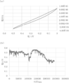
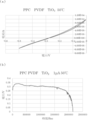
- test cells were assembled in 2035 button cell hardware in a glove box. The obtained battery was set in a thermostat. The CV measurement was performed at a scan rate of 10 mV / sec by potential scanning. At 80 ° C., power generation characteristics of an open voltage of about 0.15 V and a short circuit current of 120 ⁇ A were observed. The discharge lasted for more than 14 hours at 1 ⁇ A (FIG. 11, Table 2).
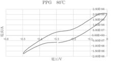
- Example 12 As the solid electrolyte PPG2000, to prepare a thermoelectric generation batteries using CuCl, the CuCl 2 as the ion source.
- the working electrode used was one in which 20 nm of Cr was deposited as a binder on n-Si having a thickness of about 0.5 mm, Ge was deposited thereon at 2 ⁇ m, and the disk was cut into a 1 cm diameter disk.
- the counter electrode used was a 1 cm diameter, 0.5 mm thick SUS disk coded using PEDOT / PSS.
- As the electrolyte a mortar was filled with PPG (0.1 g), CuCl (0.02 g), and LiCl (0.03 g).
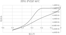
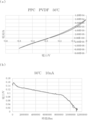
- Example 13 As the solid electrolyte PPG2000 / PVDF1000000, to prepare a thermoelectric generation batteries using CuCl, the CuCl 2 as the ion source.
- the working electrode used was one in which 20 nm of Cr was deposited as a binder on n-Si having a thickness of about 0.5 mm, Ge was deposited thereon at 2 ⁇ m, and the disk was cut into a 1 cm diameter disk.
- the counter electrode used was a 1 cm diameter, 0.5 mm thick SUS disk coded using PEDOT / PSS.
- a mortar was charged with PPG (0.05 g), PVDF (0.05 g), CuCl (0.02 g), and LiCl (0.03 g).
- Example 14 As the solid electrolyte PEG100000 / PVDF1000000, to prepare a thermoelectric generation batteries using CuCl, the CuCl 2 as the ion source.
- the working electrode used was one in which 20 nm of Cr was deposited as a binder on n-Si having a thickness of about 0.5 mm, Ge was deposited thereon at 2 ⁇ m, and the disk was cut into a 1 cm diameter disk.
- the counter electrode used was a 1 cm diameter, 0.5 mm thick SUS disk coded using PEDOT / PSS.
- PEG (0.05 g), PVDF (0.05 g), CuCl (0.02 g), and LiCl (0.03 g) were put in a mortar.
- thermoelectric generator battery was manufactured using PPC 40000 / PVDF100000 as a solid electrolyte and CuCl and CuCl 2 as an ion source.
- the working electrode used was one in which 20 nm of Cr was deposited as a binder on n-Si having a thickness of about 0.5 mm, Ge was deposited thereon at 2 ⁇ m, and the disk was cut into a 1 cm diameter disk.
- the counter electrode used was a 1 cm diameter, 0.5 mm thick SUS disk coded using PEDOT / PSS.
- PPC 0.05 g
- PVDF 0.05 g
- CuCl 0.02 g
- LiCl (0.03 g
- Test cells were assembled in 2035 button cell hardware in a glove box. The obtained battery was set in a thermostat. The CV measurement was performed at a scan rate of 10 mV / sec by potential scanning. At 50 ° C., power generation characteristics of an open voltage of about 0.28 V and a short circuit current of 100 ⁇ A were observed. The discharge continued for 3119 hours or more at 10 nA (FIG. 15, Table 2).
- Example 16 As the solid electrolyte PPC40000 / PVDF1000000, to prepare a thermoelectric generation batteries using CuCl, the CuCl 2 as the ion source.
- the working electrode used was one in which 20 nm of Cr was deposited as a binder on n-Si having a thickness of about 0.5 mm, Ge was deposited thereon at 2 ⁇ m, and the disk was cut into a 1 cm diameter disk.
- the counter electrode used was a 1 cm diameter, 0.5 mm thick SUS disk coded using PEDOT / PSS.
- a mortar was filled with PPC (0.05 g), PVDF (0.05 g), CuCl (0.02 g), and LiCl (0.03 g).
- test cells were assembled in 2035 button cell hardware in a glove box. The obtained battery was set in a thermostat. The CV measurement was performed at a scan rate of 10 mV / sec by potential scanning. At 50 ° C., power generation characteristics of an open voltage of about 0.28 V and a short circuit current of 100 ⁇ A were observed. The discharge lasted 595 hours or more at 1 ⁇ A (FIG. 16, Table 2).
- thermoelectric generator battery was manufactured using PEC250,000 / PVA5000 as a solid electrolyte and CuCl and CuCl 2 as an ion source.
- the working electrode used was one in which 20 nm of Cr was deposited as a binder on n-Si having a thickness of about 0.5 mm, Ge was deposited thereon at 2 ⁇ m, and the disk was cut into a 1 cm diameter disk.
- a SUS disk having a diameter of 1 cm and a thickness of 0.5 mm coded using PEDOT / PSS was used.
- the heat-using power generation battery and the heat-using power generation method using the same according to the present invention include a small portable power generation device, a geothermal power generation, a thermoelectric power generation using exhaust heat of an automobile, and a substation, a steel furnace, a factory, or a garbage incineration plant. It can be used for power generation using heat utilizing waste heat (exhaust heat).
Landscapes
- Chemical & Material Sciences (AREA)
- Chemical Kinetics & Catalysis (AREA)
- Secondary Cells (AREA)
- Battery Electrode And Active Subsutance (AREA)
- Hybrid Cells (AREA)
Abstract
Priority Applications (3)
| Application Number | Priority Date | Filing Date | Title |
|---|---|---|---|
| JP2020535775A JP7329517B2 (ja) | 2018-08-06 | 2019-08-06 | 熱利用発電池、及びそれを用いた熱利用発電方法 |
| US17/266,422 US11758814B2 (en) | 2018-08-06 | 2019-08-06 | Heat-utilizing power generation battery and heat-utilizing power generation method using same |
| CN201980052357.5A CN112689907B (zh) | 2018-08-06 | 2019-08-06 | 热利用发电电池及使用该热利用发电电池的热利用发电法 |
Applications Claiming Priority (2)
| Application Number | Priority Date | Filing Date | Title |
|---|---|---|---|
| JP2018-147465 | 2018-08-06 | ||
| JP2018147465 | 2018-08-06 |
Publications (1)
| Publication Number | Publication Date |
|---|---|
| WO2020031992A1 true WO2020031992A1 (fr) | 2020-02-13 |
Family
ID=69414901
Family Applications (1)
| Application Number | Title | Priority Date | Filing Date |
|---|---|---|---|
| PCT/JP2019/030800 Ceased WO2020031992A1 (fr) | 2018-08-06 | 2019-08-06 | Batterie de génération d'énergie utilisant de la chaleur et procédé de génération d'énergie utilisant de la chaleur l'utilisant |
Country Status (5)
| Country | Link |
|---|---|
| US (1) | US11758814B2 (fr) |
| JP (1) | JP7329517B2 (fr) |
| CN (1) | CN112689907B (fr) |
| TW (1) | TWI803679B (fr) |
| WO (1) | WO2020031992A1 (fr) |
Cited By (2)
| Publication number | Priority date | Publication date | Assignee | Title |
|---|---|---|---|---|
| WO2022128129A1 (fr) * | 2020-12-18 | 2022-06-23 | Politecnico Di Milano | Générateur d'énergie électrique contenant un matériau organique actif |
| JPWO2022191101A1 (fr) * | 2021-03-08 | 2022-09-15 |
Citations (5)
| Publication number | Priority date | Publication date | Assignee | Title |
|---|---|---|---|---|
| JPS5193193A (en) * | 1975-02-12 | 1976-08-16 | Netsukidenryokusoshi | |
| JPH04190572A (ja) * | 1990-11-26 | 1992-07-08 | Nippon Telegr & Teleph Corp <Ntt> | 温度差電池 |
| WO2001071821A1 (fr) * | 2000-03-24 | 2001-09-27 | Shin-Etsu Chemical Co., Ltd. | Generateur thermoelectrique |
| WO2012140856A1 (fr) * | 2011-04-12 | 2012-10-18 | 国立大学法人 筑波大学 | Procédé de conversion thermoélectrique et élément de conversion thermoélectrique dans lequel est utilisée la réaction d'oxydoréduction |
| WO2017038988A1 (fr) * | 2015-09-04 | 2017-03-09 | 国立大学法人東京工業大学 | Élément de génération d'énergie thermoélectrique, module de génération d'énergie thermoélectrique le comprenant et procédé de génération d'énergie thermoélectrique l'utilisant |
Family Cites Families (8)
| Publication number | Priority date | Publication date | Assignee | Title |
|---|---|---|---|---|
| JP2003219669A (ja) | 2002-01-21 | 2003-07-31 | Lsi Cooler Co Ltd | 発電素子による発電装置 |
| JP4715157B2 (ja) * | 2004-10-18 | 2011-07-06 | 株式会社豊田中央研究所 | 熱電素子 |
| JP5345832B2 (ja) | 2008-12-18 | 2013-11-20 | 新日鐵住金株式会社 | 排熱利用発電装置 |
| KR101120723B1 (ko) * | 2009-02-27 | 2012-03-23 | 성균관대학교산학협력단 | 열분자 전지 및 이의 제조 방법 |
| WO2011100438A2 (fr) * | 2010-02-10 | 2011-08-18 | Arizona Board Of Regents On Behalf Of The University Of Arizona | Dispositif thermoélectrique moléculaire |
| WO2011149991A1 (fr) * | 2010-05-24 | 2011-12-01 | The Regents Of The University Of California | Hétérostructures nanostructure inorganique-polymère organique utiles pour des dispositifs thermoélectriques |
| US20130276851A1 (en) * | 2012-04-20 | 2013-10-24 | Acreo Swedish Ict Ab | Thermoelectric device |
| JP6271311B2 (ja) * | 2014-03-24 | 2018-01-31 | 株式会社東芝 | 電気化学反応装置 |
-
2019
- 2019-08-05 TW TW108127733A patent/TWI803679B/zh active
- 2019-08-06 WO PCT/JP2019/030800 patent/WO2020031992A1/fr not_active Ceased
- 2019-08-06 JP JP2020535775A patent/JP7329517B2/ja active Active
- 2019-08-06 CN CN201980052357.5A patent/CN112689907B/zh active Active
- 2019-08-06 US US17/266,422 patent/US11758814B2/en active Active
Patent Citations (5)
| Publication number | Priority date | Publication date | Assignee | Title |
|---|---|---|---|---|
| JPS5193193A (en) * | 1975-02-12 | 1976-08-16 | Netsukidenryokusoshi | |
| JPH04190572A (ja) * | 1990-11-26 | 1992-07-08 | Nippon Telegr & Teleph Corp <Ntt> | 温度差電池 |
| WO2001071821A1 (fr) * | 2000-03-24 | 2001-09-27 | Shin-Etsu Chemical Co., Ltd. | Generateur thermoelectrique |
| WO2012140856A1 (fr) * | 2011-04-12 | 2012-10-18 | 国立大学法人 筑波大学 | Procédé de conversion thermoélectrique et élément de conversion thermoélectrique dans lequel est utilisée la réaction d'oxydoréduction |
| WO2017038988A1 (fr) * | 2015-09-04 | 2017-03-09 | 国立大学法人東京工業大学 | Élément de génération d'énergie thermoélectrique, module de génération d'énergie thermoélectrique le comprenant et procédé de génération d'énergie thermoélectrique l'utilisant |
Cited By (4)
| Publication number | Priority date | Publication date | Assignee | Title |
|---|---|---|---|---|
| WO2022128129A1 (fr) * | 2020-12-18 | 2022-06-23 | Politecnico Di Milano | Générateur d'énergie électrique contenant un matériau organique actif |
| US12484445B2 (en) | 2020-12-18 | 2025-11-25 | Termo-Ind Sa | Electric power generator containing an active organic material |
| JPWO2022191101A1 (fr) * | 2021-03-08 | 2022-09-15 | ||
| WO2022191101A1 (fr) * | 2021-03-08 | 2022-09-15 | 国立大学法人東京工業大学 | Élément de production d'énergie thermoélectrique, batterie de production d'énergie thermoélectrique et procédé de stabilisation de production d'énergie |
Also Published As
| Publication number | Publication date |
|---|---|
| CN112689907B (zh) | 2025-03-18 |
| JPWO2020031992A1 (ja) | 2021-08-12 |
| CN112689907A (zh) | 2021-04-20 |
| TWI803679B (zh) | 2023-06-01 |
| US11758814B2 (en) | 2023-09-12 |
| TW202027306A (zh) | 2020-07-16 |
| JP7329517B2 (ja) | 2023-08-18 |
| US20210296552A1 (en) | 2021-09-23 |
Similar Documents
| Publication | Publication Date | Title |
|---|---|---|
| Zhang et al. | Halide perovskite materials for energy storage applications | |
| Salama et al. | Metal–sulfur batteries: overview and research methods | |
| JP6803076B2 (ja) | 熱電発電素子及びそれを含む熱電発電モジュール、並びにそれを用いた熱電発電方法 | |
| Kakibe et al. | Binary ionic liquid electrolytes containing organo-magnesium complex for rechargeable magnesium batteries | |
| Park et al. | Low-temperature solution-processed Li-doped SnO2 as an effective electron transporting layer for high-performance flexible and wearable perovskite solar cells | |
| Li et al. | High performance liquid metal battery with environmentally friendly antimony–tin positive electrode | |
| Kin et al. | Efficient area matched converter aided solar charging of lithium ion batteries using high voltage perovskite solar cells | |
| FI128461B (en) | Rechargeable sodium cells for high energy density battery use | |
| JP6458061B2 (ja) | 太陽電池 | |
| Cui et al. | Improved performance using a plasticized polymer electrolyte for quasi-solid state dye-sensitized solar cells | |
| CN102947896A (zh) | 透明导电膜及其制造方法、染料敏化太阳能电池和固体电解质电池 | |
| JP7526483B2 (ja) | 熱電池 | |
| JP2022075784A (ja) | 太陽電池及び太陽電池の製造方法 | |
| WO2018079325A1 (fr) | Cellule thermo-électrochimique | |
| JPWO2018056295A1 (ja) | 太陽電池 | |
| JP7098166B2 (ja) | 有機無機ハイブリッド材料ならびにこれを用いたペロブスカイト型太陽電池 | |
| JP7329517B2 (ja) | 熱利用発電池、及びそれを用いた熱利用発電方法 | |
| Senthil et al. | High performance dye-sensitized solar cell based on 2-mercaptobenzimidazole doped poly (vinylidinefluoride-co-hexafluoropropylene) based polymer electrolyte | |
| JP7671752B2 (ja) | 太陽電池 | |
| US8974974B1 (en) | Class of solid-state electrolytes for rechargeable lithium batteries | |
| Ida et al. | Investigation on the effect of nitrogenous compound benzotriazole on the structural, thermal and dielectric properties of PEO-PMMA blended polymer electrolyte system and its performance in dye sensitized solar cells | |
| JP6725221B2 (ja) | 薄膜太陽電池 | |
| JPWO2020031992A5 (fr) | ||
| US20240164215A1 (en) | Thermoelectric power generating element, thermoelectric power generating battery, and power generation stabilizing method | |
| Pullanjiyot et al. | Synthesis and electrochemical characterization of physically cross-linked gel electrolyte for QSDSSC application |
Legal Events
| Date | Code | Title | Description |
|---|---|---|---|
| 121 | Ep: the epo has been informed by wipo that ep was designated in this application |
Ref document number: 19847219 Country of ref document: EP Kind code of ref document: A1 |
|
| ENP | Entry into the national phase |
Ref document number: 2020535775 Country of ref document: JP Kind code of ref document: A |
|
| NENP | Non-entry into the national phase |
Ref country code: DE |
|
| 122 | Ep: pct application non-entry in european phase |
Ref document number: 19847219 Country of ref document: EP Kind code of ref document: A1 |
|
| WWG | Wipo information: grant in national office |
Ref document number: 201980052357.5 Country of ref document: CN |