WO2012140910A1 - Dispositif de traçage de courbe, procédé de traçage de courbe, programme de traçage de courbe et circuit intégré - Google Patents
Dispositif de traçage de courbe, procédé de traçage de courbe, programme de traçage de courbe et circuit intégré Download PDFInfo
- Publication number
- WO2012140910A1 WO2012140910A1 PCT/JP2012/002590 JP2012002590W WO2012140910A1 WO 2012140910 A1 WO2012140910 A1 WO 2012140910A1 JP 2012002590 W JP2012002590 W JP 2012002590W WO 2012140910 A1 WO2012140910 A1 WO 2012140910A1
- Authority
- WO
- WIPO (PCT)
- Prior art keywords
- points
- point
- curve
- division
- line
- Prior art date
- Legal status (The legal status is an assumption and is not a legal conclusion. Google has not performed a legal analysis and makes no representation as to the accuracy of the status listed.)
- Ceased
Links
Images





Classifications
-
- G—PHYSICS
- G06—COMPUTING OR CALCULATING; COUNTING
- G06T—IMAGE DATA PROCESSING OR GENERATION, IN GENERAL
- G06T11/00—Two-dimensional [2D] image generation
- G06T11/20—Drawing from basic elements
- G06T11/23—Drawing from basic elements using straight lines or curves
-
- G—PHYSICS
- G06—COMPUTING OR CALCULATING; COUNTING
- G06F—ELECTRIC DIGITAL DATA PROCESSING
- G06F17/00—Digital computing or data processing equipment or methods, specially adapted for specific functions
- G06F17/10—Complex mathematical operations
- G06F17/17—Function evaluation by approximation methods, e.g. inter- or extrapolation, smoothing, least mean square method
-
- G—PHYSICS
- G09—EDUCATION; CRYPTOGRAPHY; DISPLAY; ADVERTISING; SEALS
- G09G—ARRANGEMENTS OR CIRCUITS FOR CONTROL OF INDICATING DEVICES USING STATIC MEANS TO PRESENT VARIABLE INFORMATION
- G09G5/00—Control arrangements or circuits for visual indicators common to cathode-ray tube indicators and other visual indicators
- G09G5/22—Control arrangements or circuits for visual indicators common to cathode-ray tube indicators and other visual indicators characterised by the display of characters or indicia using display control signals derived from coded signals representing the characters or indicia, e.g. with a character-code memory
- G09G5/24—Generation of individual character patterns
- G09G5/28—Generation of individual character patterns for enhancement of character form, e.g. smoothing
Definitions
- the present invention relates to a curve drawing technique for approximating a curve portion of a contour line such as a character or a figure with a plurality of line segments.
- drawing a curved portion of a character such as a font or a graphic includes a process of approximating the curved portion of the outline with a plurality of line segments and filling the inside of the outline represented by the line segment.
- Graphics technology is used.
- the quality of characters and figures approximated by this technique depends on the smoothness of the connecting portion (hereinafter referred to as an edge) between the line segments used for the approximation. Therefore, as a result of performing the approximation process as a result, if the edge is not smooth enough, further approximation is performed using a line segment so that the edge is swollen.
- Patent Document 1 discloses a technique for determining whether or not further approximation is necessary depending on whether or not the angle formed by two line segments constituting an edge satisfies a predetermined condition derived from an empirical rule. Is disclosed.
- an object of the present invention is to provide a curve drawing apparatus that determines whether further approximation is necessary or not by a simple method with a lower calculation load than in the past.
- the present invention is a curve drawing apparatus that linearly approximates a contour line of a curve having a width, which is defined by a center line and a line width, on the center line that divides the center line
- Dividing point calculation means for calculating a plurality of dividing points, and for each of the dividing points, a dividing point calculation for calculating two separating points that are equidistant from the dividing point along the normal line of the center line passing through the dividing points.
- the separation points of each set when the separation points on the same side with respect to the straight line passing through the two division points are paired
- the curve drawing apparatus of the present invention has the above-described configuration, and compares two distances between the separation points to determine whether the longer one of the partial contours is approximated by more line segments than the shorter one. This can be determined by a simple method with a lower calculation load than before.
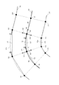
- the figure which represented typically a part of curve which should be drawn based on one embodiment of this invention The block diagram which shows the structure of the curve drawing apparatus which concerns on one embodiment of this invention The figure which expanded further a part of curve of FIG. 1 based on one embodiment of this invention.
- generated by the curve formation part based on one embodiment of this invention The flowchart which shows the approximation process based on one embodiment of this invention
- finish of a basic approximate calculation in the case of n 0 based on one embodiment of this invention.
- a curve drawing apparatus is an apparatus that draws a curve having a width by approximating a contour line of the curve with a plurality of line segments.
- the information given to the curve drawing device regarding the curve to be drawn is (a) path information representing the path that is the center line of the curve to be drawn, and (b) line width information representing the line width of the curve to be drawn. is there.
- FIG. 1 is a diagram schematically showing a part of a curve to be drawn.
- contour lines 102 and 103 indicate the contour lines of the curve to be drawn
- path 101 indicates the path that is the center line of the curve to be drawn.
- the contour line 102 and the path are separated by half the line width (hereinafter referred to as half width) of the curve to be drawn, and the contour line 103 and the path are separated by half width.
- the curve drawing apparatus When performing the approximation process, the curve drawing apparatus first generates divided paths (D1 to D7 in the figure) by dividing the path into a predetermined length. The curve drawing apparatus performs an approximation process in units of this divided path. Next, the curve drawing apparatus calculates the normal lines (normal lines N1 to N8) of the paths at the end points (divided points P1 to P8) of the divided path. These normals delimit contour lines as shown in the figure. Hereinafter, each portion of the contour line delimited by the normal line is referred to as a “partial contour line” (O11 to O17, O21 to O27 in the figure).
- partial contour lines two of the partial contour lines that are divided by the normal line passing through the two end points of the certain divided path (hereinafter referred to as “partial contour lines corresponding to the divided path”) are divided into two.
- partial contour lines corresponding to the divided path D5, O15 and O25.
- the longer one is called “long side” and the shorter one is called “short side”.
- the curve drawing apparatus approximates a curve using a plurality of line segments for a longer one of the partial outlines corresponding to the division pass (hereinafter referred to as “long partial outline”), or creates a partial outline.
- a determination is made as to whether or not to approximate one line segment connecting the end points of the line (hereinafter also referred to as “approximation determination”).
- the curve drawing apparatus performs this approximation determination by simple calculation of whether or not the ratio ( ⁇ ) of the lengths of the long side and the short side corresponding to the divided path is larger than a predetermined value (for example, 2).
- the curve drawing apparatus always approximates the shorter one of the partial contour lines corresponding to the divided path (hereinafter referred to as “short partial contour line”) with one line segment,
- short partial contour line the partial contour lines corresponding to the divided path
- each divided path is a smooth curve when the approximate curve approximated by one line segment is displayed on the display device for the short partial contour corresponding to the divided path. Is divided into lengths that are visible.
- ⁇ in FIG. 1 represents the ratio of the length of the long side to the short side for each of the divided paths.
- the ratio ⁇ of the long side (L11) and the short side (L21) corresponding to the divided path D1 is 1.2. Therefore, the curve drawing apparatus determines that ⁇ is 2 or less, and approximates the longer partial contour line O11 of the partial contour lines O11 and O21 corresponding to the divided path D1 to L11 which is one line segment. To do.
- ⁇ is 2 or less, so the curve drawing apparatus approximates the long partial outline corresponding to each divided path with one line segment.
- the curve drawing apparatus determines that the ratio ⁇ of the lengths of the long side (L14) and the short side (L24) is 3, which is larger than 2. Therefore, the curve drawing apparatus approximates O14, which is the longer one of the partial contour lines O14 and O24 corresponding to the division path D4, with an approximate line A14 formed by connecting a plurality of line segments. Also for the divided path D5, the curve drawing apparatus determines that the ratio ⁇ of the length of the long side (L15) to the short side (L25) is 3.2 and is larger than the predetermined value 2.
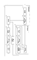
- FIG. 2 is a block diagram showing a configuration of the curve drawing apparatus 1 according to an embodiment of the present invention.
- the curve drawing device 1 includes a path dividing unit 10, a tangent vector calculating unit 11, a contour point calculating unit 12, a determining unit 13, a contour approximate line generating unit 14, a division coefficient determining unit 15, a curve forming unit 16, and a drawing unit 17. Consists of including.
- the path dividing unit 10 acquires, as inputs, path information representing a path that is a center line of a curve to be drawn and line width information representing a line width of the curve to be drawn.
- the path information is represented by a coordinate sequence of end points and control points of a cubic Bezier curve.
- the path dividing unit 10 When acquiring the path information, the path dividing unit 10 generates a divided path by dividing the path into a predetermined length. At this time, the path dividing unit 10 holds division points that divide the path into predetermined lengths.
- division points, straight lines, points on the curve, and other points are expressed in a coordinate format such as (x coordinate, y coordinate). It may be expressed in the form of Hereinafter, “calculating the coordinates of a point on the coordinate axis” is expressed as “calculating a point” for convenience.
- the tangent vector calculation unit 11 calculates a tangent (represented by a tangent vector) and a normal (represented by a normal vector) for the path at each division point calculated by the path division unit 10.
- the contour point calculation unit 12 calculates a contour point corresponding to each division point.
- the contour point is a point separated from the dividing point by a half width along the normal vector of the path at the dividing point. That is, there are two contour points corresponding to one division point.
- FIG. 3 is a diagram schematically showing a part of a curve to be drawn (hereinafter referred to as a partial curve), and is an enlarged part of FIG.
- symbol is attached
- the contours of the partial curves are the contour line 102 and the contour line 103.
- a path 101 indicates a partial curve path.
- the division points P4 to P7 indicate the division points that divide the path 101.
- the division path D4 indicates a division path in which the path 101 is divided by division points P4 and P5.
- the division path D5 and the division path D6 indicate a division path in which the path 101 is divided by division points P5 and P6, and a division path in which the path 101 is divided by division points P6 and P7, respectively.
- the segments 131 to 133 are line segments connecting adjacent division points P4 and P5, line segments connecting division points P5 and P6, and line segments connecting division points P6 and P7. .
- a line segment connecting two division points is referred to as a “segment”.
- the tangent vector 141 indicates a tangent vector at the dividing point P5 for the path 101.
- the tangent vector 142 indicates a tangent vector at the dividing point P6 for the path 101.
- the direction of the tangent vector at each division point is defined to match the direction from the start point to the end point of the path.
- the start point is a dividing point P4 and the end point is a dividing point P7.
- the tangent vector at each division point is a unit vector having a size of 1.
- Normal vectors 151 and 152 indicate normal vectors at the dividing point P5 for the path 101.
- the normal vectors 153 and 154 indicate normal vectors at the dividing point P6 for the path 101.
- the normal vector at each division point is a unit vector having a size of one.
- the contour point 162 and the contour point 172 are contour points that are separated from each other by half width in the two directions of the normal vector 151 and the normal vector 152 along the normal line from the dividing point P5.
- the “contour point separated from the division point by a half width along the normal” is hereinafter referred to as “contour point corresponding to the division point”.
- the contour points corresponding to the dividing point P4 are the contour point 161 and the contour point 171
- the contour points corresponding to the dividing point P6 are the contour point 163 and the contour point 173.
- Contour points corresponding to the point P7 are a contour point 164 and a contour point 174.
- Each contour point is a point on one of the contour line 102 and the contour line 103.
- the determination unit 13 determines whether the contour point calculated by the contour point calculation unit 12 is approximated between two adjacent contour points by the first linear approximation method or the second linear approximation method. This determination is made for each divided path. Specifically, the determination unit 13 first selects two division points that are end points of the division path (for example, division points P5 and P6 in FIG. 3). Next, the determination unit 13 is on the same side of the four contour points (contour points 162, 172, 163, and 173 as examples) corresponding to the two selected division points with respect to a straight line passing through the two division points. Distance between the contour points of each set (corresponding to the length of L15 and L25). ) Respectively.
- the line segment connecting the longer contour points of the two calculated distances is the aforementioned long side (L15 as an example), and the line segment connecting the shorter contour points is the aforementioned short side ( An example is L25).
- the determination unit 13 determines whether or not the ratio of the calculated two distances, that is, the ratio of the length of the long side to the short side is greater than a predetermined value.
- the predetermined value is 2 as an example.
- the calculated ratio is a ratio of the long side to the short side, and is always 1 or more.
- the second straight line approximation method is used, assuming that further linear approximation is necessary, and when it is determined that the calculated ratio is equal to or less than the predetermined value, It is determined that a further straight line approximation is unnecessary and the first straight line approximation method is used.
- the first straight line approximation method is a method of connecting two adjacent contour points with one line segment. As described above, the long partial contour is approximated by either the first linear approximation method or the second linear approximation method, but the short partial contour is always determined by the first linear approximation method. Approximate.
- the contour approximation line generation unit 14 approximates the long partial contour line by the first linear approximation method when the determination unit 13 determines that the ratio of the length of the long side to the short side is equal to or less than a predetermined value. .
- the contour approximation connecting the contour point 162 and the contour point 163 between the contour point 162 and the contour point 163 is performed. It is approximated by a line L15.
- the curve forming unit 16 When the determination unit 13 determines that the ratio of the length of the long side to the short side is greater than a predetermined value, the curve forming unit 16 performs an approximation operation on the long partial contour line.
- the contour approximated line generation unit 14 approximates the long partial contour line with a plurality of line segments using the result of calculation by the curve forming unit 16.
- the division coefficient determination unit 15 determines how many line segments the long partial outline is approximated when the determination unit 13 determines that the ratio of the length of the long side to the short side is greater than a predetermined value.
- a division coefficient d which is a coefficient is determined.
- the long partial outline is approximated by 2 (d + 1) line segments.
- the division coefficient d is calculated by the following equation as an example.
- floor (x) represents the maximum integer that is less than or equal to the real number x.
- the curve forming unit 16 approximates the long partial outline by the second linear approximation method when the determination unit 13 determines that the ratio of the length of the long side to the short side is greater than a predetermined value.
- the curve forming unit 16 includes a sub-contour point calculation unit 20, a tangent vector calculation unit 21, an intersection calculation unit 22, and an intersection vector calculation unit 23.
- the description of each configuration of the curve forming unit 16 will be made while explaining the second linear approximation method supplementarily using FIG. 4 for convenience of explanation.
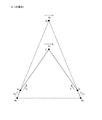
- FIG. 4 is a diagram illustrating the approximate curve generated by the curve forming unit.
- the points a 0 and b 0 in FIG. 4 indicate the end points of the long partial outline that is the target of the approximation process.
- the points a 0 and b 0 correspond to the contour points 162 and 163 in FIG. 3
- the line segment connecting the points a 0 and b 0 corresponds to L15, which is the long side to be approximated. To do
- the sub-contour point calculation unit 20 calculates sub-contour points a n and b n using the following equations 2 and 3.
- the sub-contour points a n and b n are points that are end points of line segments when the contour points a 0 and b 0 are approximated by a plurality of line segments.
- a n a n-1 +2 n-1-d (c n-1 -a n-1 ) (Formula 2)
- b n b n-1 +2 n-1-d (c n-1 -b n-1 ) (Formula 3)
- n 0, the contour points a 0 and b 0 are given as the initial values as described above, and the calculation using the equations 2 and 3 is not performed.
- the intersection c n (or c n-1 ) will be described later.
- (B) tangent vector s n, calculated tangent vector calculation unit 21 of t n is, using equations 4 and 5 below, the sub-contour points tangent vector at a n s n, and the tangent vector t at sub contour point b n Calculate n .
- the tangent vectors s n and t n are used to calculate an intersection c n described later.
- s n 2 ⁇ d ⁇ (2 d ⁇ (n ⁇ 1) ⁇ 1) u n ⁇ 1 + s n ⁇ 1 ) ⁇ (Formula 4)
- t n 2 ⁇ d ⁇ (2 d ⁇ (n ⁇ 1) ⁇ 1) ( ⁇ u n ⁇ 1 ) + t n ⁇ 1 ) ⁇ (Formula 5)
- the vector ( ⁇ u n ⁇ 1 ) in Expression 5 indicates a vector whose direction is reversed with respect to an intersection vector u n ⁇ 1 described later.
- tangent vector for t n is used referred to as "tangent vector” but does not have a significance as a tangent in the secondary contour point a n, b n. However, since it is calculated from a recurrence formula with tangent vectors s 0 and t 0 as initial values, the term “tangent vector” is used for convenience.
- intersection calculation unit 22 of intersection c n calculates a straight line extending tangent vector s n direction a n as a base point, an intersection point c n of a straight line extending tangent vector t n direction b n as a base point .
- intersection vector u n calculated intersection vector calculating unit 23, using equation 6 below, the vector u n (hereinafter, referred to as "intersection vector”.) At the intersection c n is calculated.
- Equation 6 the vector ( ⁇ t n ) is a vector obtained by inverting the direction with respect to the tangent vector t n .
- the drawing unit 17 fills an approximate curve that approximates the contour line 102 generated by the contour approximate line generation unit 14 and an area between the approximate curve that approximates the contour line 103 and displays the region on a display or the like. ⁇ 1-3. Operation> Hereinafter, the approximation process by the curve drawing apparatus 1 configured as described above will be described.
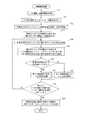
- FIG. 5 is a flowchart showing the procedure of the approximation process.
- the path dividing unit 10 acquires path information and line width information as input (S10).
- the path dividing unit 10 calculates a dividing point for dividing the path represented by the input path information into a predetermined length (S11).
- the tangent vector calculation unit 11 calculates a tangent vector and a normal vector for the path at each division point calculated by the path division unit 10 (S12).
- the contour point calculation unit 12 calculates, for each division point calculated by the path division unit 10, a contour point that is separated from the division point by a half width (S13).
- the determination unit 13 selects two adjacent dividing points among all the dividing points calculated by the path dividing unit 10 (S14), and 2 for the four contour points corresponding to the selected two dividing points.
- a distance between contour points on the same side with respect to the divided path divided by the two divided points is calculated (S15). Then, the determination unit 13 calculates a ratio of the calculated distances between the contour points, and determines whether the calculated ratio is greater than a predetermined value (S16). When the calculated ratio is larger than the predetermined value (YES in S16), a process of approximating the long partial outline by the second linear approximation method is performed (S17), and when the ratio is equal to or smaller than the predetermined value (NO in S16), The long partial outline is approximated by the first straight line approximation method (S18). Details of S17 will be described later with reference to FIG.
- the determination unit 13 determines whether or not the basic approximation calculation has been performed for all adjacent pairs of division points (S19). If not (NO in S19), the process proceeds to S14. On the other hand, when the basic approximation calculation is completed for all the groups of adjacent dividing points (YES in S19), the drawing unit 17 generates and draws an approximate curve by painting the area sandwiched between the approximated contour lines. (S20).
- FIG. 6 is a diagram showing an approximation process by the second linear approximation method corresponding to S17 of FIG.
- the control unit of the curve forming unit 16 initializes the variable n with an initial value 0 (S51).
- the intersection calculation unit 22 includes the contour points a 0 and b 0 calculated by the contour point calculation unit 12 and the tangent vectors s 0 and t 0 at the contour points a 0 and b 0 calculated by the tangent vector calculation unit 11. It is used to calculate the intersection point c 0 (S52). Then, the intersection vector calculation unit 23 calculates the intersection vector u 0 (S53).
- the control unit of the curve forming unit 16 determines whether (n + 1) is larger than d (S54). If not larger (NO in S54), 1 is added to n (S55).
- the sub-contour point calculation unit 20 calculates sub-contour points a n and b n using Equations 2 and 3 (S56).
- the tangent vector calculating section 21 the tangent vector s n in the sub-contour point a n, b n using Equation 4 and Equation 5, to calculate the t n (S57).
- intersection calculation unit 22 calculates a straight line extending tangent vector s n direction a n as a base point, an intersection point c n of both linear (S58).
- the intersection vector calculating unit 23 using Equation 6 to calculate the intersection point vector u n at the intersection c n (S59).
- each contour point and sub-contour points a 0 , a 1 , a 2 , a in the approximate curve a 0 -a 1 -a 2 -a 3 -c 3 -b 3 -b 2 -b 1 -b 0 3 , c 3 , b 3 , b 2 , b 1 , b 0 are held (S60).
- the contour points a 0 and b 0 and the tangent vectors s 0 and t 0 are known before entering the approximation process.
- c 0 is calculated by the intersection calculation unit 22, and in S53, the intersection vector u 0 is calculated by the intersection vector calculation unit 23.
- the sub-contour point calculation unit 20 calculates sub-contour points a 1 and b 1 .
- the tangent vector calculation unit 21 calculates the tangent vectors s 1 and t 1 .
- the intersection calculation unit 22 calculates the intersection point c 1.
- the intersection vector calculation unit 23 calculates the intersection vector u 1 .
- the sub-contour point calculation unit 20 calculates sub-contour points a 2 and b 2 .
- the tangent vector calculation unit 21 calculates tangent vectors s 2 and t 2 .
- the intersection calculation unit 22 calculates the intersection point c 2.
- the intersection vector calculation unit 23 calculates the intersection point vector u 2.
- the sub-contour point calculation unit 20 calculates sub-contour points a 3 and b 3 .
- the tangent vector calculation unit 21 calculates tangent vectors s 3 and t 3 .
- the intersection calculation unit 22 calculates the intersection point c 3.
- the intersection vector calculation unit 23 calculates the intersection vector u 3 .
- the path dividing unit 10 divides a path into a predetermined length.
- the path dividing unit 10 is not limited to the predetermined length, and it is sufficient that the path is divided into units suitable for approximation processing.
- the division length may be determined in consideration of the balance between the reduction in calculation load required for the approximation processing and the reproducibility of the curve to be drawn based on the approximation processing result. Specifically, in the vicinity of the inflection point of the path, it may be divided more finely than other parts, or the length of the divided path may be reduced by increasing the length of the divided path as the path is closer to a straight line. It may be uniform, or the portion where the path is a straight line may not be divided.
- the determination unit 13 determines whether or not the long partial contour line is approximated by more line segments depending on whether the ratio of the length of the long side to the short side is greater than a predetermined value. However, it is sufficient if it is possible to determine whether or not the degree of deviation between the lengths of the long side and the short side is equal to or greater than a certain level. For example, four separation points are calculated along each normal of a path passing through two adjacent division points, and separated from each division point by a predetermined distance that is not half the line width as in the above embodiment.
- the determination unit 13 determines whether or not the ratio of the length of the long side to the short side is larger than the predetermined value, but until the ratio of the long side to the short side is calculated.
- the division coefficient d is determined by Equation 1, but is not limited to this, and may be a fixed value, or a display curve for displaying the computing capability of the apparatus and an approximate curve.
- the determination unit 13 determines whether the ratio of the length of the long side to the short side is larger than the predetermined value, the predetermined value is set to 2 as an example. Rather than those, appropriate values corresponding to the reproducibility of the curve required for approximation, the curve display capability of the display for displaying the approximate curve, the calculation capability of the curve drawing device, etc. are calculated and used in advance by simulation etc. It is good as well.
- the determination unit 13 does not make a determination about a case where normals passing through two adjacent division points intersect each other between the division points and the contour points. In such a unique case where an intersection occurs, a process separate from the case where no intersection occurs may be performed. Specifically, among the partial outlines, the one that is not on the same side as the point that intersects the segment that passes through the two division points (corresponding to the long side) is approximated by a plurality of curves, and the two division points are The side on the same side as the point intersecting the passing segment (corresponding to the short side) may not be approximated.
- the path information represents, as an example, a path using a coordinate sequence of each control point of a cubic Bezier curve, but is not limited to this expression. Anything that can express (9)
- Such a recording medium includes an IC card, a hard disk, an optical disk, a flexible disk, a ROM, a flash memory, and the like.
- the distributed and distributed control program is used by being stored in a memory or the like that can be read by the processor, and the processor executes the control program to realize each function as shown in each embodiment. Will come to be.
- the processor may be compiled and executed or executed by an interpreter.
- Each functional component may be realized as a circuit that executes the function, or may be realized by executing a program by one or a plurality of processors.
- Each functional component described above is typically realized as an LSI that is an integrated circuit. These may be individually made into one chip, or may be made into one chip so as to include a part or all of them.
- the name used here is LSI, but it may also be called IC, system LSI, super LSI, or ultra LSI depending on the degree of integration.
- the method of circuit integration is not limited to LSI's, and implementation using dedicated circuitry or general purpose processors is also possible.
- An FPGA Field Programmable Gate Array
- a reconfigurable processor that can reconfigure the connection and setting of circuit cells inside the LSI may be used.
- integrated circuit technology comes out to replace LSI's as a result of the advancement of semiconductor technology or a derivative other technology, it is naturally also possible to carry out function block integration using this technology. Biotechnology can be applied.
- (11) The above-described embodiments and modifications may be partially combined. ⁇ 3. Supplement>
- the configuration of the curve drawing device as one embodiment of the present invention, and its modifications and effects will be described.
- a curve drawing apparatus is a curve drawing apparatus that linearly approximates a contour line of a curve having a width defined by a center line and a line width, and divides the center line.
- Division point calculation means for calculating a plurality of division points on the center line, and for each of the division points, two separation points that are equidistant from the division point along the normal line of the center line passing through the division point are calculated.
- each separation point calculating means and the four separation points calculated for two adjacent division points For each of the separation points calculating means and the four separation points calculated for two adjacent division points, each separation point on the same side with respect to a straight line passing through the two division points A distance calculating means for calculating a distance between each pair of separation points; and a ratio of the two distances based on a shorter one of the two calculated distances; and whether the ratio is greater than a predetermined value.
- the separation point calculating means may calculate a point separated from the division point by half of the line width as two separation points that are equidistant from the division point.
- the separation point is a point on the contour line, that is, the end point of the partial contour line and the separation point coincide with each other, the process of separately calculating the end point of the partial contour line can be omitted.
- the curve forming means approximates the shorter one of the partial contour lines by one line segment, and the dividing point calculating means is shorter of the partial contour lines when dividing the center line. It is also possible to divide so that one line segment approximating the direction becomes a predetermined length or less.
- the curve forming unit may determine the number of line segments used for the approximation according to the ratio calculated by the determining unit. Good.
- the partial contour line can be approximated by a line segment having an appropriate number of divisions according to the ratio.
- both end points of the partial contour are set as points a 0 and b 0 , and a vector s 0 is set as the center line a tangent vector at the division point corresponding to the point a 0, the vector t 0, the center line, the tangent vector at the division point corresponding to the point b 0, the point c 0, the vector s 0 as a base point to the point a 0
- an approximate curve that approximates a partial contour line by a plurality of line segments can be calculated from a simple recurrence formula. (6)
- the curve forming unit does not depend on the determination result by the determination unit, but the straight line passing through the two division points.
- a partial contour line that is not on the same side as the intersecting point may be approximated by a plurality of curves.
- a curve drawing method is defined by a center line and a line width including a dividing point calculating unit, a separation point calculating unit, a distance calculating unit, a determining unit, and a curve forming unit.
- a dividing point calculating step and the separation point calculating means calculate, for each of the dividing points, two separating points that are equidistant from the dividing point along a normal line of the center line passing through the dividing point.
- the step and the distance calculation means set the four separation points calculated for two adjacent division points as a pair of separation points on the same side with respect to a straight line passing through the two division points .
- Separation points for each pair A distance calculating step for calculating the distance between the two distances, and the determination means calculates a ratio of the two distances based on a shorter one of the two calculated distances, and whether the ratio is larger than a predetermined value.
- a curve drawing program is a curve drawing for causing a computer to function as a curve drawing device that linearly approximates a contour line of a curve having a width defined by a center line and a line width.
- a separation point calculating means for calculating two separation points that are equidistant from the dividing point along the four separation points calculated for two adjacent dividing points with respect to a straight line passing through the two dividing points
- a distance calculation means for calculating the distance between each pair of separation points when the separation points on the same side are a pair, and the shorter one of the two calculated distances as a reference Calculating a ratio of two distances, and determining means for determining whether or not the ratio is greater than a predetermined value; and when the ratio is determined to be greater than a predetermined value;
- An integrated circuit is an integrated circuit used in a curve drawing device that linearly approximates a contour line of a curve having a width, which is defined by a center line and a line width.
- Dividing point calculating means for calculating a plurality of dividing points on the center line for dividing the line, and for each of the dividing points, two equal distances from the dividing point along the normal line of the center line passing through the dividing point.
- the separation point calculation means for calculating the separation point and the four separation points calculated for the two adjacent division points the separation points on the same side with respect to the straight line passing through the two division points are paired.
- a distance calculation means for calculating the distance between each set of separation points, and a ratio of the two distances based on the shorter of the two calculated distances, and the ratio is a predetermined value Judgment whether or not it is larger And when the ratio is determined to be greater than a predetermined value, the longer one of the partial contour lines that are sandwiched between the normal lines passing through the two division points in the contour line is selected from the shorter one. And curve forming means for approximating with many line segments.
- the curve drawing apparatus calculates outlines of character fonts, figures, etc. using a simple method with a lower calculation load than before, and displays such character fonts, figures, etc. on a display. It is suitable for an apparatus such as an information processing terminal.
Landscapes
- Engineering & Computer Science (AREA)
- Physics & Mathematics (AREA)
- General Physics & Mathematics (AREA)
- Theoretical Computer Science (AREA)
- Data Mining & Analysis (AREA)
- Pure & Applied Mathematics (AREA)
- Mathematical Optimization (AREA)
- Mathematical Analysis (AREA)
- Mathematical Physics (AREA)
- Computational Mathematics (AREA)
- Computer Hardware Design (AREA)
- Algebra (AREA)
- Databases & Information Systems (AREA)
- Software Systems (AREA)
- General Engineering & Computer Science (AREA)
- Image Generation (AREA)
- Image Processing (AREA)
Abstract
Priority Applications (3)
| Application Number | Priority Date | Filing Date | Title |
|---|---|---|---|
| CN201280001516.7A CN102918566B (zh) | 2011-04-15 | 2012-04-13 | 曲线描绘装置、曲线描绘方法及集成电路 |
| JP2013509802A JPWO2012140910A1 (ja) | 2011-04-15 | 2012-04-13 | 曲線描画装置、曲線描画方法、曲線描画プログラム及び集積回路 |
| US13/699,157 US9092905B2 (en) | 2011-04-15 | 2012-04-13 | Curve rendering device, curve rendering method, curve rendering program, and integrated circuit |
Applications Claiming Priority (2)
| Application Number | Priority Date | Filing Date | Title |
|---|---|---|---|
| JP2011090772 | 2011-04-15 | ||
| JP2011-090772 | 2011-04-15 |
Publications (2)
| Publication Number | Publication Date |
|---|---|
| WO2012140910A1 true WO2012140910A1 (fr) | 2012-10-18 |
| WO2012140910A9 WO2012140910A9 (fr) | 2013-10-10 |
Family
ID=47009099
Family Applications (1)
| Application Number | Title | Priority Date | Filing Date |
|---|---|---|---|
| PCT/JP2012/002590 Ceased WO2012140910A1 (fr) | 2011-04-15 | 2012-04-13 | Dispositif de traçage de courbe, procédé de traçage de courbe, programme de traçage de courbe et circuit intégré |
Country Status (4)
| Country | Link |
|---|---|
| US (1) | US9092905B2 (fr) |
| JP (1) | JPWO2012140910A1 (fr) |
| CN (1) | CN102918566B (fr) |
| WO (1) | WO2012140910A1 (fr) |
Families Citing this family (12)
| Publication number | Priority date | Publication date | Assignee | Title |
|---|---|---|---|---|
| US9153049B2 (en) * | 2012-08-24 | 2015-10-06 | International Business Machines Corporation | Resource provisioning using predictive modeling in a networked computing environment |
| KR20150145774A (ko) * | 2014-06-19 | 2015-12-31 | 삼성전자주식회사 | 필기 애니메이션을 제공하는 전자장치 및 방법 |
| US10347016B2 (en) * | 2016-01-12 | 2019-07-09 | Monotype Imaging Inc. | Converting font contour curves |
| EP3435358A4 (fr) * | 2016-05-20 | 2019-03-20 | Aisin Aw Co., Ltd. | Système et programme d'affichage de carte |
| CN109891461B (zh) * | 2016-10-25 | 2023-02-03 | 三菱电机株式会社 | 地图数据生成装置、终端装置及地图数据生成方法 |
| CN107049347B (zh) * | 2017-06-14 | 2020-11-03 | 珠海和佳医疗设备股份有限公司 | X射线机管电流的校准方法 |
| US10650586B2 (en) * | 2017-08-10 | 2020-05-12 | Outward, Inc. | Automated mesh generation |
| US10936792B2 (en) | 2017-12-21 | 2021-03-02 | Monotype Imaging Inc. | Harmonizing font contours |
| KR102653951B1 (ko) * | 2018-09-06 | 2024-04-02 | 삼성전자주식회사 | 반도체 소자의 레이아웃 패턴 분할 방법 및 이를 포함하는 광 근접 보정 방법 |
| CN111443864B (zh) * | 2020-04-14 | 2023-03-07 | 重庆赋比兴科技有限公司 | 基于iOS的曲线绘制方法 |
| US12026840B2 (en) * | 2021-05-21 | 2024-07-02 | Occipital, Inc. | System for generation of floor plans and three-dimensional models |
| CN115640623B (zh) * | 2022-10-13 | 2026-03-17 | 郑州大学 | 一种模具复杂型面上排气通道特征自动生成方法及系统 |
Citations (2)
| Publication number | Priority date | Publication date | Assignee | Title |
|---|---|---|---|---|
| JPH04174494A (ja) * | 1990-11-07 | 1992-06-22 | Nec Off Syst Ltd | 文字発生方式 |
| JPH0785293A (ja) * | 1993-06-26 | 1995-03-31 | Just Syst Corp | 情報処理装置 |
Family Cites Families (10)
| Publication number | Priority date | Publication date | Assignee | Title |
|---|---|---|---|---|
| US5408598A (en) * | 1991-05-23 | 1995-04-18 | International Business Machines Corporation | Method for fast generation of parametric curves employing a pre-calculated number of line segments in accordance with a determined error threshold |
| EP0604685A1 (fr) * | 1992-12-28 | 1994-07-06 | Océ-Nederland B.V. | Méthode pour modifier l'aspect gras des caractères |
| US5381521A (en) * | 1993-05-14 | 1995-01-10 | Microsoft Corporation | System and method of rendering curves |
| JPH11345344A (ja) | 1998-06-01 | 1999-12-14 | Matsushita Electric Ind Co Ltd | 3次曲線を与える方法及び装置 |
| DE19901934C2 (de) * | 1999-01-19 | 2001-07-19 | Heidelberger Druckmasch Ag | Verfahren zur Erzeugung eines Rahmens für grafische Objekte, die durch Bezier-Kurven beschrieben sind |
| US6501475B1 (en) * | 1999-10-22 | 2002-12-31 | Dynalab Inc. | Glyph-based outline font generation independent of resolution |
| US7239319B2 (en) * | 2004-08-27 | 2007-07-03 | Microsoft Corporation | Rendering outline fonts |
| GB0818278D0 (en) | 2008-10-06 | 2008-11-12 | Advanced Risc Mach Ltd | Graphics processing systems |
| US8643650B1 (en) * | 2009-08-13 | 2014-02-04 | Adobe Systems Incorporated | System and method for approximating parametric curves using optimal number of segments |
| US20110285736A1 (en) * | 2010-05-21 | 2011-11-24 | Kilgard Mark J | Decomposing cubic bèzier segments for tessellation-free stencil filling |
-
2012
- 2012-04-13 WO PCT/JP2012/002590 patent/WO2012140910A1/fr not_active Ceased
- 2012-04-13 JP JP2013509802A patent/JPWO2012140910A1/ja not_active Ceased
- 2012-04-13 CN CN201280001516.7A patent/CN102918566B/zh not_active Expired - Fee Related
- 2012-04-13 US US13/699,157 patent/US9092905B2/en not_active Expired - Fee Related
Patent Citations (2)
| Publication number | Priority date | Publication date | Assignee | Title |
|---|---|---|---|---|
| JPH04174494A (ja) * | 1990-11-07 | 1992-06-22 | Nec Off Syst Ltd | 文字発生方式 |
| JPH0785293A (ja) * | 1993-06-26 | 1995-03-31 | Just Syst Corp | 情報処理装置 |
Also Published As
| Publication number | Publication date |
|---|---|
| JPWO2012140910A1 (ja) | 2014-07-28 |
| CN102918566A (zh) | 2013-02-06 |
| CN102918566B (zh) | 2016-01-06 |
| US20130100138A1 (en) | 2013-04-25 |
| WO2012140910A9 (fr) | 2013-10-10 |
| US9092905B2 (en) | 2015-07-28 |
Similar Documents
| Publication | Publication Date | Title |
|---|---|---|
| WO2012140910A1 (fr) | Dispositif de traçage de courbe, procédé de traçage de courbe, programme de traçage de courbe et circuit intégré | |
| KR101337758B1 (ko) | 3차원 그래픽 하드웨어를 이용한 2차원 그래픽 렌더링 동안의 버텍스 포인트 제거 | |
| US8659599B2 (en) | System and method for generating a manifold surface for a 3D model of an object using 3D curves of the object | |
| CN106251384B (zh) | 使用三角形的递归再分的细分方法 | |
| KR101114002B1 (ko) | 2차원 벡터 그래픽스 삼각형화 시스템 및 그 방법 | |
| US12266051B2 (en) | UV mapping on 3D objects with the use of artificial intelligence | |
| US10019817B2 (en) | Example-based edge-aware directional texture painting | |
| US20240257470A1 (en) | Avatar personalization using image generation | |
| US20160125649A1 (en) | Rendering apparatus and rendering method | |
| US10885681B2 (en) | Method and apparatus for performing path stroking | |
| US11989807B2 (en) | Rendering scalable raster content | |
| US12073503B2 (en) | Apparatus and method to generate an animated graphical object | |
| CN114724148A (zh) | 生成模型、提取特征的方法、装置、设备、介质及产品 | |
| CN101819641A (zh) | 将字符与图像的采样网格对齐的方法 | |
| US11776179B2 (en) | Rendering scalable multicolored vector content | |
| González et al. | Simplification method for textured polygonal meshes based on structural appearance | |
| US20240346734A1 (en) | Graph simulation for facial micro features with dynamic animation | |
| KR20160086622A (ko) | 스트로크 기반의 이미지 렌더링 장치, 방법 및 컴퓨터 프로그램 | |
| US20240346733A1 (en) | Graph simulation for facial micro features with dynamic animation | |
| US20250117989A1 (en) | Vector path trajectory imitation | |
| Behar et al. | Dynamic minkowski sums under scaling | |
| US20240420424A1 (en) | Gradient mesh generation for digital images | |
| Quispe | Discrete indicator functions on particle-based fluids | |
| Lee et al. | Trash removal algorithm for fast construction of the elliptic Gabriel graph using Delaunay triangulation | |
| CN119741418A (zh) | 光线跟踪系统中的相交测试 |
Legal Events
| Date | Code | Title | Description |
|---|---|---|---|
| WWE | Wipo information: entry into national phase |
Ref document number: 201280001516.7 Country of ref document: CN |
|
| ENP | Entry into the national phase |
Ref document number: 2013509802 Country of ref document: JP Kind code of ref document: A |
|
| WWE | Wipo information: entry into national phase |
Ref document number: 13699157 Country of ref document: US |
|
| 121 | Ep: the epo has been informed by wipo that ep was designated in this application |
Ref document number: 12771643 Country of ref document: EP Kind code of ref document: A1 |
|
| NENP | Non-entry into the national phase |
Ref country code: DE |
|
| 122 | Ep: pct application non-entry in european phase |
Ref document number: 12771643 Country of ref document: EP Kind code of ref document: A1 |