WO2012140991A1 - Support de fibre optique - Google Patents
Support de fibre optique Download PDFInfo
- Publication number
- WO2012140991A1 WO2012140991A1 PCT/JP2012/056990 JP2012056990W WO2012140991A1 WO 2012140991 A1 WO2012140991 A1 WO 2012140991A1 JP 2012056990 W JP2012056990 W JP 2012056990W WO 2012140991 A1 WO2012140991 A1 WO 2012140991A1
- Authority
- WO
- WIPO (PCT)
- Prior art keywords
- optical fiber
- movable base
- base portion
- lid
- alignment
- Prior art date
- Legal status (The legal status is an assumption and is not a legal conclusion. Google has not performed a legal analysis and makes no representation as to the accuracy of the status listed.)
- Ceased
Links
Images






Classifications
-
- G—PHYSICS
- G02—OPTICS
- G02B—OPTICAL ELEMENTS, SYSTEMS OR APPARATUS
- G02B6/00—Light guides; Structural details of arrangements comprising light guides and other optical elements, e.g. couplings
- G02B6/24—Coupling light guides
-
- G—PHYSICS
- G02—OPTICS
- G02B—OPTICAL ELEMENTS, SYSTEMS OR APPARATUS
- G02B6/00—Light guides; Structural details of arrangements comprising light guides and other optical elements, e.g. couplings
- G02B6/44—Mechanical structures for providing tensile strength and external protection for fibres, e.g. optical transmission cables
- G02B6/4439—Auxiliary devices
-
- G—PHYSICS
- G02—OPTICS
- G02B—OPTICAL ELEMENTS, SYSTEMS OR APPARATUS
- G02B6/00—Light guides; Structural details of arrangements comprising light guides and other optical elements, e.g. couplings
- G02B6/24—Coupling light guides
- G02B6/255—Splicing of light guides, e.g. by fusion or bonding
- G02B6/2555—Alignment or adjustment devices for aligning prior to splicing
-
- G—PHYSICS
- G02—OPTICS
- G02B—OPTICAL ELEMENTS, SYSTEMS OR APPARATUS
- G02B6/00—Light guides; Structural details of arrangements comprising light guides and other optical elements, e.g. couplings
- G02B6/24—Coupling light guides
- G02B6/36—Mechanical coupling means
- G02B6/3616—Holders, macro size fixtures for mechanically holding or positioning fibres, e.g. on an optical bench
-
- G—PHYSICS
- G02—OPTICS
- G02B—OPTICAL ELEMENTS, SYSTEMS OR APPARATUS
- G02B6/00—Light guides; Structural details of arrangements comprising light guides and other optical elements, e.g. couplings
- G02B6/24—Coupling light guides
- G02B6/36—Mechanical coupling means
- G02B6/3628—Mechanical coupling means for mounting fibres to supporting carriers
- G02B6/3632—Mechanical coupling means for mounting fibres to supporting carriers characterised by the cross-sectional shape of the mechanical coupling means
- G02B6/3636—Mechanical coupling means for mounting fibres to supporting carriers characterised by the cross-sectional shape of the mechanical coupling means the mechanical coupling means being grooves
Definitions
- the present invention relates to an optical fiber holder that holds a plurality of optical fibers in alignment.
- An optical fiber holder is: A holder body; An alignment mechanism having a base formed on the holder main body, a movable base disposed to overlap the base, and an alignment lid disposed to overlap the movable base; With The movable base portion and the alignment lid are connected to the holder body so as to be rotatable about the same axis, respectively. Between the movable base portion and the alignment lid overlapped with each other, a slit opposite to the connection portion with the holder main body is opened and a plurality of optical fibers can be accommodated in parallel. The plurality of optical fibers accommodated in the slit in a state in which the movable base portion and the alignment lid are overlapped on the base portion are aligned in an accommodating portion provided in the holder body.
- At least one of the movable base part and the alignment lid may be provided with a protrusion for narrowing the opening width of the slit at a part of the slit on the side opposite to the connection part.
- the side of the alignment mechanism portion in the holder body is connected to the holder body so as to be rotatable about the same axis as the rotation axis of the movable base portion and the alignment lid, and the holder body
- a holding lid is provided for pressing and holding the optical fibers aligned in the accommodating portion;
- the movable base portion and the alignment lid may be stopped at a position of a rotation angle smaller than a rotation angle of the holding lid with respect to the holder body.
- the base portion and the movable base portion, and the movable base portion and the alignment lid can be adsorbed, respectively, and the adsorbing force between the movable base portion and the alignment lid is determined between the base portion and the movable base portion. It may be smaller than the adsorption force.
- the base portion and the movable base portion, and the movable base portion and the alignment lid may be attracted by a magnetic force by a magnet, respectively.
- a plurality of optical fibers are sequentially inserted into the slit formed by the movable base portion and the alignment lid from the opening portion of the slit, and the movable base portion and the alignment lid are accommodated in the base portion of the holder body.
- the plurality of optical fibers accommodated in the slit can be easily aligned in the accommodating portion of the holder body.
- operativity at the time of aligning a some optical fiber in order to perform a terminal process and a fusion splicing process can be improved significantly.
- a plurality of optical fibers are sequentially installed from the back side of the slit. It can be accommodated in a state of being aligned in parallel so as to be naturally laminated.
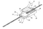
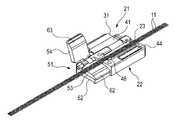
- FIG. 1 It is a perspective view showing one embodiment of an optical fiber holder concerning the present invention. It is a top view which shows the optical fiber holder of FIG. It is a side view which shows the optical fiber holder of FIG. It is the side view seen from the alignment mechanism part side which shows the optical fiber holder of FIG. It is a perspective view which shows the structure of the optical fiber holder of FIG. It is a perspective view which shows the structure of the optical fiber holder of FIG. It is a perspective view which shows the structure of the optical fiber holder of FIG. It is the side view seen from the alignment mechanism part side which shows the structure of the optical fiber holder of FIG. It is a perspective view which shows the alignment holding
- optical fiber holder holds a plurality of single-core optical fibers in alignment.
- covered the outer periphery of the glass fiber which consists of a core and a clad with resin is illustrated and demonstrated.
- the optical fiber holder 21 holds a plurality of optical fibers (optical fibers) 11 having a single outer diameter of 250 ⁇ m (12 in this example).
- the optical fiber holder 21 removes the coating of the end portions of the plurality of optical fiber core wires 11 to expose a glass fiber having an outer diameter of 125 ⁇ m, and when the glass fiber is cut at a predetermined position, The fiber core wire 11 is aligned and held. Further, the optical fiber holder 21 is fused while holding the optical fiber core wire 11 when the end surfaces of the glass fibers exposed at the end portion of the optical fiber core wire 11 are fused together by a fusion splicer. It can also be set on a connected machine.
- the optical fiber holder 21 has a holder body 22.
- An accommodation groove (accommodating portion) 23 that accommodates the plurality of optical fiber core wires 11 in parallel is formed on the upper surface of the holder body 22 along the axial direction.
- a core wire holding lid (holding lid) 31 is provided on one side of the holder body 22.
- the core wire holding lid 31 has a hinge portion 34, and the hinge portion 34 is disposed in a holding groove 35 formed in the holder main body 22.
- the holder main body 22 is provided with a connecting pin 38 that penetrates the holding groove 35, and the connecting pin 38 is inserted through an insertion hole (not shown) formed in the hinge portion 34.
- the core wire holding lid 31 is connected to the holder main body 22 so as to be rotatable within a range of about 180 ° about the axis of the connecting pin 38.
- the core wire holding lid 31 is disposed so as to cover the upper portion of the accommodation groove 23 by being rotated toward the upper surface side of the holder main body 22.
- the core wire holding lid 31 is provided with a pressing plate portion 41 made of an elastic material such as rubber on the surface facing the holder main body 22. Then, by rotating the core wire holding lid 31 toward the upper surface side of the holder main body 22, the pressing plate portion 41 is disposed on the upper portion of the housing groove 23.
- the holder main body 22 is provided with a magnet 44 on the upper surface on the side opposite to the one side to which the core wire holding lid 31 is connected, and when the core wire holding lid 31 is arranged on the upper surface of the holder main body 22.
- the core wire holding lid 31 is in contact with or close to the magnet 44.
- the core wire holding lid 31 is made of a magnetic material such as iron, and is attracted by the magnetic force of the magnet 44 while being arranged on the upper surface of the holder body 22.
- the optical fiber holder 21 having the above structure includes the core wire holding lid 31 that is attracted to the holder main body 22 by the magnetic force of the magnet 44 and presses and holds the optical fiber core wire 11 in the housing groove 23. .
- a guide portion 46 is projected from a position on the upper surface of the holder body 22 where the core wire holding lid 31 does not overlap.
- the guide portion 46 is formed at the edge of the receiving groove 23 on the side opposite to the connection side of the core wire holding lid 31 with the holder main body 22.
- the optical fiber holder 21 includes an alignment mechanism 51 on one end side.
- the alignment mechanism portion 51 has a plate-like base portion 52 that is a part of the holder body 22.
- the base portion 52 is formed on one end side of the holder main body 22, and the movable base portion 53 and the alignment lid 54 are disposed on the base portion 52.
- the movable base portion 53 and the alignment lid 54 have hinge portions 55 and 56, respectively, and these hinge portions 55 and 56 are disposed in a holding groove 57 formed in the holder main body 22.
- the connecting pin 38 described above also penetrates the holding groove 57, and the connecting pin 38 is inserted into an insertion hole (not shown) formed in the hinge portions 55 and 56.
- the movable base 53 and the alignment lid 54 are connected to the holder body 22 so as to be rotatable about the axis of the connection pin 38.
- the rotation angle of the alignment lid 54 with respect to the holder main body 22 is about 100 ° to 120 °, which is smaller than 180 °, which is the rotation angle of the core wire holding lid 31 with respect to the holder main body 22.
- rotation of the alignment lid 54 in the opening direction is restricted and stops at the hitting position.
- the rotation angle of the movable base 53 with respect to the holder main body 22 is set to about 100 ° to 120 °, which is smaller than 180 ° which is the rotation angle of the core wire holding lid 31 with respect to the holder main body 22.
- the rotation angles of the movable base 53 and the alignment lid 54 are not limited to the above angles, and may be any angles that are smaller than the rotation angle of the core wire holding lid 31. That is, when the rotation angle of the core wire holding lid 31 with respect to the holder body 22 is larger than 180 °, the rotation angles of the movable base portion 53 and the alignment lid 54 may be 180 °.
- the movable base portion 53 and the alignment lid 54 are in a state of being overlapped with each other, the connecting sides of the opposing surfaces to the holder body 22 are in contact with each other, and the contacting surfaces are in contact with each other.
- a slit 61 is formed on the side opposite to the connection side with the holder body 22 rather than the location. Further, the opposing surfaces of the movable base portion 53 and the alignment lid 54 are gradually separated toward the respective side edges of the movable base portion 53 and the alignment lid 54 on the opposite side of the slit 61 from the connection side with the holder body 22.
- a tapered surface 62 (first tapered surface) and a tapered surface 63 (second tapered surface) are respectively formed.
- the slit 61 formed between the opposed surfaces of the movable base portion 53 and the alignment lid 54 has a width slightly larger than the outer diameter of the optical fiber core wire 11, and a plurality of slits 61 are formed from the side edge side of the slit 61.
- (12) optical fiber core wires 11 can be inserted in order. When the optical fiber core wire 11 is inserted into the slit 61, the optical fiber core wire 11 is smoothly guided to the slit 61 by the tapered surfaces 62 and 63. When a plurality of optical fiber cores 11 are sequentially inserted into the slits 61, these optical fiber cores 11 are accommodated in the slits 61.
- a magnet 64 is provided on the upper surface of the base portion 52, and a magnet 65 is provided on the surface of the movable base portion 53 on the base portion 52 side. Accordingly, the movable base portion 53 is attracted to the base portion 52 by the magnetic force between the magnets 64 and 65 while being disposed on the upper surface of the base portion 52.
- the movable base 53 is made of a nonmagnetic material such as aluminum.
- the alignment lid 54 is made of a magnetic material such as iron.
- the alignment lid 54 is attracted to the movable base portion 53 by the magnetic force of the magnet 65 provided on the movable base portion 53 and aligned with the movable base portion 53.
- the lid 54 is adsorbed. Note that the magnetic force of the magnet 65 acting on the alignment lid 54 acts indirectly via the movable base portion 53 made of a non-magnetic material. Therefore, the attracting force of the alignment lid 54 attracted to the movable base 53 by the magnetic force of the magnet 65 is weaker than the attracting force of the movable base 53 to be attracted to the base 52 by the magnetic force between the magnets 64 and 65.
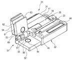
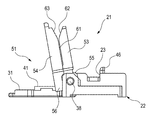
- the core wire holding lid 31 is rotated to open the upper surface side of the holder main body 22. Further, the alignment lid 54 and the movable base 53 of the alignment mechanism 51 are rotated in a state where they are overlapped. If it does in this way, the opening side of the slit 61 formed between the alignment lid 54 and the movable base part 53 will be in the state which faced upwards (refer FIG.5 and FIG.6).
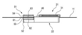
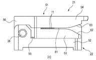
- the optical fiber core wires 11 are inserted into the slit 61 so as to be slid one by one from the upper side. At this time, the optical fiber core wire 11 is smoothly guided to the slit 61 by the tapered surfaces 62 and 63. Then, only by inserting the plurality of optical fiber cores 11 into the slit 61, as shown in FIG. 7A, the plurality of optical fiber cores 11 are naturally laminated in order from the back side of the slit 61. The plurality of optical fiber core wires 11 are accommodated in the slit 61 in a state of being aligned in parallel.
- the movable base 53 and the alignment lid 54 that overlap with each other to form the slit 61 are rotated toward the base 52 and overlapped with the base 52. Then, the magnets 64 and 65 of the base 52 and the movable base 53 are attracted to each other. As a result, the movable base portion 53 and the alignment lid 54 are held by the base portion 52. At this time, since the core wire holding lid 31 having a rotation angle larger than the rotation angle of the movable base portion 53 and the alignment lid 54 with respect to the holder body 22 is open, the optical fiber core accommodated in the slit 61 is opened. The movable base 53 and the alignment lid 54 can be rotated without causing the wire 11 to interfere with the core wire holding lid 31.
- the plurality of optical fiber core wires 11 that are accommodated in parallel with the slit 61 are accommodated in the holder body 22. Is accommodated in the receiving groove 23. At this time, the plurality of optical fiber core wires 11 housed in the slit 61 are guided to the housing groove 23 without jumping out of the slit 61 by the guide portion 46 formed at the edge of the housing groove 23.
- the core wire holding lid 31 is rotated and overlapped on the upper surface of the holder main body 22. At this time, if the optical fiber cores 11 in the receiving groove 23 are not arranged in a line, the optical fiber cores 11 in the receiving groove 23 are averaged with a finger and arranged in a line.
- the core wire holding lid 31 is placed on the upper surface of the holder main body 22, the core wire holding lid 31 is attracted by the magnet 44 while being arranged on the upper surface of the holder main body 22. Thereby, the plurality of optical fiber core wires 11 are pressed and held by the pressing plate 41 of the core wire holding lid 31.
- a plurality of optical fiber cores 11 are held in alignment with the optical fiber holder 21, thereby removing the end coating from the optical fiber core 11 to expose the glass fiber.
- it can be set in a fusion splicer to smoothly perform the fusion splicing process between the end faces of the glass fibers.
- the core wire holding lid 31 When taking out the optical fiber core wire 11 from the optical fiber holder 21, first, the core wire holding lid 31 is rotated to open the upper surface side of the holder main body 22. If it does in this way, holding of optical fiber core wire 11 pressed and held to holder main part 22 by core wire maintenance lid 31 will be canceled.
- the alignment lid 54 is rotated and separated from the movable base portion 53, the slit 61 formed between the opposing surfaces of the alignment lid 54 and the movable base portion 53 is opened. Therefore, the plurality of optical fiber cores 11 accommodated in the slit 61 are exposed, and the optical fiber cores 11 can be easily taken out from the optical fiber holder 21.
- the plurality of optical fiber cores 11 are sequentially arranged from the opening portion of the slit 61 to the slit 61 formed by the movable base portion 53 and the alignment lid 54.
- the plurality of optical fiber cores 11 accommodated in the slit 61 are easily aligned in the accommodation groove 23 of the holder body 22 by inserting and accommodating, and overlapping the movable base portion 53 and the alignment lid 54 on the base portion 52. be able to.
- the workability at the time of aligning the plurality of optical fiber cores 11 in order to perform terminal processing or fusion splicing processing can be greatly improved compared to the conventional one.
- the movable base 53 and the alignment lid 54 that are overlapped can be rotated to stop the opening of the slit 61 at a position facing upward, so that the optical fiber core is opened from the opening of the slit 61.
- a plurality of optical fiber core wires 11 can be accommodated in a state of being aligned in parallel so as to be naturally stacked in order from the back side of the slit 61.
- the optical fiber core wire 11 is provided with the core wire holding lid 31 that presses and holds the optical fiber core wire 11 against the holder body 22, but the function of holding the optical fiber core wire 11 is provided in the alignment mechanism 51. You may have it.
- the alignment lid 54 with respect to the movable base 53 is divided into two stages: a slit forming position where the slit 61 is formed and a fiber clamping position where the optical fiber core wire 11 in the slit 61 is pressed against the movable base 53 and held. It may be displaceable.
- the holding force of the movable base portion 53 with respect to the base portion 52 and the holding force of the alignment lid 54 with respect to the movable base portion 53 are generated by the magnetic attraction force of the magnets 64 and 65.
- the holding force may be obtained by the engagement means used.
- the opening of the slit 61 is formed at the boundary of the tapered surface 62 of the movable base 53 with the slit 61 and on the opposite side of the slit 61 from the connecting portion with the holder main body 22.
- a protrusion 62a that narrows the width is provided.
- the protrusion 62a can be provided on the entire edge of the boundary between the tapered surface 62 and the slit 61 along the axial direction of the movable base 53, or can be provided on at least a part of the boundary.
- the protrusions 62a By providing the protrusions 62a, when the movable base portion 53 and the alignment lid 54 are rotated to the base portion 52 side, the plurality of optical fiber core wires 11 accommodated in the slit 61 jump out from the opening portion of the slit 61. Can be prevented, and workability is further improved. Since the magnetic force of the magnet 65 acting on the alignment lid 54 acts indirectly via the movable base portion 53 made of a non-magnetic material, the attracting force of the alignment lid 54 attracted to the movable base portion 53 is relatively low. weak.
- the optical fiber core wire 11 can be accommodated in the slit 61 without being interrupted by the protrusion 62 a by slightly opening the gap between the movable base portion 53 and the alignment lid 54 and expanding the slit 61.
- the height of the protrusion 62a is preferably about 100 ⁇ m.
- the taper surface 62 of the movable base portion 53 is provided with a projection 62a that narrows a part of the opening width of the opening of the slit 61.
- the taper surface 63 of the alignment lid 54 or the taper surfaces 62, 63 is provided. Protrusions may be provided on both.
- Optical fiber core wire (optical fiber) 21: Optical fiber holder 22: Holder body 23: Accommodating groove (accommodating portion) 31: Core wire holding lid 51: Alignment mechanism portion 52: Base portion 53: Movable base portion 54: Alignment lid 61: Slit 64, 65: Magnet
Landscapes
- Physics & Mathematics (AREA)
- General Physics & Mathematics (AREA)
- Optics & Photonics (AREA)
- Engineering & Computer Science (AREA)
- Plasma & Fusion (AREA)
- Mechanical Coupling Of Light Guides (AREA)
- Light Guides In General And Applications Therefor (AREA)
- Optical Couplings Of Light Guides (AREA)
Abstract
Priority Applications (5)
| Application Number | Priority Date | Filing Date | Title |
|---|---|---|---|
| US14/004,185 US9052487B2 (en) | 2011-04-15 | 2012-03-19 | Optical fiber holder |
| KR1020137027078A KR101862901B1 (ko) | 2011-04-15 | 2012-03-19 | 광섬유 홀더 |
| JP2013509837A JP5899562B2 (ja) | 2011-04-15 | 2012-03-19 | 光ファイバホルダ |
| CN201280018661.6A CN103477259B (zh) | 2011-04-15 | 2012-03-19 | 光纤支架 |
| AU2012244038A AU2012244038B2 (en) | 2011-04-15 | 2012-03-19 | Optical fiber holder |
Applications Claiming Priority (2)
| Application Number | Priority Date | Filing Date | Title |
|---|---|---|---|
| JP2011091130 | 2011-04-15 | ||
| JP2011-091130 | 2011-04-15 |
Publications (1)
| Publication Number | Publication Date |
|---|---|
| WO2012140991A1 true WO2012140991A1 (fr) | 2012-10-18 |
Family
ID=47009173
Family Applications (1)
| Application Number | Title | Priority Date | Filing Date |
|---|---|---|---|
| PCT/JP2012/056990 Ceased WO2012140991A1 (fr) | 2011-04-15 | 2012-03-19 | Support de fibre optique |
Country Status (6)
| Country | Link |
|---|---|
| US (1) | US9052487B2 (fr) |
| JP (1) | JP5899562B2 (fr) |
| KR (1) | KR101862901B1 (fr) |
| CN (1) | CN103477259B (fr) |
| AU (1) | AU2012244038B2 (fr) |
| WO (1) | WO2012140991A1 (fr) |
Cited By (4)
| Publication number | Priority date | Publication date | Assignee | Title |
|---|---|---|---|---|
| JP2014174509A (ja) * | 2013-03-13 | 2014-09-22 | Hitachi Metals Ltd | 光ファイバホルダ及びその構成方法 |
| CN107850734A (zh) * | 2016-04-19 | 2018-03-27 | 罗春晖 | 一体化光纤预处理装置 |
| WO2023085081A1 (fr) * | 2021-11-11 | 2023-05-19 | 住友電工オプティフロンティア株式会社 | Support de fibre optique et dispositif d'épissage par fusion |
| WO2024084894A1 (fr) * | 2022-10-21 | 2024-04-25 | 住友電工オプティフロンティア株式会社 | Élément d'alignement |
Families Citing this family (16)
| Publication number | Priority date | Publication date | Assignee | Title |
|---|---|---|---|---|
| US8991263B2 (en) * | 2011-03-08 | 2015-03-31 | The United States Of America As Represented By The Secretary Of The Army | Fiber snubbing clamp using magnetic gripping action |
| CN104503032A (zh) * | 2014-12-09 | 2015-04-08 | 蚌埠吉新通讯机械有限公司 | 一种用于单根光纤临时对接的单芯对准器 |
| JP6628247B2 (ja) * | 2016-05-19 | 2020-01-08 | Seiオプティフロンティア株式会社 | 光ファイバ融着接続部の補強装置およびそれを備えた融着接続機 |
| CN114200586A (zh) * | 2016-09-09 | 2022-03-18 | Sei光学前沿株式会社 | 光纤保持架 |
| JP6244491B1 (ja) * | 2017-03-06 | 2017-12-06 | 株式会社フジクラ | 光ファイバ切断装置 |
| KR200490967Y1 (ko) * | 2018-08-07 | 2020-03-02 | 주식회사 에이제이월드 | 광케이블용 집합 장치 |
| US11614586B2 (en) * | 2018-08-23 | 2023-03-28 | Afl Telecommunications Llc | Optical fiber mass splice methods and assemblies |
| CN109856725B (zh) * | 2018-12-13 | 2024-04-02 | 南京吉隆光纤通信股份有限公司 | 一种双尾纤夹具 |
| CN110471146B (zh) * | 2019-08-29 | 2024-08-02 | 广州奥鑫通讯设备有限公司 | 一种光纤耦合器测试用工装结构件 |
| EP4031913A4 (fr) * | 2019-09-18 | 2023-10-18 | Corning Research & Development Corporation | Outils et procédés d'épissage de ruban |
| WO2021133737A1 (fr) * | 2019-12-23 | 2021-07-01 | Commscope Technologies Llc | Systèmes et procédés de traitement de fibre optique |
| EP4127799B1 (fr) * | 2020-03-31 | 2025-11-19 | CommScope Technologies LLC | Systèmes de gestion de câbles à fibres optiques |
| KR102750477B1 (ko) * | 2020-05-20 | 2025-01-03 | 가부시키가이샤후지쿠라 | 광섬유 절단기 및 광섬유 절단 방법 |
| KR102325582B1 (ko) * | 2020-12-02 | 2021-11-15 | 유씨엘스위프트(주) | 광섬유 리본화 접착 도포구 |
| US12585077B2 (en) | 2021-01-27 | 2026-03-24 | Afl Telecommunications Llc | Fiber optic housing and clip |
| CN114114555B (zh) * | 2021-10-25 | 2024-08-23 | 武汉理工大学 | 一种多维度无损止转型光纤旋转连接装置及使用方法 |
Citations (2)
| Publication number | Priority date | Publication date | Assignee | Title |
|---|---|---|---|---|
| JPH07218753A (ja) * | 1994-02-04 | 1995-08-18 | Fujikura Ltd | 光ファイバの融着接続方法と融着接続機 |
| JP2003177267A (ja) * | 2001-12-07 | 2003-06-27 | Olympus Optical Co Ltd | 光ファイバ整列装置及び光ファイバ整列方法 |
Family Cites Families (3)
| Publication number | Priority date | Publication date | Assignee | Title |
|---|---|---|---|---|
| JP4535219B2 (ja) * | 2001-06-12 | 2010-09-01 | 住友電気工業株式会社 | 光ファイバ被覆除去装置 |
| JP5113344B2 (ja) * | 2006-04-28 | 2013-01-09 | 株式会社フジクラ | 光ファイバホルダ及びその使用方法 |
| US7519260B1 (en) * | 2007-12-28 | 2009-04-14 | Applied Optoelectronics, Inc. | Coaxial optoelectronic device separation apparatus and method |
-
2012
- 2012-03-19 WO PCT/JP2012/056990 patent/WO2012140991A1/fr not_active Ceased
- 2012-03-19 CN CN201280018661.6A patent/CN103477259B/zh active Active
- 2012-03-19 AU AU2012244038A patent/AU2012244038B2/en active Active
- 2012-03-19 US US14/004,185 patent/US9052487B2/en active Active
- 2012-03-19 JP JP2013509837A patent/JP5899562B2/ja active Active
- 2012-03-19 KR KR1020137027078A patent/KR101862901B1/ko active Active
Patent Citations (2)
| Publication number | Priority date | Publication date | Assignee | Title |
|---|---|---|---|---|
| JPH07218753A (ja) * | 1994-02-04 | 1995-08-18 | Fujikura Ltd | 光ファイバの融着接続方法と融着接続機 |
| JP2003177267A (ja) * | 2001-12-07 | 2003-06-27 | Olympus Optical Co Ltd | 光ファイバ整列装置及び光ファイバ整列方法 |
Cited By (5)
| Publication number | Priority date | Publication date | Assignee | Title |
|---|---|---|---|---|
| JP2014174509A (ja) * | 2013-03-13 | 2014-09-22 | Hitachi Metals Ltd | 光ファイバホルダ及びその構成方法 |
| CN107850734A (zh) * | 2016-04-19 | 2018-03-27 | 罗春晖 | 一体化光纤预处理装置 |
| CN107850734B (zh) * | 2016-04-19 | 2020-12-18 | 罗春晖 | 一体化光纤预处理装置 |
| WO2023085081A1 (fr) * | 2021-11-11 | 2023-05-19 | 住友電工オプティフロンティア株式会社 | Support de fibre optique et dispositif d'épissage par fusion |
| WO2024084894A1 (fr) * | 2022-10-21 | 2024-04-25 | 住友電工オプティフロンティア株式会社 | Élément d'alignement |
Also Published As
| Publication number | Publication date |
|---|---|
| US20140003785A1 (en) | 2014-01-02 |
| CN103477259B (zh) | 2016-02-24 |
| US9052487B2 (en) | 2015-06-09 |
| AU2012244038B2 (en) | 2015-07-16 |
| CN103477259A (zh) | 2013-12-25 |
| JP5899562B2 (ja) | 2016-04-06 |
| KR20140016941A (ko) | 2014-02-10 |
| AU2012244038A1 (en) | 2013-09-12 |
| KR101862901B1 (ko) | 2018-05-31 |
| JPWO2012140991A1 (ja) | 2014-07-28 |
Similar Documents
| Publication | Publication Date | Title |
|---|---|---|
| JP5899562B2 (ja) | 光ファイバホルダ | |
| CN103229082B (zh) | 光纤熔接机 | |
| CN103261932B (zh) | 光纤保持器和光纤熔接装置 | |
| CN102334051B (zh) | 包层除去单元以及光纤包层除去装置 | |
| JP4208256B1 (ja) | フローティング方式のメカニカルスプライス | |
| TWI600036B (zh) | Coil member and coil member manufacturing method | |
| CN102017042B (zh) | 继电器用电磁铁 | |
| JP2010232389A (ja) | 分割型変流器 | |
| JP3132149U (ja) | ハンドリング光ファイバホルダ | |
| JP2013109269A (ja) | 光ファイバ用整列治具、光ファイバの整列方法及び光ファイバの融着方法 | |
| WO2015031704A1 (fr) | Connecteur de fibre optique | |
| JP5802702B2 (ja) | 光ファイバ接続工具及び光ファイバ接続方法 | |
| JP5994061B2 (ja) | 保持具 | |
| JP4209347B2 (ja) | 光ファイバホルダ | |
| JP2010072479A (ja) | メカニカルスプライス用補助工具 | |
| JP4177362B2 (ja) | 光ファイバホルダ | |
| JP3856805B2 (ja) | 光ファイバ固着治具 | |
| JP7288376B2 (ja) | 光ファイバの位置決め装置 | |
| WO2024084894A1 (fr) | Élément d'alignement | |
| JP5999556B2 (ja) | 光ファイバホルダおよび融着接続機 | |
| JP2012159675A (ja) | 光コネクタ | |
| JPH1123883A (ja) | ファイバホルダ | |
| JP2011242709A (ja) | 光ファイバ接続器 | |
| CN120112825A (zh) | 光纤保持器 | |
| JP2017199469A (ja) | 端子装置、接点開閉装置及び接続構造 |
Legal Events
| Date | Code | Title | Description |
|---|---|---|---|
| WWE | Wipo information: entry into national phase |
Ref document number: 201280018661.6 Country of ref document: CN |
|
| 121 | Ep: the epo has been informed by wipo that ep was designated in this application |
Ref document number: 12771615 Country of ref document: EP Kind code of ref document: A1 |
|
| ENP | Entry into the national phase |
Ref document number: 2013509837 Country of ref document: JP Kind code of ref document: A |
|
| WWE | Wipo information: entry into national phase |
Ref document number: 14004185 Country of ref document: US |
|
| ENP | Entry into the national phase |
Ref document number: 2012244038 Country of ref document: AU Date of ref document: 20120319 Kind code of ref document: A |
|
| ENP | Entry into the national phase |
Ref document number: 20137027078 Country of ref document: KR Kind code of ref document: A |
|
| NENP | Non-entry into the national phase |
Ref country code: DE |
|
| 122 | Ep: pct application non-entry in european phase |
Ref document number: 12771615 Country of ref document: EP Kind code of ref document: A1 |