WO2012141005A1 - 多色成形用成形型と多色成形品の成形方法と多色成形品 - Google Patents
多色成形用成形型と多色成形品の成形方法と多色成形品 Download PDFInfo
- Publication number
- WO2012141005A1 WO2012141005A1 PCT/JP2012/057960 JP2012057960W WO2012141005A1 WO 2012141005 A1 WO2012141005 A1 WO 2012141005A1 JP 2012057960 W JP2012057960 W JP 2012057960W WO 2012141005 A1 WO2012141005 A1 WO 2012141005A1
- Authority
- WO
- WIPO (PCT)
- Prior art keywords
- mold
- molding
- fixed
- primary
- resin
- Prior art date
- Legal status (The legal status is an assumption and is not a legal conclusion. Google has not performed a legal analysis and makes no representation as to the accuracy of the status listed.)
- Ceased
Links
Images


Classifications
-
- B—PERFORMING OPERATIONS; TRANSPORTING
- B29—WORKING OF PLASTICS; WORKING OF SUBSTANCES IN A PLASTIC STATE IN GENERAL
- B29D—PRODUCING PARTICULAR ARTICLES FROM PLASTICS OR FROM SUBSTANCES IN A PLASTIC STATE
- B29D11/00—Producing optical elements, e.g. lenses or prisms
- B29D11/0073—Optical laminates
-
- B—PERFORMING OPERATIONS; TRANSPORTING
- B29—WORKING OF PLASTICS; WORKING OF SUBSTANCES IN A PLASTIC STATE IN GENERAL
- B29C—SHAPING OR JOINING OF PLASTICS; SHAPING OF MATERIAL IN A PLASTIC STATE, NOT OTHERWISE PROVIDED FOR; AFTER-TREATMENT OF THE SHAPED PRODUCTS, e.g. REPAIRING
- B29C45/00—Injection moulding, i.e. forcing the required volume of moulding material through a nozzle into a closed mould; Apparatus therefor
- B29C45/16—Making multilayered or multicoloured articles
- B29C45/1615—The materials being injected at different moulding stations
- B29C45/162—The materials being injected at different moulding stations using means, e.g. mould parts, for transferring an injected part between moulding stations
-
- B—PERFORMING OPERATIONS; TRANSPORTING
- B29—WORKING OF PLASTICS; WORKING OF SUBSTANCES IN A PLASTIC STATE IN GENERAL
- B29D—PRODUCING PARTICULAR ARTICLES FROM PLASTICS OR FROM SUBSTANCES IN A PLASTIC STATE
- B29D11/00—Producing optical elements, e.g. lenses or prisms
- B29D11/00009—Production of simple or compound lenses
- B29D11/0048—Moulds for lenses
-
- G—PHYSICS
- G02—OPTICS
- G02B—OPTICAL ELEMENTS, SYSTEMS OR APPARATUS
- G02B23/00—Telescopes, e.g. binoculars; Periscopes; Instruments for viewing the inside of hollow bodies; Viewfinders; Optical aiming or sighting devices
- G02B23/24—Instruments or systems for viewing the inside of hollow bodies, e.g. fibrescopes
- G02B23/2407—Optical details
- G02B23/2423—Optical details of the distal end
-
- G—PHYSICS
- G02—OPTICS
- G02B—OPTICAL ELEMENTS, SYSTEMS OR APPARATUS
- G02B23/00—Telescopes, e.g. binoculars; Periscopes; Instruments for viewing the inside of hollow bodies; Viewfinders; Optical aiming or sighting devices
- G02B23/24—Instruments or systems for viewing the inside of hollow bodies, e.g. fibrescopes
- G02B23/2476—Non-optical details, e.g. housings, mountings, supports
-
- G—PHYSICS
- G02—OPTICS
- G02B—OPTICAL ELEMENTS, SYSTEMS OR APPARATUS
- G02B7/00—Mountings, adjusting means, or light-tight connections, for optical elements
- G02B7/02—Mountings, adjusting means, or light-tight connections, for optical elements for lenses
- G02B7/022—Mountings, adjusting means, or light-tight connections, for optical elements for lenses lens and mount having complementary engagement means, e.g. screw/thread
-
- B—PERFORMING OPERATIONS; TRANSPORTING
- B29—WORKING OF PLASTICS; WORKING OF SUBSTANCES IN A PLASTIC STATE IN GENERAL
- B29C—SHAPING OR JOINING OF PLASTICS; SHAPING OF MATERIAL IN A PLASTIC STATE, NOT OTHERWISE PROVIDED FOR; AFTER-TREATMENT OF THE SHAPED PRODUCTS, e.g. REPAIRING
- B29C45/00—Injection moulding, i.e. forcing the required volume of moulding material through a nozzle into a closed mould; Apparatus therefor
- B29C45/16—Making multilayered or multicoloured articles
- B29C2045/1682—Making multilayered or multicoloured articles preventing defects
-
- Y—GENERAL TAGGING OF NEW TECHNOLOGICAL DEVELOPMENTS; GENERAL TAGGING OF CROSS-SECTIONAL TECHNOLOGIES SPANNING OVER SEVERAL SECTIONS OF THE IPC; TECHNICAL SUBJECTS COVERED BY FORMER USPC CROSS-REFERENCE ART COLLECTIONS [XRACs] AND DIGESTS
- Y10—TECHNICAL SUBJECTS COVERED BY FORMER USPC
- Y10T—TECHNICAL SUBJECTS COVERED BY FORMER US CLASSIFICATION
- Y10T428/00—Stock material or miscellaneous articles
- Y10T428/24—Structurally defined web or sheet [e.g., overall dimension, etc.]
- Y10T428/24942—Structurally defined web or sheet [e.g., overall dimension, etc.] including components having same physical characteristic in differing degree
Definitions
- the present invention relates to a multicolor molding die that integrates a plurality of different resins in combination, a method for molding a multicolor molded product, and a multicolor molded product.
- two-color molding shows the following technologies.
- Two different types of resin materials are used to mold an optical element and an adjacent member such as a frame member of the optical element, and the optical element and the adjacent member are integrated.
- Patent Document 1 discloses an example of this two-color molding.
- a primary mold for primary molding of an optical member and a secondary mold for secondary molding of an adjacent member are disposed.
- the movable mold of the primary mold and the movable mold of the secondary mold are used in common.
- the optical member is primarily molded in a cavity formed between the first fixed mold and the movable mold of the primary mold.
- the first fixed mold and the movable mold are opened.
- Patent Document 1 discloses a method for obtaining a two-color molded product of an optical element and an adjacent member.
- Patent Document 2 discloses the following contents.
- the first molding part is molded by primary molding.
- the secondary molding cavity includes a first molding part and a secondary molding die member.
- the secondary molding molten resin is filled into the secondary molding cavity.
- the surface of the first molded part is melted by the heat of the molten resin.
- molding die member couple
- the optical functional surface comes into contact with the second fixed mold during the secondary molding.
- the shape of the first fixed mold and the shape of the second fixed mold are not necessarily the same shape.
- the shape of the optical function surface molded by the first fixed mold may be deformed by the second fixed mold during the secondary molding.
- Patent Document 2 there is a possibility that an air trap portion is generated on the outer surface of the bonding interface at the boundary portion between the first molded portion and the secondary mold member.
- the air trap portion indicates an air reservoir in the second resin for secondary molding.
- the molten resin is not completely filled in the air trap portion, and a dent may be generated on the outer surface.
- the present invention has been made in view of these circumstances, and can prevent the optical functional surface of the optical element, which is a primary molding portion, from being deformed by the second fixed mold used for secondary molding, and primary molding.
- the multi-color molding die that can prevent the formation of a dent on the outer surface of the bonding interface between the first molding part molded by the secondary molding die member and the multi-color molding die.
- An object of the present invention is to provide a method for forming a multicolor molded product and a multicolor molded product molded using this molding method.
- One aspect of the mold for multicolor molding according to the present invention includes a first fixed mold having a first fixed runner through which a first resin passes, and a movable that can contact and separate from the first fixed mold.
- a first mold that defines a first cavity for molding a primary molding portion that is an optical element that is formed of the first resin and has at least an optical functional surface between the mold and the first mold;
- a second mold that defines a second cavity for molding a secondary molded portion with a second resin different from the first resin in a state where the optical element is bonded to the optical element.
- the second mold has a second fixed mold that can be moved toward and away from the movable mold, and the second cavity is provided between the movable mold and the second fixed mold.
- a mold for multicolor molding that molds a multicolor molded product by defining the second fixed mold, The has a hollow shape portion of the optical functional surface and are disposed in corresponding portions, and a contact portion that contacts only to the optical element other than the optical function surface.
- a primary molded part that is an optical element having an optical functional surface is provided as a primary in a first cavity defined between a movable mold and a first fixed mold.
- the optical element is brought into contact with only the optical element other than the movable mold and the optical functional surface from the first cavity.
- a movable mold moving step for moving to a second cavity defined between the fixed mold and the second cavity, a secondary molding portion is secondarily molded by the second cavity, and the optical element after the movement is A secondary molding step of integrating the secondary molding part.
- One aspect of the present invention provides a multicolor molded product molded using the molding method for a multicolor molded product described above.
- the optical functional surface of the optical element that is a primary molding part from being deformed by the second fixed mold used for the secondary molding, and the first molding part molded by the primary molding;
- a multicolor molding mold capable of preventing the formation of a dent on the outer surface of the bonding interface with the secondary molding mold member, and a method for molding a multicolor molded product molded by the multicolor molding mold, A multicolor molded article molded using the molding method can be provided.
- FIG. 1 is a top view of a two-color molded product which is a secondary molding portion according to the first embodiment of the present invention.
- 2 is a cross-sectional view taken along line II-II shown in FIG.
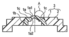
- FIG. 3 is an enlarged longitudinal sectional view showing a portion A of FIG.
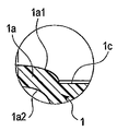
- FIG. 4 is a top view showing an optical element which is a primary molding part of the first embodiment.
- FIG. 5 is a longitudinal sectional view of the entire two-color molding die showing a state where the injection molding die according to the first embodiment is moved to the clamping position.
- FIG. 6 is a longitudinal sectional view showing a state where the primary mold of the injection mold according to the first embodiment is moved to the mold opening position.
- FIG. 1 is a top view of a two-color molded product which is a secondary molding portion according to the first embodiment of the present invention.
- 2 is a cross-sectional view taken along line II-II shown in FIG.
- FIG. 3 is an enlarged longitudinal sectional view showing
- FIG. 7 is a plan view of the movable mold of the primary mold of the injection mold according to the first embodiment.
- FIG. 8 is a longitudinal sectional view showing a state in which the primary mold of the injection mold according to the first embodiment has been moved to the clamping position.
- FIG. 9 is a longitudinal sectional view showing an enlarged state of the first cavity of the primary mold according to the first embodiment.
- FIG. 10 is a longitudinal sectional view showing a state where the secondary mold of the injection mold of the first embodiment is moved to the mold opening position.
- FIG. 11 is a plan view of the movable mold of the secondary mold of the injection mold according to the first embodiment.
- FIG. 12 is an enlarged longitudinal sectional view showing a portion B of FIG. FIG.
- FIG. 13 is a longitudinal sectional view showing a state where the secondary mold of the injection mold according to the first embodiment is moved to the mold clamping position.
- FIG. 14 is a longitudinal sectional view showing an enlarged state of the second cavity of the secondary mold according to the first embodiment.
- FIG. 15 is a longitudinal cross-sectional view showing the open state of the entire two-color mold after the molding of the first embodiment is completed.
- FIG. 16 is a side view showing the overall configuration of the endoscope according to the second embodiment of the present invention.
- FIG. 17 is a front view showing the distal end portion of the endoscope according to the second embodiment.
- 18 is a cross-sectional view taken along line XVIII-XVIII shown in FIG.
- FIG. 19 is a cross-sectional view taken along line XIX-XIX shown in FIG. 20 is a cross-sectional view taken along line XX-XX shown in FIG.
- FIG. 21 is a longitudinal sectional view showing an enlarged state of the second cavity of the secondary mold at the distal end portion of the endoscope according to the second embodiment.
- FIG. 22A shows a multicolor molded product according to the third embodiment of the present invention, and is a top view showing the multicolor molded product.
- 22B is a cross-sectional view taken along line XXIIB-XXIIB shown in FIG. 22A.
- FIG. 1 is a top view of a multicolor molded product, for example, a two-color molded product 3, which is a resin molded product of the present embodiment.
- 2 is a cross-sectional view taken along line II-II shown in FIG.
- FIG. 5 is a cross-sectional view of the entire two-color molding die (molding die) 50 for molding the two-color molded product 3.
- the two-color molded product 3 of the present embodiment is formed by integrating the optical element 1 and the cylindrical adjacent member 2 by two-color molding.
- the optical element 1 and the adjacent member 2 are an integrated object.
- the optical element 1 is an optical lens, for example, and is a primary molding part.
- the adjacent member 2 is a secondary molding portion that holds the optical element 1.
- the optical element 1 is a lens having, for example, a convex shape and a concave shape.
- the optical element 1 is formed of a transparent resin material that can transmit light.
- This resin material is a first resin (first molding resin).
- This resin material is, for example, PC (polycarbonate) and has meltability.
- the adjacent member 2 is disposed adjacent to the optical element 1.
- the adjacent member 2 is formed of a second resin (second molding resin) different from the first resin.
- the adjacent member 2 is formed by injection molding the second resin.
- the second resin is formed, for example, by coloring an opaque color on PC (polycarbonate).
- the optical element 1 has an optical element body 1a having two opposing surfaces (an outer surface and an inner surface), and a cylindrical cylindrical wall portion 1b connected to the outer peripheral portion of the optical element body 1a.
- the outer surface of the optical element body 1a is a convex optical functional surface 1a1 having a convex curved surface shape.
- the inner surface of the optical element body 1a shows a concave optical functional surface 1a2 having a concave curved surface shape.
- the adjacent member 2 is a lens frame used for positioning when the two-color molded product 3 is assembled to a component (not shown). This component (not shown) indicates, for example, an observation optical system of an endoscope or an imaging optical system of a camera.
- the adjacent member 2 is also an imaging lens unit, for example. In this case, the adjacent member 2 has a structure in which a lens obtained by other means is assembled to the inner diameter portion of the adjacent member 2.
- the two-color molded product 3 is two-color molded by a later-described two-color molding die 50 shown in FIG.
- an air vent transfer shape 1 c is formed on the outer surface of the optical element 1 other than the optical functional surface 1 a 1 during the secondary molding.
- the air vent transfer shape 1c is molded by pressing and holding a portion other than the optical functional surfaces 1a1 and 1a2 by a secondary molding die 20 described later.
- the two-color mold 50 of the present embodiment has a primary mold (first mold) 10 and a secondary mold (second mold) 20.
- the primary mold 10 and the secondary mold 20 are arranged on a movable platen 70 of an injection molding machine described later.
- the primary mold 10 includes a first fixed mold 100 and a movable mold 300.
- the first fixed mold 100 and the movable mold 300 are arranged to face each other with a PL (parting line) interposed therebetween.
- the movable mold 300 is arranged to be movable in the mold opening / closing direction with respect to the first fixed mold 100.
- the mold opening / closing direction indicates the vertical (Z) direction in FIG. That is, the movable mold 300 can be moved toward and away from the first fixed mold 100.
- the secondary mold 20 includes a second fixed mold 200 and a movable mold 300.
- the second fixed mold 200 and the movable mold 300 are arranged to face each other with the PL interposed therebetween.
- the movable mold 300 is arranged to be movable in the mold opening / closing direction with respect to the second fixed mold 200. That is, the movable mold 300 can be moved toward and away from the second fixed mold 200.
- the configuration of the fixed mold is different between the primary side and the secondary side, and the configuration of the movable mold is the same on the primary side and the secondary side.
- the name of the movable component is not distinguished between the primary and secondary components, and is hereinafter referred to as the movable mold 300.
- the primary molding die 10 primarily molds the optical element 1 that is a primary molding part.
- the secondary molding die 20 secondary molds the adjacent member 2.
- the optical element 1 and the adjacent member 2 are integrated. Thereby, the two-color molded product 3 is formed.
- the first fixed mold 100 includes a primary fixed side mounting plate 110, a primary fixed side dropping plate 120, and a primary fixed side mold plate 130.
- a primary fixed insert 101 is inserted into the central portion of the primary fixed side template 130.
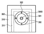
- the movable mold 300 includes a movable mold plate 310, a movable receiving plate 320, a spacer block 340, and a movable mounting plate 350. Inside the spacer block 340, an ejector plate 330 constituting a protruding mechanism is disposed. Four ejector pins 302 are attached to the ejector plate 330 (see FIG. 7).
- a movable insert 301 is fitted into the central portion of the movable side template 310. That is, the movable insert 301 is inserted into the movable mold 300.
- the movable insert 301 is connected to the primary fixed insert 101 in the Z-axis direction. It is arranged so as to face each other at a distance. That is, the movable nest 301 is arranged opposite to the primary fixed nest 101 and spaced apart.
- the second fixed mold 200 includes a secondary fixed side mounting plate 210, a secondary fixed side dropping plate 220, and a secondary fixed side mold plate 230.
- the secondary fixed side template 230 is a hollow disposed in the movable insert 301 of the movable side template 310, specifically, in a portion corresponding to the convex optical functional surface 1a1.
- the movable mold 300 facing the second fixed mold 200 has the same configuration as the movable mold 300 facing the first fixed mold 100 as described above.
- the movable side mounting plate 350 of the primary molding die 10 and the movable side mounting plate 350 of the secondary molding die 20 are fixed to the movable platen 70 of the same injection molding machine.
- the movable platen 70 is movable in the Z direction.
- the movable platen 70 is rotatable about the rotation shaft 60.
- the rotation shaft 60 is disposed in the center of the movable platen 70 and parallel to the Z direction.
- the primary fixed side mounting plate 110 of the primary molding die 10 and the secondary fixed side mounting plate 210 of the secondary molding die 20 are fixed to a fixed side platen of an injection molding machine (not shown).
- FIG. 6 shows a state where the primary mold 10 is opened.
- the primary fixed side template 130 of the primary mold 10 has a recess 130 a formed at the approximate center of the lower surface of the primary fixed side plate 130.
- the end surface of the recess 130 a is formed by the lower surface of the primary fixed insert 101.
- a primary fixed side molding surface 101A having a concave curved surface shape is formed on the lower surface of the primary fixed nest 101.
- a convex optical functional surface 1a1 having a convex curved surface shape shown in FIG. 2 is molded by the primary fixed side molding surface 101A of the concave curved surface shape.
- the primary fixed side template 130 is formed with a molding surface 130b for molding the outer surface shape of the cylindrical wall portion 1b shown in FIG.
- a movable side molding surface 301A having a convex curved surface is formed on the movable insert 301 facing the primary fixed side template 130. As shown in FIG. The movable side molding surface 301A is disposed so as to be separated from and opposed to the primary fixed side molding surface 101A. A concave optical functional surface 1a2 having a concave curved surface shape shown in FIG. 2 is molded by the movable side molding surface 301A.
- the first cavity 1000 is formed between the two. That is, the primary mold 10 defines a first cavity 1000 for molding the optical element 1.
- the first cavity 1000 is a primary molding cavity necessary for molding the optical element 1 which is a primary molding unit.
- the first cavity 1000 is formed to include a primary fixed-side molding surface 101A, a molding surface 130b, and a movable-side molding surface 301A. Specifically, the first cavity 1000 indicates a space surrounded by the primary fixed insert 101, the primary fixed side mold plate 130, the movable insert 301 and the movable side mold plate 310.
- the convex surface optical function surface 1a1 and the concave optical function surface 1a2 of the optical element 1 shown in FIG. 2 are formed by the primary fixed side molding surface 101A and the movable side molding surface 301A. Is done.
- the outer surface of the cylindrical wall portion 1b of the optical element 1 shown in FIG. 2 is formed by the molding surface 130b. In this way, the molding surface 130 b molds the outer surface shape of the optical element 1 of the first fixed mold 100.
- the primary fixed side mounting plate 110 and the primary fixed side dropping plate 120 have a primary sprue 11 for primary molding.
- the primary molding primary sprue 11 is disposed at the center of the primary fixed side mounting plate 110 and the center of the primary fixed side dropping plate 120.
- the primary molding primary sprue 11 supplies a resin material for molding the optical element 1 in the Z direction.
- the primary fixed side template 130 includes a primary molding runner 12 communicating with the primary molding primary sprue 11, a primary molding secondary sprue 13 communicating with the primary molding runner 12, and a primary molding.
- a primary molding pinpoint gate 14 that communicates with the secondary sprue 13 and supplies the resin to the first cavity 1000 in order to fill the resin into the first cavity 1000 is provided (FIGS. 6 and 8). And).
- the meltable resin material passes from the primary molding primary sprue 11 to the primary molding runner 12, the primary molding secondary sprue 13, and the primary molding pinpoint gate 14.
- the cavity 1000 is filled.
- the primary fixed side template 130 has a primary fixed side temperature regulator 131.
- a medium whose temperature is adjusted, such as water or oil, is always flowing through the primary fixed-side temperature controller 131 during primary molding. This medium prevents the resin material from solidifying.
- the movable template 310 is formed with a movable space 3000 that is a ring-shaped recess.
- the movable side space 3000 is disposed on the outer peripheral side of the movable insert 301 and on the side facing the PL. Furthermore, the movable side space 3000 is disposed around the central axis of the primary mold 10.
- the movable side space 3000 surrounds the movable nest 301.
- the movable side space 3000 forms a part of the second cavity 5000.
- the second cavity 5000 is a secondary molding cavity for the adjacent member 2 of the two-color molded product 3.
- four ejector pins 302 are arranged so as to be in contact with the bottom surface of the movable side space 3000 (see FIGS. 6 and 7).
- FIG. 10 shows a state where the secondary molding die 20 is opened.
- the secondary fixed side mold plate 230 of the second fixed mold 200 has a secondary fixed side space 2000 formed substantially at the center of the lower surface of the secondary fixed side mold plate 230. .
- the secondary fixed side space 2000 forms a part of the second cavity 5000 for molding the adjacent member 2.
- the secondary fixed side space 2000 is disposed around the central axis of the secondary mold 20 and has a circular recess.
- the secondary fixed side space 2000 is larger than the first circular concave portion 2000a having a large diameter arranged on the lower surface side of the secondary fixed side template 230, and the first circular concave portion 2000a.
- a second circular recess 2000b having a smaller diameter than the first circular recess 2000a.
- the secondary fixed side template 230 has a hollow secondary fixed space 201 disposed in a portion corresponding to the convex optical functional surface 1a1 of the optical element 1. And the secondary fixed press holding
- the secondary fixed press holding portion 201A has two air vents 201B.
- the air vent 201B communicates the air trap portion that is disposed at the boundary between the optical element 1 and the secondary fixed space 201 and is formed of the second resin, and the hollow secondary fixed space 201. This is a gap where the resin 2 cannot enter.
- the air vent 201B has an air venting or venting structure for venting air (air) remaining in the second cavity 5000 or gas generated from the raw material when the molten resin is injected into the second cavity 5000. It is a groove.
- the two air vents 201B of the present embodiment are formed as linear grooves.
- the air vent 201B is formed on the inner bottom portion of the second circular recess 2000b in the secondary fixed press holding portion 201A, and further extends in the radial direction of the second circular recess 2000b.
- the inner end of each air vent 201B is connected to the secondary fixed space 201, and the outer end of each air vent 201B is connected to the corner of the outer peripheral edge of the second circular recess 2000b. .
- the air vent 201B has a gap that does not flow (does not enter) the resin filled in the second cavity 5000, has a width of, for example, about 1 mm, and a depth of about 0.02 mm. Is formed. Note that the size of the air vent 201B actually affects the ultimate viscosity of the molded resin, the volatile substances of the material, and the like, and therefore is appropriately selected according to the type of resin such as the volume of the molded product and the flow length of the molded resin.
- the secondary fixed side mounting plate 210 and the secondary fixed side dropping plate 220 of the secondary molding die 20 have a primary sprue 21 for secondary molding.
- the secondary forming primary sprue 21 is disposed at the center of the secondary fixed side mounting plate 210 and the center of the secondary fixed side dropping plate 220.
- the secondary molding primary sprue 21 supplies a resin material for molding the adjacent member 2 in the Z direction.
- the secondary fixed-side template 230 includes one secondary molding runner 22 that communicates with the secondary molding primary sprue 21 and two secondary molding secondary sprues 23 that communicate with the secondary molding runner 22.
- the second cavity 5000 is formed by the secondary fixed side space 2000 and the movable side space 3000. That is, the secondary mold 20 defines the second cavity 5000 for molding the adjacent member 2 with the second resin different from the first resin.
- the two secondary sprue 23 for secondary molding and the two pinpoint gates 24 for secondary molding shown in FIG. 11 are arranged on both sides of the secondary fixed space 201.
- the line connecting the centers of the two secondary molding pinpoint gates 24 is arranged in a state substantially orthogonal to the line connecting the center lines of the two air vents 201B.
- the number of air vents 201B is not necessarily limited to two and may be one or more. It is preferable to provide the air vent 201B according to the number of secondary molding pinpoint gates 24.
- an optical element that is a primary molded portion between the second fixed mold 200 and the movable mold 300 in advance as shown in FIG. 1 is set.
- the optical element 1 is held in a state of being fitted to the movable insert 301 of the movable mold 300 of the primary mold 10.
- a second cavity 5000 as a secondary molding cavity is formed between the second fixed mold 200 and the movable mold 300.
- the second cavity 5000 communicates in a state where the secondary fixed side space 2000 of the second fixed mold 200 and the movable side space 3000 of the movable mold 300 are opposed to each other with the PL interposed therebetween.
- the second resin is filled in the second cavity 5000 as shown in FIG. Thereby, the adjacent member 2 is joined to the periphery of the optical element 1 which is a primary molding part, and the two-color molded product 3 is molded.
- the two-color mold 50 shown in FIG. 5 is used.
- the optical element 1 that is a primary molding portion is primarily molded by the primary molding die 10
- the adjacent member 2 that is the secondary molding portion is secondary molded by the secondary molding die 20.
- a transparent and molten first resin is supplied from the primary molding primary sprue 11 to the primary molding runner 12 by a resin injection unit (not shown). Subsequently, the first resin passes from the primary molding runner 12 through the primary molding secondary sprue 13 and the primary molding pinpoint gate 14, and is supplied and filled into the first cavity 1000.
- the first resin filled in the first cavity 1000 is maintained in a pressure-holding state for a predetermined time at a predetermined pressure.
- the optical element 1 which is a primary molding part is obtained by cooling 1st resin.
- the movable platen 70 of the molding machine rotates by 180 ° around the rotation shaft 60.
- the movable die 300 that fits and holds the optical element 1 that is the primary molding portion and the second fixed die 200 are arranged to face each other.
- the primary mold 10 the movable mold 300 in which the optical element 1 that is the primary molding portion is not disposed and the first fixed mold 100 are disposed to face each other. In this state, the two-color mold 50 is closed.
- the convex optical functional surface 1a1 is disposed in the secondary fixed space 201 of the second fixed mold 200. There is no contact with the fixed mold 200.
- the outer surface of the optical element 1 other than the convex optical function surface 1a1 is in close contact with the secondary fixed press holding portion 201A.
- the second cavity 5000 is filled with the colored second resin.
- the second resin is maintained in a pressure holding state at a predetermined pressure for a predetermined time.
- the adjacent member 2 which is a secondary molding part is obtained by cooling 2nd resin.
- the optical element 1 as the primary molding part and the adjacent member 2 as the secondary molding part are integrated, and accordingly, the two-color molded product 3 is molded.
- primary molding of the optical element 1 that is the primary molding portion described above is simultaneously performed in the primary mold 10.
- the movable mold 300 of the secondary mold 20 is opened as shown in FIG. At this time, the two-color molded product 3 is separated from the secondary molding secondary sprue 23 at the position of the secondary molding pinpoint gate 24. Thereafter, the ejector pin 302 is projected by the projecting mechanism of the molding machine, whereby the two-color molded product 3 held by the movable mold 300 of the secondary molding die 20 is taken out.
- the secondary molding die 20 When the secondary molding die 20 is opened, the primary molding die 10 is also opened at the same time, and the movable nest of the movable die 300 is formed in a state where the optical element 1 as the primary molding portion is molded by the movable die 300. 301 is fitted and held. Subsequently, the series of primary forming steps and secondary forming steps described above are repeated.
- the optical element 1 that is a primary molded portion is primarily molded with a transparent first resin. Thereafter, the transparent first resin is cooled and contracted, so that the optical element 1 as the primary molded portion is held in a fitted state by the movable insert 301 of the movable mold 300.
- the optical element 1 that is the primary molding part is released from the first fixed mold 100.
- the movable element 300 and the secondary fixed press holding portion 201 ⁇ / b> A of the second fixed mold 200 are used with the optical element 1 fitted and held by the movable insert 301.
- Optical elements 1 other than the convex optical functional surface 1a1 are pressed and held.
- the secondary fixed space 201 is disposed at a position corresponding to the convex optical functional surface 1 a 1, the convex optical functional surface 1 a 1 does not contact the wall surface of the second fixed mold 200. In this state, secondary molding of the two-color molded product 3 is performed.
- air is generated at the boundary between the optical element 1 and the adjacent member 2. This air is discharged to the secondary fixed space 201 through the air vent 201B. That is, the air is discharged out of the second cavity 5000.
- An air vent transfer shape 1c is formed on the outer surface of the optical element 1 to be bonded to the air vent 201B other than the convex optical functional surface 1a1 of the optical element 1.
- the second fixed mold 200 places the hollow secondary fixed space 201 at a position corresponding to the convex optical function surface 1a1 of the optical element 1.
- the secondary optical functional surface 1a1 is directly applied to the wall surface of the second fixed mold 200 by the secondary fixed space 201 during the secondary molding of the two-color molded product 3.
- the two-color mold 50 can prevent the convex optical functional surface 1a1 of the optical element 1 from being deformed due to irregularities in the shape of the second fixed mold 200 or the like. Therefore, the two-color molded product 3 provided with the highly accurate optical element 1 is obtained.
- the two-color mold 50 can prevent air from accumulating at the boundary between the optical element 1 and the adjacent member 2 in the two-color molded product 3. And the two-color mold 50 can prevent a dent from occurring on the outer surface of the bonding interface at the boundary. Thereby, the highly accurate two-color molded product 3 without the hollow by filling with secondary molding resin is obtained.
- the air vent 201B should just be comprised in the state which can discharge
- FIG. Therefore, the shape of the air vent 201B can be adjusted by considering only the fluidity (filling condition) of the second resin and configuring only the flow end portion (confluence position) or in the middle of the flow process.
- the optical element 1 can have a function corresponding to the convex curved surface by primary molding. Thus, the function can be changed as appropriate. In addition, it is not limited to this method, It can change into arbitrary methods as needed.
- FIG. 17, FIG. 18, FIG. 19, and FIG. 20 show a second embodiment of the present invention. This embodiment is applied to forming the distal end portion 406 of the endoscope 401.
- FIG. 16 shows an overall configuration of an endoscope 401 that observes the inside of a body cavity and performs diagnosis, treatment, and the like inside the body cavity.
- the endoscope 401 has an elongated and flexible insertion portion 405 that is inserted into a body cavity of a patient.
- the insertion portion 405 is connected to the operation portion 407 at the proximal end of the insertion portion 405.
- the insertion portion 405 includes an elongated flexible tube portion 405a, a curved portion 405b connected to the distal end of the flexible tube portion 405a, and a rigid distal end portion 406 connected to the distal end of the curved portion 405b.
- the distal end portion 406 is disposed at the distal end of the insertion portion 405.
- a plurality of bending pieces (not shown) are arranged in a line along the central axis direction (longitudinal axis direction) of the insertion portion 405 so that adjacent bending pieces rotate in the vertical direction. It is formed by pivotally attaching to a shaft member.
- the bending portion 405b bends only in two upper and lower directions.
- the bending portion 405b may be bent in four directions that can be bent not only vertically but also horizontally.
- the operation unit 407 includes a gripping unit 407a and a bending mechanism unit 407b.
- the operation unit 407 has an eyepiece (not shown) disposed at the end of the operation unit 407.
- the bending mechanism portion 407b has a lever-type bending operation knob 407b1.
- the bending portion 405b is forcibly bent only in the vertical direction when the bending operation knob 407b1 of the operation portion 407 rotates. As a result, the direction of the tip 406 changes.
- the grip portion 407a has a channel cap 407d.
- the side surface of the operation unit 407 is connected to one end of the universal cord 407e.
- the other end of the universal cord 407e has a scope connector (not shown).
- the endoscope 401 is connected to the light source device 402 and the signal processing device 403 via the scope connector.
- the signal processing device 403 is connected to the observation monitor 404.
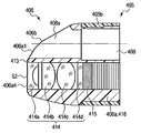
- the distal end portion 406 includes a single-part distal end portion main body (tip configuration portion) 406 a.
- the tip end body 406a is integrally molded with resin.
- the resin of the material forming the tip end body 406a is formed of an optically opaque material.
- the tip end body 406a is formed of, for example, a resin colored in black, for example, PSU (polysulfone).
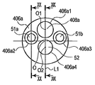
- the distal end surface of the distal end portion main body 406a has the distal ends of two illumination window portions 51a and 51b that emit illumination light, one observation window portion 52, and one treatment instrument insertion channel 408. And an opening 408a.
- the distal end opening 408a of the treatment instrument insertion channel 408 is disposed on the upper side with respect to the center position O of the distal end surface of the distal end portion main body 406a, and the observation is performed on the lower side.
- a window 52 is disposed.
- two illumination window portions 51a and 51b are arranged at symmetrical positions of a reference line L1 that connects between the center line O1 of the tip opening 408a and the center line O2 of the observation window portion 52, respectively.
- the outer peripheral surface on the upper surface side of the distal end body 406a (on the distal opening 408a side of the channel 408) is formed as a tapered inclined surface 406b from the proximal end side toward the distal end side.
- the distal end surface of the distal end portion main body 406a has a shape that is long horizontally and flat vertically.
- the distal end surface of the distal end main body 406a is formed, for example, as a substantially elliptical spatula having a short axis in the vertical direction and a long axis in the horizontal direction.
- the distal end main body 406a has a smooth surface from the outer peripheral edge of the distal end surface to the outer peripheral edge of the proximal end portion of the distal end main body 406a without a sharp angle or severe unevenness. Specifically, the entire distal end surface of the distal end portion main body 406a is formed by a continuous curved surface from the edge of the substantially elliptical distal end surface to the substantially circular outer peripheral surface of the latter half proximal end portion of the distal end portion main body 406a.
- the outer peripheral surface of the distal end portion body 406a extends from the outer peripheral edge of the substantially elliptical distal end surface to the curved portion 405b having a substantially circular cross section installed adjacent to the rear end of the distal end portion body 406a. It is a smooth curved surface that transitions from a substantially elliptical shape to a substantially circular shape.
- the inclined surface 406b on the upper surface side of the tip end body 406a is disposed in the direction in which the bending portion 405b is bent, in this case, the direction in which the tip end portion 406 rises.
- a rounded edge is formed at the peripheral edge of the distal end surface of the distal end portion main body 406a and the corner portion exposed to the outside of the distal end portion main body 406a.
- the distal end portion main body 406a has four holes (406a1 to 406a4) disposed inside the distal end portion main body 406a and disposed in parallel with the axial direction of the insertion portion 405. Yes.
- the first hole 406 a 1 is a channel hole formed as the tip opening 408 a of the channel 408.
- the second hole 406a2 and the third hole 406a3 are formed as a pair of left and right illumination housing holes in which an assembly member of the illumination optical system is installed.
- the fourth hole 406a4 is formed as an observation hole in which an assembly member of the observation optical system is installed.
- the inner end of the first hole 406a1 is connected to a channel tube (not shown) via a connection base.
- the proximal portion of the channel tube is guided to the operation unit 407 through the bending portion 405b and the flexible tube portion 405a, and is connected to the channel base 407d.
- a channel 408 penetrating from the channel cap 407d to the tip opening 408a is formed.
- the channel 408 is used for air supply / water supply and the like in addition to a treatment tool (not shown) being inserted.
- the fourth hole 406 a 4 has a first lens (or cover glass) 414 a that is disposed at the foremost position of the fourth hole 406 a 4 and forms the observation window portion 52.
- a second lens 414b, a third lens 414c, and a fourth lens 414d are sequentially arranged behind the first lens 414a.
- the lenses 414a, 414b, 414c, and 414d are formed as an observation optical system 414.
- the observation optical system 414 is fixed to the inner peripheral wall surface of the fourth hole 406a4 with, for example, an adhesive.
- An imaging element unit 415 having an imaging element such as a CCD is disposed at the imaging position of the observation optical system 414.
- the observation image formed by the observation optical system 414 is converted into an electric signal by the imaging element unit 415 and transmitted to the signal processing device 403 via a signal cable (not shown).
- the electrical signal (observation image) is converted into a video signal by the signal processing device 403 and output to the observation monitor 404.
- it may replace with the image pick-up element part 415, and the front-end
- the observation image formed by the observation optical system 414 is guided to the eyepiece through the image guide fiber and is observed by the eyepiece.
- the second hole 406a2 and the third hole 406a3 are disposed at the foremost positions of the holes 406a2 and 406a3, and have an illumination lens 412 that forms illumination window portions 51a and 51b.
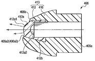
- a two-color molded product 413 is formed in which an illumination lens 412 that is an example of an optical member and a tip portion main body 406a are integrally formed.
- the tip end body 406 a is formed as a support member 416 that supports the illumination lens 412.
- the illumination lens 412 is a resin for optical components that is often used in the medical field, for example, and is an optically transparent resin such as PSU (polysulfone). Is formed.
- the support member 416 is formed of an optically opaque resin, for example, a black colored resin, such as PSU (polysulfone).
- the illumination lens 412 has a substantially circular lens body 412a and a cylindrical cylindrical wall portion 412b connected to the outer peripheral portion of the lens body 412a.
- the outer surface of the lens body 412a is an optical functional surface 412a1 having an inclined surface shape
- the inner surface of the lens body 412a is a concave optical function surface 412a2 having a concave curved surface shape.
- the inclined surface 406b on the upper surface side of the tip end main body 406a and the optical function surface 412a1 having the inclined surface shape are gently connected as the same surface without a step.
- the inclined surface 406b and the optical function surface 412a1 are gently connected as the same surface, so that no dirt enters the boundary portion.
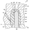
- the configuration of the primary mold is omitted, and here, the schematic configuration of the main part of the secondary mold 421 of the two-color molded product 413 will be described with reference to FIG.
- reference numeral 422 indicates a second fixed mold
- reference numeral 423 indicates a movable mold.
- the illumination lens 412 is a primary molding part.
- a second cavity 5001 which is a secondary molding cavity for the support member 416, is formed on the joint surface between the movable mold 423 and the second fixed mold 422.
- the support member 416 is an adjacent member of the illumination lens 412.
- the movable mold 423 has a movable insert 425 in the central portion of the movable side mold plate 424. After the primary molding, the illumination lens 412 that is the primary molding portion is fitted and held on the upper surface of the movable nest 425.
- the secondary fixed side template 426 of the second fixed mold 422 has a hollow secondary fixed space 427 at a portion corresponding to the inclined optical functional surface 412a1 of the illumination lens 412.
- the secondary fixed press holding portion 427A disposed on the secondary fixed side template 426 is in contact with the illumination lens 412 other than the optical function surface 412a1.
- Reference numeral 431 indicates a secondary molding sprue of the second fixed mold 422.
- the secondary fixed press holding portion 427A has two air vents 427B.
- the air vent 427B includes an air trap portion that is disposed at a boundary portion between the illumination lens 412 that is a primary molding portion and a support member 416 that is a secondary molding portion and is formed of a second resin, and a hollow secondary fixing.
- the gap communicates with the space 427 and the second resin cannot enter.
- the manufacturing method of the two-color molded product 413 is basically the same as that of the first embodiment, and will not be described.
- the two-color molded product 413 is configured by the illumination lens 412 and the support member 416 at the distal end portion 406 of the endoscope 401, and the outer surface of the two-color molded product 413 is smooth without any depression. Molded as a surface. As a result, cleaning at the time of reuse becomes easy, and inexpensive and hygienic endoscopic treatment becomes possible.
- the illumination lens 412 as the primary molding portion is fitted and held in the movable insert 425, and the outer peripheral portion of the illumination lens 412 other than the optical function surface 412a1 is movable. 423 and the secondary fixed press holding portion 427A are pressed and held.
- the secondary fixed space 427 is disposed at a position corresponding to the optical function surface 412a1, the optical function surface 412a1 does not contact the inner wall surface of the second fixed mold 422, and the two-color molded product 413 is Secondary forming is performed.
- the air in the secondary molding cavity is not compressed by the injection pressure of the molten resin, and the illumination lens 412 and the injection resin itself are not altered by the compression heat. Therefore, a two-color molded product 413 is obtained in which the chemical resistance performance and adhesion strength between the illumination lens 412 and the support member 416 are not deteriorated. Therefore, it is possible to provide a safe endoscope 401 that is not eroded by chemical cleaning at the time of reuse and has sufficient adhesion strength.
- the present invention is not limited to the above embodiment.
- application examples applied to the two-color molded product 3 shown in FIG. 2 and the two-color molded product 413 shown in FIG. 20 are shown as multicolor molded products. Is not to be done.
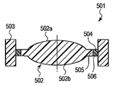
- the present invention may be applied to a three-color molded product 501 as a multicolor molded product or a multicolor molded product of four or more colors although not shown. .
- the three-color molded product 501 of the present embodiment includes, for example, an optical element (first molding part) 502 that is an optical lens, and a cylindrical colored outer peripheral part (second molding part) that is a lens frame that holds the optical element 502. ) 503, and a ring-shaped intermediate layer (third molding portion) 504 disposed between the optical element 502 and the colored outer peripheral portion 503 is formed by an integral body by multicolor molding.
- the optical element 502 is formed by injection molding a first resin, which is a light transmissive resin material.
- the colored outer peripheral portion 503 is disposed away from the optical element 502, and is formed by injection molding a second resin different from the first resin.
- the intermediate layer 504 is disposed between the optical element 502 and the colored outer peripheral portion 503, and a third resin different from the first resin and the second resin is used as the optical element 502 and the colored outer peripheral portion 503. It is formed by injection molding.
- a first thermal fusion bonding portion 505 is formed at the bonding interface between the optical element 502 and the intermediate layer 504 and bonded in a state of being melted and mixed.
- a second hot-melt joint portion 506 is formed at the joint interface between the intermediate layer 504 and the colored outer peripheral portion 503 and is joined in the state of being thermally melted and mixed.
- the optical element 502 has two surfaces facing each other, and these two surfaces function as optical function surfaces 502a and 502b, respectively.
- the optical element 502 has a convex-shaped first optical functional surface 502a on the upper side and a convex-curved second optical functional surface 502b on the lower side.
- the colored outer peripheral portion 503 functions as positioning in the lens barrel when the three-color molded product 501 is attached to a lens barrel (not shown).
- the movable mold of the three-color molded product 501 has a movable insert at the center of the movable mold plate. Then, after the primary molding, the optical element 502 as the primary molding part is fitted and held on the upper surface of the movable nest.
- the secondary fixed side mold plate of the second fixed mold of the secondary mold has a hollow secondary fixed space corresponding to the first optical function surface 502a. Then, the secondary fixed press holding portion comes into contact with the optical element 502 other than the first optical function surface 502a.
- the second fixed type secondary fixed press holding portion has two air vents.
- the air vent includes an air trap portion that is disposed at a boundary portion between the optical element 502 that is a primary molding portion and an intermediate layer 504 that is a tertiary molding portion and is formed of a third resin, and a hollow secondary fixing space.
- the gap communicates with the portion and the second resin cannot enter.
- the air vent is provided at the boundary between the colored outer peripheral portion 503 that is a secondary molded portion and the intermediate layer 504 that is a tertiary molded portion, and an air trap portion formed by a third resin, and a hollow secondary shape. The gap communicates with the portion of the fixed space, and the second resin cannot enter.
- the three-color molded product 501 of the present embodiment is molded by the same manufacturing method as in the above embodiments. Then, at the time of secondary molding by the secondary molding die, the optical element 502 which is a primary molding portion is fitted and held in a movable movable insert. In this state, the outer peripheral portion of the optical element 502 other than the first optical function surface 502a is pressed and held by the movable type and the second fixed type secondary fixed pressing holding unit. At this time, the second fixed type secondary fixed space is disposed at a position corresponding to the first optical function surface 502a. Therefore, the secondary molding of the three-color molded product 501 is performed without the first optical functional surface 502a coming into contact with the wall surface of the second fixed mold.
- air is generated at the boundary between the optical element 502 and the intermediate layer 504 and at the boundary between the intermediate layer 504 and the colored outer peripheral portion 503. Air is discharged to the secondary fixed space through two air vents. At this time, an air vent transfer shape is formed on the outer surface of the optical element 502 other than the first optical functional surface 502a and on the outer surface of the optical element 502 joined to the air vent.
- the air in the secondary molding cavity is not compressed by the injection pressure of the molten resin, and the optical element 502 and the injection resin itself are not altered by the compression heat. Therefore, a three-color molded product 501 is obtained in which chemical resistance performance and adhesion strength between the optical element 502 and the colored outer peripheral portion 503 are not deteriorated. Therefore, it is possible to provide a safe endoscope that is not eroded by chemical cleaning during reuse and has sufficient adhesion strength.
- Movable mold A first cavity that has a first fixed-side runner through which the first resin passes and that is formed of the first resin and that has an optical functional surface is formed between the movable-side mold and the first cavity.
- a first fixed mold to be defined;
- a second cavity defining a second cavity for molding the secondary molded portion with a second resin different from the first resin with respect to the molded optical element is defined between the movable side mold and the second cavity.
- a fixed mold Have A two-color molding mold for molding a two-color molded product with the movable mold, the first fixed mold and the second fixed mold,
- the second fixed mold is a two-color molding mold that has a hollow shape and abuts only on the optical element other than the optical functional surface.
- a molding method of a two-color molded product for molding a two-color molded product comprising:
- the second stationary mold has an air vent;
- the method for molding a two-color molded product according to additional item 3 wherein the secondary molding step discharges the gas generated during the secondary molding out of the second cavity by the air vent.
- the present invention is effective in a technical field using a multi-color molding product, a molding method for a multi-color molding product, a molding method for a multi-color molding product, a multi-color molding product, and a technical field for manufacturing the same. .
- the present invention is not limited to the above-described embodiment as it is, and can be embodied by modifying the constituent elements without departing from the scope of the invention in the implementation stage. Further, various inventions can be formed by appropriately combining a plurality of constituent elements disclosed in the embodiment.
Landscapes
- Physics & Mathematics (AREA)
- Engineering & Computer Science (AREA)
- Manufacturing & Machinery (AREA)
- Mechanical Engineering (AREA)
- General Physics & Mathematics (AREA)
- Optics & Photonics (AREA)
- Health & Medical Sciences (AREA)
- Ophthalmology & Optometry (AREA)
- Astronomy & Astrophysics (AREA)
- Injection Moulding Of Plastics Or The Like (AREA)
- Moulds For Moulding Plastics Or The Like (AREA)
- Instruments For Viewing The Inside Of Hollow Bodies (AREA)
Abstract
多色成形用成形型(50)において、第2の固定型(200,421)は、光学機能面(1a1,1a2,412a1,412a2,502a,502b)と対応する部分に配設されている中空形状部(201,427)を有する。第2の固定型(200,421)は、光学機能面(1a1,1a2,412a1,412a2,502,502b)以外の前記光学素子(1,412,502)にのみ当接する当接部(201A,427A)をさらに有する。
Description
本発明は、複数の異なる樹脂を組合せて一体化する多色成形用成形型と多色成形品の成形方法と多色成形品とに関する。
一般に、二色成形は、以下の技術を示す。2種類の異なる樹脂材料が用いられて、光学素子と、光学素子の枠部材などの隣接部材とが成形され、光学素子と隣接部材とが一体化する。例えば特許文献1は、この二色成形の一例を開示している。特許文献1において、光学部材を一次成形する一次成形型と、隣接部材を二次成形する二次成形型とが配設されている。なお、一次成形型の可動型と、二次成形型の可動型とは、共通に使用される。そして、光学部材は、一次成形型の第1の固定型と可動型との間に構成されるキャビティ内で一次成形される。次に第1の固定型と可動型とは、型開きされる。このとき光学素子の光学機能面は可動型に嵌合されたままとなっており、光学素子は可動型に保持されている。次に二次成形において、この光学素子を保持する可動型は、二次成形型の第2の固定型と組合わされる。そして隣接部材は、二次成形型の第2の固定型と可動型との間で二次成形される。このように特許文献1は、光学素子と隣接部材との二色成形品を得る方法を開示している。
また、特許文献2は、以下の内容を開示している。第1の成形部は、一次成形にて成形される。二次成形において、二次成形用キャビティは、第1の成形部と二次成形型部材とによって構成される。二次成形用の溶融樹脂は、二次成形用キャビティへ充填される。このとき第1の成形部の表面は、溶融樹脂の熱によって溶融する。そして二色成形品の成形時に、第1の成形部と二次成形型部材との結合界面部分とは、互いに結合する。
特許文献1において、光学機能面は、二次成形の際に、第2の固定型に接触する。このとき、第1の固定型の形状と第2の固定型の形状とは、必ずしも同一形状とは限らない。このため、第1の固定型によって成形された光学機能面の形状は、二次成形の際に第2の固定型によって変形する可能性がある。
また特許文献2において、エアートラップ部分が、第1の成形部と二次成形型部材との境界部における結合界面の外表面に発生する可能性がある。エアートラップ部分は、二次成形用の第2の樹脂内のエアー溜りを示す。この場合、溶融樹脂はエアートラップ部分に完全に充填されず、窪みが外表面に発生してしまう可能性がある。
本発明は、これらの事情に鑑みてなされたものであり、一次成形部である光学素子の光学機能面が二次成形に用いられる第2の固定型によって変形することを防止でき、かつ一次成形によって成形された第1の成形部と、二次成形型部材との結合界面の外表面に窪みが発生することを防止できる多色成形用成形型と、多色成形用成形型によって成形される多色成形品の成形方法と、この成形方法を用いて成形される多色成形品を提供することにある。
本発明の多色成形用成形型の一態様は、第1の樹脂が通る第1の固定側ランナーを備えた第1の固定型と、前記第1の固定型に対して接離可能な可動型との間に、前記第1の樹脂によって形成され少なくとも光学機能面を有する光学素子である一次成形部を成形する第1のキャビティを規定する第1の成形型と、前記第1の成形型で成形された前記光学素子に対して接合させた状態で、前記第1の樹脂とは異なる第2の樹脂によって二次成形部を成形する第2のキャビティを規定する第2の成形型とを有し、前記第2の成形型は、前記可動型に対して接離可能な第2の固定型を有し、前記可動型と前記第2の固定型との間に前記第2のキャビティを規定することにより多色成形品を成形する多色成形用成形型であって、前記第2の固定型は、前記光学機能面と対応する部分に配設されている中空形状部と、前記光学機能面以外の前記光学素子にのみ当接する当接部とを有する。
本発明の多色成形品の成形方法の一態様は、可動型と第1の固定型との間に規定される第1のキャビティにおいて、光学機能面を有する光学素子である一次成形部を一次成形する一次成形ステップと、前記可動型の移動にともなって、前記第1のキャビティから前記光学素子を、前記可動型と、前記光学機能面以外の前記光学素子にのみ当接する中空形状の第2の固定型との間に規定される第2のキャビティへ移動させる可動型の移動ステップと、前記第2のキャビティで二次成形部を二次成形し、移動後の前記光学素子に対して前記二次成形部を一体化させる二次成形ステップと、を具備する。
本発明の一態様は、上記に記載の多色成形品の成形方法を用いて成形された多色成形品を提供する。
本発明によれば、一次成形部である光学素子の光学機能面が二次成形に用いられる第2の固定型によって変形することを防止でき、かつ一次成形によって成形された第1の成形部と、二次成形型部材との結合界面の外表面に窪みが発生することを防止できる多色成形用成形型と、多色成形用成形型によって成形される多色成形品の成形方法と、この成形方法を用いて成形される多色成形品を提供することができる。
[第1の実施の形態]
(構成)
図1乃至図15は、本発明の第1の実施の形態を示す。図1は、本実施の形態の樹脂成形品である多色成形品、たとえば二色成形品3の上面図である。図2は、図1に示すII-II線における断面図である。また、図5は、二色成形品3を成型する二色成形型(成形型)50全体の断面図である。
(構成)
図1乃至図15は、本発明の第1の実施の形態を示す。図1は、本実施の形態の樹脂成形品である多色成形品、たとえば二色成形品3の上面図である。図2は、図1に示すII-II線における断面図である。また、図5は、二色成形品3を成型する二色成形型(成形型)50全体の断面図である。
図1および図2に示すように、本実施の形態の二色成形品3は、光学素子1と円筒状の隣接部材2とが二色成形によって一体化することで、形成される。光学素子1と隣接部材2とは、一体物である。光学素子1は、例えば光学レンズであり、一次成形部である。隣接部材2は、光学素子1を保持する二次成形部である。光学素子1は、例えば凸形状と凹形状とを有するレンズである。この光学素子1は、光が透過可能な透明な樹脂材料によって形成される。この樹脂材料は、第1の樹脂(第1成形樹脂)である。この樹脂材料は、例えばPC(ポリカーボネート)などであり、溶融性を有している。隣接部材2は、光学素子1に隣接して配置される。隣接部材2は、第1の樹脂とは異なる第2の樹脂(第2成形樹脂)によって形成される。第2の樹脂が射出成形されることで、隣接部材2は形成される。第2の樹脂は、本実施の形態では、例えばPC(ポリカーボネート)に不透明な色が着色されることで形成されている。
図2に示すように光学素子1は、向かい合う2面(外面と内面)を有する光学素子本体1aと、この光学素子本体1aの外周部位と連結されている円筒形状の筒壁部1bとを有する。光学素子本体1aの外面は、凸曲面形状の凸面光学機能面1a1を示す。光学素子本体1aの内面は、凹曲面形状の凹面光学機能面1a2を示す。隣接部材2は、二色成形品3が図示しない部品に組付けられる際、位置決めに用いられるレンズ枠である。この図示しない部品は、例えば、内視鏡の観察光学系、またはカメラの撮像光学系などを示す。隣接部材2は、例えば撮像レンズユニットでもある。この場合、隣接部材2は、隣接部材2の内径部分に、他手段によって得られたレンズが組付ける構造を有している。
本実施の形態では、二色成形品3は、図5に示す後述する二色成形型50によって二色成形される。このとき、図1と図2と図3と図4とに示すように、エアーベント転写形状1cが光学機能面1a1以外の光学素子1の外表面に二次成形時に形成される。このエアーベント転写形状1cは、光学機能面1a1,1a2以外の部分が後述する二次成形型20によって押圧保持されることで、成形される。
次に、図5を参照して二色成形型50の構成を説明する。本実施の形態の二色成形型50は、一次成形型(第1の成形型)10と二次成形型(第2の成形型)20とを有している。一次成形型10と二次成形型20とは、後述する射出成形機の可動プラテン70上に配置されている。
一次成形型10は、第1の固定型100と可動型300とを有している。第1の固定型100と可動型300とは、PL(パーティングライン)を挟んで互いに対向して配置されている。可動型300は、第1の固定型100に対し型開閉方向に移動可能に配置されている。型開閉方向は、図5において上下(Z)方向を示す。つまり可動型300は、第1の固定型100に対し接離可能である。また、二次成形型20は、第2の固定型200と可動型300とを有している。第2の固定型200と可動型300とは、PLを挟んで互いに対向して配置されている。可動型300は、第2の固定型200に対し型開閉方向に移動可能に配置されている。つまり可動型300は、第2の固定型200に対し接離可能である。
これら一次成形型10と二次成形型20とにおいて、固定型の構成は一次側と二次側で異なり、可動型の構成は一次側と二次側とで同一である。このため、ここでは可動型の構成部品の呼称は一次用と二次用とで区別せずに以下、可動型300とする。
二色成形品3が成形される際、一次成形型10は、一次成形部である光学素子1を一次成形する。次に、二次成形型20は、隣接部材2を二次成形する。隣接部材2が二次成形されると同時に、光学素子1と隣接部材2とが一体化する。これにより二色成形品3が形成される。
図6に示すように第1の固定型100は、一次固定側取付板110と一次固定側落下板120と一次固定側型板130とを有する。一次固定側型板130の中央部分には一次固定入子101が嵌挿されている。
図6に示すように可動型300は、可動側型板310と可動側受板320とスペーサーブロック340と可動側取付板350とを有する。スペーサーブロック340の内側には、突出し機構を構成するエジェクタープレート330が配設されている。このエジェクタープレート330には、4本のエジェクターピン302が取付けられている(図7参照)。可動側型板310の中央部分には、可動入子301が嵌挿されている。即ち、可動入子301は、可動型300内に挿入されている。可動入子301は、一次成形型10の第1の固定型100と一次成形型10の可動型300とが型締めされる時(図8参照)に、Z軸方向において一次固定入子101と距離を開けて対向するように配置されている。つまり可動入子301は、一次固定入子101と対向し離間して配設されている。
図10に示すように第2の固定型200は、二次固定側取付板210と二次固定側落下板220と二次固定側型板230とを有する。図10と図11とに示すように、二次固定側型板230は、可動側型板310の可動入子301、詳細には凸面光学機能面1a1と対応する部分に配設されている中空形状の二次固定空間201と、二次固定空間201の外周に配設され、凸面光学機能面1a1以外の光学素子1にのみ当接する二次固定押圧保持部201Aとを有している。この第2の固定型200に対向する可動型300は、前述の通り第1の固定型100に対向する可動型300と同じ構成である。
図5に示すようにこれら一次成形型10の可動側取付板350と二次成形型20の可動側取付板350とは、同一の射出成形機の可動プラテン70に固定されている。この可動プラテン70は、Z方向に可動する。可動プラテン70は、回転軸60を中心として回転可能となっている。回転軸60は、可動プラテン70の中央位置且つZ方向に対して平行に配設されている。さらに、一次成形型10の一次固定側取付板110と、二次成形型20の二次固定側取付板210とは、図示しないが射出成形機の固定側プラテンに固定されている。
次に、一次成形型10の詳細構造を記す。図6は、一次成形型10が型開きされた状態を示す。図6に示すように一次成形型10の一次固定側型板130は、一次固定側型板130の下面の略中央に形成されている凹部130aを有している。図9に示すように、この凹部130aの端面は、一次固定入子101の下面によって形成されている。この一次固定入子101の下面には、凹曲面形状の一次固定側成形面101Aが形成されている。この凹曲面形状の一次固定側成形面101Aにより、図2に示す凸曲面形状の凸面光学機能面1a1が成形される。さらに図9に示すように、一次固定側型板130には、図2に示す筒壁部1bの外側面形状を成形する成形面130bが形成されている。
図9に示すように、一次固定側型板130に対向する可動入子301には、凸曲面形状の可動側成形面301Aが形成されている。可動側成形面301Aは、一次固定側成形面101Aと離間してかつ対向するように配設されている。この可動側成形面301Aにより、図2に示す凹曲面形状の凹面光学機能面1a2が成形される。
そして、一次成形型10の第1の固定型100と一次成形型10の可動型300との型締め時(図8と図9とを参照)には、第1の固定型100と可動型300との間に、第1のキャビティ1000が構成される。つまり一次成形型10は、光学素子1を成形する第1のキャビティ1000を規定する。第1のキャビティ1000は、一次成形部である光学素子1の成形に必要な一次成形キャビティである。第1のキャビティ1000は、一次固定側成形面101Aと、成形面130bと、可動側成形面301Aとを含むように形成されている。詳細には、第1のキャビティ1000は、一次固定入子101と一次固定側型板130と可動入子301と可動側型板310とによって囲まれる空間部を示す。そして一次成形部である光学素子1の成形時には、一次固定側成形面101Aと可動側成形面301Aとによって、図2に示す光学素子1の凸面光学機能面1a1と凹面光学機能面1a2とが形成される。同時に成形面130bによって、図2に示す光学素子1の筒壁部1bの外側面が形成される。このように成形面130bは、第1の固定型100の光学素子1の外側面形状を成形する。
また図8に示すように、一次固定側取付板110および一次固定側落下板120は、一次成形用一次スプルー11を有している。一次成形用一次スプルー11は、一次固定側取付板110の中央と一次固定側落下板120の中央とに配設されている。一次成形用一次スプルー11は、光学素子1を成形する樹脂材料をZ方向に供給する。さらに、一次固定側型板130は、一次成形用一次スプルー11と連通している一次成形用ランナー12と、一次成形用ランナー12と連通している一次成形用二次スプルー13と、一次成形用二次スプルー13と連通し、第1のキャビティ1000に樹脂を充填するために、第1のキャビティ1000に樹脂を供給する一次成形用ピンポイントゲート14とを有している(図6と図8とを参照)。
そして、光学素子1の成形時には、溶融性を有する樹脂材料が一次成形用一次スプルー11から一次成形用ランナー12と一次成形用二次スプルー13と一次成形用ピンポイントゲート14とを経て第1のキャビティ1000内に充填される。
また図6に示すように、一次固定側型板130は、一次固定側温調菅131を有している。この一次固定側温調菅131には、一次成形時に例えば水や油などの温度調整された媒体が常時流れている。この媒体は、樹脂材料が固化することを防止する。
可動側型板310には、リング状の凹部である可動側空間3000が形成されている。可動側空間3000は、可動入子301の外周部側且つPLに面する側に配設されている。さらに可動側空間3000は、一次成形型10の中心軸を中心に配設されている。可動側空間3000は、可動入子301を囲う。図5に示すように、可動側空間3000は、第2のキャビティ5000の一部を形成する。第2のキャビティ5000は、二色成形品3の隣接部材2のための二次成形用キャビティである。そして、この可動側空間3000の底面に接するように4本のエジェクターピン302が配置される(図6と図7と参照)。
次に、二次成形型20の詳細構造について記す。図10は、二次成形型20が型開きされた状態を示す。図10に示すように第2の固定型200の二次固定側型板230は、二次固定側型板230の下面の略中央に形成されている二次固定側空間2000を有している。二次固定側空間2000は、隣接部材2を成形する第2のキャビティ5000の一部を形成する。この二次固定側空間2000は、二次成形型20の中心軸を中心に配設され、円形凹部を有している。さらに、図14に示すように二次固定側空間2000は、二次固定側型板230の下面側に配置された大径な第1の円形凹部2000aと、この第1の円形凹部2000aよりも上側に配置され、第1の円形凹部2000aよりも小径な第2の円形凹部2000bとを含む。
また、二次固定側型板230は、光学素子1の凸面光学機能面1a1と対応する部分に配設されている中空形状の二次固定空間201を有している。そして、二次固定押圧保持部201Aは、凸面光学機能面1a1以外の光学素子1と当接する。
さらに図11と図12とに示すように、二次固定押圧保持部201Aは、2つのエアーベント201Bを有する。エアーベント201Bは、光学素子1と二次固定空間201との境界部に配設され第2の樹脂によって形成されるエアートラップ部分と、中空形状の二次固定空間201とを連通し、かつ第2の樹脂が浸入不能な隙間である。エアーベント201Bは、第2のキャビティ5000内に溶融樹脂が射出された際、第2のキャビティ5000内に残留するエアー(空気)や原材料から発生したガスを抜くためのエアー抜きやガス抜き構造の溝部である。
図11に示すように本実施の形態の2つのエアーベント201Bは、直線状の溝部として形成されている。エアーベント201Bは、二次固定押圧保持部201Aにおける第2の円形凹部2000bの内底部に形成され、さらに第2の円形凹部2000bの半径方向に延設されている。図11に示すように各エアーベント201Bの内端部は二次固定空間201に連結され、各エアーベント201Bの外端部は第2の円形凹部2000bの外周縁の角部に連結されている。さらに、上記エアーベント201Bは、第2のキャビティ5000に充填された樹脂が流れない(浸入しない)大きさの隙間を有し、例えば1mm程度の幅を有し、深さ0.02mm程度の大きさに形成されている。なお、エアーベント201Bの大きさは、実際には成形樹脂の到達粘度、材料の揮発物質等に影響するため、成形品の体積、成形樹脂流動長等の樹脂の種類に応じて適宜、選択的に設定される。
また図10に示すように、二次成形型20の二次固定側取付板210と二次固定側落下板220とは、二次成形用一次スプルー21を有している。二次成形用一次スプルー21は、二次固定側取付板210の中央と二次固定側落下板220の中央とに配設されている。二次成形用一次スプルー21は、隣接部材2を成形する樹脂材料をZ方向に供給する。さらに、二次固定側型板230は、二次成形用一次スプルー21と連通する1つの二次成形用ランナー22と、二次成形用ランナー22と連通する2つの二次成形用二次スプルー23と、二次成形用二次スプルー23と連通し、第2のキャビティ5000に樹脂を充填するために、第2のキャビティ5000に樹脂を供給する2つの二次成形用ピンポイントゲート24とを有している。第2のキャビティ5000は、二次固定側空間2000および可動側空間3000によって形成される。つまり二次成形型20は、第1の樹脂とは異なる第2の樹脂によって隣接部材2を成形する第2のキャビティ5000を規定する。ここで、2つの二次成形用二次スプルー23と、図11に示す2つの二次成形用ピンポイントゲート24とは、二次固定空間201の両側に配置されている。図11に示すように、2つの二次成形用ピンポイントゲート24の中心間を結ぶ線は、2つのエアーベント201Bの中心線間を結ぶ線とほぼ直交する状態に配置されている。なお、エアーベント201Bの数は、必ずしも2つに限定されるものではなく、1または複数であってもよい。二次成形用ピンポイントゲート24の数に合わせてエアーベント201Bを設けることが好ましい。
二次成形型20の第2の固定型200と可動型300との型締め時には、図13に示すように予め第2の固定型200と可動型300との間に一次成形部である光学素子1がセットされる。このとき、光学素子1は、一次成形型10の可動型300の可動入子301に嵌合された状態で保持されている。そして、図5および図13に示すように第2の固定型200と可動型300との間には、二次成形用キャビティである第2のキャビティ5000が形成される。このとき、第2のキャビティ5000は、第2の固定型200の二次固定側空間2000と、可動型300の可動側空間3000とがPLを挟んで対向配置された状態で連通することで、形成される。この状態で、図14に示すように第2のキャビティ5000に第2の樹脂が充填される。これにより隣接部材2が一次成形部である光学素子1の周囲に接合され、二色成形品3が成形される。
次に、二色成形品3の製造方法について説明する。
本実施の形態の樹脂成形品である二色成形品3が製造される時、図5に示す二色成形型50が使用される。この二色成形型50では、一次成形型10で一次成形部である光学素子1が一次成形され、同時に二次成形型20で二次成形部である隣接部材2が二次成形される。
本実施の形態の樹脂成形品である二色成形品3が製造される時、図5に示す二色成形型50が使用される。この二色成形型50では、一次成形型10で一次成形部である光学素子1が一次成形され、同時に二次成形型20で二次成形部である隣接部材2が二次成形される。
[一次成形ステップ]
一次成形型10によって光学素子1が成形される時には、まず図5に示すように第1の固定型100および第2の固定型200に対し、接近させる方向に可動型300が移動して、型締めが行なわれる。このとき、一次成形型10では、図8に示すように第1の固定型100と可動型300とが接合された状態で型締めされる。これにより第1のキャビティ1000が形成される。
一次成形型10によって光学素子1が成形される時には、まず図5に示すように第1の固定型100および第2の固定型200に対し、接近させる方向に可動型300が移動して、型締めが行なわれる。このとき、一次成形型10では、図8に示すように第1の固定型100と可動型300とが接合された状態で型締めされる。これにより第1のキャビティ1000が形成される。
その後、図示しない樹脂射出ユニットによって、透明で溶融した第1の樹脂が一次成形用一次スプルー11から一次成形用ランナー12に供給される。続いて、第1の樹脂は、一次成形用ランナー12から一次成形用二次スプルー13と一次成形用ピンポイントゲート14とを通過し、第1のキャビティ1000内に供給され、充填される。
次いで、第1のキャビティ1000内で充填された第1の樹脂は、所定の圧力で所定の時間だけ保圧状態を維持される。次に第1の樹脂が冷却されることで、一次成形部である光学素子1が得られる。
[移動ステップ]
その後、図15に示すように第1の固定型100および第2の固定型200に対し、離れる方向に可動型300が移動し、型開きが行なわれる。このとき、図15に示すように光学素子1は、第1の樹脂が冷却され及び収縮することにより、可動型300の可動入子301に嵌合保持される。型開きが行なわれると同時に、光学素子1は、一次成形用二次スプルー13から一次成形用ピンポイントゲート14の位置で切り離される。
その後、図15に示すように第1の固定型100および第2の固定型200に対し、離れる方向に可動型300が移動し、型開きが行なわれる。このとき、図15に示すように光学素子1は、第1の樹脂が冷却され及び収縮することにより、可動型300の可動入子301に嵌合保持される。型開きが行なわれると同時に、光学素子1は、一次成形用二次スプルー13から一次成形用ピンポイントゲート14の位置で切り離される。
次に、光学素子1は可動入子301によって嵌合保持された状態で、回転軸60を中心として成形機の可動プラテン70は180°回転する。これにより図5に示すように、二次成形型20では、一次成形部である光学素子1を嵌合保持した可動型300と第2の固定型200とが対向して配置される。同時に、一次成形型10では、一次成形部である光学素子1が配設されていない可動型300と、第1の固定型100とが対向して配置される。この状態で二色成形型50が閉じられる。
このとき、図14に示すように可動入子301によって保持された光学素子1において、凸面光学機能面1a1は、第2の固定型200の二次固定空間201に配設されるため、第2の固定型200に接触することは無い。また凸面光学機能面1a1以外の光学素子1の外面は、二次固定押圧保持部201Aに密着する。
[二次成形ステップ]
続いて、図13に示すように第2のキャビティ5000に、着色された第2の樹脂が充填される。この第2の樹脂は、所定の圧力で所定の時間だけ保圧状態を維持される。次に、第2の樹脂が冷却されることで、二次成形部である隣接部材2が得られる。同時に一次成形部である光学素子1と二次成形部である隣接部材2とが一体化し、これに伴い二色成形品3が成形される。なお、この二次成形型20による二次成形時には、一次成形型10では上述した一次成形部である光学素子1の一次成形が同時に行なわれている。
続いて、図13に示すように第2のキャビティ5000に、着色された第2の樹脂が充填される。この第2の樹脂は、所定の圧力で所定の時間だけ保圧状態を維持される。次に、第2の樹脂が冷却されることで、二次成形部である隣接部材2が得られる。同時に一次成形部である光学素子1と二次成形部である隣接部材2とが一体化し、これに伴い二色成形品3が成形される。なお、この二次成形型20による二次成形時には、一次成形型10では上述した一次成形部である光学素子1の一次成形が同時に行なわれている。
二色成形品3が成形された後、図15に示すように二次成形型20の可動型300が開く。このとき、二色成形品3は、二次成形用ピンポイントゲート24の位置にて二次成形用二次スプルー23から切り離される。その後、エジェクターピン302が成形機の突出し機構により突出することで、二次成形型20の可動型300に保持されている二色成形品3は取り出される。
なお、この二次成形型20の型開き時には、一次成形型10でも同時に型開きが行なわれ、一次成形部である光学素子1が可動型300によって成形された状態で可動型300の可動入子301に嵌合保持されている。続いて、上述した一連の一次成形工程と二次成形工程とが繰り返される。
(作用)
次に、上記構成の作用について説明する。本実施の形態の二色成形型50が使用される時には、まず、本実施の形態では、透明な第1の樹脂により一次成形部である光学素子1が一次成形される。この後、透明な第1の樹脂が冷却され収縮することにより、一次成形部である光学素子1は可動型300の可動入子301に嵌合状態で保持される。
次に、上記構成の作用について説明する。本実施の形態の二色成形型50が使用される時には、まず、本実施の形態では、透明な第1の樹脂により一次成形部である光学素子1が一次成形される。この後、透明な第1の樹脂が冷却され収縮することにより、一次成形部である光学素子1は可動型300の可動入子301に嵌合状態で保持される。
続いて、一次成形型10の型開きが行なわれると同時に、一次成形部である光学素子1は第1の固定型100から離型する。その後、二次成形型20による二次成形時には、光学素子1が可動入子301に嵌合保持された状態で、可動型300と第2の固定型200の二次固定押圧保持部201Aとにより凸面光学機能面1a1以外の光学素子1が押圧保持される。このとき、二次固定空間201が凸面光学機能面1a1と対応する位置に配置されているので、凸面光学機能面1a1が第2の固定型200の壁面に接触することはない。この状態で二色成形品3の二次成形が行なわれる。
二次成形ステップにおいて、エアーが光学素子1と隣接部材2との境界部に発生する。このエアーは、エアーベント201Bを通して二次固定空間201へ排出される。つまりエアーは、第2のキャビティ5000の外に排出される。光学素子1の凸面光学機能面1a1以外、且つエアーベント201Bと接合する光学素子1の外表面には、エアーベント転写形状1cが成形される。
(効果)
そこで、上記構成のものにあっては次の効果を奏する。すなわち、本実施の形態の二色成形品3の二色成形型50において、第2の固定型200は中空形状の二次固定空間201を光学素子1の凸面光学機能面1a1と対応する位置に有している。よって、光学素子1の凸面光学機能面1a1が一次成形された後、二色成形品3の二次成形時には凸面光学機能面1a1は二次固定空間201によって第2の固定型200の壁面に直接接触することがなくなる。したがって二色成形型50は、光学素子1の凸面光学機能面1a1が第2の固定型200の形状の不揃いなどによって変形することを防止できる。よって、高精度な光学素子1を具備した二色成形品3が得られる。
そこで、上記構成のものにあっては次の効果を奏する。すなわち、本実施の形態の二色成形品3の二色成形型50において、第2の固定型200は中空形状の二次固定空間201を光学素子1の凸面光学機能面1a1と対応する位置に有している。よって、光学素子1の凸面光学機能面1a1が一次成形された後、二色成形品3の二次成形時には凸面光学機能面1a1は二次固定空間201によって第2の固定型200の壁面に直接接触することがなくなる。したがって二色成形型50は、光学素子1の凸面光学機能面1a1が第2の固定型200の形状の不揃いなどによって変形することを防止できる。よって、高精度な光学素子1を具備した二色成形品3が得られる。
また、隣接部材2の二次成形時には、第2のキャビティ5000に第2の樹脂が充填されると、エアーが発生する。このエアーは、2つのエアーベント201Bを通して効率よく第2のキャビティ5000から排出される。したがって二色成形型50は、二色成形品3において、光学素子1と隣接部材2との境界部にエアーが溜まることを防止できる。そして二色成形型50は、境界部における結合界面の外表面に窪みが発生することを防止できる。これにより、二次成形樹脂の充填不足による窪みがない高精度な二色成形品3が得られる。
なお、エアーベント201Bは、第2のキャビティ5000内のエアーを排出可能な状態で構成されていればよい。よってエアーベント201Bの形状は、第2の樹脂の流動性(充填具合)を考慮して、流動末端部(合流位置)のみに構成したり、流動過程の途中に構成したりと、調整できる。さらに、一次固定側成形面101Aが凸曲面形状を有することで、光学素子1は一次成形によって凸曲面に対応する機能を具備できる。このように機能は、適宜変更することができる。なおこの方法に限定されるものではなく、必要に応じて任意の方法に変更することが出来る。
[第2の実施の形態]
(構成)
図16と図17と図18と図19と図20とは、本発明の第2の実施の形態を示す。本実施の形態は、内視鏡401の先端部406の成形に適用されている。図16は、体腔内を観察し、体腔内を診断、治療等を行う内視鏡401の全体の構成を示す。内視鏡401は、患者の体腔内に挿入される細長で可撓性を有する挿入部405を有する。挿入部405は、挿入部405の基端にて操作部407と連結している。
(構成)
図16と図17と図18と図19と図20とは、本発明の第2の実施の形態を示す。本実施の形態は、内視鏡401の先端部406の成形に適用されている。図16は、体腔内を観察し、体腔内を診断、治療等を行う内視鏡401の全体の構成を示す。内視鏡401は、患者の体腔内に挿入される細長で可撓性を有する挿入部405を有する。挿入部405は、挿入部405の基端にて操作部407と連結している。
挿入部405は、細長い可撓管部405aと、この可撓管部405aの先端と連結された湾曲部405bと、湾曲部405bの先端と連結され硬性の先端部406とを有している。先端部406は、挿入部405の先端に配設されている。上記湾曲部405bは、例えば、図示しない複数の湾曲駒が挿入部405の中心軸の方向(長手軸方向)に沿って一列に並べて配置され、隣接する湾曲駒同士が上下方向に回動するように軸部材によって枢着することによって、形成されている。これにより、湾曲部405bは、上下の2方向へのみ湾曲する。湾曲部405bは、上下のみならず、左右の方向にも湾曲可能な4方向に湾曲してもよい。
操作部407は、把持部407aと、湾曲機構部407bと、を有する。なお、内視鏡401がイメージガイドを使用するファイバースコープの場合は、操作部407は操作部407の末端部に配設されている図示しない接眼部を有する。湾曲機構部407bは、レバー式の湾曲操作ノブ407b1を有している。湾曲部405bは、操作部407の湾曲操作ノブ407b1が回動することにより、上下方向へのみ強制的に湾曲する。これにより先端部406の向きが変わる。さらに、把持部407aは、チャンネル口金407dを有している。
操作部407の側面は、ユニバーサルコード407eの一端と連結している。このユニバーサルコード407eの他端は図示しないスコープコネクタを有している。内視鏡401は、このスコープコネクタを介して光源装置402及び信号処理装置403と接続する。信号処理装置403は、観察モニタ404と接続している。
図17と図18と図19とに示すように、先端部406は、単一部品の先端部本体(先端構成部)406aを有する。この先端部本体406aは、樹脂により一体にモールド成型される。先端部本体406aを形成する材料の樹脂は、光学的に不透明な材料によって形成される。この場合、先端部本体406aは、例えば黒色に着色された樹脂、例えばPSU(ポリサルホン)にて形成されている。
図18に示すように、先端部本体406aの先端面は、照明光を出射する2つの照明窓部51a,51bと、1つの観察窓部52と、1つの処置具挿通用のチャンネル408の先端開口部408aとを有している。本実施の形態では、図18に示すように、先端部本体406aの先端面の中心位置Oに対して、上側に処置具挿通用のチャンネル408の先端開口部408aが配置され、下側に観察窓部52が配置されている。また、先端開口部408aの中心線O1と、観察窓部52の中心線O2との間を結ぶ基準線L1の左右対称位置に、2つの照明窓部51a,51bがそれぞれ配置されている。
さらに、図17に示すように、先端部本体406aの上面側(チャンネル408の先端開口部408a側)の外周面は、基端側から先端側に向かって先細状の傾斜面406bとして形成されている。これにより、先端部本体406aの先端面は、横に長く上下に扁平な形状となっている。詳細には先端部本体406aの先端面は、例えば、上下方向を短軸とし、左右方向を長軸とした略楕円形状のへら状部として形成される。先端部本体406aは、先端面の外周縁から先端部本体406aの基端部の外周縁まで急激な角や激しい凹凸のない滑らかな表面を有している。具体的には、略楕円形の先端面の縁から先端部本体406aの後半基端部の略円形外周面に移行するまで、先端部本体406aの先端面全体が連続した曲面によって形成されている。言い換えると、先端部本体406aの外周面は、略楕円形の先端面の外周縁から先端部本体406aの後端に隣接して設置される略円形断面の湾曲部405bに至るまでの間において、略楕円形から略円形に移行する滑らかな曲面である。
図19に示すように、先端部本体406aの上面側の傾斜面406bは、湾曲部405bが湾曲する方向、ここでは、先端部406が起上する向き側に配置されている。先端部本体406aの先端面の周縁や先端部本体406aの外に露出する角部分には、丸みのある縁が形成されている。
図18に示すように、先端部本体406aは、先端部本体406aの内部に配設され、挿入部405の軸方向と平行に配設されている4つの孔(406a1~406a4)を有している。第1の孔406a1は、チャンネル408の先端開口部408aとして形成されているチャンネル孔である。第2の孔406a2と第3の孔406a3は、照明用光学系の組付け部材が設置される左右一対の照明用収納孔として形成されている。第4の孔406a4は、観察用光学系の組付け部材が設置される観察用孔として形成されている。
第1の孔406a1の内端は、図示しないチャンネルチューブと接続口金を介して接続している。このチャンネルチューブの手元側部分は、湾曲部405bおよび可撓管部405a内を通じて操作部407まで導かれ、チャンネル口金407dに接続されている。そして、チャンネル口金407dから先端開口部408aまで貫通するチャンネル408が形成される。このチャンネル408は、図示しない処置具が挿通する他に送気・送水等に使用される。
図19に示すように、第4の孔406a4は、第4の孔406a4の最先端位置に配設され、観察窓部52を形成する第1レンズ(またはカバーガラス)414aを有している。この第1レンズ414aの後方には、第2レンズ414bと、第3レンズ414cと、第4レンズ414dとが順次配設されている。レンズ414a,414b,414c,414dとは、観察光学系414として形成されている。この観察光学系414は、第4の孔406a4の内周壁面に例えば、接着剤で固定されている。観察光学系414の結像位置には、CCD等の撮像素子を有する撮像素子部415が配置されている。
そして、観察光学系414によって結像された観察像は、撮像素子部415によって電気信号に変換されて図示しない信号ケーブルを介して信号処理装置403に伝送される。そして電気信号(観察像)は、信号処理装置403によって映像信号に変換されて観察モニタ404に出力される。なお、撮像素子部415に代えてイメージガイドファイバの先端が固定されてもよい。この場合は、観察光学系414によって結像された観察像は、イメージガイドファイバを通して接眼部に導かれ、接眼部によって観察される。
図20に示すように第2の孔406a2と第3の孔406a3とは、孔406a2,406a3の最先端位置に配設され、照明窓部51a,51bを形成する照明レンズ412を有している。本実施の形態では、光学部材の一例である照明レンズ412と、先端部本体406aとが一体に形成された二色成形品413が形成されている。先端部本体406aは、照明レンズ412を支持する支持部材416として形成される。
本実施の形態の二色成形品413において、照明レンズ412は、例えば医療分野で使用されることの多い光学部品用の樹脂であって、光学的に透明な樹脂、例えばPSU(ポリサルホン)にて形成されている。また、支持部材416は、光学的に不透明な、例えば黒色に着色された樹脂、例えばPSU(ポリサルホン)にて形成されている。そして、これらは二色成形による射出成形、すなわち照明レンズ412が一次成形された後、支持部材416である先端部本体406aが二次成形される成形工程によって、照明レンズ412と先端部本体406aとが一体に形成されている。支持部材416は、光学的に不透明であるため、照明レンズ412の外周部から不要な光が散乱することを防止する。
また、図20に示すように本実施の形態では照明レンズ412は、ほぼ円形のレンズ本体412aと、このレンズ本体412aの外周部位に連結された円筒形状の筒壁部412bとを有する。レンズ本体412aの外面は傾斜面形状の光学機能面412a1であり、レンズ本体412aの内面は凹曲面形状の凹面光学機能面412a2である。そして、先端部本体406aの上面側の傾斜面406bと傾斜面形状の光学機能面412a1とは段差なく、同一面としてなだらかに接続されている。
傾斜面406bと光学機能面412a1は同一面としてなだらかに接続されていることで、その境界部には汚れの侵入することはない。
また、上記二色成形品413の成形型は、主要部の大部分が第1の実施の形態(図1乃至図15参照)と同じである。このため、一次成形型の構成は、省略し、ここでは、図21を参照して上記二色成形品413の二次成形型421の要部の概略構成について説明する。図21中で、参照符号422は第2の固定型を示し、参照符号423は可動型を示す。照明レンズ412は、一次成形部である。可動型423と第2の固定型422との接合面には、支持部材416のための二次成形用キャビティである第2のキャビティ5001が形成されている。支持部材416は、照明レンズ412の隣接部材である。
また、上記二色成形品413の成形型は、主要部の大部分が第1の実施の形態(図1乃至図15参照)と同じである。このため、一次成形型の構成は、省略し、ここでは、図21を参照して上記二色成形品413の二次成形型421の要部の概略構成について説明する。図21中で、参照符号422は第2の固定型を示し、参照符号423は可動型を示す。照明レンズ412は、一次成形部である。可動型423と第2の固定型422との接合面には、支持部材416のための二次成形用キャビティである第2のキャビティ5001が形成されている。支持部材416は、照明レンズ412の隣接部材である。
可動型423は、可動側型板424の中央部分に可動入子425を有している。そして、一次成形後、一次成形部である照明レンズ412は、可動入子425の上面に嵌合保持されている。
第2の固定型422の二次固定側型板426は、照明レンズ412の傾斜面形状の光学機能面412a1と対応する部分に中空形状の二次固定空間427を有している。そして、二次固定側型板426に配設される二次固定押圧保持部427Aは、光学機能面412a1以外の照明レンズ412と当接する。なお、参照符号431は、第2の固定型422の二次成形スプルーを示す。
第2の固定型422の二次固定側型板426は、照明レンズ412の傾斜面形状の光学機能面412a1と対応する部分に中空形状の二次固定空間427を有している。そして、二次固定側型板426に配設される二次固定押圧保持部427Aは、光学機能面412a1以外の照明レンズ412と当接する。なお、参照符号431は、第2の固定型422の二次成形スプルーを示す。
さらに、二次固定押圧保持部427Aは、2つのエアーベント427Bを有する。エアーベント427Bは、一次成形部である照明レンズ412と二次成形部である支持部材416との境界部に配設され第2の樹脂によって形成されるエアートラップ部分と、中空形状の二次固定空間427の部分との間を連通し、かつ第2の樹脂が浸入不能な隙間である。
なお、二色成形品413の製造方法に関しては、基本的に第1の実施の形態と同じであるため、省略する。
なお、二色成形品413の製造方法に関しては、基本的に第1の実施の形態と同じであるため、省略する。
(作用・効果)
本実施の形態によれば、内視鏡401の先端部406において、照明レンズ412と支持部材416とにより二色成形品413が構成され、二色成形品413の外表面は窪みがなく平滑な面として成形される。これにより、リユースの際の洗浄が簡単になり安価で衛生的な内視鏡治療が可能になる。
本実施の形態によれば、内視鏡401の先端部406において、照明レンズ412と支持部材416とにより二色成形品413が構成され、二色成形品413の外表面は窪みがなく平滑な面として成形される。これにより、リユースの際の洗浄が簡単になり安価で衛生的な内視鏡治療が可能になる。
さらに、二次成形型421による二次成形時には、一次成形部である照明レンズ412は可動入子425に嵌合保持された状態で、光学機能面412a1以外の照明レンズ412の外周部分は可動型423と二次固定押圧保持部427Aとによりが押圧保持される。このとき、二次固定空間427が光学機能面412a1と対応する位置に配置されているので、光学機能面412a1が第2の固定型422の内壁面に接触することなく、二色成形品413の二次成形が行なわれる。
この二色成形品413の二次成形時には、エアーが照明レンズ412と支持部材416との境界部に発生する。このエアーは、二色成形品413の外表面に当接する2つのエアーベント427Bを通して二次固定空間427へ排出される。このとき、光学機能面412a1以外の照明レンズ412の外表面且つ、エアーベント427Bと接合するこの外表面にエアーベント転写形状が成形される。
これにより、二色成形品413の二次成形時に、二次成形用キャビティのエアーは溶融樹脂の射出圧力による圧縮せず、その圧縮熱によって照明レンズ412と射出樹脂自身とが変質しない。したがって、照明レンズ412と支持部材416との耐薬品性能や密着強度が悪化することがない二色成形品413が得られる。よってリユースの際の薬品洗浄により侵食することがなく、密着強度も十分で安全な内視鏡401を提供することが可能になる。
[第3の実施の形態]
(構成)
なお、本発明は上記実施の形態に限定されるものではない。上記各実施の形態では、多色成形品として、図2に示す二色成形品3や、図20に示す二色成形品413に適用した適用例を示したが、必ずしも二色成形品に限定されるものではない。たとえば、図22Aと図22Bとに示す第3の実施の形態に示すように多色成形品として三色成形品501や、図示はしないが四色以上の多色成形品に適用してもよい。
(構成)
なお、本発明は上記実施の形態に限定されるものではない。上記各実施の形態では、多色成形品として、図2に示す二色成形品3や、図20に示す二色成形品413に適用した適用例を示したが、必ずしも二色成形品に限定されるものではない。たとえば、図22Aと図22Bとに示す第3の実施の形態に示すように多色成形品として三色成形品501や、図示はしないが四色以上の多色成形品に適用してもよい。
本実施の形態の三色成形品501は、例えば光学レンズである光学素子(第1成形部)502と、この光学素子502を保持するレンズ枠である円筒状の着色外周部(第2成形部)503と、前記光学素子502と前記着色外周部503との間に配置されたリング状の中間層(第3成形部)504とを多色成形によって一体化した一体物によって形成されている。ここで、光学素子502は、光透過性の樹脂材料である第1の樹脂を射出成形して形成されている。着色外周部503は、光学素子502と離間して配置され、前記第1の樹脂とは異なる第2の樹脂を射出成形して形成されている。中間層504は、光学素子502と着色外周部503との間に配置され、前記第1の樹脂と前記第2の樹脂とは異なる第3の樹脂を前記光学素子502と前記着色外周部503との間に射出成形して形成されている。
ここで、三色成形品501の射出成形時には、光学素子502と中間層504との結合界面には、熱溶融されて混合された状態で結合された第1の熱溶融結合部505が形成される。また、中間層504と着色外周部503との結合界面には、同様に熱溶融されて混合された状態で結合された第2の熱溶融結合部506が形成されている。
図22Bに示すように光学素子502は向かい合う2面を有し、これら2面がそれぞれ光学機能面502a,502bとして機能する。図22Bに示すように、光学素子502は、上側に凸曲面状の第1の光学機能面502aを有し、下側に凸曲面状の第2の光学機能面502bを有する。着色外周部503は、三色成形品501を図示しない鏡筒に取り付ける際の鏡筒内での位置決めとして機能する。
上記三色成形品501の成形型の可動型には、可動側型板の中央部分に可動入子が配設されている。そして、一次成形後、一次成形部である光学素子502は、この可動入子の上面に嵌合保持されている。
二次成形型の第2の固定型の二次固定側型板は、第1の光学機能面502aと対応する中空形状の二次固定空間を有する。そして、二次固定押圧保持部は、第1の光学機能面502a以外の光学素子502と当接する。
二次成形型の第2の固定型の二次固定側型板は、第1の光学機能面502aと対応する中空形状の二次固定空間を有する。そして、二次固定押圧保持部は、第1の光学機能面502a以外の光学素子502と当接する。
さらに、第2の固定型の二次固定押圧保持部は、2つのエアーベントを有する。エアーベントは、一次成形部である光学素子502と三次成形部である中間層504との境界部に配設され第3の樹脂によって形成されるエアートラップ部分と、中空形状の二次固定空間の部分との間を連通し、かつ第2の樹脂が浸入不能な隙間である。なおエアーベントは、二次成形部である着色外周部503と三次成形部である中間層504との境界部に配設され第3の樹脂によって形成されるエアートラップ部分と、中空形状の二次固定空間の部分との間を連通し、かつ第2の樹脂が浸入不能な隙間である。
(作用・効果)
本実施の形態の三色成形品501は、上記各実施の形態と同様の製造方法で成形される。そして、二次成形型による二次成形時には、一次成形部である光学素子502は可動型の可動入子に嵌合保持される。この状態で可動型と第2の固定型の二次固定押圧保持部とによって、第1の光学機能面502a以外の光学素子502の外周部分が押圧保持される。このとき、第2の固定型の二次固定空間は、第1の光学機能面502aと対応する位置に配置されている。よって第1の光学機能面502aが第2の固定型の壁面に接触することなく、三色成形品501の二次成形が行なわれる。
本実施の形態の三色成形品501は、上記各実施の形態と同様の製造方法で成形される。そして、二次成形型による二次成形時には、一次成形部である光学素子502は可動型の可動入子に嵌合保持される。この状態で可動型と第2の固定型の二次固定押圧保持部とによって、第1の光学機能面502a以外の光学素子502の外周部分が押圧保持される。このとき、第2の固定型の二次固定空間は、第1の光学機能面502aと対応する位置に配置されている。よって第1の光学機能面502aが第2の固定型の壁面に接触することなく、三色成形品501の二次成形が行なわれる。
この三色成形品501の二次成形時には、エアーが光学素子502と中間層504との境界部と、中間層504と着色外周部503との境界部とに発生する。エアーは、2つのエアーベントを通して二次固定空間へ排出される。このとき、第1の光学機能面502a以外の光学素子502の外表面且つ、エアーベントと接合する光学素子502の外表面に、エアーベント転写形状が成形される。
これにより、三色成形品501の二次成形時に、二次成形用キャビティのエアーは溶融樹脂の射出圧力による圧縮せず、その圧縮熱によって光学素子502と射出樹脂自身とが変質しない。したがって、光学素子502と着色外周部503との耐薬品性能や密着強度が悪化することがない三色成形品501が得られる。よって、リユースの際の薬品洗浄により侵食することがなく、密着強度も十分で安全な内視鏡を提供することが可能になる。
さらに、その他、本発明の要旨を逸脱しない範囲で種々変形実施できることは勿論である。
次に、本出願の他の特徴的な技術事項を下記の通り付記する。
記
(付記項1)
可動側金型と、
第1の樹脂が通る第1の固定側ランナーを有し、前記第1の樹脂によって形成され少なくとも光学機能面を有する光学素子を成形する第1のキャビティを、前記可動側金型との間に規定する第1の固定側金型と、
成形された前記光学素子に対して、前記第1の樹脂とは異なる第2の樹脂によって2次成形部を成形する第2のキャビティを、前記可動側金型との間に規定する第2の固定側金型と、
を有し、
前記可動側金型と前記第1の固定側金型と前記第2の固定側金型とにより2色成形品を成形する2色成形用金型であって、
前記第2の固定側金型は、中空形状であって、前記光学機能面以外の前記光学素子にのみ当接する2色成形用金型。
(付記項2)
前記第2の固定側金型は、エアーベントを有する付記項1に記載の2色成形用金型。
前記第2の固定側金型は、エアーベントを有する付記項1に記載の2色成形用金型。
(付記項3)
可動側金型と第1の固定側金型との間に規定される第1のキャビティによって、光学機能面を有する光学素子を成形する1次成形ステップと、
前記可動側金型の移動にともなって、前記可動側金型と、前記光学機能面以外の前記光学素子に当接する中空形状の第2の固定側金型との間に規定される第2のキャビティへ、前記第1のキャビティから前記光学素子を移動させる可動側金型移動ステップと、
前記第2のキャビティで2次成形部を成形し、移動後の前記光学素子に対して前記2次成形部を一体化させる2次成形ステップと、
を具備する2色成形品を成形する2色成形品の成形方法。
可動側金型と第1の固定側金型との間に規定される第1のキャビティによって、光学機能面を有する光学素子を成形する1次成形ステップと、
前記可動側金型の移動にともなって、前記可動側金型と、前記光学機能面以外の前記光学素子に当接する中空形状の第2の固定側金型との間に規定される第2のキャビティへ、前記第1のキャビティから前記光学素子を移動させる可動側金型移動ステップと、
前記第2のキャビティで2次成形部を成形し、移動後の前記光学素子に対して前記2次成形部を一体化させる2次成形ステップと、
を具備する2色成形品を成形する2色成形品の成形方法。
(付記項4)
前記第2の固定側金型はエアーベントを有し、
前記2次成形ステップは、前記エアーベントによって、2次成形時に発生する気体を前記第2のキャビティ外に排出する付記項3に記載の2色成形品の成形方法。
前記第2の固定側金型はエアーベントを有し、
前記2次成形ステップは、前記エアーベントによって、2次成形時に発生する気体を前記第2のキャビティ外に排出する付記項3に記載の2色成形品の成形方法。
(付記項5)
前記付記項3または前記付記項4に記載の2色成形品の成形方法を用いて成形された2色成形品。
前記付記項3または前記付記項4に記載の2色成形品の成形方法を用いて成形された2色成形品。
本発明は、複数の異なる樹脂を組合せて一体化する多色成形用成形型と多色成形品の成形方法と多色成形品を使用する技術分野や、これを製造する技術分野に有効である。
本発明は、上記実施形態そのままに限定されるものではなく、実施段階ではその要旨を逸脱しない範囲で構成要素を変形して具体化できる。また、上記実施形態に開示されている複数の構成要素の適宜な組み合せにより種々の発明を形成できる。
Claims (5)
- 第1の樹脂が通る第1の固定側ランナー(12)を備えた第1の固定型(100)と、前記第1の固定型(100)に対して接離可能な可動型(300,423)との間に、前記第1の樹脂によって形成され少なくとも光学機能面(1a1,1a2,412a1,412a2,502a,502b)を有する光学素子(1,412,502)である一次成形部を成形する第1のキャビティ(1000)を規定する第1の成形型(10)と、
前記第1の成形型(10)で成形された前記光学素子(1,412,502)に対して接合させた状態で、前記第1の樹脂とは異なる第2の樹脂によって二次成形部(2,416,504,506)を成形する第2のキャビティ(5000,5001)を規定する第2の成形型(20)とを有し、
前記第2の成形型(20)は、前記可動型(300,423)に対して接離可能な第2の固定型(200,421)を有し、
前記可動型(300,423)と前記第2の固定型(200,421)との間に前記第2のキャビティ(5000,5001)を規定することにより多色成形品(3,413,501)を成形する多色成形用成形型(50)であって、
前記第2の固定型(200,421)は、前記光学機能面(1a1,1a2,412a1,412a2,502a,502b)と対応する部分に配設されている中空形状部(201,427)と、前記光学機能面(1a1,1a2,412a1,412a2,502a,502b)以外の前記光学素子(1,412,502)にのみ当接する当接部(201A,427A)とを有する多色成形用成形型(50)。 - 前記第2の固定型(200,421)は、前記光学素子(1,412,502)と前記中空形状部(201,427)との境界部に配設され前記第2の樹脂によって形成されるエアートラップ部分と、前記中空形状部(201,427)とを連通し、かつ前記第2の樹脂が浸入不能な隙間であるエアーベント(201B,427B)を有する請求項1に記載の多色成形用成形型(50)。
- 可動型(300,423)と第1の固定型(100)との間に規定される第1のキャビティ(1000)において、光学機能面(1a1,1a2,412a1,412a2,502a,502b)を有する光学素子(1,412,502)である一次成形部を一次成形する一次成形ステップと、
前記可動型(300,423)の移動にともなって、前記第1のキャビティ(1000)から前記光学素子(1,412,502)を、前記可動型(300,423)と、前記光学機能面(1a1,1a2,412a1,412a2,502a,502b)以外の前記光学素子(1,412,502)にのみ当接する中空形状の第2の固定型(200,421)との間に規定される第2のキャビティ(5000,5001)へ移動させる可動型(300,423)の移動ステップと、
前記第2のキャビティ(5000,5001)で二次成形部(2,416,504,506)を二次成形し、移動後の前記光学素子(1,412,502)に対して前記二次成形部(2,416,504,506)を一体化させる二次成形ステップと、
を具備する多色成形品(3,413,501)の成形方法。 - 前記二次成形ステップは、前記第2の固定型(200,421)に形成され、前記第2の固定型(200,421)の中空形状部(201,427)と、前記光学素子(1,412,502)との境界部に配設され前記第2の樹脂によって形成されるエアートラップ部分と、前記中空形状部(201,427)とを連通し、かつ前記第2の樹脂が浸入不能な隙間であるエアーベント(201B,427B)によって、二次成形時に前記第2のキャビティ(5000,5001)の前記エアートラップ部分に発生する気体を前記第2のキャビティ(5000,5001)の外に排出する請求項3に記載の多色成形品(3,413,501)の成形方法。
- 請求項3または請求項4に記載の多色成形品(3,413,501)の成形方法を用いて成形された多色成形品(3,413,501)。
Priority Applications (3)
| Application Number | Priority Date | Filing Date | Title |
|---|---|---|---|
| EP12771382.4A EP2650100B1 (en) | 2011-04-11 | 2012-03-27 | Molding die for multicolour molding, and method for molding multicoloured molded article |
| CN201280004401.3A CN103313835B (zh) | 2011-04-11 | 2012-03-27 | 多色成形用成形模具、多色成形品的成形方法及多色成形品 |
| US13/939,264 US9221222B2 (en) | 2011-04-11 | 2013-07-11 | Molding die for multicolored molding, molding method of multicolored molded piece, and multicolored molded piece |
Applications Claiming Priority (2)
| Application Number | Priority Date | Filing Date | Title |
|---|---|---|---|
| JP2011-087620 | 2011-04-11 | ||
| JP2011087620A JP5631802B2 (ja) | 2011-04-11 | 2011-04-11 | 多色成形用成形型と多色成形品の成形方法と多色成形品 |
Related Child Applications (1)
| Application Number | Title | Priority Date | Filing Date |
|---|---|---|---|
| US13/939,264 Continuation US9221222B2 (en) | 2011-04-11 | 2013-07-11 | Molding die for multicolored molding, molding method of multicolored molded piece, and multicolored molded piece |
Publications (1)
| Publication Number | Publication Date |
|---|---|
| WO2012141005A1 true WO2012141005A1 (ja) | 2012-10-18 |
Family
ID=47009186
Family Applications (1)
| Application Number | Title | Priority Date | Filing Date |
|---|---|---|---|
| PCT/JP2012/057960 Ceased WO2012141005A1 (ja) | 2011-04-11 | 2012-03-27 | 多色成形用成形型と多色成形品の成形方法と多色成形品 |
Country Status (5)
| Country | Link |
|---|---|
| US (1) | US9221222B2 (ja) |
| EP (1) | EP2650100B1 (ja) |
| JP (1) | JP5631802B2 (ja) |
| CN (1) | CN103313835B (ja) |
| WO (1) | WO2012141005A1 (ja) |
Families Citing this family (16)
| Publication number | Priority date | Publication date | Assignee | Title |
|---|---|---|---|---|
| JP6179522B2 (ja) * | 2012-09-18 | 2017-08-16 | コニカミノルタ株式会社 | 成形金型、光学素子の製造方法、及び光学素子 |
| CN104552747B (zh) * | 2013-10-14 | 2017-02-01 | 玉晶光电(厦门)有限公司 | 光学组件的制造方法 |
| CN104708764A (zh) * | 2013-12-11 | 2015-06-17 | 江苏新泉汽车饰件股份有限公司 | 一种高强度镜面透光型仪表板的制造工艺及使用的模具 |
| CN104723484B (zh) * | 2013-12-20 | 2017-02-08 | 深圳先进技术研究院 | 360度超声内窥镜成型装置 |
| JP6219162B2 (ja) * | 2013-12-26 | 2017-10-25 | 株式会社吉野工業所 | 加飾合成樹脂成形品 |
| JP6468748B2 (ja) * | 2014-07-28 | 2019-02-13 | オリンパス株式会社 | 複合光学素子の製造装置及び複合光学素子の製造方法 |
| US10343626B2 (en) * | 2015-03-25 | 2019-07-09 | Daiwa Kasei Industry Co., Ltd. | Method for manufacturing wire harness |
| JP6610413B2 (ja) * | 2016-04-26 | 2019-11-27 | 中西金属工業株式会社 | インサート成形品の製造方法 |
| JP6768255B2 (ja) * | 2016-06-29 | 2020-10-14 | スタンレー電気株式会社 | 成形金型 |
| WO2018008484A1 (ja) * | 2016-07-08 | 2018-01-11 | 株式会社小糸製作所 | 金型および二色成形品の製造方法 |
| JP6448094B2 (ja) * | 2016-08-23 | 2019-01-09 | 株式会社名機製作所 | 金型回転式射出成形機および金型回転式射出成形機の型部材交換方法 |
| CN106393586A (zh) * | 2016-10-31 | 2017-02-15 | 四川长虹模塑科技有限公司 | 多色产品注塑模具 |
| WO2018194141A1 (ja) * | 2017-04-21 | 2018-10-25 | オリンパス株式会社 | 二色成形金型、二色成形品の製造方法および光学機能部品を備える撮像装置 |
| JP7105124B2 (ja) * | 2018-07-20 | 2022-07-22 | オリンパス株式会社 | 二色成形物の製造方法および二色成形物 |
| US11850811B1 (en) | 2019-06-18 | 2023-12-26 | Meta Platforms Technologies, Llc | Monolithic compound lens |
| US20200400952A1 (en) * | 2019-06-18 | 2020-12-24 | Facebook Technologies, Llc | Lens with internal aperture |
Citations (4)
| Publication number | Priority date | Publication date | Assignee | Title |
|---|---|---|---|---|
| JPH11221839A (ja) * | 1998-02-09 | 1999-08-17 | Sony Corp | 2色成形方法および光学コンポーネントの成形用金型 |
| JP2004001424A (ja) | 2002-04-04 | 2004-01-08 | Canon Inc | 射出成形方法及び射出成形用金型及び樹脂成形品及びインサート樹脂部品 |
| JP2004037478A (ja) * | 2002-06-28 | 2004-02-05 | Tokai Rubber Ind Ltd | レンズ内蔵スリーブの製法 |
| JP3820137B2 (ja) | 2001-11-08 | 2006-09-13 | オリンパス株式会社 | 光学コンボーネントの成形方法 |
Family Cites Families (6)
| Publication number | Priority date | Publication date | Assignee | Title |
|---|---|---|---|---|
| US2559860A (en) * | 1950-01-28 | 1951-07-10 | Eastman Kodak Co | Mold for centering lenses in plastic mountings |
| US3499075A (en) * | 1966-03-04 | 1970-03-03 | Hewlett Packard Co | Method of making a polarographic chamber |
| JPS60230813A (ja) * | 1984-04-29 | 1985-11-16 | Olympus Optical Co Ltd | 枠付レンズの成形方法 |
| FR2836714B1 (fr) * | 2002-03-01 | 2004-10-22 | Holophane | Projecteur comprenant une lentille en verre et un support de lentille en matiere plastique et outil de surmoulage du support sur la lentille |
| JP2004053879A (ja) * | 2002-07-19 | 2004-02-19 | Nippon Zeon Co Ltd | 保持枠付きレンズの製造方法および保持枠付きレンズ |
| KR20100033721A (ko) * | 2008-09-22 | 2010-03-31 | 삼성전기주식회사 | 광학 렌즈 |
-
2011
- 2011-04-11 JP JP2011087620A patent/JP5631802B2/ja not_active Expired - Fee Related
-
2012
- 2012-03-27 WO PCT/JP2012/057960 patent/WO2012141005A1/ja not_active Ceased
- 2012-03-27 CN CN201280004401.3A patent/CN103313835B/zh not_active Expired - Fee Related
- 2012-03-27 EP EP12771382.4A patent/EP2650100B1/en not_active Not-in-force
-
2013
- 2013-07-11 US US13/939,264 patent/US9221222B2/en active Active
Patent Citations (4)
| Publication number | Priority date | Publication date | Assignee | Title |
|---|---|---|---|---|
| JPH11221839A (ja) * | 1998-02-09 | 1999-08-17 | Sony Corp | 2色成形方法および光学コンポーネントの成形用金型 |
| JP3820137B2 (ja) | 2001-11-08 | 2006-09-13 | オリンパス株式会社 | 光学コンボーネントの成形方法 |
| JP2004001424A (ja) | 2002-04-04 | 2004-01-08 | Canon Inc | 射出成形方法及び射出成形用金型及び樹脂成形品及びインサート樹脂部品 |
| JP2004037478A (ja) * | 2002-06-28 | 2004-02-05 | Tokai Rubber Ind Ltd | レンズ内蔵スリーブの製法 |
Non-Patent Citations (1)
| Title |
|---|
| See also references of EP2650100A4 * |
Also Published As
| Publication number | Publication date |
|---|---|
| CN103313835A (zh) | 2013-09-18 |
| EP2650100B1 (en) | 2016-03-16 |
| US20130323483A1 (en) | 2013-12-05 |
| EP2650100A4 (en) | 2015-02-25 |
| EP2650100A1 (en) | 2013-10-16 |
| JP2012218331A (ja) | 2012-11-12 |
| JP5631802B2 (ja) | 2014-11-26 |
| CN103313835B (zh) | 2015-10-07 |
| US9221222B2 (en) | 2015-12-29 |
Similar Documents
| Publication | Publication Date | Title |
|---|---|---|
| WO2012141005A1 (ja) | 多色成形用成形型と多色成形品の成形方法と多色成形品 | |
| JP5701544B2 (ja) | 樹脂成形品とその製造方法と樹脂成形品用成形型 | |
| JP5914325B2 (ja) | 樹脂成形品の製造方法と、樹脂成形品と、内視鏡に用いられる樹脂成形品と、樹脂成形品を具備する内視鏡および樹脂成形品の製造装置 | |
| US20250107691A1 (en) | Method for manufacturing a tip housing | |
| CN110269577A (zh) | 用于制造罐状尖端壳体的方法 | |
| JP5148138B2 (ja) | 金型内で複合成形品を得る成形・組立方法および成形・組立用金型 | |
| JP2019001109A (ja) | 二色成形品の製造方法および二色成形金型 | |
| JP5522709B2 (ja) | キャップの製造方法 | |
| CN106660244B (zh) | 复合光学元件的制造装置和复合光学元件的制造方法 | |
| US12256896B2 (en) | Endoscope distal end frame and endoscope | |
| US12605045B2 (en) | Endoscope and a method for moulding transparent windows of an endoscope | |
| JP2004261408A (ja) | 外套シース付き内視鏡の透明キャップの製造方法 | |
| JP2012024545A (ja) | 内視装置の防染用被覆体、およびその製造方法 | |
| CN110709227A (zh) | 成型模具 |
Legal Events
| Date | Code | Title | Description |
|---|---|---|---|
| 121 | Ep: the epo has been informed by wipo that ep was designated in this application |
Ref document number: 12771382 Country of ref document: EP Kind code of ref document: A1 |
|
| WWE | Wipo information: entry into national phase |
Ref document number: 2012771382 Country of ref document: EP |
|
| NENP | Non-entry into the national phase |
Ref country code: DE |