WO2012141219A1 - 走行支援装置及びその隣接車両検出方法 - Google Patents
走行支援装置及びその隣接車両検出方法 Download PDFInfo
- Publication number
- WO2012141219A1 WO2012141219A1 PCT/JP2012/059914 JP2012059914W WO2012141219A1 WO 2012141219 A1 WO2012141219 A1 WO 2012141219A1 JP 2012059914 W JP2012059914 W JP 2012059914W WO 2012141219 A1 WO2012141219 A1 WO 2012141219A1
- Authority
- WO
- WIPO (PCT)
- Prior art keywords
- luminance
- vehicle
- adjacent
- detection unit
- detection
- Prior art date
- Legal status (The legal status is an assumption and is not a legal conclusion. Google has not performed a legal analysis and makes no representation as to the accuracy of the status listed.)
- Ceased
Links
Images



Classifications
-
- H—ELECTRICITY
- H04—ELECTRIC COMMUNICATION TECHNIQUE
- H04N—PICTORIAL COMMUNICATION, e.g. TELEVISION
- H04N7/00—Television systems
- H04N7/18—Closed-circuit television [CCTV] systems, i.e. systems in which the video signal is not broadcast
-
- G—PHYSICS
- G08—SIGNALLING
- G08G—TRAFFIC CONTROL SYSTEMS
- G08G1/00—Traffic control systems for road vehicles
- G08G1/16—Anti-collision systems
- G08G1/166—Anti-collision systems for active traffic, e.g. moving vehicles, pedestrians, bikes
-
- G—PHYSICS
- G06—COMPUTING OR CALCULATING; COUNTING
- G06V—IMAGE OR VIDEO RECOGNITION OR UNDERSTANDING
- G06V20/00—Scenes; Scene-specific elements
- G06V20/50—Context or environment of the image
- G06V20/56—Context or environment of the image exterior to a vehicle by using sensors mounted on the vehicle
- G06V20/58—Recognition of moving objects or obstacles, e.g. vehicles or pedestrians; Recognition of traffic objects, e.g. traffic signs, traffic lights or roads
-
- G—PHYSICS
- G08—SIGNALLING
- G08G—TRAFFIC CONTROL SYSTEMS
- G08G1/00—Traffic control systems for road vehicles
- G08G1/16—Anti-collision systems
- G08G1/167—Driving aids for lane monitoring, lane changing, e.g. blind spot detection
Definitions
- the present invention relates to a driving support device and a method for detecting adjacent vehicles.
- Patent Document 1 a pair of object regions arranged in a horizontal direction so as to correspond to the feet of a pedestrian are extracted as a left region and a right region, and walking is performed by detecting a luminance change in these regions.
- a driving support device for detecting a person has been proposed.
- the driving support device described in Patent Document 1 detects a change in luminance whether the object is located in the adjacent lane or the adjacent lane adjacent to the adjacent lane. Even if it cannot be judged. For this reason, the detection accuracy of adjacent vehicles (including motorcycles and bicycles) is lowered.
- the present invention has been made to solve such a conventional problem, and an object of the present invention is to provide a driving support device and an adjacent vehicle detection method capable of improving the detection accuracy of the adjacent vehicle. It is to provide.
- the road surface reflection area detection unit detects a high luminance area where the luminance is equal to or higher than a predetermined threshold from the imaging area on the rear side of the host vehicle imaged by the imaging unit. Further, the predetermined position luminance detection unit detects the luminance at a position away from the host vehicle by a predetermined distance. The position away from the host vehicle by a predetermined distance exists in a straight line direction connecting the position of the high brightness area and the imaging unit when viewed from above the vehicle.
- the luminance difference detection unit calculates a luminance difference between the luminance value of the high luminance unit and the luminance value at a position away from the host vehicle by a predetermined distance, and the adjacent vehicle detection unit detects the adjacent vehicle from the luminance difference.
- the road surface reflected by the light of the other vehicle in the adjacent lane or the light of the other vehicle in the adjacent adjacent lane is detected. It becomes. Further, the brightness at a position on the straight line connecting the position of the high brightness area and the imaging unit and a predetermined distance away from the host vehicle is detected. For this reason, when the high-intensity region is a road surface reflected by the light of another vehicle, it is possible to detect the position of the light of the other vehicle by detecting a position separated by a predetermined distance passing through the reflected road surface. .
- the high-intensity area is a road surface reflected by the lights of other vehicles
- the brightness difference increases because there is a part with a higher brightness due to the lights of other vehicles at a predetermined distance away, Otherwise, the brightness difference tends to be small. Therefore, the position of the light of the other vehicle can be determined from the luminance difference, and the detection accuracy of the adjacent vehicle can be improved.
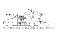
- FIG. 1 is a schematic configuration diagram of a driving support apparatus according to the first embodiment, showing an example in which the driving support apparatus is mounted on a vehicle.
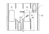
- FIG. 2 is a top view showing a traveling state of the vehicle shown in FIG.
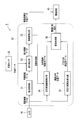
- FIG. 3 is a block diagram showing details of the computer shown in FIG.
- FIG. 4 is a diagram illustrating details of the predetermined position luminance detection unit illustrated in FIG. 3, where FIG. 4A illustrates an image captured by the camera, and FIG. 4B illustrates a position and a pixel on the upper side thereof. The brightness value is shown.
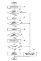
- FIG. 5 is a flowchart showing the adjacent vehicle detection method of the driving support apparatus according to the present embodiment, and shows details of processing of the predetermined position luminance detection unit and factor determination unit shown in FIG. FIG.
- FIG. 6 is a block diagram illustrating details of the computer of the driving support apparatus according to the second embodiment.
- FIG. 7 is a diagram illustrating details of the predetermined position luminance detection unit illustrated in FIG. 6, in which FIG. 7A illustrates an image captured by the camera, and FIG. 7B illustrates the position and the upper pixel thereof. The brightness value is shown.
- FIG. 8 is a flowchart showing the adjacent vehicle detection method of the driving assistance apparatus according to the present embodiment, and shows details of processing of the predetermined position luminance detection unit and the factor determination unit shown in FIG.
- FIG. 9 is a block diagram illustrating details of the computer of the driving support apparatus according to the third embodiment.
- FIG. 1 is a schematic configuration diagram of a driving support device 1 according to the present embodiment, and shows an example in which the driving support device 1 is mounted on a vehicle V.
- the driving support device 1 shown in FIG. 1 provides various information to the driver of the host vehicle V based on the imaging results around the host vehicle V, and includes a camera (imaging means) 10, a vehicle speed sensor 20, and the like.
- the computer 30 and the alarm device 40 are provided.
- the camera 10 shown in FIG. 1 is mounted so that the optical axis is at an angle ⁇ 1 downward from the horizontal at a position of height h behind the host vehicle V.
- the camera 10 images the detection area from this position.
- the vehicle speed sensor 20 detects the traveling speed of the host vehicle V, and for example, a sensor that detects the number of rotations of wheels is applied.
- the computer 30 detects an adjacent vehicle existing around the host vehicle V (hereinafter, another vehicle is exemplified as an example of the adjacent vehicle) based on an image captured by the camera 10. Moreover, in this embodiment, the computer 30 is provided with the structure which does not detect the position of other vehicles accidentally with light, such as the light of other vehicles.
- the warning device 40 warns the driver of the host vehicle V when the adjacent vehicle detected by the computer 30 may come into contact with the host vehicle V.
- FIG. 2 is a top view showing a traveling state of the vehicle shown in FIG.
- the camera 10 can capture the rear side of the host vehicle V.
- Detection areas A1 and A2 for detecting other vehicles are set in the adjacent lane adjacent to the travel lane in which the host vehicle V travels.
- the computer 30 detects whether or not another vehicle exists in the detection areas A1 and A2. Thereby, when the own vehicle V changes lanes, it can be determined whether there is a possibility of contact.
- FIG. 3 is a block diagram showing details of the computer 30 shown in FIG. In FIG. 3, the camera 10, the vehicle speed sensor 20, and the alarm device 40 are also illustrated in order to clarify the connection relationship.
- the computer 30 includes a viewpoint conversion unit 31, a difference detection unit 32, a moving body detection unit (moving body detection unit) 33, and a reflection candidate region detection unit (reflection candidate region detection unit) 34.
- a predetermined position luminance detection unit (predetermined position luminance detection means) 35 and a factor determination unit 36 are provided.
- the moving body detection unit 33 and the reflection candidate region detection unit 34 constitute a detection region setting unit (detection region setting means) in the present embodiment.
- the predetermined position luminance detection unit 35 constitutes a light projection candidate detection unit (light projection candidate detection means) in the present embodiment.
- the viewpoint conversion unit 31 inputs captured image data obtained by imaging with the camera 10, and converts the input captured image data into a bird's-eye image data in a bird's-eye view state.
- the state viewed from a bird's-eye view is a state viewed from the viewpoint of a virtual camera looking down from above, for example, vertically downward.
- This viewpoint conversion is executed as described in, for example, Japanese Patent Application Laid-Open No. 2008-219063.
- the difference detection unit 32 sequentially inputs the bird's-eye image data obtained by the viewpoint conversion of the viewpoint conversion unit 31, and inputs the bird's-eye image data at different times based on the traveling speed of the host vehicle V obtained from the vehicle speed sensor 20. The position of is adjusted. Further, the difference detection unit 32 aligns the positions of the bird's-eye image data at different times, and then detects the difference between those common parts to generate difference image data.
- the moving body detection unit 33 detects a difference value corresponding to the detection areas A1 and A2 in the difference image data generated by the difference detection unit 32, and moves within the detection areas A1 and A2 by threshold processing. Dividing into R1 and road surface region R2. Here, when the moving body region R1 is detected, there is a possibility that another vehicle exists in the region, and the moving body detection unit 33 transmits the fact to the alarm device 40 as moving body detection determination data.
- the moving body region R1 is also detected when a light of another vehicle is reflected on the road surface. That is, as shown in FIG. 2, there is another vehicle in the adjacent lane adjacent to the adjacent lane, and the lights of the other vehicle are reflected on the road surface of the adjacent lane, and this reflected light is detected as the moving body region R1. May end up. In such a case, if the warning device 40 issues a warning, incorrect information will be presented to the driver of the host vehicle V. For this reason, in the present embodiment, such a situation is prevented by the following configuration.
- the reflection candidate area detection unit 34 detects a high luminance part whose luminance is equal to or higher than a predetermined threshold from the imaging area captured by the camera 10. Specifically, the reflection candidate area detection unit 34 detects a high-luminance part where the luminance is equal to or higher than a predetermined threshold, limited to the moving body area R1 detected by the moving body detection unit 33.
- the reflection candidate area detection unit 34 first sets a predetermined threshold value.
- the predetermined threshold is determined based on an angle ⁇ 2 formed by a straight line connecting the optical axis of the camera 10 and a region to be detected (that is, the moving body region R1) in a state where the host vehicle V is viewed from above.
- the smaller the value the higher the adjustment.
- the lights of other vehicles are radiated forward. For this reason, the smaller the angle ⁇ 2, the more light from the lights of other vehicles is captured by the camera 10. Therefore, the predetermined threshold is adjusted higher as the angle ⁇ 2 becomes smaller.
- the reflection candidate area detection unit 34 sets the moving object area R1 as the reflection candidate area R1 if the moving object area R1 is equal to or greater than the predetermined threshold value.
- the threshold setting range and rate of change are set experimentally, and the setting here is merely an example, and the threshold setting is not limited to the above.
- noise may be included in the reflection candidate region R1, and therefore, noise removal can be performed by applying, for example, an opening process to the binary image representing the reflection candidate region R1.
- the reflection candidate region detection unit 34 determines the representative point P1 and the representative luminance value P of the reflection candidate region R1. At this time, the reflection candidate area detection unit 34 sets the representative point P1 as the gravity center position of the reflection candidate area R1 and the representative luminance value P as the luminance of the gravity center position.
- the representative point P1 and the representative luminance value P are not limited to the above.
- the representative point P1 may be a point closer to the own vehicle in the reflection candidate region R1, and the representative luminance value P is an average of the reflection candidate regions R1. Statistical values such as luminance values and 90 percent tile values may be used.
- the predetermined position luminance detection unit 35 looks from above the area of the adjacent lane in a range of a certain direction angle with a straight line connecting the position of the reflection candidate area R1 and the camera 10 in the state where the host vehicle V is viewed upward.
- a region that is equal to or greater than a predetermined luminance value and equal to or greater than a predetermined number of pixels is specified as a light projection candidate region (a region in which an adjacent vehicle is considered a light projection candidate).
- the predetermined number of pixels is 3 pixels or more in the original image of the captured image, but is not limited thereto, and a value of 3 pixels or more may be set. Thereby, the light projection from the light source which is not a vehicle like a streetlight can be excluded from a light projection candidate area
- the predetermined position luminance detection unit 35 is on a straight line connecting the position of the reflection candidate region R1 and the camera 10 with the host vehicle V viewed upward, and with the approximate center line of the adjacent adjacent lane. A position P2 serving as an intersection is detected. Next, the predetermined position luminance detection unit 35 scans and detects the luminance value upward in the real space from the position P2.
- the reason why the position P2 is the intersection with the approximate center line of the adjacent adjacent lane is that the portion with high luminance appears larger than the actual size due to the influence of halation, so if the approximate center line of the adjacent adjacent lane is used as a reference This is because the headlight can be captured even if the other vehicle in the adjacent adjacent lane is slightly displaced laterally.
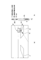
- FIG. 4 is a diagram showing details of the predetermined position luminance detection unit 35 shown in FIG. 3, FIG. 4 (a) shows an image captured by the camera 10, and FIG. 4 (b) shows the position P2 and its upper side. The luminance value of the pixel is shown.
- the predetermined position luminance detection unit 35 detects the position P2, it scans and detects the luminance value upward from the position P2. That is, the luminance value on the line indicated by reference numeral 50 in FIG.
- the predetermined position luminance detection unit 35 detects a section where luminance values equal to or higher than a predetermined value are continuous. As shown in FIG. 4B, the fourth pixel to the tenth pixel above the position P2 have a luminance value greater than or equal to a predetermined value and form a continuous section SE.
- the factor determination unit 36 obtains the representative luminance value Q of the section SE. Similar to the representative luminance value P, the representative luminance value Q may be a luminance value at the center of gravity (center) or a statistical value. Then, the factor determination unit 36 calculates the luminance difference between the representative luminance values P and Q. Further, when the difference in luminance is larger than the threshold value TH, the factor determination unit 36 determines that the reflection candidate region R1 is a light reflected from the other vehicle in the adjacent adjacent lane on the road surface. On the other hand, if not, the factor determination unit 36 determines that the reflection candidate region R1 is light from the lights of other vehicles in the adjacent lane, and regards that the adjacent vehicle exists.
- the factor determination unit 36 also executes the following processing in order to detect other vehicles in the adjacent lane with higher accuracy.
- the factor determination unit 36 determines whether the number of pixels in the section SE is equal to or less than a specified value.
- the adjacent vehicle detection unit 36b determines that the section SE is not the light of the other vehicle in the adjacent adjacent lane but the light of the adjacent vehicle, and detects the adjacent vehicle.
- the adjacent vehicle detection unit 36b determines that the section SE is a light of another vehicle in the adjacent adjacent lane. That is, it is determined that the reflection candidate region R1 is a light reflected from the other vehicle in the adjacent adjacent lane on the road surface.
- the factor determination unit 36 obtains a distance D between the lowest point P3 of the section SE detected by the predetermined position luminance detection unit 35 and the position P2. And the factor determination part 36 determines whether this distance D is below a predetermined distance. When the distance is equal to or less than the predetermined distance, the position of the light of the other vehicle in the adjacent adjacent lane is too low, and it can be determined that the light is not in the other vehicle of the adjacent adjacent lane. For this reason, the factor determination unit 36 determines that the section SE is a light of an adjacent vehicle, and detects the adjacent vehicle. On the other hand, when the distance D is not less than or equal to the predetermined distance, the factor determination unit 36 determines that the section SE is a light of another vehicle in the adjacent adjacent lane. That is, it is determined that the reflection candidate region R1 is a light reflected from the other vehicle in the adjacent adjacent lane on the road surface.
- the driving support device is a driving support device that provides various information to the driver from the imaging result around the host vehicle, and is mounted on the host vehicle, and the host vehicle
- An imaging unit (camera 10) that images the rear side of the vehicle
- a detection region setting unit (movement) that sets a detection region for detecting the presence of the adjacent vehicle on the adjacent lane from the imaging data captured by the imaging unit Body detection unit 33 and reflection candidate region detection unit 34)
- a light projection candidate detection unit predetermined position luminance detection unit 35
- the detection region setting unit predetermined position luminance detection unit 35
- a factor determination unit for determining whether or not there is a light projection candidate indicating the presence of the adjacent vehicle in the detected detection area, and the factor determination unit determines that the light projection of the adjacent vehicle has occurred. If the driver next to the driver An information providing unit (alarm device 40) that provides information on the presence of the vehicle, and the factor determination unit detects an imaging position (corresponding to the distance D) of the projection candidate detected by the projection candidate detection unit. Thus, it can be said that it is determined whether or not it is a floodlight of the adjacent vehicle.
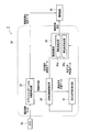
- FIG. 5 is a flowchart showing the adjacent vehicle detection method of the driving assistance apparatus 1 according to the present embodiment, and shows details of processing of the predetermined position luminance detection unit 35 and factor determination unit 36 shown in FIG.
- the predetermined position luminance detection unit 35 has a certain direction angle with a straight line connecting the position of the reflection candidate region R ⁇ b> 1 and the camera 10 in the state where the host vehicle V is viewed upward.
- An area having a predetermined luminance value or more is identified as a light projection candidate area RS from within the area of the adjacent adjacent lane in the range (S1).
- the predetermined position luminance detection unit 35 determines whether or not the light projection candidate region RS is equal to or larger than a predetermined number of pixels (a prescribed value of the number of pixels) (S2). And when it is judged that the light projection candidate area
- a predetermined number of pixels a prescribed value of the number of pixels
- the predetermined position luminance detection unit 35 scans and detects the luminance value upward in the real space at the representative position in the light projection candidate region RS.
- the predetermined position luminance detection unit 35 scans and detects the luminance value upward in the real space at the representative position in the projection candidate region RS (S4).
- the predetermined position luminance detection unit 35 scans and detects the luminance value upward in the real space from the position P2 specified as the representative position in the light projection candidate region RS, and selects the section SE having a luminance value equal to or higher than the predetermined value. Detect (S4).
- the factor determination unit 36 determines whether or not the number of pixels in the section SE is equal to or less than a specified value (S5).
- the section SE When it is determined that the number of pixels in the section SE is not less than the specified value (S5: NO), that is, since the number of pixels is larger than the specified value, the section SE is highly likely to be a light of another vehicle in the adjacent adjacent lane.
- the factor determination unit 36 determines that the reflection candidate region R1 is reflected by the lights of other vehicles in the adjacent adjacent lane (S3). Thereafter, the process shown in FIG. 5 ends.
- the factor determination unit 36 calculates the distance D between the lowest point P3 of the section SE and the specified position P2 ( S6). Next, the factor determination unit 36 determines whether or not the distance D is equal to or less than a predetermined distance (S7).
- This distance D is not limited to the section SE, and may be set as a distance in the vehicle width direction from the camera to the light source of the adjacent vehicle. Moreover, you may set combining these.
- the vehicle width direction distance is set in the range of 1 to 4.5 m, for example, and if the vehicle width direction distance is fixed to 6.5 m, the height direction distance is set. Set the distance in the range of 60-90 cm.
- these values are only examples and are not limited to these.
- the section SE may be a light of other vehicles in the adjacent lane.
- the factor determination unit 36 determines that the reflection candidate region R1 is reflected by the light of the other vehicle in the adjacent adjacent lane (S3). Thereafter, the process shown in FIG. 5 ends.
- the factor determination unit 36 detects the representative luminance value Q of the section SE (S8). Next, the factor determination unit 36 determines whether or not the representative luminance value Q> the representative luminance value P + the threshold value TH (S9).
- the threshold value TH is set to a luminance level of 5 to 10, for example.
- the factor determination unit 36 When it is determined by the process of step S3 that the reflection candidate area R1 is a reflection of the light of the other vehicle in the adjacent lane, the factor determination unit 36 outputs an alarm suppression signal as shown in FIG. . Thereby, even if the host vehicle V changes lanes, it is possible to prevent a situation where an alarm is issued when there is no possibility of contact with another vehicle and there is no need for an alarm.
- the factor determination unit 36 does not output an alarm suppression signal, and the alarm device 40 notifies the driver of the presence of the adjacent vehicle by a buzzer or a lamp. Will be informed.
- the driving support method is a driving support method that provides various information to the driver from the imaging result around the host vehicle imaged by the imaging unit (camera 10).
- a detection region for detecting the presence of an adjacent vehicle on an adjacent lane from an imaging step of imaging the rear side of the host vehicle by an imaging unit mounted on the host vehicle and imaging data captured in the imaging step A detection region setting step for setting a light projection candidate, a light projection candidate detection step for detecting a light projection candidate for projecting light with a luminance equal to or higher than a predetermined threshold, and the presence of the adjacent vehicle in the detection region set in the detection region setting step
- a factor determination step for determining whether or not there is a light projection candidate, and an information provision for providing information on the presence of the adjacent vehicle to the driver when it is determined in the factor determination step that the light is emitted from the adjacent vehicle.
- the adjacent vehicle is projected by detecting an imaging position (corresponding to the distance D) of the projection candidate detected in the projection candidate detection step in the factor determination step. It can be
- the other vehicle in the adjacent lane is detected by detecting the reflection candidate region R1 whose luminance is equal to or greater than the predetermined threshold from the imaging region. Or the road surface reflected by the lights of other vehicles in the adjacent adjacent lane. Further, the brightness at a position that is a predetermined distance away from the host vehicle V is detected on a straight line connecting the position of the reflection candidate region R1 and the camera 10. For this reason, when the reflection candidate region R1 is a road surface reflected by the light of another vehicle, it is possible to detect the position of the light of the other vehicle by detecting a position separated by a predetermined distance passing through the reflected road surface. Become.
- the reflection candidate region R1 is a road surface reflected by the light of the other vehicle
- the luminance difference increases because the light of the other vehicle is present at a position away from the predetermined distance and there is a brighter portion. Otherwise, the brightness difference tends to be small. Therefore, the position of the light of the other vehicle can be determined from the luminance difference, and the detection accuracy of the adjacent vehicle can be improved.
- the predetermined threshold is adjusted higher as the angle ⁇ 2 formed by the optical axis of the camera 10 and the straight line connecting the region to be detected (that is, the moving body region R1) and the camera 10 decreases.
- the amount of light input to the camera 10 tends to increase from the light located near the optical axis of the camera 10. For this reason, an appropriate threshold value can be set by adjusting the predetermined threshold value higher as the angle ⁇ 2 becomes smaller.
- a region where an adjacent vehicle can exist that is, the moving body region R1
- a reflection candidate region R1 having a luminance equal to or higher than a predetermined threshold is detected only in the detected region. For this reason, it is possible to reduce the processing amount without executing the above-described processing for an unnecessary area.
- the position P2 in the adjacent adjacent lane is specified, and the luminance value is scanned and detected upward in the real space from the specified position P2. For this reason, the position of the light of the other vehicle in the adjacent adjacent lane can be captured more accurately.
- the luminance value is scanned and detected upward in the real space from the specified position P2, and the section SE in which the luminance value equal to or higher than the predetermined value is extracted, and the number of pixels in the extracted continuous section SE is defined. If it is less than or equal to the value, it is determined that an adjacent vehicle has been detected. For this reason, when the number of pixels in the extracted consecutive section SE is small and less than the size of the light, it is not erroneously determined that the light of the other vehicle in the adjacent adjacent lane is reflected for the section SE, and the detection is performed. Accuracy can be increased.
- the distance between the lowest point P3 of the extracted continuous section SE and the specified position P2 is equal to or less than a predetermined distance, it is determined that an adjacent vehicle has been detected. For this reason, when the lowest point P3 of the extracted continuous section SE is not at least the height of the light position of the other vehicle and the distance from the specified position P2 is short, the other vehicle in the adjacent adjacent lane in the section SE Detection accuracy can be improved without erroneously determining that the light is written.
- FIG. 6 is a block diagram showing details of the computer 30 of the driving support apparatus 2 according to the second embodiment.
- the camera 10 and the alarm device 40 are also illustrated in order to clarify the connection relationship.
- the computer 30 includes a factor determination unit 36 that includes a luminance difference detection unit (luminance difference detection unit) 36 a and an adjacent vehicle detection unit (adjacent vehicle detection unit) 36 b. .
- the moving body detection unit 33 and the reflection candidate region detection unit 34 constitute a detection region setting unit (detection region setting means) in the present embodiment.
- the predetermined position luminance detection unit 35 constitutes a light projection candidate detection unit (light projection candidate detection means) in the present embodiment.
- FIG. 7 is a diagram illustrating details of the predetermined position luminance detection unit 35 according to the present embodiment illustrated in FIG. 6, in which FIG. 7A illustrates an image captured by the camera 10, and FIG. The luminance values of P2 and the pixels above it are shown.
- the predetermined position luminance detection unit 35 detects the position P2, it scans and detects the luminance value upward from the position P2. That is, the luminance value on the line indicated by reference numeral 50 in FIG.
- the predetermined position luminance detection unit 35 detects a section where luminance values equal to or higher than a predetermined value are continuous. As shown in FIG. 7B, the fourth pixel to the tenth pixel above the position P2 have a luminance value greater than or equal to a predetermined value and form a continuous section SE1. Similarly, the thirteenth and fourteenth pixels above the position P2 also have a luminance value greater than or equal to a predetermined value and form a continuous section SE2.
- the adjacent vehicle detection unit 36b has the maximum number of consecutive ones of the sections SE1 and SE2.
- the section SE1 is selected.
- the luminance difference detection unit 36a obtains the representative luminance value Q of the section SE1. Similar to the representative luminance value P, the representative luminance value Q may be a luminance value at the center of gravity (center) or a statistical value. Then, the luminance difference detection unit 36a calculates the luminance difference between the representative luminance values P and Q. When this luminance difference is larger than the threshold value TH, the adjacent vehicle detection unit 36b determines that the reflection candidate region R1 is a light reflected from the other vehicle in the adjacent adjacent lane on the road surface. On the other hand, if not, the adjacent vehicle detection unit 36b determines that the reflection candidate region R1 is light from the lights of other vehicles in the adjacent lane, and regards that the adjacent vehicle exists.
- the adjacent vehicle detection unit 36b also executes the following processing in order to detect other vehicles in the adjacent lane with higher accuracy.
- the adjacent vehicle detection unit 36b determines whether the number of pixels in the section SE1 is equal to or less than a specified value.
- the case where the number of pixels of the extracted continuous section SE1 is equal to or less than the predetermined value can be said that the portion with high luminance is small and does not satisfy the size of the light of the other vehicle in the adjacent adjacent lane.
- the adjacent vehicle detection unit 36b determines that the section SE1 is not the light of the other vehicle in the adjacent adjacent lane but the light of the adjacent vehicle, and detects the adjacent vehicle.
- the adjacent vehicle detection unit 36b determines that the section SE1 is a light of another vehicle in the adjacent adjacent lane. That is, it is determined that the reflection candidate region R1 is a light reflected from the other vehicle in the adjacent adjacent lane on the road surface.
- the adjacent vehicle detection unit 36b obtains a distance D between the lowest point P3 of the section SE1 detected by the predetermined position luminance detection unit 35 and the position P2. And the adjacent vehicle detection part 36b judges whether this distance D is below a predetermined distance. When the distance is equal to or less than the predetermined distance, the position of the light of the other vehicle in the adjacent adjacent lane is too low, and it can be determined that the light is not in the other vehicle of the adjacent adjacent lane. For this reason, the adjacent vehicle detection unit 36b determines that the section SE1 is a light of the adjacent vehicle, and detects the adjacent vehicle.
- the adjacent vehicle detection unit 36b determines that the section SE1 is a light of another vehicle in the adjacent adjacent lane. That is, it is determined that the reflection candidate region R1 is a light reflected from the other vehicle in the adjacent adjacent lane on the road surface.
- the driving support device is a driving support device that provides various information to the driver from the imaging results around the host vehicle, and is mounted on the host vehicle. Detection that sets a detection region for detecting the presence of an adjacent vehicle on an adjacent lane from an imaging unit (camera 10) that captures the rear side of the host vehicle and imaging data captured by the imaging unit
- a region setting unit (moving body detection unit 33 and reflection candidate region detection unit 34), a light projection candidate detection unit (predetermined position luminance detection unit 35) that detects a light projection candidate that projects light with a luminance equal to or higher than a predetermined threshold, and the detection
- a factor determination unit factor determination unit (factor determination unit 36) for determining whether or not there is a light projection candidate indicating the presence of the adjacent vehicle in the detection region set by the region setting unit, and the factor determination unit projects the projection of the adjacent vehicle.
- An information providing unit for providing information on the presence of the adjacent vehicle to the driver, and the factor determination unit is configured to capture a projection candidate (distance D) detected by the projection candidate detection unit. It can be said that it is determined whether or not the adjacent vehicle is light-projected.
- FIG. 8 is a flowchart showing the adjacent vehicle detection method of the driving support apparatus 2 according to the present embodiment, and shows details of processing of the predetermined position luminance detection unit 35 and the factor determination unit 36 shown in FIG.
- the predetermined position luminance detection unit 35 has a certain direction angle with a straight line connecting the position of the reflection candidate region R1 and the camera 10 in the state where the host vehicle V is viewed upward.
- An area having a predetermined luminance value or more is specified as a light projection candidate area RS from within the area of the adjacent adjacent lane in the range (S11).
- the predetermined position luminance detection unit 35 determines whether or not the light projection candidate region RS is equal to or greater than a predetermined number of pixels (a prescribed value for the number of pixels) (S12). And when it is judged that the light projection candidate area
- a predetermined number of pixels a prescribed value for the number of pixels
- the predetermined position luminance detection unit 35 scans and detects the luminance value upward in the real space at the representative position in the light projection candidate region RS.
- the prescribed value of the number of pixels is, for example, 3 pixels or more in the original image of the captured image.
- the present invention is not limited to this, and a value of 3 pixels or more may be set.
- the predetermined position luminance detection unit 35 scans and detects the luminance value upward in the real space at the representative position in the projection candidate region RS (S14).
- the predetermined position luminance detection unit 35 scans and detects the luminance value upward in the real space from the position P2 specified as the representative position in the light projection candidate region RS, and has a section SE1, which has a luminance value equal to or higher than the predetermined value. The largest one of SE2 is detected (S14).
- the adjacent vehicle detection unit 36b determines whether or not the number of pixels in the maximum section SE1 is equal to or less than a specified value (S15).
- the adjacent vehicle detection unit 36b determines that the reflection candidate region R1 is reflected by the lights of other vehicles in the adjacent adjacent lane (S13). Thereafter, the process shown in FIG. 8 ends.
- the adjacent vehicle detection unit 36b determines the distance D between the lowest point P3 in the section SE1 and the specified position P2. Calculate (S16). Next, the adjacent vehicle detection unit 36b determines whether or not the distance D is equal to or less than a predetermined distance (S17). This distance D is not limited to the section SE1, but may be set as a distance in the vehicle width direction from the camera to the light source of the adjacent vehicle. Moreover, you may set combining these.
- the vehicle width direction distance is set in the range of 1 m to 4.5 m, for example, and if the vehicle width direction distance is fixed to 6.5 m, the height direction distance is set. Set the distance in the range of 60-90 cm.
- these values are only examples and are not limited to these.
- the section SE1 can be a light of other vehicles in the adjacent lane.
- the adjacent vehicle detection unit 36b determines that the reflection candidate region R1 is reflected by the lights of other vehicles in the adjacent adjacent lane (S13). Thereafter, the process shown in FIG. 8 ends.
- the luminance difference detection unit 36a detects the representative luminance value Q of the section SE1 which is the maximum section (S18). Next, the luminance difference calculation unit 36a determines whether or not representative luminance value Q> representative luminance value P + threshold TH (S19).
- the threshold value TH is set to a luminance level of 5 to 10, for example.
- the factor determination unit 36 If it is determined by the processing in step S13 that the reflection candidate area R1 is a reflection of the light of another vehicle in the adjacent lane, the factor determination unit 36 outputs an alarm suppression signal as shown in FIG. . Thereby, even if the host vehicle V changes lanes, it is possible to prevent a situation where an alarm is issued when there is no possibility of contact with another vehicle and there is no need for an alarm.
- step S20 if it is determined in the process of step S20 that another vehicle exists in the adjacent lane, the factor determination unit 36 does not output an alarm suppression signal, and the alarm device 40 notifies the driver of the presence of the adjacent vehicle by a buzzer, a lamp, or the like. Will be informed.
- the driving support that provides various information to the driver from the imaging result around the own vehicle imaged by the imaging unit (camera 10).
- a method for detecting the presence of an adjacent vehicle on an adjacent lane from an imaging step of imaging the rear side of the own vehicle by an imaging unit mounted on the own vehicle and imaging data captured in the imaging step A detection region setting step for setting a detection region to perform, a light projection candidate detection step for detecting a light projection candidate that projects light with a luminance equal to or higher than a predetermined threshold, and the adjacent to the detection region set in the detection region setting step
- a factor determination step for determining whether or not there is a light projection candidate indicating the presence of the vehicle, and the presence of the adjacent vehicle to the driver when it is determined in the factor determination step that the light is projected from the adjacent vehicle.
- the other vehicle in the adjacent lane is detected by detecting the reflection candidate region R1 in which the luminance is equal to or greater than the predetermined threshold from the imaging region. Or the road surface reflected by the lights of other vehicles in the adjacent adjacent lane. Further, the brightness at a position that is a predetermined distance away from the host vehicle V is detected on a straight line connecting the position of the reflection candidate region R1 and the camera 10. For this reason, when the reflection candidate region R1 is a road surface reflected by the light of another vehicle, it is possible to detect the position of the light of the other vehicle by detecting a position separated by a predetermined distance passing through the reflected road surface. Become.
- the reflection candidate region R1 is a road surface reflected by the light of the other vehicle
- the luminance difference increases because the light of the other vehicle is present at a position away from the predetermined distance and there is a brighter portion. Otherwise, the brightness difference tends to be small. Therefore, the position of the light of the other vehicle can be determined from the luminance difference, and the detection accuracy of the adjacent vehicle can be improved.
- the predetermined threshold is adjusted higher as the angle ⁇ 2 formed by the optical axis of the camera 10 and the straight line connecting the region to be detected (that is, the moving body region R1) and the camera 10 decreases.
- the amount of light input to the camera 10 tends to increase from the light located near the optical axis of the camera 10. For this reason, an appropriate threshold value can be set by adjusting the predetermined threshold value higher as the angle ⁇ 2 becomes smaller.
- a region where an adjacent vehicle can exist that is, the moving body region R1
- a reflection candidate region R1 having a luminance equal to or higher than a predetermined threshold is detected only in the detected region. For this reason, it is possible to reduce the processing amount without executing the above-described processing for an unnecessary area.
- the position P2 in the adjacent adjacent lane is specified, and the luminance value is scanned and detected upward in the real space from the specified position P2. For this reason, the position of the light of the other vehicle in the adjacent adjacent lane can be captured more accurately.
- the luminance value is scanned and detected upward in the real space from the specified position P2, and the sections SE1 and SE2 in which the luminance value equal to or higher than the predetermined value is extracted are extracted, and the number of pixels in the extracted continuous section S1 is extracted. Is equal to or less than the specified value, it is determined that an adjacent vehicle has been detected. For this reason, when the number of pixels in the extracted continuous section SE1 is small and less than the size of the light, it is not erroneously determined that the light of the other vehicle in the adjacent adjacent lane is reflected in the section SE1, and the detection is performed. Accuracy can be increased.
- the distance between the lowest point P3 of the extracted continuous section SE1 and the specified position P2 is equal to or less than a predetermined distance, it is determined that an adjacent vehicle has been detected. For this reason, when the lowest point P3 of the extracted continuous section SE1 is not at least the height of the light position of the other vehicle and the distance to the specified position P2 is short, the other vehicle in the adjacent adjacent lane in the section SE1 Detection accuracy can be improved without erroneously determining that the light is written.
- FIG. 9 is a block diagram showing details of the computer 30 of the travel support apparatus 3 according to the third embodiment.
- the camera 10 and the alarm device 40 are also illustrated in order to clarify the connection relationship.
- the computer 30 includes a moving body detection unit (region detection unit) 37 based on an optical flow instead of the viewpoint conversion unit 31, the difference detection unit 32, and the moving body detection unit 33. ing.
- the moving body detection unit 37 based on the optical flow detects other vehicles from the movement vector of the object in the image, and specifically detects other vehicles as described in Japanese Patent No. 4367475. At this time, the mobile body detection unit 37 based on the optical flow detects the mobile body region R1 and transmits it to the reflection candidate region detection unit 34, similarly to the mobile body detection unit 33 shown in the second embodiment.
- luminance detection part 35, and the factor judgment part 36 is the same as that of 2nd Embodiment.
- the moving object detection unit 33 and the reflection candidate region detection unit 34 constitute a detection region setting unit (detection region setting means) in the present embodiment.
- the predetermined position luminance detection unit 35 constitutes a light projection candidate detection unit (light projection candidate detection means) in the present embodiment.
- the detection accuracy of the adjacent vehicle can be improved as in the second embodiment.
- an appropriate threshold can be set, and the amount of processing can be reduced.
- the position of the light of the other vehicle in the adjacent adjacent lane can be captured more accurately, and the detection accuracy can be increased.
- the moving body detection unit 37 based on the optical flow since the moving body detection unit 37 based on the optical flow is provided, the moving body region R1 can be detected without a signal from the vehicle speed sensor 20.
- the travel support devices 1 and 2 are mounted on the vehicle V.
- the present invention is not limited to this, and may be mounted on a motorcycle, an automatic navigation robot, or the like.
- the adjacent vehicle may be a two-wheeled vehicle or a bicycle.
- the weather during traveling of the host vehicle V is not particularly mentioned.
- the road surface reflection (specular reflection) by the light of the other vehicle increases. Therefore, when it rains, it is used in step S7 in FIG. 5 and step S17 in FIG. 8 (step for determining whether the reflection candidate area R1 is a road surface reflection of a light from another vehicle in the adjacent lane or a light from another vehicle in the adjacent lane).
- a threshold value THR that is smaller than the threshold value TH used at times other than rainy weather can be used as the threshold value.
- the candidate reflection region R1 is a light of the other vehicle in the adjacent lane. (S8, S18). Thereby, it becomes possible to detect an adjacent vehicle according to the weather at the time of the own vehicle V's travel.
- the reflection candidate region R1 is It is determined that the mirror reflection is caused by the light of the vehicle other than the adjacent oblique line. In that case, mask processing related to specular reflection in the reflection region candidate R1 is performed for a predetermined period thereafter. In this case, as the reflection candidate area R1 is further rearward with respect to the own vehicle V (that is, the angle ⁇ 2 in FIG. 2 is smaller), the reflection candidate area R1 exists in the overtaking lane with respect to the own vehicle V. In some cases, the period is set longer than in other cases.
- the present invention can provide a driving support device and a driving support method that can detect an adjacent vehicle with high accuracy.
Landscapes
- Physics & Mathematics (AREA)
- General Physics & Mathematics (AREA)
- Engineering & Computer Science (AREA)
- Multimedia (AREA)
- Theoretical Computer Science (AREA)
- Signal Processing (AREA)
- Traffic Control Systems (AREA)
- Image Analysis (AREA)
- Image Processing (AREA)
Priority Applications (7)
| Application Number | Priority Date | Filing Date | Title |
|---|---|---|---|
| EP12770754.5A EP2698778B1 (de) | 2011-04-13 | 2012-04-11 | Fahrassistenzvorrichtung und verfahren zur erkennung benachbarter fahrzeuge |
| MX2013008808A MX2013008808A (es) | 2011-04-13 | 2012-04-11 | Dispositivo de asistencia de conduccion y metodo de deteccion de vehiculo adyacente al mismo. |
| JP2013509947A JP5637302B2 (ja) | 2011-04-13 | 2012-04-11 | 走行支援装置及びその隣接車両検出方法 |
| US13/823,414 US10142595B2 (en) | 2011-04-13 | 2012-04-11 | Driving assistance device and method of detecting vehicle adjacent thereto |
| RU2013132011/08A RU2546547C1 (ru) | 2011-04-13 | 2012-04-11 | Устройство помощи при вождении и способ обнаружения транспортного средства рядом с ним |
| BR112013019405-7A BR112013019405B1 (pt) | 2011-04-13 | 2012-04-11 | Dispositivo e método de assistência à direção |
| CN201280007017.9A CN103348394B (zh) | 2011-04-13 | 2012-04-11 | 行驶辅助装置及其相邻车辆检测方法 |
Applications Claiming Priority (2)
| Application Number | Priority Date | Filing Date | Title |
|---|---|---|---|
| JP2011088726 | 2011-04-13 | ||
| JP2011-088726 | 2011-04-13 |
Publications (1)
| Publication Number | Publication Date |
|---|---|
| WO2012141219A1 true WO2012141219A1 (ja) | 2012-10-18 |
Family
ID=47009386
Family Applications (1)
| Application Number | Title | Priority Date | Filing Date |
|---|---|---|---|
| PCT/JP2012/059914 Ceased WO2012141219A1 (ja) | 2011-04-13 | 2012-04-11 | 走行支援装置及びその隣接車両検出方法 |
Country Status (9)
| Country | Link |
|---|---|
| US (1) | US10142595B2 (de) |
| EP (1) | EP2698778B1 (de) |
| JP (1) | JP5637302B2 (de) |
| CN (1) | CN103348394B (de) |
| BR (1) | BR112013019405B1 (de) |
| MX (1) | MX2013008808A (de) |
| MY (1) | MY170485A (de) |
| RU (1) | RU2546547C1 (de) |
| WO (1) | WO2012141219A1 (de) |
Cited By (2)
| Publication number | Priority date | Publication date | Assignee | Title |
|---|---|---|---|---|
| WO2016092925A1 (ja) * | 2014-12-09 | 2016-06-16 | クラリオン株式会社 | 接近車両検出装置 |
| WO2021112009A1 (ja) * | 2019-12-06 | 2021-06-10 | ソニーグループ株式会社 | 情報処理システムおよび学習方法 |
Families Citing this family (18)
| Publication number | Priority date | Publication date | Assignee | Title |
|---|---|---|---|---|
| US9495602B2 (en) * | 2013-10-23 | 2016-11-15 | Toyota Motor Engineering & Manufacturing North America, Inc. | Image and map-based detection of vehicles at intersections |
| DE102014204002A1 (de) * | 2014-03-05 | 2015-09-10 | Conti Temic Microelectronic Gmbh | Verfahren zur Identifikation eines projizierten Symbols auf einer Straße in einem Fahrzeug, Vorrichtung und Fahrzeug |
| CN112866566B (zh) * | 2014-05-29 | 2023-05-09 | 株式会社尼康 | 驾驶辅助装置及驾驶辅助装置搭载车辆 |
| US9478137B1 (en) | 2015-06-17 | 2016-10-25 | Ford Global Technologies, Llc | Detecting and communicating lane splitting maneuver |
| US9829888B2 (en) * | 2015-11-17 | 2017-11-28 | Ford Global Technologies, Llc | Distinguishing lane markings for a vehicle to follow |
| JP6583121B2 (ja) * | 2016-04-21 | 2019-10-02 | 株式会社デンソー | 運転支援装置 |
| DE102016218013A1 (de) * | 2016-09-20 | 2018-03-22 | Robert Bosch Gmbh | Verfahren und Vorrichtung zum automatisierten Anpassen einer Helligkeit wenigstens eines Scheinwerfers für ein Fahrzeug |
| JP6837262B2 (ja) * | 2016-12-27 | 2021-03-03 | 日立Astemo株式会社 | 走行可能領域検出装置及び走行支援システム |
| CN108197523B (zh) * | 2017-05-15 | 2021-09-14 | 武汉光庭科技有限公司 | 基于图像转换及轮廓邻域差异的夜间车辆检测方法及系统 |
| JP6776213B2 (ja) * | 2017-11-01 | 2020-10-28 | 株式会社東芝 | 軌道識別装置 |
| EP3855408B1 (de) * | 2018-09-17 | 2022-11-02 | Nissan Motor Co., Ltd. | Verfahren zur vorhersage des fahrzeugverhaltens und vorrichtung zur vorhersage des fahrzeugverhaltens |
| JP7111586B2 (ja) * | 2018-11-09 | 2022-08-02 | 株式会社Soken | 物体検出装置 |
| WO2020129522A1 (ja) * | 2018-12-18 | 2020-06-25 | 日立オートモティブシステムズ株式会社 | 画像処理装置 |
| JP7034231B1 (ja) * | 2020-10-20 | 2022-03-11 | 三菱電機株式会社 | 車両位置検出装置および車両位置検出方法 |
| JP7494701B2 (ja) * | 2020-10-23 | 2024-06-04 | トヨタ自動車株式会社 | 制御装置、制御方法、及び街灯 |
| JP7598488B2 (ja) * | 2021-11-23 | 2024-12-11 | 株式会社デンソー | 周辺監視装置及びプログラム |
| CN116363622B (zh) * | 2021-12-28 | 2026-03-20 | 北京万集科技股份有限公司 | 车辆检测方法及其相关设备 |
| CN114782447B (zh) * | 2022-06-22 | 2022-09-09 | 小米汽车科技有限公司 | 路面检测方法、装置、车辆、存储介质及芯片 |
Citations (7)
| Publication number | Priority date | Publication date | Assignee | Title |
|---|---|---|---|---|
| JP2006085285A (ja) * | 2004-09-14 | 2006-03-30 | Matsushita Electric Ind Co Ltd | 危険車両予測装置 |
| JP2007276733A (ja) * | 2006-04-11 | 2007-10-25 | Nissan Motor Co Ltd | 車両用運転操作補助装置および車両用運転操作補助装置を備えた車両 |
| JP2008219063A (ja) | 2007-02-28 | 2008-09-18 | Sanyo Electric Co Ltd | 車両周辺監視装置及び方法 |
| JP2009211309A (ja) * | 2008-03-03 | 2009-09-17 | Honda Motor Co Ltd | 走行支援装置 |
| JP4367475B2 (ja) | 2006-10-06 | 2009-11-18 | アイシン精機株式会社 | 移動物体認識装置、移動物体認識方法及びコンピュータプログラム |
| JP2010205087A (ja) | 2009-03-04 | 2010-09-16 | Honda Motor Co Ltd | 車両の周辺監視装置 |
| WO2011037109A1 (ja) * | 2009-09-25 | 2011-03-31 | クラリオン株式会社 | センサコントローラ、ナビゲーション装置、センサ制御方法 |
Family Cites Families (23)
| Publication number | Priority date | Publication date | Assignee | Title |
|---|---|---|---|---|
| DE2623643C2 (de) * | 1976-05-26 | 1986-11-20 | Daimler-Benz Ag, 7000 Stuttgart | Verfahren zum selbsttätigen Regeln des Sicherheitsabstandes eines Fahrzeuges zu vorausfahrenden Fahrzeugen und Vorrichtung zur Durchführung dieses Verfahrens |
| RU2034325C1 (ru) * | 1991-06-20 | 1995-04-30 | Святослав Иванович АРСЕНИЧ | Противоослепительная система освещения пути транспортного средства |
| RU2064420C1 (ru) * | 1993-04-16 | 1996-07-27 | Валерий Павлович Швецов | Противоослепительная система дорожных транспортных средств (варианты) |
| DE19704466A1 (de) * | 1997-02-06 | 1998-08-13 | Bosch Gmbh Robert | Einrichtung zur Regelung der Leuchtweite von Scheinwerfern von Fahrzeugen |
| JP2003211309A (ja) * | 2002-01-17 | 2003-07-29 | Seiwa Seiki Kk | 旋盤用工具チャック装置 |
| AU2003225228A1 (en) * | 2002-05-03 | 2003-11-17 | Donnelly Corporation | Object detection system for vehicle |
| DE102004009924A1 (de) * | 2004-02-23 | 2005-09-01 | Valeo Schalter Und Sensoren Gmbh | Verfahren und Warnvorrichtung zum grafischen Aufbereiten eines Bildes einer Kamera |
| JP4093208B2 (ja) * | 2004-05-28 | 2008-06-04 | トヨタ自動車株式会社 | 車両用走路判定装置 |
| TWI236990B (en) * | 2004-10-07 | 2005-08-01 | Chi-Ruei Huang | Pre-warning system of deviated lane for vehicles |
| US7720580B2 (en) | 2004-12-23 | 2010-05-18 | Donnelly Corporation | Object detection system for vehicle |
| DE102005027653A1 (de) * | 2005-06-15 | 2006-12-21 | Robert Bosch Gmbh | Vorrichtung zur Ortung von Objekten im Toten Winkel eines Fahrzeugs |
| DE102005054972A1 (de) * | 2005-10-27 | 2007-05-03 | Daimlerchrysler Ag | Verfahren zur Totwinkelüberwachung bei Fahrzeugen |
| US7444241B2 (en) * | 2005-12-09 | 2008-10-28 | Gm Global Technology Operations, Inc. | Method for detecting or predicting vehicle cut-ins |
| JP4466608B2 (ja) * | 2006-05-18 | 2010-05-26 | 株式会社デンソー | 車両用前照灯装置 |
| DE102006027326B4 (de) * | 2006-06-13 | 2026-01-22 | Robert Bosch Gmbh | Spurwechselassistent für Kraftfahrzeuge |
| DE102006055903A1 (de) * | 2006-11-27 | 2008-05-29 | Adc Automotive Distance Control Systems Gmbh | Erkennung von Fahrzeuglichtern mit einer Kamera |
| US8311730B2 (en) * | 2006-11-29 | 2012-11-13 | Neff Ryan A | Vehicle position determination system |
| JP4309920B2 (ja) * | 2007-01-29 | 2009-08-05 | 株式会社東芝 | 車載用ナビゲーション装置、路面標示識別プログラム及び路面標示識別方法 |
| DE102008005314A1 (de) * | 2008-01-21 | 2009-07-23 | Robert Bosch Gmbh | Verfahren und Vorrichtung zum Erfassen eines vorbeifahrenden Fahrzeuges bei Dunkelheit |
| JP5253017B2 (ja) * | 2008-07-03 | 2013-07-31 | アルパイン株式会社 | 周辺監視装置、障害物検出方法及びコンピュータプログラム |
| JP5068779B2 (ja) * | 2009-02-27 | 2012-11-07 | 現代自動車株式会社 | 車両周囲俯瞰画像表示装置及び方法 |
| EP2473871B1 (de) * | 2009-09-01 | 2015-03-11 | Magna Mirrors Of America, Inc. | Abbildungs- und anzeigesystem für fahrzeuge |
| JP5491235B2 (ja) * | 2010-03-02 | 2014-05-14 | 東芝アルパイン・オートモティブテクノロジー株式会社 | カメラキャリブレーション装置 |
-
2012
- 2012-04-11 RU RU2013132011/08A patent/RU2546547C1/ru active
- 2012-04-11 US US13/823,414 patent/US10142595B2/en active Active
- 2012-04-11 EP EP12770754.5A patent/EP2698778B1/de active Active
- 2012-04-11 BR BR112013019405-7A patent/BR112013019405B1/pt active IP Right Grant
- 2012-04-11 MY MYPI2013000681A patent/MY170485A/en unknown
- 2012-04-11 JP JP2013509947A patent/JP5637302B2/ja active Active
- 2012-04-11 WO PCT/JP2012/059914 patent/WO2012141219A1/ja not_active Ceased
- 2012-04-11 MX MX2013008808A patent/MX2013008808A/es active IP Right Grant
- 2012-04-11 CN CN201280007017.9A patent/CN103348394B/zh active Active
Patent Citations (7)
| Publication number | Priority date | Publication date | Assignee | Title |
|---|---|---|---|---|
| JP2006085285A (ja) * | 2004-09-14 | 2006-03-30 | Matsushita Electric Ind Co Ltd | 危険車両予測装置 |
| JP2007276733A (ja) * | 2006-04-11 | 2007-10-25 | Nissan Motor Co Ltd | 車両用運転操作補助装置および車両用運転操作補助装置を備えた車両 |
| JP4367475B2 (ja) | 2006-10-06 | 2009-11-18 | アイシン精機株式会社 | 移動物体認識装置、移動物体認識方法及びコンピュータプログラム |
| JP2008219063A (ja) | 2007-02-28 | 2008-09-18 | Sanyo Electric Co Ltd | 車両周辺監視装置及び方法 |
| JP2009211309A (ja) * | 2008-03-03 | 2009-09-17 | Honda Motor Co Ltd | 走行支援装置 |
| JP2010205087A (ja) | 2009-03-04 | 2010-09-16 | Honda Motor Co Ltd | 車両の周辺監視装置 |
| WO2011037109A1 (ja) * | 2009-09-25 | 2011-03-31 | クラリオン株式会社 | センサコントローラ、ナビゲーション装置、センサ制御方法 |
Non-Patent Citations (1)
| Title |
|---|
| See also references of EP2698778A4 |
Cited By (4)
| Publication number | Priority date | Publication date | Assignee | Title |
|---|---|---|---|---|
| WO2016092925A1 (ja) * | 2014-12-09 | 2016-06-16 | クラリオン株式会社 | 接近車両検出装置 |
| JP2016110484A (ja) * | 2014-12-09 | 2016-06-20 | クラリオン株式会社 | 接近車両検出装置 |
| WO2021112009A1 (ja) * | 2019-12-06 | 2021-06-10 | ソニーグループ株式会社 | 情報処理システムおよび学習方法 |
| US12307754B2 (en) | 2019-12-06 | 2025-05-20 | Tokyo Group Corporation | Information processing system and learning method for mirror surface region identification |
Also Published As
| Publication number | Publication date |
|---|---|
| US20130242102A1 (en) | 2013-09-19 |
| MY170485A (en) | 2019-08-07 |
| CN103348394A (zh) | 2013-10-09 |
| RU2546547C1 (ru) | 2015-04-10 |
| MX2013008808A (es) | 2013-10-03 |
| EP2698778A1 (de) | 2014-02-19 |
| EP2698778B1 (de) | 2015-07-01 |
| CN103348394B (zh) | 2015-06-03 |
| EP2698778A4 (de) | 2014-06-25 |
| BR112013019405B1 (pt) | 2021-04-27 |
| RU2013132011A (ru) | 2015-05-20 |
| JP5637302B2 (ja) | 2014-12-10 |
| JPWO2012141219A1 (ja) | 2014-07-28 |
| BR112013019405A2 (pt) | 2020-10-27 |
| US10142595B2 (en) | 2018-11-27 |
Similar Documents
| Publication | Publication Date | Title |
|---|---|---|
| JP5637302B2 (ja) | 走行支援装置及びその隣接車両検出方法 | |
| CN104508727B (zh) | 三维物体检测装置和三维物体检测方法 | |
| JP5421072B2 (ja) | 接近物体検知システム | |
| JP3862015B2 (ja) | 車載用レーダ装置 | |
| TWI302879B (en) | Real-time nighttime vehicle detection and recognition system based on computer vision | |
| US9773177B2 (en) | Surrounding environment recognition device | |
| JP6254084B2 (ja) | 画像処理装置 | |
| CN104508722B (zh) | 车载用周围环境识别装置 | |
| CN104509102B (zh) | 三维物体检测装置和异物检测装置 | |
| JP4980970B2 (ja) | 撮像手段の調整装置および物体検出装置 | |
| CN104685866A (zh) | 三维物体检测装置以及三维物体检测方法 | |
| JP5874831B2 (ja) | 立体物検出装置 | |
| CN107423675B (zh) | 对陷阱和行人进行前部碰撞警告的先进警告系统 | |
| JP5632811B2 (ja) | 車両の運転支援装置 | |
| CN105825495A (zh) | 物体检测装置和物体检测方法 | |
| WO2016092925A1 (ja) | 接近車両検出装置 | |
| JP2013025568A (ja) | 接近障害物検出装置及びプログラム | |
| JP2011253222A (ja) | 前方領域検出装置及び車両制御装置 | |
| JP2005284678A (ja) | 交通流計測装置 | |
| JP5310235B2 (ja) | 車載用照明制御装置及びプログラム | |
| KR101850030B1 (ko) | 조도를 이용한 차선 변경 보조 방법 및 장치 | |
| JP2006036048A (ja) | 車両ライト制御装置 | |
| JP5668937B2 (ja) | 前照灯制御装置 | |
| JP5817913B2 (ja) | 立体物検出装置及び立体物検出方法 | |
| KR101200962B1 (ko) | 영상 처리 시스템 |
Legal Events
| Date | Code | Title | Description |
|---|---|---|---|
| 121 | Ep: the epo has been informed by wipo that ep was designated in this application |
Ref document number: 12770754 Country of ref document: EP Kind code of ref document: A1 |
|
| WWE | Wipo information: entry into national phase |
Ref document number: 2012770754 Country of ref document: EP |
|
| ENP | Entry into the national phase |
Ref document number: 2013509947 Country of ref document: JP Kind code of ref document: A |
|
| WWE | Wipo information: entry into national phase |
Ref document number: 13823414 Country of ref document: US |
|
| WWE | Wipo information: entry into national phase |
Ref document number: MX/A/2013/008808 Country of ref document: MX |
|
| WWE | Wipo information: entry into national phase |
Ref document number: 1301004205 Country of ref document: TH |
|
| NENP | Non-entry into the national phase |
Ref country code: DE |
|
| ENP | Entry into the national phase |
Ref document number: 2013132011 Country of ref document: RU Kind code of ref document: A |
|
| REG | Reference to national code |
Ref country code: BR Ref legal event code: B01A Ref document number: 112013019405 Country of ref document: BR |
|
| ENP | Entry into the national phase |
Ref document number: 112013019405 Country of ref document: BR Kind code of ref document: A2 Effective date: 20130730 |