WO2012141235A1 - Dispositif de traitement de données de position de groupes de points tridimensionnels, système de traitement de données de position de groupes de points tridimensionnels, procédé et programme de traitement de données de position de groupes de points tridimensionnels - Google Patents
Dispositif de traitement de données de position de groupes de points tridimensionnels, système de traitement de données de position de groupes de points tridimensionnels, procédé et programme de traitement de données de position de groupes de points tridimensionnels Download PDFInfo
- Publication number
- WO2012141235A1 WO2012141235A1 PCT/JP2012/059979 JP2012059979W WO2012141235A1 WO 2012141235 A1 WO2012141235 A1 WO 2012141235A1 JP 2012059979 W JP2012059979 W JP 2012059979W WO 2012141235 A1 WO2012141235 A1 WO 2012141235A1
- Authority
- WO
- WIPO (PCT)
- Prior art keywords
- position data
- point cloud
- cloud position
- viewpoint
- dimensional
- Prior art date
- Legal status (The legal status is an assumption and is not a legal conclusion. Google has not performed a legal analysis and makes no representation as to the accuracy of the status listed.)
- Ceased
Links
Images






Classifications
-
- G—PHYSICS
- G01—MEASURING; TESTING
- G01B—MEASURING LENGTH, THICKNESS OR SIMILAR LINEAR DIMENSIONS; MEASURING ANGLES; MEASURING AREAS; MEASURING IRREGULARITIES OF SURFACES OR CONTOURS
- G01B11/00—Measuring arrangements characterised by the use of optical techniques
- G01B11/24—Measuring arrangements characterised by the use of optical techniques for measuring contours or curvatures
-
- G—PHYSICS
- G06—COMPUTING OR CALCULATING; COUNTING
- G06T—IMAGE DATA PROCESSING OR GENERATION, IN GENERAL
- G06T7/00—Image analysis
- G06T7/30—Determination of transform parameters for the alignment of images, i.e. image registration
- G06T7/33—Determination of transform parameters for the alignment of images, i.e. image registration using feature-based methods
- G06T7/344—Determination of transform parameters for the alignment of images, i.e. image registration using feature-based methods involving models
-
- G—PHYSICS
- G06—COMPUTING OR CALCULATING; COUNTING
- G06T—IMAGE DATA PROCESSING OR GENERATION, IN GENERAL
- G06T2207/00—Indexing scheme for image analysis or image enhancement
- G06T2207/10—Image acquisition modality
- G06T2207/10028—Range image; Depth image; 3D point clouds
-
- G—PHYSICS
- G06—COMPUTING OR CALCULATING; COUNTING
- G06T—IMAGE DATA PROCESSING OR GENERATION, IN GENERAL
- G06T2207/00—Indexing scheme for image analysis or image enhancement
- G06T2207/30—Subject of image; Context of image processing
- G06T2207/30181—Earth observation
- G06T2207/30184—Infrastructure
Definitions
- a technique for generating a three-dimensional shape from three-dimensional point cloud position data of a measurement object is known.
- a two-dimensional image and a three-dimensional coordinate are linked. That is, in the three-dimensional point cloud position data, the data of the two-dimensional image of the measurement object, a plurality of measurement points (point cloud) associated with the two-dimensional image, and the three-dimensional space of the plurality of measurement points in the three-dimensional space. Are associated with each other (three-dimensional coordinates).
- the three-dimensional point cloud position data it is possible to obtain a three-dimensional model that reproduces the outer shape of the measurement object using a set of points.
- a scanning laser device scans a three-dimensional object to generate a point cloud.
- the point cloud is divided into groups of edge points and non-edge points based on depth and normal changes with respect to the scan points.
- a three-dimensional shape is generated by fitting each group to a geometric original drawing and expanding and intersecting the fitted geometric original drawing.
- segments are formed from three-dimensional point cloud position data, and edges and surfaces are extracted based on continuity, normal direction, or distance between adjacent polygons. Further, the planarity or curvedness of the three-dimensional point cloud position data of each segment is replaced with a planar equation or a curved surface equation using a least square method, and grouping is performed to generate a three-dimensional shape.
- a two-dimensional rectangular area is set for three-dimensional point cloud position data, and a combined normal vector of measurement points corresponding to the rectangular area is obtained. Then, all measurement points in the rectangular area are rotationally moved so that the combined normal vector coincides with the Z-axis direction. Further, the standard deviation ⁇ of the Z value is obtained for each measurement point in the rectangular area, and when the standard deviation ⁇ exceeds a predetermined value, the measurement point corresponding to the center point of the rectangular area is handled as noise.
- the 3D point cloud position data of a part behind a certain object cannot be obtained because it becomes a shadow when viewed from the laser scanner.
- the phenomenon in which this shadow occurs is called occlusion.
- the 3D point cloud position data of the part that could not be acquired as a shadow can be obtained by changing the viewpoint to a position where the laser beam can be applied to the part that was previously a shadow, and performing another scanning. it can.
- a plurality of targets are pasted on the measurement object in advance so that the corresponding points between the two three-dimensional point cloud position data are clear, and based on the plurality of targets.
- an object of the present invention is to provide a technique for efficiently performing processing for handling three-dimensional point cloud position data obtained from different viewpoints.
- the invention according to claim 1 acquires the three-dimensional point cloud position data of the measurement object obtained at the first viewpoint and the three-dimensional point cloud position data of the measurement object obtained at the second viewpoint. Based on the three-dimensional point cloud position data acquisition unit and each of the two three-dimensional point cloud position data, the same label is given to the points on the same plane, and the measurement object viewed from the first viewpoint is configured.
- a surface extraction unit that extracts the first plurality of surfaces and the second plurality of surfaces constituting the measurement object viewed from the second viewpoint; the first plurality of surfaces; and the second plurality of surfaces.
- a relative positional relationship calculating unit that calculates a relative positional relationship between the target surface and another surface at a plurality of positions, and the relative positional relationship between the first plurality of surfaces and the second surface.
- a three-dimensional point group comprising: a corresponding surface determination unit that determines a pair having the highest similarity as a corresponding surface corresponding to the first plurality of surfaces and the second plurality of surfaces This is a position data processing device.
- a surface (surface at the first viewpoint) obtained from the first three-dimensional point cloud position data and a surface (surface at the second viewpoint) obtained from the second point cloud position data is used as a method of finding a corresponding object with respect to (surface). That is, the positional relationship between one of the surfaces constituting the object (attention surface) and the other surfaces is strongly correlated with the shape of the object and the position of the attention surface in the object. It is very likely that it is unique to that surface as distinguished from other surfaces. Therefore, the relative positional relationship between the target surface and the other surface is used as an element that characterizes the target surface and identifies it from the other surface.
- the relative positional relationship between the attention surface and other surfaces is unique to the attention surface, and if the related surfaces are the same, they are the same regardless of the position of the viewpoint.
- the relative position relationship on the specific surface (attention surface) when viewed from the first viewpoint, and the second viewpoint different from the first viewpoint are compared with the above-mentioned relative positional relationship on a specific surface (surface of interest), and a combination having the smallest difference (in other words, a most similar combination) is calculated.
- a set of surfaces having the same feature or very similar features is extracted and used as a corresponding surface.
- the degree of characterizing the surface of interest is made stronger and the accuracy of determining the corresponding surface is increased.
- This method is a method of determining the corresponding surface by comparing the features of the surface of interest that are manifested, and the corresponding surface can be determined with high accuracy. Also, the amount of data required to handle the surface is very small compared to the amount of data of the original 3D point cloud position data, so compared to the case of comparing the original 3D point cloud position data. The processing can be performed with an extremely small amount of calculation.
- the relative positional relationship calculation unit may be configured such that the attention surface and the other surface are different from each other with respect to the first plurality of surfaces and the second plurality of surfaces.
- a correlation data group indicating a positional relationship in a three-dimensional space with the surface is calculated, and the corresponding surface determination unit includes the correlation data group in the first plurality of surfaces and the second plurality of surfaces. The similarity with the correlation data group is evaluated.
- the positional relationship in the three-dimensional space is used.
- This positional relationship is represented by a correlation data group.
- the correlation data group includes matrix data indicating the relationship between the three-dimensional coordinates of the target surface viewed from the first viewpoint and the other surfaces, and three-dimensional coordinates of the other surfaces based on the target surface. The data group is used.
- the correlation data group substantially becomes identification information having only the target surface, that is, identification information for distinguishing a specific target surface from other surfaces.
- the “correlation data group for specifying the three-dimensional positional relationship between the target surface and another surface” when viewed from a specific viewpoint is information unique to the target surface, Can be characterized and distinguished from other aspects. And the relationship between the attention plane and other planes does not change even if the viewpoint is changed. This is because the object only rotates. Therefore, even if they are from different viewpoints, the “correlation data group specifying the three-dimensional positional relationship between the target surface and other surfaces” in the corresponding surface set is the same or similar. Extremely expensive. For this reason, by evaluating the similarity of the correlation data group between the surfaces at the two viewpoints and obtaining the combination having the highest similarity, the surfaces corresponding to the two viewpoints can be found with high accuracy.
- the other surface may be a surface different from the attention surface among the surfaces constituting the measurement object.
- this other surface a surface adjacent to the target surface or a surface located away from the target surface is selected.
- This method is based on a comparison of parameters that characterize the surface caused by the shape of the object, and the corresponding surface can be known with high accuracy. In other words, the surfaces corresponding to the two viewpoints can be obtained with high accuracy.
- the amount of data for the surface data is small compared to the original 3D point cloud position data, so the computational burden is less than when the 3D point cloud position data is handled as it is, and the processing is faster. It can be carried out.
- the invention according to claim 3 is the projection according to claim 2, wherein the correlation data group in the first plurality of surfaces has a specific relationship with the attention surface in the first plurality of surfaces.
- the correlation data group in the second plurality of surfaces is the A data group indicating a distribution of distances between the projection setting surface having a specific relationship with the attention surface in the second plurality of surfaces and the attention surface and the other surfaces in the second plurality of surfaces. It is characterized by being.
- the target surface and other surfaces are projected onto the projection setting surface, the distance between the projection setting surface and the target surface, and the projection setting Calculate the distance between the surface and the other surface.
- the calculated value constitutes a “correlation data group that specifies a three-dimensional positional relationship between the surface of interest and another surface”.
- the above-described correlation data group is configured by matrix data that indicates the value of the distance to the projected surface in the normal direction at each lattice point in which the projection setting surface is partitioned into a lattice shape.
- the depth direction correlation between the target surface and other surfaces can be grasped quantitatively with a small amount of data, and a corresponding surface can be found with high accuracy while having a small amount of calculation.
- the specific relationship between the attention plane and the projection setting plane is that the normal vectors of the attention plane and the projection setting plane are matched, and the centroids of both sides are matched as seen from the direction of the normal vector. Furthermore, the relationship which made the distance between both surfaces the specific value can be mentioned.
- the invention according to claim 4 is the invention according to claim 3, wherein the corresponding surface determination unit includes the specific surface included in the first plurality of surfaces and the specification included in the second plurality of surfaces. And a difference between values at each of the plurality of positions of the correlation data group is calculated, and a combination of surfaces that minimizes the difference is determined as the corresponding two surfaces. It is characterized by doing.
- a similarity determination unit that determines the degree of similarity, and the processing in the relative positional relationship calculation unit is performed on a set of surfaces determined to be similar by the similarity determination unit. According to the fifth aspect of the present invention, combinations of surfaces that are candidates for examining corresponding surfaces are narrowed down in advance. For this reason, the processing is made efficient.
- the invention according to claim 6 is the invention according to claim 5, wherein the similarity is determined based on at least one of an area and a shape of a target surface.
- the candidates for the corresponding surface are narrowed down by a relatively simple calculation. Therefore, the processing becomes efficient.
- the position of the center of gravity of the corresponding surface determined by the corresponding surface determination unit and a normal vector are used.
- the image processing apparatus further includes a first alignment unit that performs alignment between the coordinate system at the first viewpoint and the coordinate system at the second viewpoint.
- the invention according to claim 8 is the invention according to claim 7, wherein the first alignment unit is based on a contour of the corresponding surface or a part of the contour, and a coordinate system at the first viewpoint. Positioning with the coordinate system at the second viewpoint is performed. According to the invention described in claim 8, since the alignment is performed using the contour of the surface or a part of the contour (including the corner portion) which is a characteristic point characterizing the surface, the alignment is performed with high accuracy. It can be performed.
- the invention according to claim 9 is the invention according to claim 7 or 8, wherein the first plurality of surfaces and the second plurality of surfaces are based on a result of processing in the first alignment unit.
- a second alignment unit that aligns surfaces other than the corresponding surfaces is further provided. According to the invention described in claim 9, since the alignment of the surfaces other than the corresponding surfaces is performed, the accuracy of the alignment of the three-dimensional point cloud position data obtained from two different viewpoints is further increased. Can be increased.
- the invention described in claim 10 is characterized in that, in the invention described in claim 9, the second alignment section performs alignment of a surface and a point, or alignment of a surface and a surface.
- the invention according to claim 11 is based on the two three-dimensional point cloud position data aligned by the second alignment unit in the invention according to any one of claims 1 to 10.
- the apparatus further comprises a three-dimensional model generation unit that generates a three-dimensional model of the measurement object as viewed from a specific viewpoint. According to the eleventh aspect of the present invention, a three-dimensional model with reduced occlusion can be obtained.
- the relative positional relationship calculation unit includes a correlation between the orientations of adjacent surfaces in the first plurality of surfaces and the second plurality of surfaces.
- the corresponding surface determination unit calculates a correlation between the directions of the adjacent surfaces in the first plurality of surfaces, and the corresponding surface determination unit calculates the correlation between the directions of the adjacent surfaces in the first plurality of surfaces and the adjacent surfaces in the second plurality of surfaces.
- the corresponding surface is determined based on the similarity to the correlation of the orientations of the directions.
- the relative positional relationship between the target surface and the other surface is specified by the relationship between the target surface and the orientation of the adjacent surface adjacent to the target surface.
- the invention according to claim 13 acquires the three-dimensional point cloud position data of the measurement object obtained at the first viewpoint and the three-dimensional point cloud position data of the measurement object obtained at the second viewpoint. Based on each of the three-dimensional point cloud position data acquisition means and the two three-dimensional point cloud position data, the same label is given to the points on the same plane, and the measurement object viewed from the first viewpoint is configured.
- Surface extracting means for extracting the first plurality of surfaces and the second plurality of surfaces constituting the measurement object viewed from the second viewpoint, the first plurality of surfaces and the second plurality of surfaces
- Relative position relationship calculating means for calculating a relative position relationship between the target surface and another surface at a plurality of positions, and the relative position relationship between the first plurality of surfaces and the second surface.
- Comparing the relative positional relationship on a plurality of surfaces, 3D comprising: a corresponding surface determining unit that determines a pair having the highest similarity in positional relationship as a corresponding surface corresponding to between the first plurality of surfaces and the second plurality of surfaces. It is a point cloud position data processing system.
- each means may exist separately.
- each unit may be connected via the communication unit and operate as one system as a whole.
- the invention according to claim 14 acquires the three-dimensional point cloud position data of the measurement object obtained at the first viewpoint and the three-dimensional point cloud position data of the measurement object obtained at the second viewpoint. Based on each of the three-dimensional point cloud position data acquisition step and the two three-dimensional point cloud position data, the same label is given to the points on the same plane, and the measurement object viewed from the first viewpoint is configured.
- the invention according to claim 15 is a program that is read and executed by a computer, and is obtained from the three-dimensional point cloud position data of the measurement object obtained from the first viewpoint by the computer and from the second viewpoint.
- the three-dimensional point group position data acquisition step of acquiring the three-dimensional point group position data of the measurement object, to give the same label to the points on the same plane
- a surface extraction step of extracting a first plurality of surfaces constituting the measurement object viewed from the first viewpoint and a second plurality of surfaces constituting the measurement object viewed from the second viewpoint
- a corresponding surface between two different viewpoints is obtained by calculation. If the corresponding surface is known, the relationship between the three-dimensional point cloud position data obtained from the first viewpoint and the three-dimensional point cloud position data obtained from the second viewpoint is known, and the cubic obtained from the two viewpoints. Positioning for handling the original point cloud position data in a common coordinate system becomes possible. At this time, since it is not necessary to compare a huge amount of 3D point cloud position data, the processing becomes efficient.
- the three-dimensional point cloud position data includes three-dimensional coordinate data at each measurement point of the measurement object.
- An orthogonal coordinate system or a polar coordinate system is adopted as a coordinate system for displaying three-dimensional coordinates.
- FIG. 1 shows a three-dimensional point cloud position data processing device 100.
- the three-dimensional point cloud position data processing apparatus 100 is obtained from a function for aligning the three-dimensional point cloud position data of the measurement object obtained from two different viewpoints, and from the two viewpoints subjected to the alignment. It has a function to create a three-dimensional model of a measurement object by integrating and processing three-dimensional point cloud position data of the measurement object.
- the three-dimensional point cloud position data processing apparatus 100 is configured as software on a personal computer.
- a program that configures the three-dimensional point cloud position data processing apparatus 100 on a personal computer is installed in the personal computer. This program may be recorded on a server or an appropriate recording medium and provided from there.
- the personal computer used is an input unit such as a keyboard or a touch panel display, an image display device such as a liquid crystal display, a GUI (graphical user interface) function unit that is a user interface integrating the input unit and the display unit, a CPU, and the like.
- a disk storage device drive unit that can exchange information with a dedicated arithmetic device, semiconductor memory, hard disk storage unit, storage medium such as an optical disk, and its interface unit, portable storage medium such as a USB memory
- An interface unit that can exchange data and a communication interface unit that performs wireless communication and wired communication are provided as necessary.
- the personal computer may be a notebook type, a portable type, a desktop type, or the like, but the form is not limited.
- the 3D point cloud position data processing apparatus 100 may be configured by dedicated hardware configured using PLD (Programmable Logic Device) such as ASIC (Application Specific Integrated Circuit) or FPGA (Field Programmable Gate Array). Is possible.
- PLD Programmable Logic Device
- ASIC Application Specific Integrated Circuit
- FPGA Field Programmable Gate Array
- the 3D point cloud position data processing apparatus 100 is connected to a laser scanner that acquires 3D point cloud position data of the measurement object. From the laser scanner, at least two groups of three-dimensional point cloud position data obtained from different viewpoints are input.
- the laser scanner irradiates the measurement object with laser light and receives the reflected light to obtain information on the distance, azimuth, elevation or depression from the laser scanner installation position (viewpoint) to the measurement point. Based on the information, information on the three-dimensional position coordinates of the measurement point is calculated. Further, the laser scanner acquires information on the intensity, color, hue, saturation, etc. of the reflected light from the measurement point. Based on these pieces of information, the laser scanner calculates point cloud position data including three-dimensional coordinate values, and outputs it to the three-dimensional point cloud position data processing apparatus 100. An example of a detailed configuration of the laser scanner will be described later.
- the acquisition of 3D point cloud position data from two different viewpoints may be performed using a single laser scanner or may be performed using two laser scanners.
- the number of viewpoints is basically two different, but can be further three, four, or more.
- an example will be described in which 3D point cloud position data obtained from two different basic viewpoints are to be processed.
- a method of acquiring the three-dimensional point cloud position data a method of extracting from a stereoscopic photograph image using image processing software can also be adopted in addition to a method using a laser scanner.
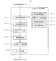
- a three-dimensional point cloud position data processing apparatus 100 shown in FIG. 1 includes a three-dimensional point cloud position data acquisition unit 101, a three-dimensional model creation unit 102, a similarity determination unit 103, a distance correlation data calculation unit 104, and a corresponding plane determination unit 105. , A corresponding surface alignment unit 106, a detailed alignment unit 107, a coordinate integration unit 108, an integrated 3D model creation unit 109, and an integrated image creation unit 110.
- the 3D point cloud position data acquisition unit 101 acquires 3D point cloud position data from the laser scanner described above.
- 3D point cloud position data related to the same measurement object acquired at two different viewpoints is input to the 3D point cloud position data acquisition unit 101.
- a mode in which the 3D point cloud position data acquisition unit 101 calculates the 3D point cloud position data based on the output of the laser scanner is also possible.
- the 3D point cloud position data processing apparatus 100 includes a 3D model creation unit 102.
- the three-dimensional model creation unit 102 calculates a non-surface region, removes the non-surface region, labeling processing, calculates a feature portion such as a contour line, creates a three-dimensional model composed of the contour line, and operations related thereto I do.
- the three-dimensional model is an image obtained by visualizing the three-dimensional structure of the measurement object in which the outline of the measurement object is expressed as a diagram.
- the outline is an outline that forms the outline of the measurement object, which is necessary for visually grasping the appearance of the measurement object. Specifically, a bent portion or a portion where the curvature is rapidly reduced becomes a contour line.
- the contour line is not limited to the outer contour part, but the edge part that characterizes the protruding part of the convex part, or the edge that characterizes the concave part (for example, the part of the groove structure).
- the part of is also the target.
- a so-called diagram can be obtained from the contour line, and an image can be displayed so that the appearance of the object can be easily grasped.
- the three-dimensional model includes not only the above-described line information but also information on points that are characteristic portions when the appearance of the measurement object is visually grasped. It is also possible to represent a three-dimensional model as a polyhedron composed of labeled surfaces.
- FIG. 2 shows a block diagram of the three-dimensional model creation unit 102.
- the three-dimensional model creation unit 102 includes a non-surface region calculation unit 201, a non-surface region removal unit 202, a surface labeling unit 203, a contour line calculation unit 204, a two-dimensional edge calculation unit 205, and an edge integration unit 206.
- a non-surface region calculation unit 201 includes a non-surface region calculation unit 201, a non-surface region removal unit 202, a surface labeling unit 203, a contour line calculation unit 204, a two-dimensional edge calculation unit 205, and an edge integration unit 206.
- the non-surface region calculation unit 201 includes a local region acquisition unit 201a that acquires a local region, a normal vector calculation unit 201b that calculates a normal vector of the local region, a local curvature calculation unit 201c that calculates a local curvature of the local region, A local plane calculation unit 201d that calculates a local plane to be fitted to the region is provided.
- the local area acquisition unit 201a acquires, as a local area, a square area (grid-like area) whose side is about 3 to 7 pixels around the target point based on the three-dimensional point cloud position data.
- the normal vector calculation unit 201b calculates a normal vector of each point in the local region acquired by the local region acquisition unit 201a. In the process of calculating the normal vector, attention is paid to the three-dimensional point cloud position data in the local region, and the normal vector of each point is calculated. This process is performed for all three-dimensional point cloud position data. That is, the three-dimensional point cloud position data is divided into countless local regions, and the normal vector of each point is calculated in each local region.
- the local curvature calculation unit 201c calculates the variation (local curvature) of the normal vector in the above-described local region.
- the average (mNVx, mNVy, mNVz) of the intensity values (NVx, NVy, NVz) of the three-axis components of each normal vector is obtained in the local region of interest.
- standard deviations (StdNVx, StdNVy, StdNVz) are further obtained.
- the square root of the square sum of the standard deviation is calculated as a local curvature (Local (Curveture: crv) (Equation 1).
- the local plane calculation unit 201d obtains a local plane that is fitted (approximated) to the local region.
- an equation of the local plane is obtained from the three-dimensional coordinates of each point in the local region of interest.
- the local plane is a plane that is fitted to the local region of interest.
- the equation of the surface of the local plane to be fitted to the local region is calculated using the least square method. Specifically, a plurality of different plane equations are obtained, compared with each other, and a surface equation of the local plane to be fitted to the local region is calculated. If the local region of interest is a plane, the local plane and the local region match. The above processing is repeated so that all the three-dimensional point cloud position data are targeted while sequentially shifting the local area, and the normal vector, local plane, and local curvature in each local area are obtained.
- the non-surface area removing unit 202 performs processing for removing points in the non-surface area based on the normal vector, local plane, and local curvature in each local area obtained above. That is, in order to extract a surface (a plane and a curved surface), a portion (non-surface region) that can be determined not to be a surface in advance is removed.
- the non-surface region is a region that is neither a plane nor a curved surface, but may include a curved surface with a high curvature depending on the following threshold values (1) to (3).
- the non-surface area removal unit 202 removes the calculated 3D point group position data of the non-surface area from the 3D point group position data acquired by the 3D point group position data acquisition unit 101.
- the non-surface area removal process can be performed using at least one of the following three methods.
- the determination by the following methods (1) to (3) is performed for all the above-mentioned local regions, and the local region determined as the non-surface region by one or more methods is configured as the non-surface region. Extract as a local region. Then, the 3D point cloud position data relating to the points constituting the extracted non-surface area is removed.
- a portion having a high local curvature The above-described local curvature is compared with a preset threshold value, and a local region having a local curvature exceeding the threshold value is determined as a non-surface region. Since the local curvature represents the variation of the normal vector at the point of interest and its peripheral points, the value is small for a surface (a flat surface and a curved surface with a small curvature), and the value is large for a surface other than a surface (non-surface). Therefore, if the local curvature is larger than a predetermined threshold, the local region is determined as a non-surface region.
- a local region determined as a non-surface region by one or more methods is extracted as a local region constituting the non-surface region. Then, the 3D point cloud position data relating to the points constituting the extracted local region is removed from the 3D point cloud position data to be calculated.
- the non-surface area is removed as described above. Since the removed 3D point cloud position data may be used in later processing, it is stored in an appropriate storage area so that it can be identified from the 3D point cloud position data that has not been removed. To make it available for later use.
- the surface labeling unit 203 is an example of a surface extraction unit.
- the surface labeling unit 203 performs surface labeling on the 3D point cloud position data from which the 3D point cloud position data of the non-surface area is removed based on the continuity of normal vectors. Specifically, if the angle difference between the normal vector of a specific point of interest and an adjacent point is less than a predetermined threshold, the same label is attached to those points. By repeating this operation, the same label is attached to a continuous flat surface and a continuous gentle curved surface, and these can be identified as one surface.
- the label is a plane or a curved surface with a small curvature by using the angle difference between the normal vectors and the standard deviation of the three-axis components of the normal vectors. Identification data for identifying the fact is associated with each label.
- the label (surface) with a small area is removed as noise.
- This noise removal may be performed simultaneously with the surface labeling process.
- the number of points of the same label (the number of points constituting the label) is counted, and a process of canceling the label having the number of points equal to or less than a predetermined value is performed.
- the same label as the nearest surface (closest surface) is given to the point having no label at this time. As a result, the already labeled surface is expanded.
- the equation of the surface with the label is obtained, and the distance between the surface and the point without the label is obtained. If there are a plurality of labels (surfaces) around a point where there is no label, the label with the shortest distance is selected. If there is still a point with no label, the threshold values for non-surface area removal, noise removal, and label expansion are changed, and related processing is performed again. For example, in non-surface area removal, the number of points to be extracted as non-surface is reduced by increasing the threshold value of local curvature. Alternatively, in label expansion, by increasing the threshold of the distance between a point without a label and the nearest surface, more labels are given to the point without a label.
- the labels are integrated if they are the same.
- the same label is attached to the surfaces having the same position or orientation. Specifically, by comparing the position and orientation of the normal vector of each surface, the same non-continuous surface is extracted and unified to the label of any surface. The above is the function of the surface labeling unit 203.
- the amount of data to be handled can be compressed, so that the processing of the 3D point cloud position data can be accelerated.
- the required amount of memory can be saved.
- the contour calculation unit 204 calculates (estimates) the contour based on the three-dimensional point cloud position data of the adjacent surfaces.
- the contour line calculation unit 204 obtains an intersection line between adjacent surfaces sandwiching a non-surface region therebetween, and performs a process of using this as a contour line.
- a method of approximating the non-planar region with a plurality of local planes by fitting a local plane to a non-planar region between adjacent surfaces and connecting a plurality of local planes may be employed. This can be regarded as an approximation of a non-planar region by a polyhedron composed of a plurality of local planes.
- the local planes are connected from the adjacent surfaces, and the line of intersection between the adjacent local planes is calculated as the contour line.
- the two-dimensional edge calculation unit 205 Based on the intensity distribution of the reflected light from the object, the two-dimensional edge calculation unit 205 corresponds to a segmented (segmented) surface using a known edge extraction operator such as Laplacian, Pleuwit, Sobel, Canny, etc. An edge is extracted from the area of the two-dimensional image to be processed. In other words, since the two-dimensional edge is recognized by the difference in shading in the surface, the difference in shading is extracted from the information on the intensity of the reflected light, and by setting a threshold value in the extraction condition, the border between the shading is used as an edge. Extract.
- a known edge extraction operator such as Laplacian, Pleuwit, Sobel, Canny, etc.
- the edge is extracted as a two-dimensional edge. That is, it is determined whether or not a point constituting the edge extracted on the two-dimensional image is on the segmented surface, and if it is determined that the point is on the surface, it is set as the two-dimensional edge.
- the contour calculated by the contour calculating unit 204 and the two-dimensional edge calculated by the two-dimensional edge calculating unit 205 are integrated. This process is performed in the edge integration unit 206. Thereby, edge extraction based on the three-dimensional point cloud position data is performed. By extracting the edge, a line (contour line) constituting the appearance of the measurement object when the measurement object is visually recognized is extracted, and three-dimensional model data is obtained.
- FIG. 3 shows an example of a three-dimensional model.
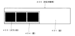
- FIGS. 3A and 3B show three-dimensional models of measurement objects 400 and 400 ′ (in this case, an example of a one-story building) from different viewpoints.
- symbol 409 is a glass surface
- the 3D point cloud position data processing apparatus 100 receives 3D point cloud position data measured at two different viewpoints. Therefore, the three-dimensional model creation unit 102 creates a three-dimensional model obtained from two different viewpoints as illustrated in FIG. As shown in FIG. 3, the two three-dimensional models are obtained by converting the same measurement object into data and expressing it as a diagram. The three-dimensional model obtained by the three-dimensional model creating unit 102 at this stage Since the model does not associate (position) the 3D point cloud position data obtained from the two viewpoints, the correspondence between them is not clear. In this sense, in FIG. 3, the same measurement object, but different measurement objects 400 and 400 ′ are given to the measurement object represented as a three-dimensional model.
- the similarity determination unit 103 performs the following processing.
- the three-dimensional model creation unit 102 creates a three-dimensional model viewed from two different viewpoints.
- extraction of the surfaces constituting the measurement object is performed. That is, as shown in FIG. 3, the measurement object is grasped as a set of a plurality of faces (polyhedron), and a three-dimensional model is created based on the contour information.
- the similarity determination unit 103 determines the similarity of the surfaces constituting the two three-dimensional models obtained from different viewpoints. That is, the degree of similarity between the specific surface of the first three-dimensional model and the specific surface of the second three-dimensional model is determined.
- n 4
- the upper four surfaces 401, 402, 403, 404 among the surfaces constituting the three-dimensional model 400 are extracted.
- the upper four surfaces 405, 406, 407, and 408 in the surfaces constituting the three-dimensional model 400 ' ⁇ ⁇ ⁇ of the measurement object are extracted.
- the shape similarity (matching) between the first group surfaces 401, 402, 403, and 404 and the second group surfaces 405, 406, 407, and 408 is obtained by calculation.
- the width of the target first group surface is W 1
- the height is H 1
- the width of the second group surface is W 2
- the height is H 2.
- the similarity S is calculated.
- the distance correlation data calculation unit 104 is an example of a relative positional relationship calculation unit that calculates a relative positional relationship between the surface of interest and another surface.
- the distance correlation data calculation unit 103 performs processing for obtaining a more detailed similarity for the top two combinations based on the results illustrated in Tables 1 and 2.
- Table 1 and Table 2 combinations of the surface 401 and the surface 405, the surface 401 and the surface 406, the surface 403 and the surface 407, and the surface 403 and the surface 408 are candidates with high similarity.
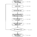
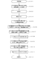
- FIG. 4 is a flowchart illustrating an example of processing performed in the distance correlation data calculation unit 104.
- the attention surface is first selected (step S102).
- the attention surface is selected from candidates determined to have high similarity by the similarity determination unit 103.
- the surface 401 is selected as the attention surface will be described.
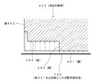
- FIG. 5 is a conceptual diagram for explaining the contents of processing performed in the distance correlation data calculation unit 104.
- FIG. 5 shows an example in which the surface 401 is selected as the attention surface.
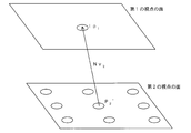
- the projection setting surface 500 is set on the measurement space based on the surface 401 (step S103).
- the projection setting surface 500 shares the center of gravity with the surface 401 when viewed from the normal direction of the surface 401 and has the same normal vector.
- the projection setting surface 500 is a surface whose size is expanded to a range of 5 m from the end of the surface 401, and is set at a position 5 m in front of the surface 401.
- the position of the projection setting surface 500 in the normal direction may be not the front side of the surface 401 but the back side thereof. It is also possible to match the positions of the projection setting surface 500 and the surface 401 in the normal direction.
- the normal vector of the projection setting surface 500 and the normal vector of the surface 401 can be in a specific angular relationship instead of the same direction.
- the size of the projection setting surface 500 is a dimension that is larger than the surface 401 as described above so that other surfaces around the surface 401 can be projected. This dimension is not limited to the above 5 m, and may be another value.
- each of the plurality of surfaces constituting the measurement object 400 is projected onto the projection setting surface 500. At this time, the projection is performed in the normal direction of the projection setting surface 500.
- the plurality of surfaces constituting the measurement target object 400 to be projected are not limited to those shown in FIGS. 3A and 3B, and are labeled in the processing in the three-dimensional model creation unit 102. To all aspects. In order to reduce the amount of calculation, a threshold is set for the number of point groups constituting the surface, and a surface composed of a predetermined number of point groups or more (that is, a surface having a specified area or more). Alternatively, the above processing may be performed.
- step S104 the distance between each surface at a plurality of positions set in a lattice shape and the projection setting surface 500 is calculated (step S104). This distance is calculated in the normal direction of the projection setting surface 500 (the normal direction of the surface 401).
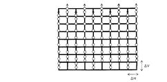
- the interval (resolution) of the lattice is set to 0.05 m.
- the distance between the overlapping surfaces in the normal direction is calculated at each of the set grid points. Specifically, considering the normal direction of the projection setting surface, the distance between the projection setting surface 500 and the surface 401 at each lattice point where the projection setting surface 500 and the surface 401 overlap, the projection setting The distance between the projection setting surface 500 and the surface 404 at each lattice point where the surface 500 and the surface 404 overlap is calculated. Further, since the surface 402 and the surface 403 are perpendicular to the projection setting surface 500, the distance of the portion closest to the projection setting surface 500 is calculated. By calculating the distance between the projection setting surface 500 and each surface at each grid point of the projection measurement surface 500, the positional relationship between the surface 401 of interest and the other surfaces is three-dimensionally. Somehow is grasped quantitatively.
- step S105 When the projection setting surface 500 at each grid point and the distance between each surface are calculated, those exceeding a predetermined value set in advance are excluded (step S105). This is to eliminate errors and useless calculations.
- matrix data is obtained in which the distance values between the projection setting surface 500 and each surface (the surface 401 and other surfaces surrounding it) in the normal direction of the projection setting surface 500 are distributed in a grid pattern.
- This matrix data becomes a correlation data group indicating the positional relationship in the three-dimensional space between the surface 401 and the other surface of the measurement object 400.
- This correlation data group is data in which distance values between the projection setting surface 500 and each surface at each lattice point are distributed in a matrix. Table 3 shows an example of this correlation data group.
- Z mn is the distance between the projection setting plane 500 and each plane.
- Z mn includes the distance between the projection setting surface 500 and the target surface 401 and the distance between the projection setting surface 500 and a plurality of other surfaces around the target surface 401. include.
- the correlation data group in Table 3 shows that the three-dimensional relative positional relationship between the surface 401 (target surface) constituting the measurement object 400 and the other surfaces constituting the measurement object 400 is the projection setting surface 500. It is expressed as a distribution state of the distance between.
- the correlation data group illustrated in Table 3 shows the positional relationship between the target plane and other planes in the depth direction and the two-dimensional distance in the depth direction between the projection setting planes. It can be said that it is a data group quantitatively evaluated as a general distribution state. With the correlation data group illustrated in Table 3, it is possible to quantitatively evaluate the positional relationship between the target surface and another surface in a three-dimensional manner.
- the distribution state of the distance from the projection setting surface 500 for each lattice point shown in Table 3 to the surface 401 constituting the measurement object 400 and other surfaces around it is the three-dimensional of the surface 401 of the measurement object 400. It is strongly correlated with the position, and becomes a unique data group that can specify the three-dimensional position of the surface 401 on the measurement object 400. That is, in the case of FIG. 3A and FIG.
- the matrix data in which the distance in the depth direction between the surface 401 and the surfaces 402, 403, 404 is recorded at each lattice point on the projection setting surface 500 is This is unique to the surface 401 that characterizes the three-dimensional position of the surface 401 in the measurement object 400 having a three-dimensional shape, and the possibility that the same matrix data is obtained on the other surface is extremely low and is not practical. be equivalent to. This tendency becomes more prominent as the shape of the measurement object 400 becomes more complicated and as the asymmetry becomes larger.
- a distance image relating to the target surface (in this case, the surface 401) is created (step S106).
- the distance image is an image in which a difference in distance between the projection setting surface 500 calculated for each lattice point and each surface constituting the measurement object 400 overlapping in the normal direction is displayed as a difference in density or the like. It is. That is, at this stage, at each lattice point on the projection setting surface 500, the distance between the projection setting surface 500 and the surface projected onto the projection setting surface 500 is obtained. A distance image is obtained by imaging the distance value at each grid point as pixel information. With the distance image, the three-dimensional position of the surface of interest in the measurement object can be evaluated.
- the distance image is convenient and can be handled in the same manner as the image information in the calculation. Therefore, the distance image is merely called an image, and it is not necessary to actually generate image data.
- FIG. 6 shows an example of a distance image.
- FIG. 6 shows a distance image corresponding to the situation of FIG.
- the surface closest to the projection setting surface 500 in FIG. 5 is shown in white, and then the surface close to the projection setting surface 500 is shown in diagonal lines.
- the glass surface 409 is not labeled as a surface because accurate three-dimensional point cloud position data cannot be obtained. Further, the surfaces 402 and 403 in FIG. 5 are not shown.
- step S106 After creating the distance image in step S106, it is determined whether or not there is a candidate for an attention surface other than the attention surface focused here (step S107). If there are other candidates for the attention surface, The processing after step S102 is repeated, and if there is no other candidate for the attention surface, the processing is terminated (step S108). In this way, the distance image illustrated in FIG. 6 is created for all the surfaces narrowed down by the determination by the similarity determination unit 103 of FIG.
- the distance image with the surface 401 as the attention surface A distance image with the surface 403 as the attention surface, a distance image with the surface 405 as the attention surface, a distance image with the surface 406 as the attention surface, a distance image with the surface 407 as the attention surface, and a distance image with the surface 408 as the attention surface Create
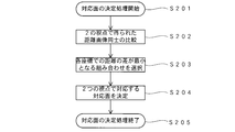
- the corresponding surface determination unit 105 Based on the distance image acquired by the distance correlation data calculation unit 104, the corresponding surface determination unit 105 includes the surfaces 401, 402, 403, and 404 at the first viewpoint in FIG. 3A and the first image in FIG. A process of searching for a corresponding surface between the surfaces 405, 406, 407, and 408 at the second viewpoint is performed. Corresponding surface determination unit 105 compares one of the distance images at the first viewpoint and one of the distance images at the second viewpoint, and performs processing that sets the smallest difference as a surface corresponding to the two viewpoints. Do. That is, the plurality of distance images obtained from the viewpoint of FIG. 3A and the plurality of distance images obtained from the viewpoint of FIG. 3B are individually compared to find the most similar distance image pair. Processing is performed in which the target surface in the pair of distance images is a corresponding surface.
- FIG. 7 is a flowchart illustrating an example of processing performed in the corresponding surface determination unit 105.
- step S201 the two distance images are compared in a state where the positions of the centers of gravity of the distance images are matched (step S202).
- step S202 the distance values at the same coordinate point (lattice point) are compared, and RMS, which is the average of the differences, is calculated.
- RMS is calculated by the following equation (3).
- FIG. 8 is a conceptual diagram illustrating P i and Q i in the above equation (3).
- FIG. 8 shows a point Q 1 at a position corresponding to a distance value at a specific grid point on the first distance image and a position corresponding to a distance value at a specific grid point on the second distance image.
- a point P 1 is shown.
- RMS is calculated by the above equation (3).
- RMS 0 ideally.
- the RMS is calculated on all face pairs of possible combinations.
- Table 4 shows an example of the RMS calculation result. As shown in Table 4, the RMS values related to the distance images having the corresponding surfaces as the attention surface as viewed from the two viewpoints are small, and the RMS values related to the distance images having the non-corresponding surfaces as the attention surfaces are large.
- step S203 a combination of values with the smallest calculated RMS is selected.
- a combination having the surface 401 and the surface 405 with the smallest RMS as the target surface is selected as a corresponding surface combination.
- the combination of the attention surfaces that minimizes the RMS is determined as the corresponding surface (step S204), and the processing performed by the corresponding surface determination unit 105 ends (step S205).
- the small RMS means that the similarity between the two distance images to be compared is high.
- the high similarity between the two distance images means that the similarity of the correlation data group of the distances relative to the other surfaces related to the two target surfaces of interest is high. This means that the specificities of the positional correlation with respect to other surfaces are similar.
- the correlation data group indicating the positional relationship in the three-dimensional space between the target surface and another surface in the measurement object can be used as a concept for specifying the surface. Therefore, the correlation data group selected from the plane at the first viewpoint and the correlation data group selected from the plane at the second viewpoint are compared, and the plane 401 is searched for the smallest difference. And the corresponding surface can be found from two viewpoints as indicated by the surface 405.
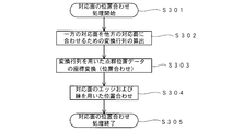
- FIG. 9 is a flowchart illustrating an example of processing performed by the corresponding surface determination unit 105.
- a conversion matrix necessary for matching one corresponding surface with the other corresponding surface is calculated (step S302).
- a transformation matrix is calculated for rigid body transformation that matches the position of the center of gravity of the surface 401 and the position of the center of gravity of the surface 405, and further aligns the normal directions of the two surfaces. It is. For example, consider the case where the surface 405 matches the surface 401.
- T c is a transformation matrix that expresses the parallel movement of the surface 405 and R c is a rotation matrix that rotates the surface 405, which is necessary for making the surface 405 coincide with the surface 401.
- step S303 By performing this rigid transformation on all the 3D point cloud position data obtained at the second viewpoint, the 3D point cloud position data obtained from the first viewpoint and the second viewpoint were obtained.
- a rough alignment with the three-dimensional point cloud position data is performed (step S303). By performing this alignment, the correspondence between the 3D point cloud position data obtained from the first viewpoint and the 3D point cloud position data obtained from the second viewpoint is clarified.
- the original point cloud position data can be handled in the same coordinate system.
- the two-dimensional point group position data obtained from two different viewpoints are aligned, that is, the three-dimensional point group position data obtained at the first viewpoint and the second
- the correspondence with the 3D point cloud position data obtained at the viewpoint can be obtained.
- a slight shift in the position of the center of gravity may occur due to the influence of noise and measurement errors.
- the contours (edge portions) and edges (corner portions) of the corresponding surfaces are matched.
- the correction value for correcting the transformation matrix of Equation 4 is calculated. Since this process is almost complete, it is not necessary to target a huge amount of 3D point cloud position data, and can be performed in a short time.
- the contours and edge positions of the surfaces 401 and 405 are parameters that characterize the surface 401 and the surface 405. By aligning the positions, the accuracy of the alignment of the two corresponding surfaces can be further increased. This processing may be performed by the corresponding surface determination unit 105 or may be performed by the corresponding surface positioning unit 106.
- the alignment of the corresponding surface in the alignment unit 106 is an alignment using one surface as a foothold, and thus a certain amount of error often occurs. Therefore, based on the result of the processing in the alignment unit 106 of the corresponding surface, the detailed alignment unit 107 performs more detailed alignment, and the alignment accuracy is improved.
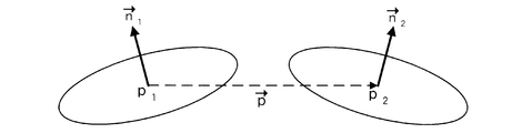
- FIG. 10 is a conceptual diagram illustrating coplanar conditions.
- normal vectors of two candidate planes are set as n 1 and n 2
- points on the two planes are set as p 1 and p 2
- a vector connecting the two points is set as p.
- one of the two surfaces is a surface based on the 3D point cloud position data obtained from the first viewpoint
- the other surface is based on the 3D point cloud position data obtained from the second viewpoint.
- Equation 5 is an expression for determining the co-plane.
- d when d is smaller than 1, it is determined that the two surfaces to be compared are on the same plane.
- two surfaces are overlapped by 75% or more, it is determined that the two surfaces correspond to each other.
- a determination is made for all surfaces whether they are on the same plane and whether they are on the same plane and overlap.
- the distance d between the corresponding surface and the point is calculated as shown in FIG.
- the intersection of the vector extending in the direction of the normal Nv 2 of the surface from the point P 2 ′ (rigidly transformed by Equation 4) belonging to the surface of the second viewpoint and the corresponding surface of the first viewpoint is Ip 1
- the distance d is expressed by the following formula 6.
- FIG. 11 shows the distance from one point on the second surface, but this calculation is performed for all points on the corresponding surface belonging to the second viewpoint, and the sum is regarded as an error. Then, this error is minimized.
- this error is minimized using a multidimensional downhill simplex method.
- an error evaluation function E (Expression 7) representing the sum of distances is introduced.
- the rigid body transformation parameters, R d and T d are obtained so that E is minimized.
- the simplex reflection, enlargement, and reduction coefficients used in the calculation are 1.0, 0.5, and 2.0, respectively.
- the following formula 8 is used for convergence determination.
- Equation 7 is calculated using parameters T h , R h , T 1 , R 1 having the maximum and minimum errors, and a function f for calculating an error using them, from the conversion parameters obtained during the iterative calculation.
- the This iterative calculation is judged to have converged when the condition of Equation 8 is satisfied, and the calculation is stopped.
- e 1.0-12 is set as the convergence condition. Even if it does not converge, the upper limit of the iterative calculation is set to 5000 times.
- Alignment in the detailed alignment unit 107 can be performed using a known ICP (Iterative Closest Point) algorithm in addition to the above method.
- ICP Intelligent Closest Point
- the corresponding surface alignment unit 106 since a certain degree of alignment is performed by the corresponding surface alignment unit 106, it is not necessary to perform comparison point selection, corresponding point search, and unnecessary point removal processing in the ICP algorithm. Therefore, only error minimization calculation is performed, and high calculation accuracy can be obtained with a small calculation amount. In order to minimize the error, it is possible to use the steepest descent method or Newton method in addition to the downhill simplex.
- the ICP algorithm is used, the surfaces are compared with each other, and association is performed by iterative calculation.
- the coordinate integration unit 108 in FIG. 1 describes the three-dimensional point cloud position data obtained from the first viewpoint based on the rigid body transformation parameters obtained in the corresponding surface positioning unit 106 and the detailed positioning unit 107.
- the first coordinate system and the second coordinate system describing the three-dimensional point group position data obtained from the second viewpoint are integrated. This is done, for example, by converting one coordinate system to the other coordinate system. By doing so, it becomes possible to handle the two-dimensional three-dimensional point cloud position data in one coordinate system.
- the 3D point cloud position data obtained from the first viewpoint in FIG. 3A and the 3D point cloud position data obtained from the second viewpoint in FIG. 3B are integrated. Can be handled.
- the integrated 3D model creation unit 109 creates a 3D model based on 3D point cloud position data obtained from two different viewpoints.
- the three-dimensional model obtained in this case is obtained by complementing a portion that is occluded from one viewpoint with three-dimensional point cloud position data from the other viewpoint.
- the integrated image creation unit 110 generates image data of the 3D model created by the 3D model creation unit 109. By sending the image data to a display device such as a liquid crystal display and causing the display to be performed, for example, a three-dimensional model image display as shown in FIG. 3 is performed.
- the 3D point cloud position data obtained from the first viewpoint in FIG. 3A and the 3D point cloud position data obtained from the second viewpoint in FIG. When the three-dimensional model obtained in (2) is rotated to the state viewed from the first viewpoint, it looks like FIG. 3 (A), and when it is rotated and viewed from the viewpoint of FIG. 3 (B), The display shown in FIG. At this time, the problem that the surface 406 invisible from the first viewpoint and the surface 402 invisible from the second viewpoint become occluded does not occur.
- the occlusion does not occur in the portion visible from at least one of FIGS. 3A and 3B even if the 3D model is rotated, and the display is performed in the same manner as the 3D CAD data. Can be obtained.
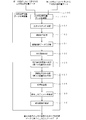
- FIG. 12 is a flowchart showing an example of the operation of the three-dimensional point cloud position data processing device 100.
- the 3D point cloud position data acquisition unit 101 in FIG. 1 acquires 3D point cloud position data obtained from two different viewpoints (step S402).
- processing based on the three-dimensional point cloud position data in the three-dimensional model creation unit 102 in FIG. 1 is performed, and in the process, surface labeling is performed and the surface of the measurement object is extracted.
- This process is performed for each of two groups of three-dimensional point cloud position data obtained from two viewpoints (step S403).
- step S404 similarity determination processing is performed based on the extracted surface data (step S404), and based on the result, a set of surfaces with high similarity is extracted (step S405).
- This process is performed in the similarity determination unit 103 in FIG.
- distance correlation data for other surfaces is calculated, and a distance image is created (step S406).
- This processing is performed in the distance correlation data calculation unit 104 in FIG. 1 according to the procedure shown in FIG. 4, for example.
- step S406 the distance images created in step S406 are compared (step S407), and the combination that minimizes the RMS based on the difference in distance data at each coordinate is a surface corresponding to the surfaces obtained from two different viewpoints ( (Corresponding surface) is determined (step S408).
- This processing is performed by the corresponding surface determination unit 105 in FIG. 1 according to the procedure shown in FIG. 7, for example.
- step S409 When the corresponding surface is determined, the corresponding surfaces are aligned, and the correspondence between the coordinates of the corresponding surface at one viewpoint and the coordinates of the corresponding surface at the other viewpoint is obtained (step S409).
- This processing is performed in the corresponding surface alignment unit 106 in FIG. 1 according to the procedure shown in FIG. 9, for example.
- step S410 more detailed alignment is performed by aligning surfaces other than the corresponding surfaces. This processing is performed in the detail matching unit 107 in FIG. 1 according to the procedure described with reference to FIGS. 10 and 11, for example.
- step S410 After performing the detailed alignment in step S410, the correspondence between the three-dimensional point cloud position data obtained from two different viewpoints is obtained, and the coordinate system that handles the two three-dimensional point cloud position data is obtained. To do. Then, an integrated three-dimensional model is created using this coordinate system (step S411), and the process is terminated (step S412).
- the projection setting surface 500 As an element characterizing the surface 401 included in a plurality of surfaces constituting the measurement object, the projection setting surface 500 having the same normal vector as the surface 401 is set in the measurement space, and other surfaces including the surface 401 are projected. Projected onto the setting plane 500. At this time, the distance between each surface and the projection setting surface 500 is calculated from the lattice points set on the projection setting surface 500, and the matrix data is used as a distance image characterizing the surface 401. This distance image is created on another surface and also on the surface viewed from another viewpoint. Then, the distance images at the two viewpoints are compared, and the combination of the surfaces from which the set of distance images having the smallest difference is obtained is set as the corresponding surface at the two viewpoints.
- the correlation data group as exemplified in Table 3 is unique to the target surface, and is very highly distinctive to characterize the target surface. Therefore, by searching for a combination of correlation data groups with the smallest difference, The corresponding surface can be found with high accuracy.
- the amount of calculation can be reduced and the accuracy can be maintained.
- the attention surface may be characterized by calculating distances from the center of gravity of the attention surface to a plurality of positions on another target surface and acquiring them as matrix data like the distance image in FIG. .
- the three-dimensional positional relationship between the target surface and other surfaces can be quantitatively grasped, thereby characterizing the target surface, and the target surface can be distinguished from other surfaces in the measurement object. It becomes.
- the case where the number of viewpoints is two has been described as an example of a basic case, but by further integrating information from viewpoints different from the third viewpoint, the fourth viewpoint, etc., occlusion The accuracy of the obtained three-dimensional model can be further reduced.
- main 3D point cloud position data is obtained from a laser scanner
- the corresponding plane is calculated for the three-dimensional point cloud position data obtained from the laser scanner and the three-dimensional point cloud position data obtained from the stereoscopic photograph image.
- Second Embodiment As a method of searching for a corresponding surface using a relative positional relationship between a target surface and another surface, the target surface and the other surface in the measurement object described in the first embodiment are used. The method using the correlation data group indicating the positional relationship in the three-dimensional space is optimal, but there are other methods.
- a method for searching for a corresponding surface using the relative positional relationship between the attention surface and another surface will be described.
- a method for detecting the corresponding surface a method for comparing the parameters related to the three-dimensional shape of the measurement object and detecting the corresponding surface based on the matching will be described.
- the three-dimensional point model creation unit 102 in FIG. 1 performs processing that allows the appearance of the measurement object to be handled as a set of a plurality of surfaces based on the three-dimensional point cloud position data.
- each surface is treated as a label that can be distinguished from the other.
- the label has surface position and surface orientation data.
- the position of the label is specified by, for example, the three-dimensional coordinates of the center of gravity of the surface.
- FIG. 13 is a conceptual diagram illustrating a matching method using labels.
- FIG. 13A conceptually shows the acquisition of 3D point cloud position data from the first viewpoint for the measurement object and further acquisition of 3D point cloud position data from the second viewpoint. Is described as a simplified model.
- the measurement object is the first surface to which the label 1 is applied, the second surface to which the label 2 is applied, the third surface to which the label 3 (label 1 ′) is applied, and the label 4 (label). 2 ') is provided, the fifth surface is provided with a label 3', and the sixth surface is provided with a label 4 '.
- FIG. 13B shows a labeled measurement object model (measurement object model constituted by a label) obtained from the first viewpoint.
- the labeled model of the measurement object is a three-dimensional model, but here, a two-dimensional simplified model is shown.
- FIG. 13C shows a model of the measurement object that is labeled and obtained from the second viewpoint.
- the labeling model of FIG. 13B and the labeling model of FIG. 13B Before the alignment (that is, the identification of the correspondence) between the three-dimensional point cloud position data obtained from the two viewpoints, the labeling model of FIG. 13B and the labeling model of FIG. The correspondence is not clear.
- the labeling model in FIG. 13B and the labeling in FIG. Explain the method to clarify the correspondence between models.
- the label is characterized by information on the orientation of the labeled surface and its center of gravity. Therefore, in the case of FIG. 13, the correlation between label 1 and label 2, the correlation between label 2 and label 3, and the correlation between label 3 and label 4 specify the relationship between the relative position and orientation of adjacent labels. It becomes clear by doing. Then, the shape of the labeling model shown in FIG. 13B is specified by the correlation between adjacent labels. Similarly, the shape of the labeling model shown in FIG. 13C is specified by the correlation between adjacent labels.
- FIG. 14 shows a specific label as a reference
- the horizontal axis indicates the angle of another label with respect to the specific label
- the vertical axis indicates the number of three-dimensional point groups constituting the label at the angle.
- An example of a histogram is shown.
- the vertical axis of the histogram can be grasped as a parameter corresponding to the area of the surface.
- a histogram based on each of the labels obtained from the first viewpoint shown in FIG. 13B and a reference of each of the labels obtained from the second viewpoint shown in FIG. Create a histogram. This histogram shows the correlation between adjacent labels.
- FIG. 14 shows a case where the histogram of label 3 obtained from the first viewpoint is similar to the histogram of label 1 'obtained from the second viewpoint. Accordingly, in this case, the label 3 in FIG. 13B and the label 1 ′ in FIG. 13C are selected as corresponding surfaces. Then, although not shown in FIG. 14, by performing a similar histogram comparison operation, label 4 in FIG. 13B and label 2 ′ in FIG. 13C are selected as corresponding surfaces. The In this way, the correspondence relationship between the label obtained from the first viewpoint and the label obtained from the second viewpoint as shown in FIG. Then, by obtaining this corresponding surface, as in the case of determining the corresponding surface using the distance image described with reference to FIGS. 5 to 7, between the three-dimensional models obtained from two different viewpoints. The corresponding surface can be determined.
- the portion of the distance correlation data calculation unit 104 is replaced with the processing unit that generates the histogram. Then, a corresponding histogram is selected by the corresponding surface determination unit 105 and processing for determining the corresponding surface is performed.
- the amount of data related to the label can be overwhelmingly small compared to the 3D point cloud position data. For this reason, the calculation based on the principle shown in FIG. 13 can dramatically increase the calculation speed as compared with the case of performing matching using the three-dimensional point cloud position data as it is.
- alignment by a method other than the method using the above-described histogram is possible.
- a portion matching the shape is searched for by a method such as stereo matching, and the corresponding surface is determined.
- the magnification is varied, and the parts of label 3 and label 4 having a common correlation And label 1 ′ and label 2 ′ overlap (see FIG. 13D), the corresponding surfaces can be found by using two labeling models.
- a method of narrowing down corresponding surface candidates by the method shown in the present embodiment and then determining the corresponding surface by the method of the first embodiment may be mentioned.
- a method of determining the corresponding surface by appropriately selecting the method of the first embodiment or the method of the present embodiment according to the shape of the measurement object is possible.
- a three-dimensional laser scanner having a function of processing three-dimensional point cloud position data will be described.
- a three-dimensional laser scanner irradiates a measurement object with distance measuring light (laser light) while scanning it, and performs a number of measurements on the measurement object from its own position based on the time of flight of the laser light. Measure the distance to the point.
- the three-dimensional laser scanner detects the irradiation direction (horizontal angle and elevation angle) of the laser beam, and calculates the three-dimensional coordinates of the measurement point based on the distance and the irradiation direction.
- the three-dimensional laser scanner acquires a two-dimensional image (RGB intensity at each measurement point) obtained by photographing the measurement object, and forms three-dimensional point group position data that combines the two-dimensional image and the three-dimensional coordinates. . Further, the three-dimensional laser scanner shown here has a function of performing the processing of the three-dimensional point cloud position data processing apparatus 100 described with reference to FIG.
- FIG. 15 and 16 are cross-sectional views showing the configuration of the three-dimensional laser scanner 1.
- the three-dimensional laser scanner 1 includes a leveling unit 22, a rotation mechanism unit 23, a main body unit 27, and a rotation irradiation unit 28.
- the main body 27 includes a distance measuring unit 24, a photographing unit 25, a control unit 26, and the like.
- FIG. 15 shows a state where only the rotary irradiation unit 28 is viewed from the side with respect to the cross-sectional direction shown in FIG.
- the leveling unit 22 has a base plate 29, and the rotation mechanism unit 23 has a lower casing 30.
- the lower casing 30 is supported on the base plate 29 at three points by a pin 31 and two adjustment screws 32.
- the lower casing 30 tilts with the tip of the pin 31 as a fulcrum.
- a tension spring 33 is provided between the base plate 29 and the lower casing 30 to prevent the base plate 29 and the lower casing 30 from separating from each other.
- two leveling motors 34 are provided inside the lower casing 30 .
- the two leveling motors 34 are driven by the control unit 26 independently of each other.
- the adjustment screw 32 is rotated via the leveling drive gear 35 and the leveling driven gear 36, and the amount of downward protrusion of the adjustment screw 32 is adjusted.
- An inclination sensor 37 (see FIG. 13) is provided inside the lower casing 30.
- the two leveling motors 34 are driven by the detection signal of the tilt sensor 37, whereby leveling is executed.
- the rotation mechanism 23 has a horizontal angle drive motor 38 inside the lower casing 30.
- a horizontal rotation drive gear 39 is fitted to the output shaft of the horizontal angle drive motor 38.
- the horizontal rotation drive gear 39 is meshed with the horizontal rotation gear 40.
- the horizontal rotation gear 40 is provided on the rotation shaft portion 41.
- the rotating shaft portion 41 is provided at the center portion of the rotating base 42.
- the rotating base 42 is provided on the upper portion of the lower casing 30 via a bearing member 43.
- the rotary shaft 41 is provided with, for example, a rotary encoder as the horizontal angle detector 44.
- the horizontal angle detector 44 detects a relative rotation angle (horizontal angle) of the rotation shaft portion 41 with respect to the lower casing 30.
- the horizontal angle is input to the control unit 26, and the control unit 26 controls the horizontal angle drive motor 38 based on the detection result.
- the main body 27 has a main body casing 45.
- the main body casing 45 is fixed to the rotating base 42.
- a lens barrel 46 is provided inside the main body casing 45.
- the lens barrel 46 has a rotation center concentric with the rotation center of the main body casing 45.
- the center of rotation of the lens barrel 46 is aligned with the optical axis 47.
- a beam splitter 48 as a light beam separating means is provided inside the lens barrel 46.
- the beam splitter 48 has a function of transmitting visible light and reflecting infrared light.
- the optical axis 47 is separated into an optical axis 49 and an optical axis 50 by a beam splitter 48.
- the distance measuring unit 24 is provided on the outer periphery of the lens barrel 46.
- the distance measuring unit 24 includes a pulse laser light source 51 as a light emitting unit. Between the pulse laser light source 51 and the beam splitter 48, a perforated mirror 52 and a beam waist changing optical system 53 for changing the beam waist diameter of the laser light are arranged.
- the distance measuring light source unit includes a pulse laser light source 51, a beam waist changing optical system 53, and a perforated mirror 52.
- the perforated mirror 52 has a role of guiding the pulsed laser light from the hole 52 a to the beam splitter 48, and reflecting the reflected laser light returned from the measurement object toward the distance measuring light receiving unit 54.
- the pulse laser light source 51 emits infrared pulse laser light at a predetermined timing under the control of the control unit 26.
- the infrared pulse laser beam is reflected by the beam splitter 48 toward the high / low angle rotating mirror 55.
- the elevation mirror 55 for high and low angles reflects the infrared pulse laser beam toward the measurement object.
- the elevation mirror 55 is rotated in the elevation direction to convert the optical axis 47 extending in the vertical direction into a projection optical axis 56 in the elevation direction.
- a condensing lens 57 is disposed between the beam splitter 48 and the elevation mirror 55 and inside the lens barrel 46.
- the reflected laser light from the object to be measured is guided to the distance measuring light receiving unit 54 through the high and low angle rotating mirror 55, the condenser lens 57, the beam splitter 48, and the perforated mirror 52. Further, the reference light is also guided to the distance measuring light receiving unit 54 through the internal reference light path.
- the three-dimensional laser scanner 1 is based on the difference between the time until the reflected laser light is received by the distance measuring light receiving unit 54 and the time until the laser light is received by the distance measuring light receiving unit 54 through the internal reference light path.
- the distance from the object to be measured (measurement target point) is measured.
- the ranging light receiving unit 54 is configured by a photoelectric change element such as a CMOS optical sensor, and also has a function of detecting the RGB intensity of the detected light.
- the photographing unit 25 includes an image light receiving unit 58 and functions as a camera.
- the image light receiving unit 58 is provided at the bottom of the lens barrel 46.
- the image light receiving unit 58 is configured by an array of a large number of pixels arranged in a plane, for example, a CCD (Charge-Coupled Device).
- the position of each pixel of the image light receiving unit 58 is specified by the optical axis 50. For example, assuming an XY coordinate with the optical axis 50 as the origin, a pixel is defined as a point of this XY coordinate.
- the rotary irradiation unit 28 is housed in the light projection casing 59.
- a part of the peripheral wall of the light projection casing 59 serves as a light projection window.
- a pair of mirror holder plates 61 are provided facing the flange portion 60 of the lens barrel 46.
- a rotation shaft 62 is stretched over the mirror holder plate 61.
- the high / low angle turning mirror 55 is fixed to the turning shaft 62.
- An elevation gear 63 is fitted to one end of the rotation shaft 62.
- An elevation angle detector 64 is provided on the other end side of the rotation shaft 62. The elevation angle detector 64 detects the rotation angle of the elevation angle rotation mirror 55 and outputs the detection result to the control unit 26.
- a driving motor 65 for high and low angles is attached to one side of the mirror holder plate 61.
- a drive gear 66 is fitted on the output shaft of the high / low angle drive motor 65.
- the drive gear 66 is meshed with an elevation gear 63 attached to the rotary shaft 62.
- the elevation motor 65 is appropriately driven by the control of the control unit 26 based on the detection result of the elevation detector 64.
- the sight sight gate 67 is used for roughly collimating the measurement object.
- the collimation direction using the sight sight gate 67 is a direction orthogonal to the direction in which the projection light axis 56 extends and the direction in which the rotation shaft 62 extends.
- a GPS antenna 81 is disposed on the upper part of the light projection casing 59. GPS information is acquired by the GPS antenna, and the GPS information can be used for calculations performed internally.
- FIG. 17 is a block diagram of the control unit. Detection signals from the horizontal angle detector 44, the elevation angle detector 64, the tilt sensor 37, and the GPS antenna 81 are input to the control unit 26.
- the control unit 26 receives an operation instruction signal from the operation unit 6.
- the control unit 26 drives and controls the horizontal angle drive motor 38, the elevation angle drive motor 65, and the leveling motor 34, and controls the display unit 7 that displays the work status, measurement results, and the like.
- An external storage device 68 such as a memory card or HDD can be attached to and detached from the control unit 26.
- the control unit 26 includes a calculation unit 4, a storage unit 5, a horizontal drive unit 69, a height drive unit 70, a leveling drive unit 71, a distance data processing unit 72, an image data processing unit 73, and the like.
- the storage unit 5 includes a sequence program, a calculation program, a measurement data processing program for executing measurement data processing, an image processing program for performing image processing, and a three-dimensional point, which are necessary for distance measurement and detection of elevation angle and horizontal angle.
- a program for extracting a surface from group position data and further calculating a contour line, an image display program for displaying the calculated contour line on the display unit 7, and a process related to reacquisition of three-dimensional point group position data are controlled.
- the storage unit 5 stores various data such as measurement data and image data.
- the horizontal drive unit 69 drives and controls the horizontal angle drive motor 38
- the elevation drive unit 70 controls the drive of the elevation angle drive motor 65
- the leveling drive unit 71 controls the leveling motor 34.
- the distance data processing unit 72 processes the distance data obtained by the distance measuring unit 24, and the image data processing unit 73 processes the image data obtained by the photographing unit 25.
- control unit 26 includes a GPS receiving unit 82.
- the GPS receiver 82 processes a signal from a GPS satellite received by the GPS antenna, and calculates coordinate data on the earth. This is the same as a normal GPS receiver. Position information obtained from the GPS is input to a three-dimensional point cloud position data processing unit 100 'described later.
- FIG. 18 is a block diagram of the calculation unit 4.
- the calculation unit 4 includes a three-dimensional coordinate calculation unit 74, a link formation unit 75, a grid formation unit 9, and a three-dimensional point group position data processing unit 100 '.
- the three-dimensional coordinate calculation unit 74 receives the distance data of the measurement target point from the distance data processing unit 72, and the direction data (horizontal angle and elevation angle) of the measurement target point from the horizontal angle detector 44 and the elevation angle detector 64. Is entered. Based on the input distance data and direction data, the three-dimensional coordinate calculation unit 74 determines the three-dimensional coordinates (orthogonal coordinates) of each measurement point with the position of the three-dimensional laser scanner 1 as the origin (0, 0, 0). calculate.
- the link forming unit 75 receives the image data from the image data processing unit 73 and the coordinate data of the three-dimensional coordinates of each measurement point calculated by the three-dimensional coordinate calculation unit 74.
- the link forming unit 75 forms 3D point group position data 2 in which image data (RGB intensity at each measurement point) and 3D coordinates are linked. That is, when focusing on a point on the measurement object, the link forming unit 75 creates a link in which the position of the point of interest in the two-dimensional image is associated with the three-dimensional coordinates of the point of interest. The associated data is calculated for all the measurement points, and becomes the three-dimensional point group position data 2.
- the link forming unit 75 outputs the above three-dimensional point cloud position data 2 to the grid forming unit 9.
- the grid forming unit 9 forms an equally spaced grid (mesh) and registers the point closest to the grid intersection. Or the grid formation part 9 correct
- FIG. 19 is a conceptual diagram showing three-dimensional point group position data in which the distance between points is not constant
- FIG. 20 is a conceptual diagram showing a formed grid.
- the average horizontal interval H 1 to N of each column is obtained, and the difference ⁇ H i, j of the average horizontal interval between columns is calculated, and the average is set as the horizontal interval ⁇ H of the grid (Equation 9 ).
- the vertical interval is calculated by calculating the distance ⁇ V NH between adjacent columns in each column in the vertical direction, and taking the average of ⁇ V NH in the entire image of the image sizes W and H as the vertical interval ⁇ V (Equation 10). Then, as shown in FIG. 20, a grid with the calculated horizontal interval ⁇ H and vertical interval ⁇ V is formed.
- a predetermined threshold is provided for the distance from the intersection to each point to limit registration.
- the threshold value is 1 ⁇ 2 of the horizontal interval ⁇ H and the vertical interval ⁇ V. It should be noted that all points may be corrected by applying a weight according to the distance from the intersection, such as a linear interpolation method or a bicubic method. However, when interpolation is performed, the point is not originally measured.
- the 3D point cloud position data obtained as described above is output to the 3D point cloud position data processing unit 100 '.
- the three-dimensional point cloud position data processing unit 100 ′ is a dedicated integrated circuit that performs the same operation as the three-dimensional point cloud position data processing device 100 described in the first embodiment, and includes an FPGA or the like. Further, the display of the image presented to the user in the operation of the three-dimensional point cloud position data processing unit 100 ′ is displayed on the display unit 7 which is a liquid crystal display.
- the coordinate data on the earth obtained from the GPS receiving unit 82 is input to the three-dimensional point cloud position data processing unit 100 ′.
- coordinates handled by the three-dimensional point cloud position data processing unit 100 ′ are linked to position data (for example, electronic map information) obtained from the GPS.
- position data for example, electronic map information
- the apparatus shown in FIGS. 15 and 16 uses the personal computer shown in the first embodiment.
- a three-dimensional laser scanner that can be used in combination with the three-dimensional point cloud position data processing apparatus 100 is obtained.
- a configuration in which the processing performed by the three-dimensional point cloud position data processing unit 100 ′ is performed in a distributed manner is possible.
- a configuration in which a part of the functions of the three-dimensional point cloud position data processing unit 100 ′ is performed by a server connected by a communication line is also possible.
- These configurations are understood as an example of the optical information processing system of the present invention.
- an image of a measurement object can also be reproduced based on point cloud data.
- three-dimensional point cloud position data is obtained by a laser scanner, data relating to the light intensity of reflected light from each point is obtained. Therefore, by treating the 3D point cloud position data as pixel data constituting the image of the object, the image of the measurement object can be reproduced based on the 3D point cloud position data. That is, an image of the measurement object can be obtained using a laser scanner instead of a photographing means such as a CCD or a CMOS image sensor. In this case, the image receiving unit 102 in FIG. 1 acquires image data based on the above-described principle based on the three-dimensional point cloud position data output from the laser scanner.
- the present invention can be used for a technique for measuring three-dimensional information.
- SYMBOLS 1 Three-dimensional laser scanner, 2 ... Three-dimensional point cloud position data, 22 ... Leveling part, 23 ... Rotation mechanism part, 24 ... Distance measuring part, 25 ... Imaging
- High / low angle gear 64 DESCRIPTION OF SYMBOLS: High / low angle detector, 65 ... High / low angle drive motor, 66 ... Drive gear, 67 ... Teru teru gate, 68 ... External storage device, 69 ... Horizontal drive unit, 70 ... High / low drive unit, 71 ... Leveling drive unit 72 ... Distance data processing unit 73 ... Image data processing unit 81 ... GPS antenna 82 ... GPS receiving unit 100 '... Three-dimensional point cloud position data processing unit
Landscapes
- Physics & Mathematics (AREA)
- General Physics & Mathematics (AREA)
- Engineering & Computer Science (AREA)
- Computer Vision & Pattern Recognition (AREA)
- Theoretical Computer Science (AREA)
- Length Measuring Devices By Optical Means (AREA)
- Image Processing (AREA)
- Image Generation (AREA)
- Length Measuring Devices With Unspecified Measuring Means (AREA)
Abstract
La présente invention porte sur une technique permettant d'effectuer efficacement un traitement de gestion de données de position de groupes de points tridimensionnels obtenues à partir de différents points de vue. Une surface de projection (500) possédant le même vecteur normal qu'une surface (401) incluse dans une pluralité de surfaces constituant un objet à mesurer est définie dans un espace de mesure en tant qu'élément de caractérisation de la surface (401), et une autre surface qui comprend la surface (401) est projetée sur la surface de projection (500). À cet instant, la distance entre les surfaces et la surface de projection (500) est calculée par les points de treillis de la surface de projection (500), et les données de matrice de celle-ci servent d'image de distance pour caractériser la surface (401). Cette image de distance est également créée pour l'autre surface et est créée en outre pour la surface observée à partir d'un autre point de vue. Les images de distance des deux points de vue sont comparées l'une à l'autre, et la combinaison de surfaces obtenues par la paire d'images de distance pour laquelle la différence entre elles est la plus petite sert de surface correspondante pour les deux points de vue.
Priority Applications (2)
| Application Number | Priority Date | Filing Date | Title |
|---|---|---|---|
| JP2013509953A JP6030549B2 (ja) | 2011-04-13 | 2012-04-12 | 三次元点群位置データ処理装置、三次元点群位置データ処理システム、三次元点群位置データ処理方法およびプログラム |
| US14/051,096 US9053547B2 (en) | 2011-04-13 | 2013-10-10 | Three-dimensional point cloud position data processing device, three-dimensional point cloud position data processing system, and three-dimensional point cloud position data processing method and program |
Applications Claiming Priority (2)
| Application Number | Priority Date | Filing Date | Title |
|---|---|---|---|
| JP2011089483 | 2011-04-13 | ||
| JP2011-089483 | 2011-04-13 |
Related Child Applications (1)
| Application Number | Title | Priority Date | Filing Date |
|---|---|---|---|
| US14/051,096 Continuation US9053547B2 (en) | 2011-04-13 | 2013-10-10 | Three-dimensional point cloud position data processing device, three-dimensional point cloud position data processing system, and three-dimensional point cloud position data processing method and program |
Publications (2)
| Publication Number | Publication Date |
|---|---|
| WO2012141235A1 true WO2012141235A1 (fr) | 2012-10-18 |
| WO2012141235A8 WO2012141235A8 (fr) | 2013-07-04 |
Family
ID=47009402
Family Applications (1)
| Application Number | Title | Priority Date | Filing Date |
|---|---|---|---|
| PCT/JP2012/059979 Ceased WO2012141235A1 (fr) | 2011-04-13 | 2012-04-12 | Dispositif de traitement de données de position de groupes de points tridimensionnels, système de traitement de données de position de groupes de points tridimensionnels, procédé et programme de traitement de données de position de groupes de points tridimensionnels |
Country Status (3)
| Country | Link |
|---|---|
| US (1) | US9053547B2 (fr) |
| JP (2) | JP6030549B2 (fr) |
| WO (1) | WO2012141235A1 (fr) |
Cited By (33)
| Publication number | Priority date | Publication date | Assignee | Title |
|---|---|---|---|---|
| CN104661010B (zh) * | 2013-11-20 | 2016-11-23 | 财团法人资讯工业策进会 | 三维立体模型的建立方法和装置 |
| EP3147841A1 (fr) * | 2015-09-25 | 2017-03-29 | Hand Held Products, Inc. | Système de surveillance de l'état des emballages dans le cadre du transit |
| JP2017096689A (ja) * | 2015-11-19 | 2017-06-01 | 株式会社大林組 | 長尺材測位支援装置 |
| JP2017166933A (ja) * | 2016-03-15 | 2017-09-21 | 富士通株式会社 | 情報処理装置及び情報合成プログラム |
| WO2017159382A1 (fr) * | 2016-03-16 | 2017-09-21 | ソニー株式会社 | Dispositif de traitement de signaux et procédé de traitement de signaux |
| JP2018054408A (ja) * | 2016-09-28 | 2018-04-05 | 株式会社トプコン | 測量装置 |
| JP2018151835A (ja) * | 2017-03-13 | 2018-09-27 | 富士通株式会社 | 情報処理プログラム、情報処理方法、および情報処理装置 |
| JP2018159693A (ja) * | 2017-03-24 | 2018-10-11 | 富士通株式会社 | 情報処理プログラム、情報処理方法、および情報処理装置 |
| WO2019151104A1 (fr) * | 2018-01-31 | 2019-08-08 | パイオニア株式会社 | Procédé de traitement d'informations périphériques |
| WO2019151107A1 (fr) * | 2018-01-31 | 2019-08-08 | パイオニア株式会社 | Procédé de traitement d'informations périphériques |
| WO2019151106A1 (fr) * | 2018-01-31 | 2019-08-08 | パイオニア株式会社 | Procédé de traitement d'informations périphériques |
| CN110176075A (zh) * | 2018-02-21 | 2019-08-27 | 康耐视公司 | 通过视觉系统同时考虑图像特征中边缘和法线的系统和方法 |
| JP2019181573A (ja) * | 2018-04-02 | 2019-10-24 | Kyoto Robotics株式会社 | ピッキング装置及びその方法 |
| JP2020514876A (ja) * | 2017-01-27 | 2020-05-21 | ユーシーエル ビジネス リミテッド | 3dデータセットのアライメントのための装置、方法、及びシステム |
| CN111508070A (zh) * | 2020-05-25 | 2020-08-07 | 重庆大学 | 一种用于多参数取值监控的显示方法 |
| CN112132875A (zh) * | 2020-08-31 | 2020-12-25 | 青岛秀山移动测量有限公司 | 一种基于面特征的多平台点云匹配方法 |
| EP3767231A1 (fr) | 2019-07-16 | 2021-01-20 | Topcon Corporation | Appareil de surveillance |
| CN112508999A (zh) * | 2020-11-20 | 2021-03-16 | 西北工业大学深圳研究院 | 一种基于协作观测图像序列的空间目标运动状态辨识方法 |
| EP3792591A1 (fr) | 2019-08-26 | 2021-03-17 | Topcon Corporation | Dispositif, procédé et programme de traitement de données d'enquête |
| JP2021044014A (ja) * | 2020-12-04 | 2021-03-18 | 株式会社トプコン | 画像処理装置、画像処理方法、画像処理用プログラム |
| CN113251919A (zh) * | 2021-04-28 | 2021-08-13 | 中铁第四勘察设计院集团有限公司 | 一种基于坐标变换的圆柱体点云数据拟合方法及装置 |
| CN113310420A (zh) * | 2021-04-22 | 2021-08-27 | 中国工程物理研究院上海激光等离子体研究所 | 一种通过图像测量两个目标之间距离的方法 |
| CN113446960A (zh) * | 2021-06-28 | 2021-09-28 | 温州大学 | 一种齿面点云理论分布建模方法及测量方法 |
| WO2022044197A1 (fr) * | 2020-08-27 | 2022-03-03 | 三菱電機株式会社 | Dispositif de modélisation de forme et procédé de modélisation de forme |
| JP2022147581A (ja) * | 2021-03-23 | 2022-10-06 | 株式会社トプコン | 測量システム |
| CN115187646A (zh) * | 2021-04-07 | 2022-10-14 | 福建汇川物联网技术科技股份有限公司 | 一种建筑平面的平面方程获取方法及装置 |
| CN115620278A (zh) * | 2022-11-15 | 2023-01-17 | 广州奇志信息科技有限公司 | 一种识别和测量物料的方法 |
| CN116255902A (zh) * | 2022-12-14 | 2023-06-13 | 上海航天精密机械研究所 | 一种大型铆接舱段的多站位激光自动引导装配系统及方法 |
| CN116385528A (zh) * | 2023-03-28 | 2023-07-04 | 小米汽车科技有限公司 | 标注信息的生成方法、装置、电子设备、车辆及存储介质 |
| JP2023129707A (ja) * | 2019-03-26 | 2023-09-14 | 株式会社トプコン | 測定装置 |
| JP2024524249A (ja) * | 2021-06-25 | 2024-07-05 | コグネックス・コーポレイション | 物体にシンボルを割り当てるシステム及び方法 |
| WO2024195373A1 (fr) * | 2023-03-22 | 2024-09-26 | 株式会社Jvcケンウッド | Dispositif de traitement d'informations tridimensionnelles et procédé de traitement d'informations tridimensionnelles |
| CN119850836A (zh) * | 2024-12-24 | 2025-04-18 | 西南科技大学 | 一种多线结构光三维重建帧点云实时去堆叠与融合方法 |
Families Citing this family (75)
| Publication number | Priority date | Publication date | Assignee | Title |
|---|---|---|---|---|
| US10049281B2 (en) * | 2012-11-12 | 2018-08-14 | Shopperception, Inc. | Methods and systems for measuring human interaction |
| WO2015039210A1 (fr) * | 2013-09-18 | 2015-03-26 | Matter and Form Inc. | Dispositif, système et procédé de modélisation tridimensionnelle |
| US9508186B2 (en) * | 2013-11-07 | 2016-11-29 | Autodesk, Inc. | Pre-segment point cloud data to run real-time shape extraction faster |
| US9280825B2 (en) * | 2014-03-10 | 2016-03-08 | Sony Corporation | Image processing system with registration mechanism and method of operation thereof |
| EP3190380B1 (fr) * | 2014-09-03 | 2022-03-23 | Nikon Corporation | Dispositif de capture d'image, dispositif de traitement d'informations, et système de capture d'image |
| FI127606B (fi) * | 2015-04-01 | 2018-10-15 | Konecranes Oyj | Menetelmä, kuormankäsittelylaite, tietokoneohjelma ja tietokoneohjelmatuote tartuntavälineiden paikantamiseksi |
| AU2016275179B2 (en) * | 2015-06-11 | 2021-10-07 | Queen's University At Kingston | Automated mobile geotechnical mapping |
| US9858640B1 (en) * | 2015-07-15 | 2018-01-02 | Hrl Laboratories, Llc | Device and method for merging 3D point clouds from sparsely distributed viewpoints |
| TW201719572A (zh) * | 2015-11-19 | 2017-06-01 | 國立交通大學 | 三維模型分析及搜尋方法 |
| JP2019500596A (ja) * | 2015-12-03 | 2019-01-10 | オスラム・シルバニア・インコーポレイテッド | 移動通信システムのための光ベースの車両位置特定 |
| US9799111B2 (en) | 2016-02-11 | 2017-10-24 | Symbol Technologies, Llc | Methods and systems for highlighting box surfaces and edges in mobile box dimensioning |
| JP6486845B2 (ja) * | 2016-02-16 | 2019-03-20 | 株式会社日立製作所 | 形状計測システム及び形状計測方法 |
| JP6787389B2 (ja) * | 2016-02-26 | 2020-11-18 | 株式会社ニコン | 検出装置、検出システム、検出方法、情報処理装置、及び処理プログラム |
| WO2017154706A1 (fr) | 2016-03-09 | 2017-09-14 | 株式会社ニコン | Dispositif de détection, dispositif de traitement d'informations, procédé, programme et système de détection |
| WO2017154705A1 (fr) * | 2016-03-09 | 2017-09-14 | 株式会社ニコン | Dispositif d'imagerie, dispositif de traitement d'image, programme de traitement d'image, structure de données et système d'imagerie |
| CN106017342B (zh) * | 2016-05-10 | 2018-11-02 | 重庆市勘测院 | 基于三维实景模型的建筑物变化自动检测方法及其系统 |
| JP6774793B2 (ja) * | 2016-06-24 | 2020-10-28 | 株式会社キーエンス | 三次元測定装置 |
| JP6736423B2 (ja) * | 2016-08-26 | 2020-08-05 | 株式会社キーエンス | 三次元測定装置 |
| JP6868992B2 (ja) * | 2016-09-27 | 2021-05-12 | 株式会社トプコン | 画像処理装置、画像処理方法および画像処理用プログラム |
| JP2018099758A (ja) * | 2016-12-21 | 2018-06-28 | ローランドディー.ジー.株式会社 | カストリ線の位置決定装置、カッティングシステム、カストリ線の位置決定用のコンピュータプログラム、および、カストリ線の位置決定方法 |
| DE112017006839T5 (de) * | 2017-01-16 | 2019-09-26 | Fujitsu Limited | Informationsverarbeitungsvorrichtung, Datenbankerzeugungsvorrichtung, Verfahren, Programm und Speichermedium |
| US10204423B2 (en) * | 2017-02-13 | 2019-02-12 | Adobe Inc. | Visual odometry using object priors |
| EP3608628B1 (fr) * | 2017-04-03 | 2020-11-25 | Fujitsu Limited | Dispositif de traitement d'informations de distance, procédé de traitement d'informations de distance et programme de traitement d'informations de distance |
| DE102017114363A1 (de) * | 2017-06-28 | 2019-01-03 | Stefan Klinke | Verfahren und Vorrichtung zur Bestimmung des Aufmaßes von mindestens einem Objekt einer Außenanlage im Landschafts- oder Straßenbau |
| CN109697728B (zh) * | 2017-10-20 | 2023-04-25 | 阿里巴巴集团控股有限公司 | 数据处理方法、装置、系统和存储介质 |
| US10989795B2 (en) * | 2017-11-21 | 2021-04-27 | Faro Technologies, Inc. | System for surface analysis and method thereof |
| US10861250B2 (en) * | 2017-11-29 | 2020-12-08 | Sdc U.S. Smilepay Spv | Technologies for merging three-dimensional models of dental impressions |
| US10109114B1 (en) | 2017-11-29 | 2018-10-23 | SmileDirectClub LLC | Technologies for merging three-dimensional models of dental impressions |
| US11270523B2 (en) | 2017-11-29 | 2022-03-08 | Sdc U.S. Smilepay Spv | Systems and methods for constructing a three-dimensional model from two-dimensional images |
| US11403813B2 (en) | 2019-11-26 | 2022-08-02 | Sdc U.S. Smilepay Spv | Systems and methods for constructing a three-dimensional model from two-dimensional images |
| CN108460791A (zh) * | 2017-12-29 | 2018-08-28 | 百度在线网络技术(北京)有限公司 | 用于处理点云数据的方法和装置 |
| TWI815842B (zh) * | 2018-01-16 | 2023-09-21 | 日商索尼股份有限公司 | 影像處理裝置及方法 |
| JP2019164109A (ja) * | 2018-03-14 | 2019-09-26 | 株式会社リコー | 計測装置、計測システム、計測方法およびプログラム |
| US20190285397A1 (en) * | 2018-03-14 | 2019-09-19 | Ricoh Company, Ltd. | Measuring apparatus, measuring system, measuring method, and recording medium storing program code |
| US11294060B2 (en) * | 2018-04-18 | 2022-04-05 | Faraday & Future Inc. | System and method for lidar-based vehicular localization relating to autonomous navigation |
| KR102477031B1 (ko) * | 2018-04-20 | 2022-12-14 | 삼성전자주식회사 | 3차원 데이터를 프로세싱하기 위한 방법 및 장치 |
| JP7093680B2 (ja) * | 2018-06-01 | 2022-06-30 | 日立Geニュークリア・エナジー株式会社 | 構造物差分抽出装置、構造物差分抽出方法およびプログラム |
| JP7113375B2 (ja) * | 2018-07-11 | 2022-08-05 | パナソニックIpマネジメント株式会社 | 表示装置、画像処理装置及び制御方法 |
| US10887574B2 (en) | 2018-07-31 | 2021-01-05 | Intel Corporation | Selective packing of patches for immersive video |
| US20200045344A1 (en) * | 2018-07-31 | 2020-02-06 | Intel Corporation | Video processing mechanism |
| US11178373B2 (en) | 2018-07-31 | 2021-11-16 | Intel Corporation | Adaptive resolution of point cloud and viewpoint prediction for video streaming in computing environments |
| US10679367B2 (en) | 2018-08-13 | 2020-06-09 | Hand Held Products, Inc. | Methods, systems, and apparatuses for computing dimensions of an object using angular estimates |
| DE102019127349A1 (de) | 2018-10-10 | 2020-04-16 | Intel Corporation | Punktwolkencodierungsstandard-konformitätsdefintion in computerumgebungen |
| US11396101B2 (en) * | 2018-11-08 | 2022-07-26 | Kabushiki Kaisha Toshiba | Operating system, control device, and computer program product |
| JP7034971B2 (ja) * | 2018-11-08 | 2022-03-14 | 株式会社東芝 | 作動システム、制御装置、およびプログラム |
| CN109583513B (zh) * | 2018-12-17 | 2022-12-02 | 香港理工大学 | 一种相似帧的检测方法、系统、装置及可读存储介质 |
| CN109872280B (zh) * | 2018-12-26 | 2023-03-14 | 江苏名通信息科技有限公司 | 一种三维植物叶片点云的去噪与简化方法、装置及系统 |
| JP7457971B2 (ja) * | 2019-03-04 | 2024-03-29 | パナソニックIpマネジメント株式会社 | 物量算出装置、および、物量算出方法 |
| US12056820B2 (en) | 2019-05-17 | 2024-08-06 | Sdc U.S. Smilepay Spv | Three-dimensional modeling toolkit |
| US11030801B2 (en) | 2019-05-17 | 2021-06-08 | Standard Cyborg, Inc. | Three-dimensional modeling toolkit |
| US12555298B2 (en) | 2020-02-10 | 2026-02-17 | Intel Corporation | Systems and methods for improved efficient E-sports spectator mode through use of GPU attached non-volatile memory |
| US12385944B1 (en) * | 2020-03-17 | 2025-08-12 | Apple Inc. | Plane extraction and localization |
| KR102158316B1 (ko) * | 2020-04-14 | 2020-09-21 | 주식회사 맥스트 | 점군 정보 가공 장치 및 방법 |
| CN112767415B (zh) * | 2021-01-13 | 2024-07-30 | 深圳瀚维智能医疗科技有限公司 | 胸部扫查区域自动确定方法、装置、设备及存储介质 |
| US11741676B2 (en) | 2021-01-21 | 2023-08-29 | Samsung Electronics Co., Ltd. | System and method for target plane detection and space estimation |
| CN112598668B (zh) * | 2021-03-02 | 2021-06-29 | 北京大成国测科技有限公司 | 基于三维图像的缺陷识别方法、装置及电子设备 |
| CN113029166B (zh) * | 2021-03-25 | 2024-06-07 | 上海商汤智能科技有限公司 | 定位方法、装置、电子设备及存储介质 |
| JP7767021B2 (ja) * | 2021-03-31 | 2025-11-11 | 株式会社トプコン | 点群情報処理装置、点群情報処理方法、点群情報処理プログラム |
| CN113218330B (zh) * | 2021-04-27 | 2022-04-08 | 大连理工大学 | 基于pcl库的大型薄壁构件测量及数据处理方法 |
| CN113344983B (zh) * | 2021-05-19 | 2023-10-31 | 香港理工大学深圳研究院 | 一种基于平面点云分割的多点云配准方法 |
| CN113327324A (zh) * | 2021-06-25 | 2021-08-31 | 广东博智林机器人有限公司 | 三维建筑模型的构建方法、装置、计算机设备及存储介质 |
| CN113240674B (zh) * | 2021-07-09 | 2021-09-24 | 深圳市艾视铂智能技术有限公司 | 基于三维点云和二维图像融合的共面度检测方法 |
| KR102760931B1 (ko) * | 2021-08-26 | 2025-02-03 | (주)서울로보틱스 | 3차원 공간에 대한 점군을 정합하는 방법 및 서버 |
| CN114037706B (zh) * | 2021-10-13 | 2024-11-12 | 东南大学 | 一种基于三维点云模型的预制梁段表面平整度检测方法 |
| KR20230102540A (ko) * | 2021-12-30 | 2023-07-07 | 한국전자통신연구원 | 3차원 포인트 클라우드의 정합 방법 및 장치 |
| CN114353780B (zh) * | 2021-12-31 | 2024-04-02 | 高德软件有限公司 | 姿态优化方法及设备 |
| CN115169132B (zh) * | 2022-07-18 | 2025-08-12 | 南京维拓科技股份有限公司 | 一种仿真数字化模型器件简化建模的方法 |
| CN116105622B (zh) * | 2022-12-09 | 2025-09-30 | 富联裕展科技(深圳)有限公司 | 检测方法、检测装置、电子设备及计算机可读存储介质 |
| CN116342858B (zh) * | 2023-05-29 | 2023-08-25 | 未来机器人(深圳)有限公司 | 物体检测方法、装置、电子设备及存储介质 |
| CN116400371B (zh) * | 2023-06-06 | 2023-09-26 | 山东大学 | 基于三维点云的室内反光透明物体位置识别方法及系统 |
| WO2024256851A1 (fr) * | 2023-06-14 | 2024-12-19 | Ses Holdings Pte. Ltd. | Systèmes de balayage et de mesure d'objet physique basés sur la photogrammétrie, appareils incorporant de tels systèmes, et procédés associés |
| CN116878396B (zh) * | 2023-09-06 | 2023-12-01 | 国网山西省电力公司超高压输电分公司 | 一种基于远程激光的弧垂测量方法及系统 |
| CN117523124B (zh) * | 2023-11-13 | 2024-04-26 | 西安科技大学 | 一种基于无人机激光雷达的大流域地形变化切片方法 |
| CN119722756B (zh) * | 2024-10-31 | 2026-03-31 | 中国科学院自动化研究所 | 三维点云配准方法、装置及电子设备 |
| CN120451419B (zh) * | 2025-07-08 | 2025-09-05 | 广东森旭通用设备科技有限公司 | 一种具有自主更新功能的三维实景模型建立方法 |
Citations (6)
| Publication number | Priority date | Publication date | Assignee | Title |
|---|---|---|---|---|
| JP2004272459A (ja) * | 2003-03-06 | 2004-09-30 | Cad Center:Kk | 三次元形状の自動生成装置、自動生成方法、そのプログラム、及びそのプログラムを記録した記録媒体 |
| JP2006214893A (ja) * | 2005-02-04 | 2006-08-17 | Iwate Univ | 対象物測定方法及びコンピュータシステムを用いて対象物の三次元形状を計測するためのコンピュータソフトウエアプログラム |
| JP2008082707A (ja) * | 2006-09-25 | 2008-04-10 | Topcon Corp | 測量方法及び測量システム及び測量データ処理プログラム |
| JP2010127819A (ja) * | 2008-11-28 | 2010-06-10 | Fuji Electric Holdings Co Ltd | 多面体位置検出装置及び検出方法 |
| WO2011070927A1 (fr) * | 2009-12-11 | 2011-06-16 | 株式会社トプコン | Dispositif, procédé et programme de traitement de données de groupes de points |
| WO2012053521A1 (fr) * | 2010-10-18 | 2012-04-26 | 株式会社トプコン | Dispositif de traitement d'informations optiques, procédé de traitement d'informations optiques, système de traitement d'informations optiques et programme de traitement d'informations optiques |
Family Cites Families (6)
| Publication number | Priority date | Publication date | Assignee | Title |
|---|---|---|---|---|
| JPH0778406B2 (ja) * | 1991-03-11 | 1995-08-23 | 工業技術院長 | 多視点距離データの統合方法 |
| US5988862A (en) | 1996-04-24 | 1999-11-23 | Cyra Technologies, Inc. | Integrated system for quickly and accurately imaging and modeling three dimensional objects |
| JP3344649B2 (ja) * | 1998-08-19 | 2002-11-11 | 理化学研究所 | 自由曲面の形状誤差評価方法 |
| JP4427656B2 (ja) | 2003-07-01 | 2010-03-10 | 学校法人東京電機大学 | 測量データの処理方法 |
| US8189925B2 (en) * | 2009-06-04 | 2012-05-29 | Microsoft Corporation | Geocoding by image matching |
| US8872851B2 (en) * | 2010-09-24 | 2014-10-28 | Intel Corporation | Augmenting image data based on related 3D point cloud data |
-
2012
- 2012-04-12 WO PCT/JP2012/059979 patent/WO2012141235A1/fr not_active Ceased
- 2012-04-12 JP JP2013509953A patent/JP6030549B2/ja active Active
-
2013
- 2013-10-10 US US14/051,096 patent/US9053547B2/en active Active
-
2016
- 2016-05-23 JP JP2016102283A patent/JP6236118B2/ja active Active
Patent Citations (6)
| Publication number | Priority date | Publication date | Assignee | Title |
|---|---|---|---|---|
| JP2004272459A (ja) * | 2003-03-06 | 2004-09-30 | Cad Center:Kk | 三次元形状の自動生成装置、自動生成方法、そのプログラム、及びそのプログラムを記録した記録媒体 |
| JP2006214893A (ja) * | 2005-02-04 | 2006-08-17 | Iwate Univ | 対象物測定方法及びコンピュータシステムを用いて対象物の三次元形状を計測するためのコンピュータソフトウエアプログラム |
| JP2008082707A (ja) * | 2006-09-25 | 2008-04-10 | Topcon Corp | 測量方法及び測量システム及び測量データ処理プログラム |
| JP2010127819A (ja) * | 2008-11-28 | 2010-06-10 | Fuji Electric Holdings Co Ltd | 多面体位置検出装置及び検出方法 |
| WO2011070927A1 (fr) * | 2009-12-11 | 2011-06-16 | 株式会社トプコン | Dispositif, procédé et programme de traitement de données de groupes de points |
| WO2012053521A1 (fr) * | 2010-10-18 | 2012-04-26 | 株式会社トプコン | Dispositif de traitement d'informations optiques, procédé de traitement d'informations optiques, système de traitement d'informations optiques et programme de traitement d'informations optiques |
Cited By (51)
| Publication number | Priority date | Publication date | Assignee | Title |
|---|---|---|---|---|
| CN104661010B (zh) * | 2013-11-20 | 2016-11-23 | 财团法人资讯工业策进会 | 三维立体模型的建立方法和装置 |
| EP3147841A1 (fr) * | 2015-09-25 | 2017-03-29 | Hand Held Products, Inc. | Système de surveillance de l'état des emballages dans le cadre du transit |
| JP2017096689A (ja) * | 2015-11-19 | 2017-06-01 | 株式会社大林組 | 長尺材測位支援装置 |
| JP2017166933A (ja) * | 2016-03-15 | 2017-09-21 | 富士通株式会社 | 情報処理装置及び情報合成プログラム |
| WO2017159382A1 (fr) * | 2016-03-16 | 2017-09-21 | ソニー株式会社 | Dispositif de traitement de signaux et procédé de traitement de signaux |
| CN108779984A (zh) * | 2016-03-16 | 2018-11-09 | 索尼公司 | 信号处理设备和信号处理方法 |
| JP2018054408A (ja) * | 2016-09-28 | 2018-04-05 | 株式会社トプコン | 測量装置 |
| JP2020514876A (ja) * | 2017-01-27 | 2020-05-21 | ユーシーエル ビジネス リミテッド | 3dデータセットのアライメントのための装置、方法、及びシステム |
| JP2018151835A (ja) * | 2017-03-13 | 2018-09-27 | 富士通株式会社 | 情報処理プログラム、情報処理方法、および情報処理装置 |
| JP2018159693A (ja) * | 2017-03-24 | 2018-10-11 | 富士通株式会社 | 情報処理プログラム、情報処理方法、および情報処理装置 |
| JPWO2019151104A1 (ja) * | 2018-01-31 | 2021-01-14 | パイオニア株式会社 | 周辺情報処理方法 |
| JPWO2019151106A1 (ja) * | 2018-01-31 | 2021-01-07 | パイオニア株式会社 | 周辺情報処理方法 |
| JP2022058455A (ja) * | 2018-01-31 | 2022-04-12 | パイオニア株式会社 | 周辺情報処理方法 |
| WO2019151104A1 (fr) * | 2018-01-31 | 2019-08-08 | パイオニア株式会社 | Procédé de traitement d'informations périphériques |
| WO2019151107A1 (fr) * | 2018-01-31 | 2019-08-08 | パイオニア株式会社 | Procédé de traitement d'informations périphériques |
| JP2022003334A (ja) * | 2018-01-31 | 2022-01-11 | パイオニア株式会社 | 周辺情報処理方法 |
| WO2019151106A1 (fr) * | 2018-01-31 | 2019-08-08 | パイオニア株式会社 | Procédé de traitement d'informations périphériques |
| CN110176075B (zh) * | 2018-02-21 | 2023-10-20 | 康耐视公司 | 通过视觉系统同时考虑图像特征中边缘和法线的系统和方法 |
| CN110176075A (zh) * | 2018-02-21 | 2019-08-27 | 康耐视公司 | 通过视觉系统同时考虑图像特征中边缘和法线的系统和方法 |
| JP2019181573A (ja) * | 2018-04-02 | 2019-10-24 | Kyoto Robotics株式会社 | ピッキング装置及びその方法 |
| JP7117126B2 (ja) | 2018-04-02 | 2022-08-12 | Kyoto Robotics株式会社 | ピッキング装置及びその方法 |
| JP7614265B2 (ja) | 2019-03-26 | 2025-01-15 | 株式会社トプコン | 測定装置 |
| JP2023129707A (ja) * | 2019-03-26 | 2023-09-14 | 株式会社トプコン | 測定装置 |
| EP3767231A1 (fr) | 2019-07-16 | 2021-01-20 | Topcon Corporation | Appareil de surveillance |
| US11629957B2 (en) | 2019-07-16 | 2023-04-18 | Topcon Corporation | Surveying apparatus |
| US11580696B2 (en) | 2019-08-26 | 2023-02-14 | Topcon Corporation | Surveying data processing device, surveying data processing method, and surveying data processing program |
| EP3792591A1 (fr) | 2019-08-26 | 2021-03-17 | Topcon Corporation | Dispositif, procédé et programme de traitement de données d'enquête |
| CN111508070A (zh) * | 2020-05-25 | 2020-08-07 | 重庆大学 | 一种用于多参数取值监控的显示方法 |
| CN111508070B (zh) * | 2020-05-25 | 2023-06-09 | 重庆大学 | 一种用于多参数取值监控的显示方法 |
| WO2022044197A1 (fr) * | 2020-08-27 | 2022-03-03 | 三菱電機株式会社 | Dispositif de modélisation de forme et procédé de modélisation de forme |
| CN112132875A (zh) * | 2020-08-31 | 2020-12-25 | 青岛秀山移动测量有限公司 | 一种基于面特征的多平台点云匹配方法 |
| CN112132875B (zh) * | 2020-08-31 | 2023-07-28 | 青岛秀山移动测量有限公司 | 一种基于面特征的多平台点云匹配方法 |
| CN112508999B (zh) * | 2020-11-20 | 2024-02-13 | 西北工业大学深圳研究院 | 一种基于协作观测图像序列的空间目标运动状态辨识方法 |
| CN112508999A (zh) * | 2020-11-20 | 2021-03-16 | 西北工业大学深圳研究院 | 一种基于协作观测图像序列的空间目标运动状态辨识方法 |
| JP2021044014A (ja) * | 2020-12-04 | 2021-03-18 | 株式会社トプコン | 画像処理装置、画像処理方法、画像処理用プログラム |
| JP7112469B2 (ja) | 2020-12-04 | 2022-08-03 | 株式会社トプコン | 画像処理装置、画像処理方法、画像処理用プログラム |
| JP7613973B2 (ja) | 2021-03-23 | 2025-01-15 | 株式会社トプコン | 測量システム |
| JP2022147581A (ja) * | 2021-03-23 | 2022-10-06 | 株式会社トプコン | 測量システム |
| CN115187646A (zh) * | 2021-04-07 | 2022-10-14 | 福建汇川物联网技术科技股份有限公司 | 一种建筑平面的平面方程获取方法及装置 |
| CN113310420B (zh) * | 2021-04-22 | 2023-04-07 | 中国工程物理研究院上海激光等离子体研究所 | 一种通过图像测量两个目标之间距离的方法 |
| CN113310420A (zh) * | 2021-04-22 | 2021-08-27 | 中国工程物理研究院上海激光等离子体研究所 | 一种通过图像测量两个目标之间距离的方法 |
| CN113251919A (zh) * | 2021-04-28 | 2021-08-13 | 中铁第四勘察设计院集团有限公司 | 一种基于坐标变换的圆柱体点云数据拟合方法及装置 |
| JP2024524249A (ja) * | 2021-06-25 | 2024-07-05 | コグネックス・コーポレイション | 物体にシンボルを割り当てるシステム及び方法 |
| CN113446960B (zh) * | 2021-06-28 | 2023-01-03 | 温州大学 | 一种齿面点云理论分布建模方法及测量方法 |
| CN113446960A (zh) * | 2021-06-28 | 2021-09-28 | 温州大学 | 一种齿面点云理论分布建模方法及测量方法 |
| CN115620278A (zh) * | 2022-11-15 | 2023-01-17 | 广州奇志信息科技有限公司 | 一种识别和测量物料的方法 |
| CN116255902A (zh) * | 2022-12-14 | 2023-06-13 | 上海航天精密机械研究所 | 一种大型铆接舱段的多站位激光自动引导装配系统及方法 |
| WO2024195373A1 (fr) * | 2023-03-22 | 2024-09-26 | 株式会社Jvcケンウッド | Dispositif de traitement d'informations tridimensionnelles et procédé de traitement d'informations tridimensionnelles |
| CN116385528A (zh) * | 2023-03-28 | 2023-07-04 | 小米汽车科技有限公司 | 标注信息的生成方法、装置、电子设备、车辆及存储介质 |
| CN116385528B (zh) * | 2023-03-28 | 2024-04-30 | 小米汽车科技有限公司 | 标注信息的生成方法、装置、电子设备、车辆及存储介质 |
| CN119850836A (zh) * | 2024-12-24 | 2025-04-18 | 西南科技大学 | 一种多线结构光三维重建帧点云实时去堆叠与融合方法 |
Also Published As
| Publication number | Publication date |
|---|---|
| JP6030549B2 (ja) | 2016-11-24 |
| JP2016186488A (ja) | 2016-10-27 |
| US20140314308A2 (en) | 2014-10-23 |
| JP6236118B2 (ja) | 2017-11-22 |
| US20140037194A1 (en) | 2014-02-06 |
| WO2012141235A8 (fr) | 2013-07-04 |
| JPWO2012141235A1 (ja) | 2014-07-28 |
| US9053547B2 (en) | 2015-06-09 |
Similar Documents
| Publication | Publication Date | Title |
|---|---|---|
| JP6236118B2 (ja) | 三次元データ処理装置、三次元データ処理システム、三次元データ処理方法およびプログラム | |
| JP5620200B2 (ja) | 点群位置データ処理装置、点群位置データ処理方法、点群位置データ処理システム、および点群位置データ処理プログラム | |
| JP5465128B2 (ja) | 点群位置データ処理装置、点群位置データ処理システム、点群位置データ処理方法、および点群位置データ処理プログラム | |
| JP5593177B2 (ja) | 点群位置データ処理装置、点群位置データ処理方法、点群位置データ処理システム、および点群位置データ処理プログラム | |
| JP7716712B2 (ja) | 三次元モデル生成方法、情報処理装置およびプログラム | |
| JP5580164B2 (ja) | 光学情報処理装置、光学情報処理方法、光学情報処理システム、光学情報処理プログラム | |
| JP5462093B2 (ja) | 点群データ処理装置、点群データ処理システム、点群データ処理方法、および点群データ処理プログラム | |
| JP5343042B2 (ja) | 点群データ処理装置および点群データ処理プログラム | |
| JP5480914B2 (ja) | 点群データ処理装置、点群データ処理方法、および点群データ処理プログラム | |
| JP5711039B2 (ja) | 三次元点群位置データ処理装置、三次元点群位置データ処理方法、三次元点群位置データ処理システムおよびプログラム | |
| US20090153669A1 (en) | Method and system for calibrating camera with rectification homography of imaged parallelogram | |
| JP4885584B2 (ja) | レンジファインダ校正方法及び装置 | |
| JP2012517651A (ja) | 2d電子光学的画像データに対する3d点群データの登録 | |
| Moussa et al. | An automatic procedure for combining digital images and laser scanner data | |
| JP6541920B1 (ja) | 情報処理装置、プログラム及び情報処理方法 | |
| US8818124B1 (en) | Methods, apparatus, and systems for super resolution of LIDAR data sets | |
| CN115088020B (zh) | 点云数据处理装置、点云数据处理方法及计算机可读记录介质 | |
| JP5728399B2 (ja) | 計測装置、方法及びプログラム | |
| Ahmadabadian | Photogrammetric multi-view stereo and imaging network design | |
| Ghuffar et al. | Relative orientation of videos from range imaging cameras | |
| Messer et al. | Image-Based Alignment of 3D Scans | |
| Liebold et al. | Integrated Georeferencing of LIDAR and Camera Data acquired from a moving platform | |
| Zins | Color Fusion and Super-resolution for Time-of-flight Cameras | |
| Gava et al. | A Unifying Structure from Motion Framework for Central Projection Cameras |
Legal Events
| Date | Code | Title | Description |
|---|---|---|---|
| 121 | Ep: the epo has been informed by wipo that ep was designated in this application |
Ref document number: 12771092 Country of ref document: EP Kind code of ref document: A1 |
|
| ENP | Entry into the national phase |
Ref document number: 2013509953 Country of ref document: JP Kind code of ref document: A |
|
| NENP | Non-entry into the national phase |
Ref country code: DE |
|
| 122 | Ep: pct application non-entry in european phase |
Ref document number: 12771092 Country of ref document: EP Kind code of ref document: A1 |