WO2012141242A1 - Amortisseur rotatif - Google Patents
Amortisseur rotatif Download PDFInfo
- Publication number
- WO2012141242A1 WO2012141242A1 PCT/JP2012/060002 JP2012060002W WO2012141242A1 WO 2012141242 A1 WO2012141242 A1 WO 2012141242A1 JP 2012060002 W JP2012060002 W JP 2012060002W WO 2012141242 A1 WO2012141242 A1 WO 2012141242A1
- Authority
- WO
- WIPO (PCT)
- Prior art keywords
- shaft
- vane
- rotary damper
- housing
- plug
- Prior art date
- Legal status (The legal status is an assumption and is not a legal conclusion. Google has not performed a legal analysis and makes no representation as to the accuracy of the status listed.)
- Ceased
Links
Images







Classifications
-
- F—MECHANICAL ENGINEERING; LIGHTING; HEATING; WEAPONS; BLASTING
- F16—ENGINEERING ELEMENTS AND UNITS; GENERAL MEASURES FOR PRODUCING AND MAINTAINING EFFECTIVE FUNCTIONING OF MACHINES OR INSTALLATIONS; THERMAL INSULATION IN GENERAL
- F16F—SPRINGS; SHOCK-ABSORBERS; MEANS FOR DAMPING VIBRATION
- F16F9/00—Springs, vibration-dampers, shock-absorbers, or similarly-constructed movement-dampers using a fluid or the equivalent as damping medium
- F16F9/10—Springs, vibration-dampers, shock-absorbers, or similarly-constructed movement-dampers using a fluid or the equivalent as damping medium using liquid only; using a fluid of which the nature is immaterial
- F16F9/14—Devices with one or more members, e.g. pistons, vanes, moving to and fro in chambers and using throttling effect
- F16F9/145—Devices with one or more members, e.g. pistons, vanes, moving to and fro in chambers and using throttling effect involving only rotary movement of the effective parts
Definitions
- the present invention relates to a rotary damper.
- a hollow housing having one end side opened and the other end side completely closed by an end wall, a shaft fitted to the bearing portion, and a hole supporting the shaft, the opening portion of the housing is provided.
- a plug to be closed, a partition provided inside the housing so as to be able to rotate with the rotation of the housing, a viscous liquid filled in a chamber partitioned by the partition, and a rotation with the rotation of the shaft A rotary damper having a vane provided in the room is known (see, for example, Japanese Patent Application Laid-Open No. 2008-082462).
- the problem to be solved by the present invention is to prevent wear of plugs and vanes and improve durability.
- the present invention provides the following rotary damper.
- a hollow housing having one end open and the other end completely closed by an end wall; A bearing portion formed on the end wall; A shaft that fits into the bearing portion; A metal plug having a hole for supporting the shaft and closing the opening of the housing; A partition provided inside the housing so as to be able to rotate with the rotation of the housing; A viscous liquid filled in a chamber partitioned by the partition; A metal vane provided in the chamber so as to be able to rotate with the rotation of the shaft; A rotary damper comprising: a sealing member for preventing the viscous liquid from flowing into a fitting portion between the bearing portion and the shaft. 2.
- the vane includes a check valve;
- the check valve includes a valve body;
- the plug and the vane are both made of metal, but the sealing member can prevent the viscous liquid from flowing into the fitting portion between the bearing portion and the shaft, thereby suppressing the shaft from rising. it can. Therefore, according to the rotary damper of the present invention, it is possible to reduce the wear of the plug and the vane caused by the vane slidingly contacting the plug, and to improve the durability.
- FIG. 1 is a plan view of a rotary damper according to a first embodiment of the present invention.
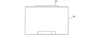
- FIG. 2 is a front view of the rotary damper according to the first embodiment of the present invention.
- FIG. 3 is a cross-sectional view taken along the line AA in FIG. 4 is a cross-sectional view taken along the line BB in FIG.
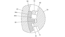
- FIG. 5 is a view for explaining the structure and operation of the check valve employed in Embodiment 1 of the present invention.
- FIG. 6 is a view for explaining the structure and operation of the check valve employed in Embodiment 1 of the present invention.
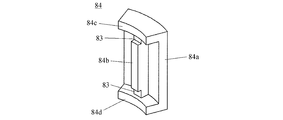
- FIG. 7 is a perspective view of the valve body employed in Example 1 of the present invention.
- FIG. 8 is a cross-sectional view of the rotary damper according to the second embodiment of the present invention.
- FIG. 9 is a cross-sectional view of the rotary damper according to the third embodiment of the present invention.
- FIG. 10 is a perspective view of the valve element employed in Example 3 of the present invention.
- FIG. 11 is a cross-sectional view of a rotary damper according to a fourth embodiment of the present invention.
- FIG. 12 is a cross-sectional view taken along the line CC in FIG.
- FIG. 13 is a view for explaining the structure and operation of a check valve employed in Embodiment 4 of the present invention.
- FIG. 14 is a view for explaining the structure and operation of a check valve employed in Embodiment 4 of the present invention.
- FIG. 15 is a perspective view of a valve element employed in Example 4 of the present invention.
- FIGS. 1 to 4 are views showing a rotary damper according to Embodiment 1 of the present invention.
- the rotary damper according to this embodiment includes a housing 10, a shaft 20, a plug 30, a partition wall 40, a viscous liquid, a vane, and a seal member 60.
- the housing 10 is open at one end and completely closed by the end wall 11 at the other end (see FIG. 3).
- the housing 10 includes a cylindrical peripheral wall 12 formed integrally with the end wall 11, and the interior of the housing 10 is hollow (see FIGS. 3 and 4).
- the end wall 11 has a convex bearing portion 13 (see FIG. 3). Note that the end wall 11 completely closes the other end side of the housing 10, and therefore, a hole that penetrates the end wall 11 cannot be adopted as a bearing portion formed in the end wall 11.
- the shaft 20 has a recess 21 that fits into the bearing portion 13 of the housing 10 (see FIG. 3).
- the plug 30 closes the opening at one end of the housing 10 and is attached to the housing 10 by caulking the end of the peripheral wall 12 of the housing 10 (see FIG. 3).
- a hole 31 for supporting the shaft 20 is formed in the plug 30 (see FIG. 3).
- One end of the shaft 20 is supported by being fitted into the bearing portion 13, and the other end is supported by being inserted through the hole portion 31.
- a partition 40 is provided inside the housing 10 so as to be able to rotate as the housing 10 rotates (see FIG. 4). Viscous liquid is filled in the chambers 71 and 72 partitioned by the partition wall 40 (see FIG. 4).
- a vane is provided so that it can rotate with rotation of the shaft 20 in the inside of the chambers 71 and 72 partitioned off by the partition 40 (refer FIG. 4).
- the vane employed in this embodiment includes a first pressurizing unit 51 and a second pressurizing unit 52.
- the vane (the first pressurizing unit 51 and the second pressurizing unit 52) employed in the present embodiment includes a check valve.
- This check valve includes a valve body 84.
- the check valve includes a first groove 81 formed in the first pressurizing unit 51, a second groove 82 formed in the second pressurizing unit 52, and a third groove formed in the valve body 84.
- the combination with the groove 83 serves to flow the viscous liquid only in one direction.
- first pressurizing unit 51 and the second pressurizing unit 52 are provided at a constant interval, and the first groove 81 is formed at a position away from the shaft 20, and the second groove 82 is formed at a position close to the shaft 20 (see FIGS. 5 and 6).
- the valve body 84 has a width that can always be in contact with the front end surface of the first pressurizing unit 51 and the front end surface of the second pressurizing unit 52.
- a main body portion 84a disposed between the first pressurizing portion 51 and the second pressurizing portion 52.
- the main body portion 84a is disposed between the first pressurizing portion 51 and the second pressurizing portion 52.
- the protrusion 84b is formed with a third groove 83 that can communicate with the second groove 82 when the protrusion 84b contacts the second pressure part 52 (see FIGS. 6 and 7).
- the third groove 83 is formed at a position where the third groove 83 does not communicate with the first groove 81 when the projecting portion 84b contacts the first pressurizing portion 51 (see FIG. 5).
- the second pressurizing unit 52 pressurizes the viscous liquid. Accordingly, the main body portion 84a of the valve body 84 receives the resistance of the viscous liquid, so that the protruding portion 84b of the valve body 84 comes into contact with the first pressurizing portion 51 (see FIG. 5). At this time, the viscous liquid flows into the third groove 83 via the second groove 82, but is blocked by the first pressurizing unit 51 (see FIG. 5). As a result, a braking force that reduces the rotational speed of the shaft 20 is generated.
- the first pressurizing unit 51 pressurizes the viscous liquid, and accordingly, the main body of the valve body 84.
- the protrusion 84b of the valve body 84 comes into contact with the second pressurizing part 52 by the resistance of the viscous liquid 84a (see FIG. 6).
- the viscous liquid flows into the second groove 82 via the first groove 81 and the third groove 83 without being blocked by the second pressurizing unit 52 (see FIG. 6).
- a braking force that reduces the rotational speed of the shaft 20 is not generated.
- the seal member 60 is provided at a position where the viscous liquid can be prevented from flowing into the fitting portion between the bearing portion 13 and the shaft 20. More specifically, it is provided at a position where the viscous liquid can be prevented from flowing between the front end surface 13a of the bearing portion 13 and the one surface 21a of the shaft 20 facing the front end surface 13a.
- the seal member 60 in the present embodiment is provided so as to seal the gap between the outer peripheral surface of the bearing portion 13 and the inner peripheral surface of the concave portion 21 of the shaft 20 (see FIG. 3).
- An O-ring can be used as the seal member 60.
- the rotary damper configured as described above, even when the plug 30 and the vane (the first pressurizing unit 51 and the second pressurizing unit 52) are made of metal, when the housing 10 or the shaft 20 is rotated, The viscous liquid can be prevented from flowing into the fitting portion between the bearing portion 13 and the shaft 20 by the seal member 60 (see FIG. 3). Accordingly, the lift of the shaft 20 is suppressed, and the plug 30 and the vane (the first pressurizing unit 51 and the second pressurizing unit) are formed by the vane (the first pressurizing unit 51 and the second pressurizing unit 52) being in sliding contact with the plug 30. It is possible to reduce the wear of the part 52).
- the experiment was performed using the rotary damper according to the present example and the rotary damper according to the comparative example.
- the rotary damper according to the comparative example is different in configuration from the rotary damper according to this embodiment in that the seal member 60 is not provided.
- the shaft was rotated 30,000 times from the initial position in the direction of generating the braking force with the housing fixed.
- the load applied to the shaft is 14 Nm, and the plugs and vanes of this example and the comparative example are made of metal.
- the thickness of the plug was measured after the experiment, 0.026 mm of wear was confirmed in the comparative example, whereas only 0.012 mm of wear was confirmed in this example.
- the time from when the shaft was rotated 60 degrees in the braking force generation direction from the initial position was measured.
- the time before the experiment was 1.9 seconds and the time after the experiment was 0.8.
- FIG. 8 is a cross-sectional view of the rotary damper according to the second embodiment of the present invention. As shown in this figure, the rotary damper according to the present embodiment is different from the rotary damper according to the first embodiment in that the bearing portion 13 ′ formed on the end wall 11 is concave.
- the seal member 60 in this embodiment is provided so as to seal the gap between the inner peripheral surface of the bearing portion 13 ′ of the housing 10 and the outer peripheral surface of the convex portion 21 ′ of the shaft 20 (see FIG. 8).
- An O-ring can be used as the seal member 60.
- the rotary damper configured as described above, even when the plug 30 and the vane (the first pressurizing unit 51 and the second pressurizing unit 52) are made of metal, when the housing 10 or the shaft 20 is rotated,
- the seal member 60 can prevent the viscous liquid from flowing between the tip surface 21a ′ of the convex portion 21 ′ of the shaft 20 and the one surface 13a ′ of the bearing portion 13 ′ facing the tip surface 21a ′. (See FIG. 8). Therefore, the lift of the shaft 20 is suppressed, and the plug 30 and the vane (the first pressurizing unit 51 and the second pressurizing unit 52) that are generated when the vane (the first pressurizing unit 51 and the second pressurizing unit 52) are brought into sliding contact with the plug 30. It is possible to reduce the wear of the pressure part 52). Therefore, the rotary damper according to the present embodiment also has the same effect as the rotary damper according to the first embodiment.
- FIG. 9 is a cross-sectional view of a rotary damper according to the third embodiment of the present invention
- FIG. 10 is a perspective view of the valve body 84 employed in the present embodiment.
- the rotary damper according to this embodiment is made of a resin in which the valve body 84 is disposed between the plug 30 and the vane (the first pressurizing unit 51 and the second pressurizing unit 52).
- the rotary damper according to the first embodiment is provided with a stopper 84c and a resin stopper 84d disposed between the end wall 11 and the vane (the first pressurizing unit 51 and the second pressurizing unit 52). And different.
- the plug 30 and the plug 30 are separated by the resin stopper 84c. Since it can prevent that a vane (the 1st pressurization part 51 and the 2nd pressurization part 52) contacts directly, abrasion of the plug 30 and the vane (the 1st pressurization part 51 and the 2nd pressurization part 52) is carried out. Can be further reduced.
- the experiment was performed using the rotary damper according to the present example and the rotary damper according to the comparative example.
- the rotary damper according to the comparative example is different from the rotary damper according to the present embodiment in that the seal member 60 is not provided and the valve body 84 does not have the stopper 84c.
- the shaft was rotated 30,000 times from the initial position in the direction of generating the braking force with the housing fixed.
- the load applied to the shaft is 14 Nm, and the plugs and vanes of this example and the comparative example are made of metal.
- the thickness of the plug was measured after the experiment, 0.026 mm of wear was confirmed in the comparative example, whereas only 0.001 mm of wear was confirmed in this example.
- the time from when the shaft was rotated 60 degrees in the braking force generation direction from the initial position was measured.
- the time before the experiment was 1.9 seconds, and the time after the experiment was 0.
- the rotary damper according to the present embodiment even when an eccentric load is applied to the shaft 20 and the shaft 20 rotates while being eccentric, in addition to the stopper 84c, the end wall 11 and the vane (the first additive) Since the resin stopper 84d is interposed between the pressure part 51 and the second pressure part 52), the end wall 11 and the vane (the first pressure part 51 and the second pressure part 52) are also worn. Therefore, the durability can be further increased.
- FIG. 11 and 12 are sectional views of a rotary damper according to the fourth embodiment of the present invention. As shown in these drawings, the rotary damper according to the present embodiment is different from the rotary damper according to the first embodiment in the structure of the vane and the check valve.
- the check valve employed in the present embodiment is a combination of the first groove 86 formed in the vane 50 and the second groove 87 and the third groove 88 formed in the valve body 85, so that the viscous liquid is discharged. It works to flow only in one direction.
- the vane 50 has a first groove 86 at the tip (see FIGS. 13 and 14).
- the valve body 85 has a predetermined width, has a main body portion 85a disposed between the vane 50 and the peripheral wall 12 of the housing 10, and a second groove 87, and protrudes from the main body portion 85a.
- the resin is disposed between the plug 30 and the vane 50, the wall 85b, the third groove 88, the second projecting wall 85c projecting from the main body 85a at a predetermined interval from the first projecting wall 85b, and the plug 30 and the vane 50.
- a resin stopper 85e disposed between the end wall 11 and the vane 50 (see FIGS. 13 to 15).
- the vane 50 is disposed between the first projecting wall 85b and the second projecting wall 85c, and when the vane 50 contacts the second projecting wall 85c, the first groove 86 and the third groove 88 communicate with each other.
- the first groove 86 is closed by the second protruding wall 85c (see FIG. 13).
- the vane 50 comes into contact with the first projecting wall 85b, the first groove 86 and the second groove 87 communicate with each other.
- the check valve configured as described above is configured so that the second protruding wall 85c of the valve body 85 contacts the vane 50 when the shaft 20 rotates clockwise in FIG. 13, that is, when the check valve is closed. (See FIG. 13). At this time, the viscous liquid flows into the third groove 88, but is blocked by the vane 50 (see FIG. 13). As a result, a braking force that reduces the rotational speed of the shaft 20 is generated. On the other hand, when the shaft 20 rotates counterclockwise in FIG. 14, that is, when the check valve is opened, the first projecting wall 85b of the valve body 85 contacts the vane 50 (see FIG. 14). At this time, the viscous liquid flows into the third groove 88 via the second groove 87 and the first groove 86 without being blocked by the vane 50. As a result, a braking force that reduces the rotational speed of the shaft 20 is not generated.
- the plug 30 and the vane 50 can be prevented from coming into direct contact by the resin stopper 85d. Further, wear of the plug 30 and the vane 50 can be further reduced.
Landscapes
- Engineering & Computer Science (AREA)
- General Engineering & Computer Science (AREA)
- Mechanical Engineering (AREA)
- Fluid-Damping Devices (AREA)
Abstract
La présente invention porte sur un amortisseur rotatif comportant : un boîtier creux (10) dont une extrémité est ouverte et dont l'autre extrémité est entièrement obturée par une paroi terminale (11) ; une partie palier (13) formée sur la paroi terminale (11) ; un arbre (20) qui porte sur la partie palier (13) ; des bouchons métalliques (30) qui ont des trous (31) qui supportent l'arbre (20) et qui obturent des ouvertures du boîtier (10) ; des cloisons (40) disposées à l'intérieur du boîtier (10) de manière à pouvoir tourner avec la rotation du boîtier (10) ; un liquide visqueux qui remplit l'intérieur de chambres (71, 72) qui sont séparées par les cloisons (40) ; des palettes métalliques (51, 52) placées dans les chambres (71, 72) de manière à pouvoir tourner avec la rotation de l'arbre (20) ; et un élément d'étanchéité (60) servant à empêcher le liquide visqueux de pénétrer dans une partie de portée entre la partie palier (13) et l'arbre (20).
Priority Applications (1)
| Application Number | Priority Date | Filing Date | Title |
|---|---|---|---|
| JP2013509958A JP5864548B2 (ja) | 2011-04-12 | 2012-04-12 | ロータリーダンパ |
Applications Claiming Priority (2)
| Application Number | Priority Date | Filing Date | Title |
|---|---|---|---|
| JP2011087863 | 2011-04-12 | ||
| JP2011-087863 | 2011-04-12 |
Publications (1)
| Publication Number | Publication Date |
|---|---|
| WO2012141242A1 true WO2012141242A1 (fr) | 2012-10-18 |
Family
ID=47009409
Family Applications (1)
| Application Number | Title | Priority Date | Filing Date |
|---|---|---|---|
| PCT/JP2012/060002 Ceased WO2012141242A1 (fr) | 2011-04-12 | 2012-04-12 | Amortisseur rotatif |
Country Status (2)
| Country | Link |
|---|---|
| JP (1) | JP5864548B2 (fr) |
| WO (1) | WO2012141242A1 (fr) |
Cited By (8)
| Publication number | Priority date | Publication date | Assignee | Title |
|---|---|---|---|---|
| US20140345992A1 (en) * | 2013-05-27 | 2014-11-27 | Bestter (Xiamen) Technology Inc. | Damper |
| JP2015004387A (ja) * | 2013-06-19 | 2015-01-08 | 株式会社ソミック石川 | ロータリダンパーおよび車両用扉の開閉機構 |
| WO2016076234A1 (fr) * | 2014-11-11 | 2016-05-19 | オイレス工業株式会社 | Amortisseur rotatif |
| WO2022264190A1 (fr) | 2021-06-14 | 2022-12-22 | 株式会社ソミックマネージメントホールディングス | Amortisseur rotatif et son procédé de production |
| JPWO2023281554A1 (fr) * | 2021-07-03 | 2023-01-12 | ||
| WO2023148849A1 (fr) | 2022-02-02 | 2023-08-10 | 株式会社ソミックマネージメントホールディングス | Amortisseur rotatif |
| WO2023199810A1 (fr) | 2022-04-13 | 2023-10-19 | 株式会社ソミックマネージメントホールディングス | Amortisseur rotatif et soupape, et procédé de prévention de la réduction du couple d'un amortisseur rotatif causée par l'usure d'une soupape |
| WO2024127871A1 (fr) * | 2022-12-16 | 2024-06-20 | 株式会社ソミックマネージメントホールディングス | Procédé de fabrication d'amortisseur rotatif et amortisseur rotatif |
Families Citing this family (1)
| Publication number | Priority date | Publication date | Assignee | Title |
|---|---|---|---|---|
| JP6173033B2 (ja) * | 2013-05-17 | 2017-08-02 | 不二ラテックス株式会社 | 揺動ダンパー装置 |
Citations (6)
| Publication number | Priority date | Publication date | Assignee | Title |
|---|---|---|---|---|
| JPH0552228A (ja) * | 1991-08-22 | 1993-03-02 | Matsushita Electric Ind Co Ltd | 油圧式回転減速装置 |
| JPH08312694A (ja) * | 1995-05-16 | 1996-11-26 | Tokai Rika Hanbai Kk | 回転減速装置 |
| JP2003206973A (ja) * | 2002-01-16 | 2003-07-25 | Somic Ishikawa Inc | 回転ダンパ |
| JP2004183888A (ja) * | 2002-11-22 | 2004-07-02 | Tok Bearing Co Ltd | 回転ダンパ |
| JP2006242318A (ja) * | 2005-03-04 | 2006-09-14 | Nifco Inc | ダンパー |
| JP2010084866A (ja) * | 2008-09-30 | 2010-04-15 | Nidec Sankyo Corp | ダンパー装置 |
Family Cites Families (2)
| Publication number | Priority date | Publication date | Assignee | Title |
|---|---|---|---|---|
| JPH0526280A (ja) * | 1991-07-25 | 1993-02-02 | Toyoda Mach Works Ltd | 回転式シヨツクアブソーバ |
| ITTO20080083U1 (it) * | 2008-06-13 | 2009-12-13 | Antonino Cultraro | Smorzatore rotativo del tipo a barilotto |
-
2012
- 2012-04-12 JP JP2013509958A patent/JP5864548B2/ja active Active
- 2012-04-12 WO PCT/JP2012/060002 patent/WO2012141242A1/fr not_active Ceased
Patent Citations (6)
| Publication number | Priority date | Publication date | Assignee | Title |
|---|---|---|---|---|
| JPH0552228A (ja) * | 1991-08-22 | 1993-03-02 | Matsushita Electric Ind Co Ltd | 油圧式回転減速装置 |
| JPH08312694A (ja) * | 1995-05-16 | 1996-11-26 | Tokai Rika Hanbai Kk | 回転減速装置 |
| JP2003206973A (ja) * | 2002-01-16 | 2003-07-25 | Somic Ishikawa Inc | 回転ダンパ |
| JP2004183888A (ja) * | 2002-11-22 | 2004-07-02 | Tok Bearing Co Ltd | 回転ダンパ |
| JP2006242318A (ja) * | 2005-03-04 | 2006-09-14 | Nifco Inc | ダンパー |
| JP2010084866A (ja) * | 2008-09-30 | 2010-04-15 | Nidec Sankyo Corp | ダンパー装置 |
Cited By (17)
| Publication number | Priority date | Publication date | Assignee | Title |
|---|---|---|---|---|
| US20140345992A1 (en) * | 2013-05-27 | 2014-11-27 | Bestter (Xiamen) Technology Inc. | Damper |
| US9255621B2 (en) * | 2013-05-27 | 2016-02-09 | Bestter (Xiamen) Technology Inc. | Damper |
| JP2015004387A (ja) * | 2013-06-19 | 2015-01-08 | 株式会社ソミック石川 | ロータリダンパーおよび車両用扉の開閉機構 |
| WO2016076234A1 (fr) * | 2014-11-11 | 2016-05-19 | オイレス工業株式会社 | Amortisseur rotatif |
| JP2016090037A (ja) * | 2014-11-11 | 2016-05-23 | オイレス工業株式会社 | ロータリダンパ |
| US10400846B2 (en) | 2014-11-11 | 2019-09-03 | Oiles Corporation | Rotary damper |
| WO2022264190A1 (fr) | 2021-06-14 | 2022-12-22 | 株式会社ソミックマネージメントホールディングス | Amortisseur rotatif et son procédé de production |
| WO2023281554A1 (fr) | 2021-07-03 | 2023-01-12 | 株式会社ソミックマネージメントホールディングス | Amortisseur rotatif et son procédé de production |
| JPWO2023281554A1 (fr) * | 2021-07-03 | 2023-01-12 | ||
| JP7523182B2 (ja) | 2021-07-03 | 2024-07-26 | 株式会社ソミックマネージメントホールディングス | ロータリーダンパ及びその製造方法 |
| WO2023148849A1 (fr) | 2022-02-02 | 2023-08-10 | 株式会社ソミックマネージメントホールディングス | Amortisseur rotatif |
| WO2023199810A1 (fr) | 2022-04-13 | 2023-10-19 | 株式会社ソミックマネージメントホールディングス | Amortisseur rotatif et soupape, et procédé de prévention de la réduction du couple d'un amortisseur rotatif causée par l'usure d'une soupape |
| JP2023156933A (ja) * | 2022-04-13 | 2023-10-25 | 株式会社ソミックマネージメントホールディングス | ロータリーダンパ及びバルブ並びにバルブの摩耗によるロータリーダンパのトルクの低下を防止する方法 |
| JP7716104B2 (ja) | 2022-04-13 | 2025-07-31 | 株式会社ソミックマネージメントホールディングス | ロータリーダンパ及びバルブ並びにバルブの摩耗によるロータリーダンパのトルクの低下を防止する方法 |
| WO2024127871A1 (fr) * | 2022-12-16 | 2024-06-20 | 株式会社ソミックマネージメントホールディングス | Procédé de fabrication d'amortisseur rotatif et amortisseur rotatif |
| JP2024086051A (ja) * | 2022-12-16 | 2024-06-27 | 株式会社ソミックマネージメントホールディングス | ロータリダンパの製造方法およびロータリダンパ |
| JP7709143B2 (ja) | 2022-12-16 | 2025-07-16 | 株式会社ソミックマネージメントホールディングス | ロータリダンパの製造方法およびロータリダンパ |
Also Published As
| Publication number | Publication date |
|---|---|
| JP5864548B2 (ja) | 2016-02-17 |
| JPWO2012141242A1 (ja) | 2014-07-28 |
Similar Documents
| Publication | Publication Date | Title |
|---|---|---|
| JP5864548B2 (ja) | ロータリーダンパ | |
| US9027979B2 (en) | Rotary damper and opening and closing mechanism for a vehicle door | |
| JP6480155B2 (ja) | ロータリダンパ | |
| US11441632B2 (en) | Rotary damper having simple self-standing mechanism | |
| JPH07301272A (ja) | 流体圧ダンパ | |
| WO2011093130A1 (fr) | Dispositif d'étanchéité, et dispositif de type pompe utilisant celui-ci | |
| JP5681047B2 (ja) | 回転ダンパ | |
| WO2017204022A1 (fr) | Amortisseur rotatif | |
| JP5918222B2 (ja) | ロータリーダンパ | |
| JP5650941B2 (ja) | ドアクローザ | |
| WO2009081894A1 (fr) | Dispositif amortisseur | |
| JP5341260B2 (ja) | 回転ダンパ | |
| JP2005188636A (ja) | ロータリーダンパ | |
| JP2009185522A (ja) | ヒンジ装置 | |
| CA2775667C (fr) | Amortisseur rotatif | |
| JP6325387B2 (ja) | 扉操作補助装置 | |
| WO2023281554A1 (fr) | Amortisseur rotatif et son procédé de production | |
| JP2010048386A (ja) | ロータリーダンパ | |
| JP5546147B2 (ja) | ロータリーダンパ | |
| JP5469772B2 (ja) | ロータリーダンパ | |
| JP2009185901A (ja) | 回転ダンパ | |
| JP2013096565A (ja) | 回転ダンパ | |
| WO2023199810A1 (fr) | Amortisseur rotatif et soupape, et procédé de prévention de la réduction du couple d'un amortisseur rotatif causée par l'usure d'une soupape | |
| JP2024066714A (ja) | ロータリーダンパ | |
| JP5616141B2 (ja) | ロータリーダンパ |
Legal Events
| Date | Code | Title | Description |
|---|---|---|---|
| 121 | Ep: the epo has been informed by wipo that ep was designated in this application |
Ref document number: 12770724 Country of ref document: EP Kind code of ref document: A1 |
|
| ENP | Entry into the national phase |
Ref document number: 2013509958 Country of ref document: JP Kind code of ref document: A |
|
| NENP | Non-entry into the national phase |
Ref country code: DE |
|
| 122 | Ep: pct application non-entry in european phase |
Ref document number: 12770724 Country of ref document: EP Kind code of ref document: A1 |