WO2012144222A1 - Appareil de charge à montage dans un véhicule et véhicule le comportant - Google Patents
Appareil de charge à montage dans un véhicule et véhicule le comportant Download PDFInfo
- Publication number
- WO2012144222A1 WO2012144222A1 PCT/JP2012/002728 JP2012002728W WO2012144222A1 WO 2012144222 A1 WO2012144222 A1 WO 2012144222A1 JP 2012002728 W JP2012002728 W JP 2012002728W WO 2012144222 A1 WO2012144222 A1 WO 2012144222A1
- Authority
- WO
- WIPO (PCT)
- Prior art keywords
- vehicle
- body case
- main body
- charging device
- charging
- Prior art date
- Legal status (The legal status is an assumption and is not a legal conclusion. Google has not performed a legal analysis and makes no representation as to the accuracy of the status listed.)
- Ceased
Links
Images
Classifications
-
- H—ELECTRICITY
- H01—ELECTRIC ELEMENTS
- H01M—PROCESSES OR MEANS, e.g. BATTERIES, FOR THE DIRECT CONVERSION OF CHEMICAL ENERGY INTO ELECTRICAL ENERGY
- H01M10/00—Secondary cells; Manufacture thereof
- H01M10/42—Methods or arrangements for servicing or maintenance of secondary cells or secondary half-cells
- H01M10/46—Accumulators structurally combined with charging apparatus
-
- H—ELECTRICITY
- H02—GENERATION; CONVERSION OR DISTRIBUTION OF ELECTRIC POWER
- H02J—ELECTRIC POWER NETWORKS; CIRCUIT ARRANGEMENTS OR SYSTEMS FOR SUPPLYING OR DISTRIBUTING ELECTRIC POWER; SYSTEMS FOR STORING ELECTRIC ENERGY
- H02J50/00—Circuit arrangements or systems for wireless supply or distribution of electric power
- H02J50/10—Circuit arrangements or systems for wireless supply or distribution of electric power using inductive coupling
-
- H—ELECTRICITY
- H02—GENERATION; CONVERSION OR DISTRIBUTION OF ELECTRIC POWER
- H02J—ELECTRIC POWER NETWORKS; CIRCUIT ARRANGEMENTS OR SYSTEMS FOR SUPPLYING OR DISTRIBUTING ELECTRIC POWER; SYSTEMS FOR STORING ELECTRIC ENERGY
- H02J50/00—Circuit arrangements or systems for wireless supply or distribution of electric power
- H02J50/80—Circuit arrangements or systems for wireless supply or distribution of electric power involving the exchange of data, concerning supply or distribution of electric power, between transmitting devices and receiving devices
-
- H—ELECTRICITY
- H02—GENERATION; CONVERSION OR DISTRIBUTION OF ELECTRIC POWER
- H02J—ELECTRIC POWER NETWORKS; CIRCUIT ARRANGEMENTS OR SYSTEMS FOR SUPPLYING OR DISTRIBUTING ELECTRIC POWER; SYSTEMS FOR STORING ELECTRIC ENERGY
- H02J7/00—Circuit arrangements for charging or discharging batteries or for supplying loads from batteries
- H02J7/70—Circuit arrangements for charging or discharging batteries or for supplying loads from batteries characterised by the mechanical construction
- H02J7/731—Circuit arrangements for charging or discharging batteries or for supplying loads from batteries characterised by the mechanical construction specially adapted for holding portable devices containing batteries
-
- H—ELECTRICITY
- H05—ELECTRIC TECHNIQUES NOT OTHERWISE PROVIDED FOR
- H05K—PRINTED CIRCUITS; CASINGS OR CONSTRUCTIONAL DETAILS OF ELECTRIC APPARATUS; MANUFACTURE OF ASSEMBLAGES OF ELECTRICAL COMPONENTS
- H05K9/00—Screening of apparatus or components against electric or magnetic fields
- H05K9/0007—Casings
-
- H—ELECTRICITY
- H01—ELECTRIC ELEMENTS
- H01M—PROCESSES OR MEANS, e.g. BATTERIES, FOR THE DIRECT CONVERSION OF CHEMICAL ENERGY INTO ELECTRICAL ENERGY
- H01M10/00—Secondary cells; Manufacture thereof
- H01M10/42—Methods or arrangements for servicing or maintenance of secondary cells or secondary half-cells
- H01M10/44—Methods for charging or discharging
-
- H—ELECTRICITY
- H02—GENERATION; CONVERSION OR DISTRIBUTION OF ELECTRIC POWER
- H02J—ELECTRIC POWER NETWORKS; CIRCUIT ARRANGEMENTS OR SYSTEMS FOR SUPPLYING OR DISTRIBUTING ELECTRIC POWER; SYSTEMS FOR STORING ELECTRIC ENERGY
- H02J2105/00—Networks for supplying or distributing electric power characterised by their spatial reach or by the load
- H02J2105/30—Networks for supplying or distributing electric power characterised by their spatial reach or by the load the load networks being external to vehicles, i.e. exchanging power with vehicles
- H02J2105/33—Networks for supplying or distributing electric power characterised by their spatial reach or by the load the load networks being external to vehicles, i.e. exchanging power with vehicles exchanging power with road vehicles
-
- Y—GENERAL TAGGING OF NEW TECHNOLOGICAL DEVELOPMENTS; GENERAL TAGGING OF CROSS-SECTIONAL TECHNOLOGIES SPANNING OVER SEVERAL SECTIONS OF THE IPC; TECHNICAL SUBJECTS COVERED BY FORMER USPC CROSS-REFERENCE ART COLLECTIONS [XRACs] AND DIGESTS
- Y02—TECHNOLOGIES OR APPLICATIONS FOR MITIGATION OR ADAPTATION AGAINST CLIMATE CHANGE
- Y02E—REDUCTION OF GREENHOUSE GAS [GHG] EMISSIONS, RELATED TO ENERGY GENERATION, TRANSMISSION OR DISTRIBUTION
- Y02E60/00—Enabling technologies; Technologies with a potential or indirect contribution to GHG emissions mitigation
- Y02E60/10—Energy storage using batteries
Definitions
- the present invention relates to a vehicle-mounted charging device and a vehicle equipped with the same.
- Patent Document 1 an in-vehicle charging device that can charge the mobile terminal even in a car has been proposed (for example, Patent Document 1 below).
- the in-vehicle charging device includes a case having an opening on one side, a lid that covers the opening of the case so as to be openable and closable, and a charging that is disposed on the inner surface of the case facing the lid.
- the configuration includes a coil.
- the portable terminal when charging a portable terminal using this vehicle-mounted charging device, the portable terminal is accommodated in the case, and the charging coil of the vehicle-mounted charging device is opposed to the charging coil of the portable terminal, so that the power generated by the magnetic flux We are trying to supply.
- the problem with the conventional example is that reliability for vehicle control such as keyless entry control may be lowered.
- the electromagnetic wave emitted from the charging coil affects the wireless communication performed between the remote control key and the vehicle transceiver. give. As a result, the reliability for keyless entry control may be reduced.
- an object of the present invention is to prevent a decrease in reliability with respect to vehicle control such as keyless entry control.
- the present invention includes a main body case that can be attached to a ceiling portion of a vehicle and a charging coil for contactless charging provided in the main body case, and a shield portion that shields electromagnetic waves is provided below the charging coil. This achieves the intended purpose.
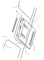
- FIG. 1 shows a state in which a main body case 10 of an in-vehicle charging device 3 is installed on an overhead console in the vicinity of a vehicle ceiling 1 and a windshield 2 in a vehicle.
- Sun visors 4 are attached to the left and right sides of the in-vehicle charging device 3.
- FIG. 1 shows a form in which a plurality of mobile terminals 5 are stored, one mobile terminal 5 may be stored.
- a slit-shaped opening 8a is provided on the vehicle ceiling 1 on the rear side of the main body case 10 installation portion.
- a slit-like opening 8b is provided on the front glass 2 side of the main body case 10.
- main body case 10 has shown the example provided in the overhead console part of the ceiling part of a vehicle, you may provide in the rear-mirror part of a ceiling part.
- FIG. 1 shows a state in which the door 7 is opened when the mobile terminal 5 is stored in the in-vehicle charging device 3, and FIG. 2 shows that the mobile terminal 5 is stored in the in-vehicle charging device 3. It shows the state during charging.
- a coil position adjustment button 9 is provided on the main body case 10 of the in-vehicle charging device 3.
- the coil position adjustment button 9 can adjust the position of the charging coil (14 in FIG. 3) of the in-vehicle charging device 3 in accordance with the charging coil position of the mobile terminal 5.
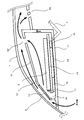
- FIG. 3 shows a cross-sectional view of the main body case 10 of the in-vehicle charging device 3 installed in the overhead console near the vehicle ceiling 1 and the windshield 2 as shown in FIG.
- This sectional view is a view cut at the center of the mobile terminal 5 in a state in which the mobile terminal 5 is stored in the storage unit 6.
- the left is the front of the vehicle, and the right is the rear of the vehicle.
- the front portion of the storage portion 6 of the in-vehicle charging device 3 is configured to face the upper portion of the windshield 2.
- the part of the windshield 2 to which the in-vehicle charging device 3 is attached is made of a material through which electromagnetic waves pass.
- the portable terminal 5 provided with the GPS antenna at the distal end is accommodated in the accommodating part 6, the portable terminal 5 provided with the GPS antenna at the distal end is It becomes possible to receive GPS radio waves satisfactorily.
- the mounting position of the main body case 10 of the in-vehicle charging device 3 may be adjusted in accordance with the mounting position of the GPS antenna of the mobile terminal 5 or a portion through which electromagnetic waves pass may be provided on the vehicle ceiling 1.
- the storage unit 6 is provided with a door 7 for inserting and removing the mobile terminal 5.
- the door 7 has a structure that can be freely opened and closed, and the state shown by the dotted line in FIG. 3 corresponds to FIG.
- the door 7 has a structure that shields electromagnetic waves by attaching a metal plate or the like.
- a shield portion 11 that shields electromagnetic waves is provided on the vehicle interior side (the lower side of the main body case 10) of the main body case 10 constituting the in-vehicle charging device 3. Further, a top surface 12 is provided on the upper side of the main body case 10 (vehicle ceiling 1 side), and the top surface 12 is preferably configured to shield heat.
- a light shielding portion 13 is provided in a portion of the main body case 10 constituting the in-vehicle charging device 3 that faces the windshield 2 of the top surface 12 (a portion that faces a portion through which electromagnetic waves pass).
- the light shielding portion 13 is not visible from the outside through the windshield 2 but allows electromagnetic waves to pass therethrough.
- a circuit board 15 to which a charging coil 14 for contactless charging is attached is installed on the shield portion 11, and an installation table 16 for installing the mobile terminal 5 is provided thereon.
- the installation table 16 has an inclination that lowers the front side (the windshield 2 side) of the vehicle, and a lower side of the inclination is provided with a stopper 17 that regulates the installation position of the mobile terminal 5. 13 is provided at a portion facing 13. With this stopper 17, the mobile terminal 5 having a GPS antenna at the tip is placed in a place where GPS radio waves are received well.
- the charging coil 14 used for contactless charging is provided near the vehicle ceiling 1.
- a shield part 11 for shielding electromagnetic waves is provided below the charging coil 14.
- the shield part 11 shields electromagnetic waves emitted from the charging coil 14 from reaching the predetermined value or more from the lower surface of the main body case 10.
- the shield unit 11 may be made of any material such as a metal plate member as long as it has a characteristic of shielding electromagnetic waves for contactless charging generated between the in-vehicle charging device 3 and the portable terminal 5.
- the shielding range of electromagnetic waves emitted from the charging coil 14 can be adjusted by the shape of the shield part 11 and the door 7.
- the installation table 16 on which the portable terminal 5 is installed is provided with a slope that lowers the front side of the vehicle (the windshield 2 side).
- An opening (first opening) 8c is formed in the wall surface of the main body case 10 below the inclination of the installation table 16, and an opening (second second) is formed on the top surface of the main body case 10 above the inclination of the installation table 16. 8d is provided.
- the opening 8 c is provided at a position lower than the stopper 17 that regulates the installation position of the mobile terminal 5 provided on the installation table 16.
- the cooling air in the vehicle enters from the opening 8 b provided on the front side of the lower surface of the main body case 10, and the opening provided on the top surface 12 through the warmed air passing through the upper portion of the mobile terminal 5. It will come out of 8d.
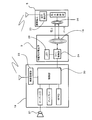
- the in-vehicle charging device 3 is connected to an in-vehicle device 19 installed in the vehicle as shown in FIG.
- the in-vehicle device 19 is an audio device, for example, and the control unit 20 generates sound from the speaker 21.
- a wireless communication unit 22 using Bluetooth (registered trademark) is connected to the control unit 20 and communicates with the terminal communication unit 23 of the mobile terminal 5.
- the in-vehicle charging device 3 connected to the in-vehicle device 19 includes the charging coil 14 and the coil control unit 24, and the charging coil 14 and the charging coil 25 of the mobile terminal 5 are brought close to each other and face each other. , Non-contact charging can be performed.
- contactless charging of the mobile terminal 5 is performed by generating a magnetic flux from the charging coil 14 of the in-vehicle charging device 3 toward the charging coil 25 of the mobile terminal 5. It is also possible to perform data communication at the same time.
- the LED 26 that is exposed on the outer surface of the main body case 10 is connected to the coil control unit 24, and the lighting state of the LED 26 is changed according to the state of the charging coil 14 to notify the charging state of contactless charging.
- the in-vehicle charging device 3 of the present embodiment includes the main body case 10 that can be attached to the ceiling portion of the vehicle, and the charging coil 14 for contactless charging provided in the main body case 10.
- the shield part 11 that shields electromagnetic waves is provided below the charging coil 14.
- This embodiment focuses on the fact that the range of use of remote control keys used for keyless entry control or the like is a place lower than a predetermined height.
- the range for receiving radio waves from the remote control key is often set to be lower than a predetermined height. Therefore, in the present embodiment, as an example, the charging coil 14 used for contactless charging is provided in the vicinity of the ceiling of the vehicle, and the shield portion 11 that shields electromagnetic waves is provided below the charging coil 14.
- the charging coil 14 used for contactless charging is provided in the vicinity of the ceiling of the vehicle, and the shield portion 11 that shields electromagnetic waves is provided below the charging coil 14.
- the present invention has an effect of preventing a decrease in reliability with respect to vehicle control such as keyless entry control.
Landscapes
- Engineering & Computer Science (AREA)
- Power Engineering (AREA)
- Computer Networks & Wireless Communication (AREA)
- Manufacturing & Machinery (AREA)
- Chemical & Material Sciences (AREA)
- Chemical Kinetics & Catalysis (AREA)
- Electrochemistry (AREA)
- General Chemical & Material Sciences (AREA)
- Microelectronics & Electronic Packaging (AREA)
- Charge And Discharge Circuits For Batteries Or The Like (AREA)
- Fittings On The Vehicle Exterior For Carrying Loads, And Devices For Holding Or Mounting Articles (AREA)
Abstract
L'invention porte sur un appareil de charge à montage dans un véhicule, lequel appareil comporte un boîtier de corps (10) qui peut être monté sur une section de plafond d'un véhicule, et un enroulement de charge (14) pour une charge sans contact installé à l'intérieur du boîtier de corps (10). Une diminution de la fiabilité associée à la commande du véhicule, telle qu'une commande d'entrée sans clé, peut être empêchée, par installation d'une section de blindage (11) pour effectuer un blindage vis-à-vis des ondes électromagnétiques sous l'enroulement de charge (14).
Priority Applications (4)
| Application Number | Priority Date | Filing Date | Title |
|---|---|---|---|
| EP12774604.8A EP2701269A4 (fr) | 2011-04-22 | 2012-04-19 | Appareil de charge à montage dans un véhicule et véhicule le comportant |
| JP2013510894A JP6074744B2 (ja) | 2011-04-22 | 2012-04-19 | 車載用充電装置とそれを装着した車両 |
| US13/990,827 US9167732B2 (en) | 2011-04-22 | 2012-04-19 | Vehicle-mounting charging apparatus and vehicle mounted therewith |
| CN201280003953.2A CN103229387B (zh) | 2011-04-22 | 2012-04-19 | 车载充电设备和安装该充电设备的车辆 |
Applications Claiming Priority (2)
| Application Number | Priority Date | Filing Date | Title |
|---|---|---|---|
| JP2011-095772 | 2011-04-22 | ||
| JP2011095772 | 2011-04-22 |
Publications (1)
| Publication Number | Publication Date |
|---|---|
| WO2012144222A1 true WO2012144222A1 (fr) | 2012-10-26 |
Family
ID=47041352
Family Applications (1)
| Application Number | Title | Priority Date | Filing Date |
|---|---|---|---|
| PCT/JP2012/002728 Ceased WO2012144222A1 (fr) | 2011-04-22 | 2012-04-19 | Appareil de charge à montage dans un véhicule et véhicule le comportant |
Country Status (5)
| Country | Link |
|---|---|
| US (1) | US9167732B2 (fr) |
| EP (1) | EP2701269A4 (fr) |
| JP (1) | JP6074744B2 (fr) |
| CN (1) | CN103229387B (fr) |
| WO (1) | WO2012144222A1 (fr) |
Cited By (4)
| Publication number | Priority date | Publication date | Assignee | Title |
|---|---|---|---|---|
| JP2014187782A (ja) * | 2013-03-22 | 2014-10-02 | Honda Motor Co Ltd | 車両用無線充電装置 |
| WO2014177454A3 (fr) * | 2013-05-02 | 2015-01-08 | Bayerische Motoren Werke Aktiengesellschaft | Procédé et dispositif de fonctionnement d'un dispositif de charge sans contact |
| JP2021066200A (ja) * | 2019-10-17 | 2021-04-30 | 本田技研工業株式会社 | 車両用コンソール構造 |
| JP2024139502A (ja) * | 2023-03-27 | 2024-10-09 | ホシデン株式会社 | 車載用非接触給電装置 |
Families Citing this family (15)
| Publication number | Priority date | Publication date | Assignee | Title |
|---|---|---|---|---|
| WO2014017099A1 (fr) * | 2012-07-27 | 2014-01-30 | パナソニック株式会社 | Dispositif chargeur monté dans un véhicule, automobile et système chargeur |
| US10135304B2 (en) | 2013-09-05 | 2018-11-20 | Lg Innotek Co., Ltd. | Supporter |
| CN104779706A (zh) * | 2014-01-10 | 2015-07-15 | 鸿富锦精密工业(深圳)有限公司 | 车用可动部件辅助系统及车辆 |
| CN203896477U (zh) * | 2014-05-20 | 2014-10-22 | 东莞常禾电子有限公司 | 多功能音箱座 |
| CN203945944U (zh) * | 2014-06-06 | 2014-11-19 | 东莞常禾电子有限公司 | 无线充电遮阳板 |
| US9842444B2 (en) * | 2014-06-11 | 2017-12-12 | Ford Global Technologies, Llc | Phone sleeve vehicle fob |
| US9460571B2 (en) | 2014-10-17 | 2016-10-04 | Ford Global Technologies, Llc | Backup key for multiple backup key integration into a mobile device case |
| US9906066B2 (en) * | 2015-04-13 | 2018-02-27 | Motorola Solutions, Inc. | Visor-mountable wireless charger and method of wireless charging |
| DE102015215240A1 (de) * | 2015-08-10 | 2017-02-16 | Volkswagen Aktiengesellschaft | Vorrichtung zum Koppeln eines Mobilkommunikationsgeräts mit einem Kraftfahrzeug |
| US9834105B2 (en) * | 2015-11-16 | 2017-12-05 | Motorola Solutions, Inc. | Apparatus, system and method for in-vehicle wireless charging |
| JP6977663B2 (ja) * | 2018-05-24 | 2021-12-08 | 株式会社オートネットワーク技術研究所 | 車両用ルーフ |
| DE102019109400B4 (de) * | 2019-04-10 | 2026-03-05 | Dr. Ing. H.C. F. Porsche Aktiengesellschaft | Ladevorrichtung für einen elektrischen Ladevorgang eines Mobilgeräts in einem Fahrzeug |
| JP7051761B2 (ja) * | 2019-07-19 | 2022-04-11 | 矢崎総業株式会社 | アンテナモジュール |
| JP7502898B2 (ja) * | 2020-05-25 | 2024-06-19 | 株式会社ヨコオ | 車載装置 |
| US20230294539A1 (en) * | 2022-01-06 | 2023-09-21 | Ev Charging Solutions Llc | Electromagnetic power receiving device for wireless electric vehicle charging |
Citations (3)
| Publication number | Priority date | Publication date | Assignee | Title |
|---|---|---|---|---|
| JP2007104868A (ja) | 2005-10-07 | 2007-04-19 | Toyota Motor Corp | 車両用充電装置、電気機器及び車両用非接触充電システム |
| WO2009031639A1 (fr) * | 2007-09-06 | 2009-03-12 | Showa Denko K.K. | Accumulateur de type à charge sans contact |
| JP2011254634A (ja) * | 2010-06-02 | 2011-12-15 | Tokai Rika Co Ltd | 電子キー充電装置 |
Family Cites Families (12)
| Publication number | Priority date | Publication date | Assignee | Title |
|---|---|---|---|---|
| JPH11208377A (ja) * | 1998-01-22 | 1999-08-03 | Harness Syst Tech Res Ltd | オーバヘッドコンソール |
| DE29817614U1 (de) * | 1998-10-02 | 1998-12-03 | Pyro, Rudolf, 76694 Forst | Haltevorrichtung für ein mobiles Funktelefon |
| US7612528B2 (en) * | 1999-06-21 | 2009-11-03 | Access Business Group International Llc | Vehicle interface |
| DE60028907T2 (de) | 1999-11-24 | 2007-02-15 | Donnelly Corp., Holland | Rückspiegel mit Nutzfunktion |
| EP1494106A1 (fr) * | 2003-07-03 | 2005-01-05 | Hewlett-Packard Development Company, L.P. | Station d'accueil pour un véhicule |
| JP2005112052A (ja) * | 2003-10-03 | 2005-04-28 | Denso Corp | 車室内モジュールおよびインナーミラー |
| DE102005058636A1 (de) | 2005-12-07 | 2007-06-14 | Volkswagen Ag | Kraftfahrzeug |
| DE102006034128A1 (de) | 2006-04-12 | 2007-10-18 | Funkwerk Dabendorf Gmbh | Anordnung zur Aufnahme eines Mobiltelefons innerhalb eines Kraftfahrzeugs |
| DE102006039808B4 (de) * | 2006-08-25 | 2013-05-29 | Johnson Controls Interiors Gmbh & Co. Kg | Vorrichtung für ein Fahrzeug zur induktiven Übertragung von Energie mit Primärspule |
| KR101094253B1 (ko) | 2008-04-28 | 2011-12-19 | 정춘길 | 무선 전력 수신 장치, 이와 관련된 무선 전력 송신 장치, 그리고, 무선 전력 송수신 시스템 |
| US8525471B2 (en) * | 2009-12-28 | 2013-09-03 | Toyoda Gosei Co., Ltd | Moveable magnet and panel assembly useful in a vehicle |
| CN101902062A (zh) | 2010-08-06 | 2010-12-01 | 武汉中原电子集团有限公司 | 一种车载无线充电装置 |
-
2012
- 2012-04-19 WO PCT/JP2012/002728 patent/WO2012144222A1/fr not_active Ceased
- 2012-04-19 CN CN201280003953.2A patent/CN103229387B/zh active Active
- 2012-04-19 US US13/990,827 patent/US9167732B2/en active Active
- 2012-04-19 EP EP12774604.8A patent/EP2701269A4/fr not_active Withdrawn
- 2012-04-19 JP JP2013510894A patent/JP6074744B2/ja not_active Expired - Fee Related
Patent Citations (3)
| Publication number | Priority date | Publication date | Assignee | Title |
|---|---|---|---|---|
| JP2007104868A (ja) | 2005-10-07 | 2007-04-19 | Toyota Motor Corp | 車両用充電装置、電気機器及び車両用非接触充電システム |
| WO2009031639A1 (fr) * | 2007-09-06 | 2009-03-12 | Showa Denko K.K. | Accumulateur de type à charge sans contact |
| JP2011254634A (ja) * | 2010-06-02 | 2011-12-15 | Tokai Rika Co Ltd | 電子キー充電装置 |
Non-Patent Citations (1)
| Title |
|---|
| See also references of EP2701269A4 |
Cited By (7)
| Publication number | Priority date | Publication date | Assignee | Title |
|---|---|---|---|---|
| JP2014187782A (ja) * | 2013-03-22 | 2014-10-02 | Honda Motor Co Ltd | 車両用無線充電装置 |
| WO2014177454A3 (fr) * | 2013-05-02 | 2015-01-08 | Bayerische Motoren Werke Aktiengesellschaft | Procédé et dispositif de fonctionnement d'un dispositif de charge sans contact |
| CN105163977A (zh) * | 2013-05-02 | 2015-12-16 | 宝马股份公司 | 用来运行无接触式充电装置、用来无干扰运行无线闭锁系统的方法和设备 |
| CN105163977B (zh) * | 2013-05-02 | 2017-12-05 | 宝马股份公司 | 用来运行无接触式充电装置、用来无干扰运行无线闭锁系统的方法和设备 |
| US10384554B2 (en) | 2013-05-02 | 2019-08-20 | Bayerische Motoren Werke Aktiengesellschaft | Method and apparatus for operating a contactless charging device for the disturbance free operation of the keyless entry system |
| JP2021066200A (ja) * | 2019-10-17 | 2021-04-30 | 本田技研工業株式会社 | 車両用コンソール構造 |
| JP2024139502A (ja) * | 2023-03-27 | 2024-10-09 | ホシデン株式会社 | 車載用非接触給電装置 |
Also Published As
| Publication number | Publication date |
|---|---|
| EP2701269A4 (fr) | 2015-08-12 |
| CN103229387A (zh) | 2013-07-31 |
| JP6074744B2 (ja) | 2017-02-08 |
| US9167732B2 (en) | 2015-10-20 |
| JPWO2012144222A1 (ja) | 2014-07-28 |
| EP2701269A1 (fr) | 2014-02-26 |
| US20130249482A1 (en) | 2013-09-26 |
| CN103229387B (zh) | 2016-11-16 |
Similar Documents
| Publication | Publication Date | Title |
|---|---|---|
| JP6074744B2 (ja) | 車載用充電装置とそれを装着した車両 | |
| US9979427B2 (en) | Privacy and security systems and methods of use | |
| JP5264974B2 (ja) | 無接点電力伝送装置 | |
| EP1489682B1 (fr) | Véhicule équipé avec un système de télécommunication pour communiquer avec un dispositif de communication portable dans un environnement blindé | |
| US20110014863A1 (en) | Radio opaque container for communication devices upon a vehicle | |
| WO2020121808A1 (fr) | Système de détermination de position | |
| WO2016111727A1 (fr) | Systèmes de confidentialité et de sécurité et procédés d'utilisation | |
| ITMI20140367U1 (it) | Aletta parasole con dispositivo di carica elettrica wireless. | |
| WO2015040841A1 (fr) | Structure d'installation de terminal pour véhicule | |
| WO2017081769A1 (fr) | Dispositif de communication sans fil embarqué dans un véhicule | |
| CN1133310C (zh) | 带有防护使用过程中所产生的辐射的装置的蜂窝电话 | |
| US20140187156A1 (en) | Mobile Wireless Media Head Unit Player | |
| JP2001345620A (ja) | 自動車電話機用アンテナ装置 | |
| CZ308887B6 (cs) | Zařízení pro bezdrátové dobíjení | |
| JP2012186933A (ja) | 車載用電子機器 | |
| US20030162524A1 (en) | Motor vehicle outside rear-view mirror | |
| JPS63254893A (ja) | 肩ベルトマイクロホンマウント | |
| JPH11227536A (ja) | 車両用携帯電話機ホルダー | |
| JPH11155005A (ja) | 携帯電話機車内置き忘れ防止装置 | |
| JP3790316B2 (ja) | 自動車電話システムおよびこれに用いられるアダプタ | |
| JP2001303819A (ja) | 自動車用キーレスエントリー装置 | |
| US20040204187A1 (en) | Support structure for mobile phone with integrated antenna | |
| JP4341151B2 (ja) | 車両内無線通信システム | |
| JP6468178B2 (ja) | 車両窓用シール部材 | |
| JP3245179U (ja) | 車両用ワイヤレス充電器 |
Legal Events
| Date | Code | Title | Description |
|---|---|---|---|
| 121 | Ep: the epo has been informed by wipo that ep was designated in this application |
Ref document number: 12774604 Country of ref document: EP Kind code of ref document: A1 |
|
| ENP | Entry into the national phase |
Ref document number: 2013510894 Country of ref document: JP Kind code of ref document: A |
|
| WWE | Wipo information: entry into national phase |
Ref document number: 13990827 Country of ref document: US |
|
| NENP | Non-entry into the national phase |
Ref country code: DE |