WO2012144240A1 - Fraise - Google Patents
Fraise Download PDFInfo
- Publication number
- WO2012144240A1 WO2012144240A1 PCT/JP2012/050483 JP2012050483W WO2012144240A1 WO 2012144240 A1 WO2012144240 A1 WO 2012144240A1 JP 2012050483 W JP2012050483 W JP 2012050483W WO 2012144240 A1 WO2012144240 A1 WO 2012144240A1
- Authority
- WO
- WIPO (PCT)
- Prior art keywords
- tool
- tip
- cutting
- milling tool
- work material
- Prior art date
- Legal status (The legal status is an assumption and is not a legal conclusion. Google has not performed a legal analysis and makes no representation as to the accuracy of the status listed.)
- Ceased
Links
Images


Classifications
-
- B—PERFORMING OPERATIONS; TRANSPORTING
- B23—MACHINE TOOLS; METAL-WORKING NOT OTHERWISE PROVIDED FOR
- B23C—MILLING
- B23C5/00—Milling-cutters
- B23C5/16—Milling-cutters characterised by physical features other than shape
- B23C5/20—Milling-cutters characterised by physical features other than shape with removable cutter bits or teeth or cutting inserts
-
- B—PERFORMING OPERATIONS; TRANSPORTING
- B23—MACHINE TOOLS; METAL-WORKING NOT OTHERWISE PROVIDED FOR
- B23C—MILLING
- B23C5/00—Milling-cutters
- B23C5/02—Milling-cutters characterised by the shape of the cutter
- B23C5/10—Shank-type cutters, i.e. with an integral shaft
- B23C5/109—Shank-type cutters, i.e. with an integral shaft with removable cutting inserts
-
- B—PERFORMING OPERATIONS; TRANSPORTING
- B23—MACHINE TOOLS; METAL-WORKING NOT OTHERWISE PROVIDED FOR
- B23C—MILLING
- B23C2200/00—Details of milling cutting inserts
- B23C2200/04—Overall shape
- B23C2200/045—Round
-
- B—PERFORMING OPERATIONS; TRANSPORTING
- B23—MACHINE TOOLS; METAL-WORKING NOT OTHERWISE PROVIDED FOR
- B23C—MILLING
- B23C2200/00—Details of milling cutting inserts
- B23C2200/24—Cross section of the cutting edge
- B23C2200/243—Cross section of the cutting edge bevelled or chamfered
-
- B—PERFORMING OPERATIONS; TRANSPORTING
- B23—MACHINE TOOLS; METAL-WORKING NOT OTHERWISE PROVIDED FOR
- B23C—MILLING
- B23C2210/00—Details of milling cutters
- B23C2210/04—Angles
- B23C2210/0407—Cutting angles
- B23C2210/0421—Cutting angles negative
- B23C2210/0428—Cutting angles negative axial rake angle
-
- B—PERFORMING OPERATIONS; TRANSPORTING
- B23—MACHINE TOOLS; METAL-WORKING NOT OTHERWISE PROVIDED FOR
- B23C—MILLING
- B23C2210/00—Details of milling cutters
- B23C2210/04—Angles
- B23C2210/0407—Cutting angles
- B23C2210/0421—Cutting angles negative
- B23C2210/0435—Cutting angles negative radial rake angle
-
- B—PERFORMING OPERATIONS; TRANSPORTING
- B23—MACHINE TOOLS; METAL-WORKING NOT OTHERWISE PROVIDED FOR
- B23C—MILLING
- B23C2210/00—Details of milling cutters
- B23C2210/28—Arrangement of teeth
- B23C2210/285—Cutting edges arranged at different diameters
-
- B—PERFORMING OPERATIONS; TRANSPORTING
- B23—MACHINE TOOLS; METAL-WORKING NOT OTHERWISE PROVIDED FOR
- B23C—MILLING
- B23C2210/00—Details of milling cutters
- B23C2210/28—Arrangement of teeth
- B23C2210/287—Cutting edges arranged at different axial positions or having different lengths in the axial direction
-
- B—PERFORMING OPERATIONS; TRANSPORTING
- B23—MACHINE TOOLS; METAL-WORKING NOT OTHERWISE PROVIDED FOR
- B23C—MILLING
- B23C2250/00—Compensating adverse effects during milling
- B23C2250/16—Damping vibrations
Definitions
- the present invention relates to a milling tool used for cutting, and particularly to a blade-exchangeable milling tool used for cutting difficult-to-cut materials such as super heat-resistant alloys.
- a milling tool having this kind of blade tip replaceable tip is a rotary tool widely used for die processing and material cutting processing, and the tip shape is polygonal and the rake face by the blade tip is circular, A so-called Marukoma chip is known.
- a milling tool using a tip whose tip has a polygonal shape such as a square is used.
- the chip has a polygonal shape
- a three-dimensional digging process or the like becomes a stepped process, resulting in unevenness in machining allowance in the finishing process, and is not suitable for finishing a precise shape. Further, the cutting resistance is large and the tool is likely to be deformed.
- a milling tool using a round piece insert is a plurality of round piece inserts having a circular rake face arranged in the circumferential direction of the rotary tool, and the cutting load is distributed and received by the entire circular cutting edge. Since stress concentration or the like hardly occurs and is not easily broken, there is an advantage that durability is high with respect to cutting of difficult-to-cut materials.
- the cutting edge is circular, the connection between the passes is smooth, the machining allowance for the next process can be made uniform, and the shape of the cutting edge on the track is a curved surface. Cheap.
- the chip thickness at the cutting point smoothly changes from 0 ° (very thin cut) to 90 °, so that the feed can be set high, which is particularly useful for roughing.
- the round piece insert can use the entire circumference of the circle as the cutting edge, so when a part of it is worn, a new cutting point can be set by slightly rotating the insert, which is advantageous in terms of cost. It becomes.
- Patent Document 1 As a conventional technique related to the contact portion at the bottom surface and the side surface portion, for example, in Patent Document 1 described below, in the blade tip replaceable tool having a rectangular tip shape, by changing the protruding amount in the radial direction and the axial direction, A tool is disclosed in which the cutting resistance at the time of cutting is reduced by changing the cutting region of the bottom surface and the side surface to suppress the occurrence of chatter vibration, which causes wear.
- Patent Document 2 below discloses a tool in which a bottom cutting tip and a side cutting tip are separately arranged.
- Patent Document 1 in a chip exchange type milling tool, an offset amount of a mounting position of a square chip is determined, and chattering and regular vibration are prevented by displacing the rotation trajectories.
- it since it is premised on the displacement of the cutting point of the square tip, it cannot be applied to a milling tool using a cylindrical round piece tip having a circular cutting edge.
- the offset angle on the side surface of the tip is not ensured only by offsetting in the axial direction and the radial direction, and cutting of the standing wall surface is not taken into consideration, so abnormal wear on the side surface of the tip is suppressed. The effect for is not obtained.
- the object of the present invention is to enable cutting with high efficiency even when a cylindrical round piece chip made of a ceramic material is used for rough machining with difficult-to-cut materials such as super heat-resistant alloys, and the processing shape. It is an object of the present invention to provide a tool capable of suppressing the abnormal wear of the side surface portion of the blade edge and capable of cutting with a long life even when a standing wall surface is formed due to the above restrictions.
- the milling tool of the present invention is a milling tool in which a plurality of cylindrical round piece chips are arranged at equal intervals in the circumferential direction, and the round piece tip is centered on the tool rotation axis of the milling tool.
- the contact range of the work piece in the set of round piece chips for cutting the bottom surface of the work material and the work piece in the set of round piece chips for cutting the standing wall surface of the work material was set by the distance in the radial direction of the tool from the axis center of the tool rotation axis and the distance in the tool rotation axis direction.
- the radial distance of the tool and the distance in the tool rotation axis direction were displaced from the axis center of the tool rotation axis of the chip by selecting the thickness of the circular piece chip.
- a set of round piece chips to be attached to the above-mentioned milling tool was composed of a combination of round piece chips having different thicknesses.
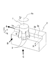
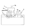
- FIG. 1 is a perspective view of a cutting state by a milling tool having a cylindrical tip.
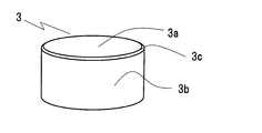
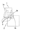
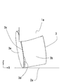
- FIG. 2A is a perspective view of the shape of a chip.
- FIG. 2B is a top view of the shape of the chip.
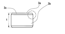
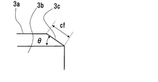
- FIG. 2C is a shape side view of the chip. 2D is an enlarged view of a dotted line portion in FIG. 2C.
- 3A is a front view in the direction of arrow B in FIG. 3B is a bottom view in the direction of arrow C in FIG. 3C is a side view in the direction of arrow A in FIG.
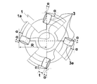
- FIG. 4A is a front view of a milling tool having cylindrical tips evenly arranged.
- FIG. 4B is a bottom view of a milling tool having cylindrical tips evenly arranged.
- FIG. 4A is a front view of a milling tool having cylindrical tips evenly arranged.
- FIG. 4B is a bottom view of a milling tool having cylindrical tips evenly arranged.
- FIG. 4A is
- FIG. 5 is a diagram showing a contact state between a tip and a YZ plane of a work material in a milling tool having a cylindrical tip.
- FIG. 6 is a diagram showing an axial mounting angle of a cylindrical chip.
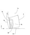
- FIG. 7 is a view showing a noticeable wear state generated in a wide range of the cylindrical tip by the arrangement shown in FIGS. 4A and 4B.
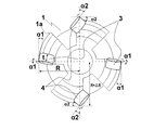
- FIG. 8A is a front view of a milling tool having a cylindrical tip according to the present invention.
- FIG. 8B is a bottom view of a milling tool having a cylindrical tip according to the present invention.
- FIG. 9 is a view showing a contact state between a tip and a YZ plane of a work material in a milling tool having a cylindrical tip according to the present invention.
- FIG. 10 is a view showing a contact state between the tip and the XZ plane of the work material in the milling tool having the cylindrical tip according to the present invention.
- FIG. 11 is a diagram showing a worn state generated on the bottom side of the cylindrical tip according to the present invention.
- FIG. 12 is a view showing a worn state generated on the side surface of the cylindrical tip according to the present invention.
- FIG. 13 is an enlarged view of FIG.
- FIG. 14 is a bottom view of a milling tool having a cylindrical tip according to another embodiment of the present invention.
- FIG. 1 is a perspective view of a state in which an L-shaped work material having a standing wall surface is being cut using a milling tool having a round piece chip.
- 1 is a milling tool for cutting
- 2 is a work material.
- the milling tool 1 includes a tool main body 1a and a round piece chip 3 attached to the tip of the tool main body 1a.
- FIG. 2 shows a detailed shape of the chip 3
- FIG. 2A shows a perspective view
- FIG. 2B shows a top view
- FIG. 2C shows a side view
- FIG. 2D is an enlarged view of a dotted line portion in FIG. 2C.
- the tip 3 is a circular piece tip having a cylindrical shape with a diameter D and a thickness t, and as shown in FIG. 2A, a chamfered portion is formed on the rake face 3a, the flank face 3b, and the boundary between the rake face 3a and the flank face 3b. 3c.
- the chamfered portion 3c is an inclined surface having a chamfering width cf and a chamfering angle ⁇ with respect to the rake surface 3a.
- the chamfering angle ⁇ of the chip 3 is about ⁇ ⁇ 30 °
- the chamfering width cf is cf ⁇ 0.2 mm.
- the tip 3 is fixed to the tool main body 1a with a stopper, a screw or the like not shown.
- the milling tool 1 rotates about a tool rotation axis 1 b in a rotation direction 1 c, and the work material 2 is moved by moving the milling tool 1 in the direction of arrow A in the rotation state.
- the bottom surface 2b and the standing wall surface 2a are cut.
- the chips 3 are arranged at four positions in the circumferential direction with respect to the tool body 1 a and are attached so that the rake face 3 a is in the front direction with respect to the rotation direction of the milling tool 1.
- a standing wall surface 2 a and a bottom surface 2 b having a height H are formed on the work material 2.
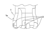
- FIG. 3A to 3C show the cutting state of FIG. 1 in the direction of arrow B, arrow C, and arrow A, respectively.
- FIG. 3A is a front view in the B direction
- FIG. 3B is a bottom view in the direction of the arrow C
- 3C is a side view in the direction of arrow A
- the milling tool 1 moves straight in the direction of arrow A while maintaining the counterclockwise rotational motion 1c shown in FIG. Remove.
- the work material 2 is displaced by a distance d in the Z-axis direction with respect to the work material 2 so as to cut the work material 2 by a depth d in the Z direction. Remove.
- the vertical wall surface 2a and the bottom surface 2b having a height H are cut.
- 1d indicates a curved locus drawn by the tip of the chip 3. The tip 3 moves along a curved locus (1d) on the bottom surface 2a of the workpiece 2 along with the rotational motion 1c of the milling tool 1 and the linear movement in the direction of arrow A, and exists on the locus of the curved locus 1d.
- the work material 2 to be cut is cut.
- the curved locus 1d is a curved line drawn on the bottom surface 2b of the work material 2 at a pitch of the feed amount fz determined by the moving speed in the arrow A direction and the rotational speed of the rotation 1c.
- FIGS. 4A and 4B show a milling tool in which circular chip tips are arranged at equal heights in the Z direction, radial positions with respect to the rotation axis, and mounting angles.
- FIG. 4A is a front view and FIG. 4B is a bottom view.
- the milling tool 1 is mounted such that the tip 3 is constant in the Z direction in the axial direction of the tool body 1.
- tip 3 is arrange
- when the inclination in the tool radial direction on the rake face 3a is defined as a radial mounting angle ⁇ , ⁇ in all the chips 3 is also set to be the same.
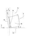
- FIG. 6 is an enlarged view of the dotted line portion shown in FIG. 3A viewed from the Y direction (see FIG. 1).
- the axial mounting angle ⁇ is the same for all the tips 3. That is, the radial mounting angle ⁇ (see FIG. 4B) and the axial mounting angle ⁇ are the same for all the chips 3. This is because, in the milling tool 1 shown in FIG. 4, the radial mounting angle ⁇ and the axial mounting angle ⁇ are designed on the assumption that the bottom surface 2b of the work material 2 is cut, and the standing wall 2a is removed. This is because it is not considered.
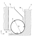
- FIG. 5 shows the Z ⁇ at the cutting edge contact portion of the workpiece 2 and the tip 3 indicated by the dotted line in FIG. 3C when the cutting shown in FIGS. 1 and 3 is performed using the milling tool 1 shown in FIG. It is an enlarged view of the Y plane.
- the tip 3 cuts the standing wall 2 a of the work material 2
- the portion of the outer peripheral surface of the tip 3 in the range indicated by the arc EF comes into contact with the work material 2.
- the circumference of the arc EF is equal to or more than a quarter of the circumference, and the chip 3 is cut in a state where a wide area is in contact with the outer periphery of the chip 3 at the same time.
- a remarkable wear region 3d is generated on the side surface 3b.
- the amount of wear at the contact portion E that is the side surface of the tip 3 is increased.
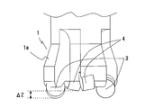
- FIG. 8 shows a front view and a bottom view of the milling tool 1 according to the present invention.
- FIG. 8A is a front view
- FIG. 8B is a bottom view.
- the milling tool 1 of the present embodiment is a tip 3 and a tip 4 that are different from each other in the diametrical position and the axial height position from the central axis 1b of the tool body 1a. They are arranged in pairs in the diameter direction.
- the chip 3 is disposed such that the radial mounting angle of the chip 3 is ⁇ 1 and the radial mounting angle of the chip 4 is ⁇ 2. Further, in the axial mounting angle, the chip 3 is disposed such that the axial mounting angle of the chip 3 is ⁇ 1 and the chip 4 is axially mounted.
- the tip 3 cuts the bottom surface portion 2 b with respect to the work material 2.
- the tip 4 cuts the standing wall surface 2a.
- R the radius of the locus of the circular arc drawn by the tip of the cutting edge of the milling tool 1
- the following three relational expressions must be geometrically satisfied. is necessary. ⁇ 1> 0 ° cos ⁇ 1> D / (2R) 0 ° ⁇ 1 ⁇ 90 °
- FIGS. 1 A method for setting appropriate values of ⁇ 1 and ⁇ 1 will be described with reference to FIGS. That is, the cutting experiment as shown in FIG. 1 is performed by changing the radial mounting angle ⁇ and the axial mounting angle ⁇ .
- the tip 3 is attached on the premise that the bottom surface portion 2b of the work material 2 is cut, a distance is set so that the tip 3 and the standing wall surface 2a of the work material 2 do not come into contact during the experiment, Only the bottom surface portion 2b is cut.
- the wear region 3 d is generated on the side surface 3 b of the chip 3.
- the work material 2 is cut, and the values ⁇ and ⁇ that reduce the width of the wear region 3d are set to the radial mounting angle ⁇ 1 and the axial mounting angle ⁇ 1 of the tip 3, respectively.
- the setting range 6 ° ⁇ 1 ⁇ 30 ° and 0 ° ⁇ 1 ⁇ 20 ° are appropriate.
- the tip 4 is positioned at a distance of ⁇ R from the center of the tool rotation shaft 1 a in the radial direction of the tool with respect to the tip 3. Will be cut.
- the thickness of the tip 4 is t and the radius of the arc locus drawn by the tip of the milling tool 1 is R, the standing wall surface 2a of the work material 2 and the flank 4b of the tip 4 do not interfere with each other. Needs to satisfy the following three relational expressions geometrically. sin ⁇ 2> t / 2 (R + ⁇ R) cos ⁇ 2> D / 2 (R + ⁇ R) 0 ° ⁇ 2 ⁇ 90 °
- a method of setting appropriate values of ⁇ 2 and ⁇ 2 will be described with reference to FIG. That is, the cutting experiment as shown in FIG. 1 is performed by changing the radial mounting angle ⁇ and the axial mounting angle ⁇ .
- the tip 3 is attached on the premise that the bottom surface portion 2b of the work material 2 is cut, a distance is set so that the tip 3 and the standing wall surface 2a of the work material 2 do not come into contact during the experiment, Only the bottom surface portion 2b is cut.
- the wear region 4d is generated on the side surface 4b of the chip 4.
- FIG. 9 shows the Z-- at the cutting edge contact portion of the workpiece 2 and the tips 3 and 4 indicated by the dotted line in FIG. 3C when the cutting shown in FIGS. 1 and 2 is performed using the milling tool 1 of the present embodiment. It is an enlarged view of the Y plane.
- the tip 4 is separated from the tip 3 by a distance ⁇ R in the radial direction of the tool from the center of the tool rotation axis 1a, and a distance away from the bottom surface 2a of the work material 2 by ⁇ Z in the tool rotation axis direction. It is arranged in.
- both the tip 3 and the tip 4 have a cylindrical shape with the same diameter D and thickness t, and the mounting angles, ⁇ R, ⁇ Z of each tip are 3 on the tip mounting surface of the milling tool 1 body.
- the dimensional position it is set to a desired value.
- the cutting edge of the tip 3 is preferentially in the range of E′-F ′ for the bottom surface 2b of the work material 2, and the cutting edge of the tip 4 is preferentially in the range of GE ′ for the standing wall 2a.
- contact with the standing wall 2a does not occur in the chip 3, and contact with the bottom surface 2b does not occur with respect to the chip 4, and each contact range can be greatly reduced, and generation of wear is suppressed.
- the chip 3 can be individually assigned as the bottom surface cutting and the chip 4 as the standing wall surface cutting chip.
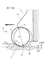
- FIG. 10 is a cross-sectional view of ZX at the cutting edge contact portion of the workpiece 2 and the chips 3 and 4 shown by the dotted line in FIG. 3A when the milling tool 1 of the present invention is used for cutting shown in FIGS. It is an enlarged view of a plane.
- the tip 4 is arranged in the tool body 1 so as to be a distance away from the tip 3 by ⁇ Z in the tool rotation axis direction.
- the cutting edge of the tip 4 can be contacted and removed preferentially in the range of JI with respect to the bottom surface 2b of the work material 2, and the cutting edge of the tip 3 can be contacted and removed with priority in the range of IK.
- the occurrence of wear can be suppressed by limiting the contact range of each blade edge.
- FIG. 11 For the tip 3 and FIG. 12 for the tip 4, the wear region 3d can be greatly reduced.
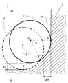
- a method of calculating ⁇ R and ⁇ Z will be described below.
- An enlarged view of FIG. 9 is shown in FIG.
- the center point on the rake face of the chip 3 is P
- the center point on the rake face 4a of the chip 4 is Q.
- the angle ⁇ 1 formed by the contact arc E′F ′ between the tip 3 and the work material 2 with the point P as the center is defined as the cutting angle of the tip 3.
- an angle ⁇ 2 formed by the contact arc E′G between the tip 4 and the work material 2 around the point Q is defined as a cutting angle of the tip 4.
- ⁇ R can be designed from the equation (1) and ⁇ Z from the equation (2).
- ⁇ 1 and ⁇ 2 be at least 2/3 or less of the contact arc EF shown in FIG. 0 ⁇ 1, ⁇ 2 ⁇ 60 ° (3)
- ⁇ R and ⁇ Z are in the following ranges. 0 ⁇ R, ⁇ Z ⁇ 0.18 ⁇ D
- the milling tool 1 according to the present invention is most effective in cutting that causes significant tool wear when machining difficult-to-cut materials such as heat-resistant alloys.
- a ceramic tool was applied as the material of the chip 3 and the chip 4 in consideration of heat resistance during high-efficiency processing.
- Example 2 As another embodiment of the present invention, the thickness t of the tip 4 is changed and attached to the main body of the milling tool 1.
- FIG. 14 shows a bottom view of this embodiment, and is a bottom view showing the milling tool 1 from the same direction as FIG. 8B used in the description of the first embodiment.
- a chip having a chip thickness t2 is disposed on the chip 4, and the radial mounting angle of the chip 3 is ⁇ 1, and the axial mounting angle is ⁇ 1.
- ⁇ 1 and ⁇ 1 are set in the same manner as in the first embodiment.
- the tip 4 is positioned at a distance of ⁇ R from the center of the tool rotating shaft 1a in the radial direction of the tool by cutting the standing wall surface 2a of the work material 2 with respect to the tip 3.
- ⁇ R the thickness of the tip 4
- R the radius of the arc locus drawn by the tip of the milling tool 1
- the standing wall surface 2a of the work material 2 and the flank 4b of the tip 4 do not interfere with each other. Needs to satisfy the following three relational expressions geometrically.
- the radial mounting angle and the radial clearance angle have the same relationship.
- the smaller the clearance angle the higher the cutting edge strength and the higher the wear resistance and chipping properties.
- the clearance angle also increases when the tip thickness is large. Therefore, in this embodiment, the contact range of the tip 4 is limited to the standing wall surface 2a of the work material 2 and the contact on the bottom side is greatly reduced, so that the cutting load of the tip 4 can be reduced.
- the thickness t2 of the tip 4 can be reduced and the clearance angle of the tip 4 can be reduced, so that the cutting edge strength can be increased and the milling tool 1 having high wear resistance can be configured.
- the degree of freedom in setting the radial mounting angle ⁇ 2 is improved, so that the mounting angles of the tip 3 and the tip 4 are suitable for cutting the standing wall surface 2a side and the bottom surface 2b side of the work material 2, respectively. Therefore, it is possible to construct a tool having excellent wear resistance and long life.
- the radial mounting angle ⁇ must be set to 9.2 ° or more.
- ⁇ R in FIG. 9 is set to 0.5 mm
- the thickness t2 of the tip 4 is set to 5 mm, so that the radial mounting angle of the tip 4 can be set to 6 °, and the cutting edge strength is excellent.
- a milling tool 1 can be constructed.
- this invention is not limited to the above-mentioned Example, Various modifications are included.
- the ceramic material tool suitable for the cutting of the super heat resistant alloy has been described.
- the material of the tool is not limited, and a cemented carbide material may be used.
- the material of the work material is effective even if it is not a super heat-resistant alloy, and the same effect can be obtained by processing ordinary steel material, stainless steel material or high hardness material.
- four circular circular piece chips are provided at 90 ° intervals in the circumferential direction, divided into two sets facing each other on the diameter, and one set of chips 3 is used for bottom cutting, and the other set.
- six cylindrical round piece chips are provided at intervals of 60 °, they may be assigned to two sets at intervals of 120 °.
- three or more sets of cylindrical round piece chips arranged at the same circumferential angle are set, and at least one of the sets is set.
- Various modifications are possible, such as a set of round piece chips for cutting the bottom surface of the work material or a set of round piece chips for cutting the standing wall surface of the work material.
- cutting can be performed with high efficiency by simply displacing the tip mounting angle, the distance in the tool radial direction from the center of the tool rotation axis, and the distance in the tool rotation axis direction. Furthermore, even when standing wall surfaces are formed, abnormal wear on the side surface of the blade edge is suppressed, enabling long-life cutting, especially for roughing with difficult-to-cut materials such as super heat-resistant alloys. Expected to be widely adopted.
Landscapes
- Engineering & Computer Science (AREA)
- Mechanical Engineering (AREA)
- Milling Processes (AREA)
Abstract
L'invention porte sur une fraise. Le but de la présente invention consiste à permettre d'obtenir une coupe à haut rendement dans le travail de dégrossissage d'un alliage à très haute résistance à la chaleur ou d'une autre matière difficile à usiner, de supprimer l'usure anormale de la surface latérale d'une arête de lame et d'exécuter un travail de coupe de longue durée même lorsqu'il s'agit de former une surface de paroi verticale. L'invention a pour objet une fraise ayant une pluralité de pointes de boutons cylindriques disposées à intervalles réguliers dans une direction circonférentielle, les pointes de boutons étant divisées en groupes de pointes de boutons disposées à angle sur le tour du même cercle centré sur l'axe de rotation de la fraise. Au moins l'un de ces groupes est divisé en un groupe de pointes de boutons servant à tailler la surface de plancher d'une matière à usiner et un groupe de pointes de boutons servant à tailler la surface verticale d'une matière à usiner, par un déplacement des angles de montage des pointes, de la distance du centre de l'axe de rotation de l'outil dans la direction radiale de l'outil et de la distance dans la direction de l'axe de rotation, par rapport aux autres groupes.
Applications Claiming Priority (2)
| Application Number | Priority Date | Filing Date | Title |
|---|---|---|---|
| JP2011-075870 | 2011-03-30 | ||
| JP2011075870A JP5580239B2 (ja) | 2011-03-30 | 2011-03-30 | フライス工具 |
Publications (1)
| Publication Number | Publication Date |
|---|---|
| WO2012144240A1 true WO2012144240A1 (fr) | 2012-10-26 |
Family
ID=47041367
Family Applications (1)
| Application Number | Title | Priority Date | Filing Date |
|---|---|---|---|
| PCT/JP2012/050483 Ceased WO2012144240A1 (fr) | 2011-03-30 | 2012-01-12 | Fraise |
Country Status (2)
| Country | Link |
|---|---|
| JP (1) | JP5580239B2 (fr) |
| WO (1) | WO2012144240A1 (fr) |
Cited By (1)
| Publication number | Priority date | Publication date | Assignee | Title |
|---|---|---|---|---|
| KR20170021254A (ko) * | 2014-06-18 | 2017-02-27 | 고쿠리츠 다이가쿠 호우징 나고야 다이가쿠 | 날끝 회전식 밀링 공구 및 이것을 사용한 절삭 방법 |
Families Citing this family (6)
| Publication number | Priority date | Publication date | Assignee | Title |
|---|---|---|---|---|
| US20150104262A1 (en) * | 2013-04-01 | 2015-04-16 | EIP Holdings, LLC | Round tooth cutters and method of design and use |
| JP2018202551A (ja) * | 2017-06-05 | 2018-12-27 | 国立大学法人名古屋大学 | 切削工具、切削装置、及び切削方法 |
| JP7004088B2 (ja) * | 2018-11-29 | 2022-02-04 | 日立金属株式会社 | 付加製造体の製造方法、および、付加製造体の製造装置 |
| WO2020137571A1 (fr) * | 2018-12-26 | 2020-07-02 | 日東工器株式会社 | Élément de maintien de pointe, machine de chanfreinage et pointe de coupe |
| JP7250720B2 (ja) * | 2019-06-20 | 2023-04-03 | Jfeスチール株式会社 | 切削工具および切削方法 |
| EP3791985A1 (fr) * | 2019-09-10 | 2021-03-17 | Flender GmbH | Outil de taillage à la molette et procédé de production par enlèvement de copeaux d'une denture d'une roue dentée par taillage à la molette |
Citations (4)
| Publication number | Priority date | Publication date | Assignee | Title |
|---|---|---|---|---|
| JPS5783308A (en) * | 1980-11-04 | 1982-05-25 | Daijietsuto Kogyo Kk | Circular throw-away tip |
| JP2001232513A (ja) * | 2000-02-18 | 2001-08-28 | Mitsubishi Materials Corp | スローアウェイ式カッターおよびスローアウェイチップ |
| JP2004223630A (ja) * | 2003-01-21 | 2004-08-12 | Toshiba Tungaloy Co Ltd | 正面フライス |
| JP2009066677A (ja) * | 2007-09-11 | 2009-04-02 | Sumitomo Electric Hardmetal Corp | スローアウェイチップ |
-
2011
- 2011-03-30 JP JP2011075870A patent/JP5580239B2/ja not_active Expired - Fee Related
-
2012
- 2012-01-12 WO PCT/JP2012/050483 patent/WO2012144240A1/fr not_active Ceased
Patent Citations (4)
| Publication number | Priority date | Publication date | Assignee | Title |
|---|---|---|---|---|
| JPS5783308A (en) * | 1980-11-04 | 1982-05-25 | Daijietsuto Kogyo Kk | Circular throw-away tip |
| JP2001232513A (ja) * | 2000-02-18 | 2001-08-28 | Mitsubishi Materials Corp | スローアウェイ式カッターおよびスローアウェイチップ |
| JP2004223630A (ja) * | 2003-01-21 | 2004-08-12 | Toshiba Tungaloy Co Ltd | 正面フライス |
| JP2009066677A (ja) * | 2007-09-11 | 2009-04-02 | Sumitomo Electric Hardmetal Corp | スローアウェイチップ |
Cited By (4)
| Publication number | Priority date | Publication date | Assignee | Title |
|---|---|---|---|---|
| KR20170021254A (ko) * | 2014-06-18 | 2017-02-27 | 고쿠리츠 다이가쿠 호우징 나고야 다이가쿠 | 날끝 회전식 밀링 공구 및 이것을 사용한 절삭 방법 |
| US20170113287A1 (en) * | 2014-06-18 | 2017-04-27 | National University Corporation Nagoya University | Rotating-cutting-edge-type milling tool and cutting method using same |
| US10300539B2 (en) * | 2014-06-18 | 2019-05-28 | National University Corporation Nagoya University | Rotating-cutting-edge-type milling tool and cutting method using same |
| KR102251915B1 (ko) | 2014-06-18 | 2021-05-13 | 고쿠리츠 다이가쿠 호우징 도우카이 고쿠리츠 다이가쿠 기코우 | 날끝 회전식 밀링 공구 및 이것을 사용한 절삭 방법 |
Also Published As
| Publication number | Publication date |
|---|---|
| JP2012206243A (ja) | 2012-10-25 |
| JP5580239B2 (ja) | 2014-08-27 |
Similar Documents
| Publication | Publication Date | Title |
|---|---|---|
| JP6532940B2 (ja) | 両面型切削インサートおよびフライス工具 | |
| JP5580239B2 (ja) | フライス工具 | |
| KR101720553B1 (ko) | 절삭 인서트, 절삭 공구 및 절삭 가공물의 제조 방법 | |
| JP5679042B2 (ja) | ガイドパッド、切削工具本体および切削工具 | |
| US9278396B2 (en) | Double-sided cutting insert for milling | |
| JP6347258B2 (ja) | ラジアスエンドミル及び切削加工方法 | |
| JP5088678B2 (ja) | ロングネックラジアスエンドミル | |
| KR20120123463A (ko) | 커팅 인서트 및 절삭 공구 | |
| CN104209566A (zh) | 具有高斜面角能力的端铣刀 | |
| WO2005102572A1 (fr) | Fraise en bout a boulets | |
| JP5556957B2 (ja) | 切削インサートおよび切削工具 | |
| WO2018061227A1 (fr) | Plaquette de coupe et outil de coupe | |
| JP5652540B2 (ja) | ガイドパッド、切削工具本体および切削工具 | |
| JP5644084B2 (ja) | 超硬合金製エンドミル | |
| JP6788032B2 (ja) | 回転工具 | |
| JP2011194565A (ja) | フライスカッター及び転削インサート | |
| WO2014156490A1 (fr) | Fraise en bout de degrossissage | |
| JPH0526605B2 (fr) | ||
| JP6292425B2 (ja) | 刃先交換式回転切削工具 | |
| JP5953173B2 (ja) | 切削工具 | |
| JP7706561B2 (ja) | 回転工具、及び切削加工物の製造方法 | |
| KR102342235B1 (ko) | 측면 플랫 가공과 그 인접한 모서리의 라운드 가공이 동시에 가능한 엔드밀 | |
| JP3172438U (ja) | フライス工具 | |
| JP2023050214A (ja) | エンドミル | |
| JP2004017275A (ja) | あさり刃仕様超硬ソリッドメタルソー |
Legal Events
| Date | Code | Title | Description |
|---|---|---|---|
| 121 | Ep: the epo has been informed by wipo that ep was designated in this application |
Ref document number: 12774174 Country of ref document: EP Kind code of ref document: A1 |
|
| NENP | Non-entry into the national phase |
Ref country code: DE |
|
| 122 | Ep: pct application non-entry in european phase |
Ref document number: 12774174 Country of ref document: EP Kind code of ref document: A1 |