WO2012144270A1 - Mounting structure for sonar sensor - Google Patents
Mounting structure for sonar sensor Download PDFInfo
- Publication number
- WO2012144270A1 WO2012144270A1 PCT/JP2012/054599 JP2012054599W WO2012144270A1 WO 2012144270 A1 WO2012144270 A1 WO 2012144270A1 JP 2012054599 W JP2012054599 W JP 2012054599W WO 2012144270 A1 WO2012144270 A1 WO 2012144270A1
- Authority
- WO
- WIPO (PCT)
- Prior art keywords
- sonar sensor
- holder
- mounting structure
- bumper
- resin member
- Prior art date
- Legal status (The legal status is an assumption and is not a legal conclusion. Google has not performed a legal analysis and makes no representation as to the accuracy of the status listed.)
- Ceased
Links
Images


Classifications
-
- G—PHYSICS
- G01—MEASURING; TESTING
- G01S—RADIO DIRECTION-FINDING; RADIO NAVIGATION; DETERMINING DISTANCE OR VELOCITY BY USE OF RADIO WAVES; LOCATING OR PRESENCE-DETECTING BY USE OF THE REFLECTION OR RERADIATION OF RADIO WAVES; ANALOGOUS ARRANGEMENTS USING OTHER WAVES
- G01S15/00—Systems using the reflection or reradiation of acoustic waves, e.g. sonar systems
- G01S15/02—Systems using the reflection or reradiation of acoustic waves, e.g. sonar systems using reflection of acoustic waves
-
- B—PERFORMING OPERATIONS; TRANSPORTING
- B60—VEHICLES IN GENERAL
- B60R—VEHICLES, VEHICLE FITTINGS, OR VEHICLE PARTS, NOT OTHERWISE PROVIDED FOR
- B60R19/00—Wheel guards; Radiator guards, e.g. grilles; Obstruction removers; Fittings damping bouncing force in collisions
- B60R19/02—Bumpers, i.e. impact receiving or absorbing members for protecting vehicles or fending off blows from other vehicles or objects
- B60R19/48—Bumpers, i.e. impact receiving or absorbing members for protecting vehicles or fending off blows from other vehicles or objects combined with, or convertible into, other devices or objects, e.g. bumpers combined with road brushes, bumpers convertible into beds
- B60R19/483—Bumpers, i.e. impact receiving or absorbing members for protecting vehicles or fending off blows from other vehicles or objects combined with, or convertible into, other devices or objects, e.g. bumpers combined with road brushes, bumpers convertible into beds with obstacle sensors of electric or electronic type
-
- G—PHYSICS
- G01—MEASURING; TESTING
- G01S—RADIO DIRECTION-FINDING; RADIO NAVIGATION; DETERMINING DISTANCE OR VELOCITY BY USE OF RADIO WAVES; LOCATING OR PRESENCE-DETECTING BY USE OF THE REFLECTION OR RERADIATION OF RADIO WAVES; ANALOGOUS ARRANGEMENTS USING OTHER WAVES
- G01S7/00—Details of systems according to groups G01S13/00, G01S15/00, G01S17/00
- G01S7/52—Details of systems according to groups G01S13/00, G01S15/00, G01S17/00 of systems according to group G01S15/00
- G01S7/521—Constructional features
-
- G—PHYSICS
- G01—MEASURING; TESTING
- G01S—RADIO DIRECTION-FINDING; RADIO NAVIGATION; DETERMINING DISTANCE OR VELOCITY BY USE OF RADIO WAVES; LOCATING OR PRESENCE-DETECTING BY USE OF THE REFLECTION OR RERADIATION OF RADIO WAVES; ANALOGOUS ARRANGEMENTS USING OTHER WAVES
- G01S15/00—Systems using the reflection or reradiation of acoustic waves, e.g. sonar systems
- G01S15/88—Sonar systems specially adapted for specific applications
- G01S15/93—Sonar systems specially adapted for specific applications for anti-collision purposes
- G01S15/931—Sonar systems specially adapted for specific applications for anti-collision purposes of land vehicles
- G01S2015/937—Sonar systems specially adapted for specific applications for anti-collision purposes of land vehicles sensor installation details
- G01S2015/938—Sonar systems specially adapted for specific applications for anti-collision purposes of land vehicles sensor installation details in the bumper area
Definitions
- the present invention relates to a mounting structure of a sonar sensor that detects a distance from a detection object.
- Patent Document 1 discloses a mounting structure in which a sonar sensor that detects a distance from a detection target is assembled to a bumper without impairing the appearance.
- the sonar sensor is opened to the bumper by the holder so that the detection surface [detector ⁇ ⁇ plane] of the sonar sensor and the outer surface of the bumper are a smooth continuous surface [flush surface]. It is attached to the through hole. Since the detection surface and the outer surface of the bumper are a smooth continuous surface (flash surface), the appearance is improved.
- the detection surface and the bumper are painted in the same color in order to further improve the appearance.
- the material of the detection surface is generally formed of a metal such as aluminum, but the bumper is formed of a resin such as PP (polypropylene).
- the detection surface must be painted with a metal paint, and the bumper must be painted with a resin paint.
- painting with a different paint is required, which increases the painting cost.
- An object of the present invention is to provide a sonar sensor mounting structure capable of suppressing the coating cost by using a common paint.
- a feature of the present invention is a mounting structure of a sonar sensor, which includes a sensor body having a detection surface, transmits ultrasonic waves from the detection surface, and receives reflected waves of ultrasonic waves reflected by a detection object.
- the sonar sensor for detecting the distance to the detection object, a resin member to which the sonar sensor is attached, in which a hole is opened, and a holder that has a cover that covers the detection surface and holds the sonar sensor.
- the sonar sensor is mounted on the holder, the cover portion is inserted into the hole portion from the inside of the resin member, and the outer surface of the cover portion is substantially flush with the outer surface of the resin member.
- a sonar sensor mounting structure in which the holder is attached to the resin member, and at least the cover portion of the holder is molded of resin. That.
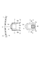
- FIG. 1 is a perspective view of an embodiment of a sonar sensor mounting structure as viewed from the bumper surface side.
- FIG. 2 is a cross-sectional view of the above embodiment.
- FIG. 3 is an exploded cross-sectional view of the above embodiment.
- FIG. 1 shows the sonar sensor attached to the bumper as seen from the bumper surface side.
- FIG. 2 shows a cross section of a sonar sensor attached to a bumper via a holder.
- FIG. 3 shows a cross section of the holder and the sonar sensor before assembly to the bumper. 2 and 3, the side surface of the sonar sensor 2 is shown.
- a holder 5 having a cover portion 4 covering the detection surface 3 a of the sonar sensor 2 is fixed to the bumper 1.
- the bumper 1 is formed with a hole 6 into which the cover 4 that covers the detection surface 3a is inserted.
- the hole 6 is a circular hole penetrating in the bumper thickness direction.
- the outer surface 1b opposite to the inner surface 1a to which the sonar sensor 2 is attached is the outer side of the vehicle body.
- the outer surface 1b is painted.
- the sonar sensor 2 transmits an ultrasonic wave (ultrasound wave) H from the detection surface 3 a of the sensor body [sensor main body] 7 toward the detection object 8 and is reflected by the detection object 8. The reflected wave is received and the distance to the detection object 8 is detected.
- a lock claw [lock pawls] 9 (see FIG. 3) that prevents the sonar sensor 2 attached to the holder 4 from falling off is protruded from the side surface of the sensor body 7.
- the sonar sensor 2 attached by the lock claw 9 is held by the holder 4 so as not to easily fall off in the removal direction B opposite to the insertion direction A in FIG.
- the sensor body 7 is provided with a connector 10 for electrical connection with a controller (not shown).
- the connector 10 is connected to a connector attached to the front end of the body harness on the vehicle body side.
- the connector 10 is provided on one side of a rectangular or polygonal shape of the sensor body 7.
- the holder 5 is formed as a cylindrical case including the above-described cover portion 4 that covers the detection surface 3 a of the sonar sensor 2 and the holder main body 11 that surrounds the sensor main body 7.
- the cover part 4 has a low cylindrical shape covering the entire detection part 3 of the sonar sensor 2.
- the cover part 4 has a thickness that allows the ultrasonic wave H transmitted from the detection surface 3a of the sonar sensor 2 to pass therethrough [has a thickness enabling penetration of the ultrasound wave ...].
- an elastic material [elastic material] or an air layer [air] for acoustic separation is provided between the detection surface 3a as a vibration diaphragm and the cover portion 4. space] is provided.
- an internal space [internal chamber] that can accommodate the sensor body 7 is formed inside the holder body 11.
- the holder body 11 is formed with clip pieces [clipping tabs] 12 that engage with the lock claws 9 described above.
- the clip piece 12 has a hole 12b that engages with the rear end 9a of the lock claw 9 (see FIG. 3).
- a bent end [bent edge] 12a that is bent outward is formed at each edge of the clip piece 12 (see FIG. 3).
- the clip piece 12 can be elastically deformed.
- the sonar sensor 2 is attached to the holder 5, first, the front end inclined surface 9b of the lock claw 9 pushes the bent end 12a outward, and the clip piece 12 is elastically deformed outward.
- the clip piece 12 returns to its original shape by its own elastic restoring force, and the rear end 9a of the lock claw 9 and the hole 12b are engaged. .
- the hole 12b may be formed as a recess.
- the holder 5 has at least the cover 4 formed of the same resin material as that of the bumper 1. Of course, the entire holder 5 including the cover portion 4 may be formed of the same resin material as that of the bumper 1.
- the holder 5 configured in this way is fixed to the inner surface 1a from the inside of the bumper 1.
- various fixing methods using, for example, adhesive, welding, spray-bonding [spray-applied fixation] or screw fastening [screw fastening] can be applied.
- the holder 5 is fixed to the inner surface 1 a of the bumper 1. Specifically, first, the cover 4 of the holder 5 is inserted into the hole 6 from the inside of the bumper 1. At this time, the outer surface 4a of the cover part 4 is substantially flush with the outer surface 1b of the bumper 1 (forms a smooth continuous surface). In this state, the holder 5 is fixed to the inner surface 1a by the fixing method described above.
- the sonar sensor 2 is inserted into the holder 5 so that the detection unit 3 is housed in the cover unit 4.
- the detection unit 3 is covered with the cover unit 4, and the sensor body 7 is surrounded by the holder body 11. Further, the sonar sensor 2 is prevented from falling off the holder 5 by the engagement of the clip piece 12 and the lock claw 9.
- the cover 4 is interposed between the hole 6 and the detection unit 3 of the bumper 1, the gap between the hole 6 and the detection unit 3 is not visible (or almost invisible) from the outside, and the appearance is improved. Will improve.
- the conventional sonar sensor if the sonar sensor is mounted so that the detection unit and the bumper are in direct contact, the ultrasonic wave emitted from the detection surface propagates through the bumper to the detection surface of another adjacent sonar sensor and malfunctions. Cause. In order to prevent this malfunction, in the conventional sonar sensor, it is necessary to provide a gap between the detection unit and the bumper so that they do not directly contact each other.
- the gap is filled with the cover portion 4, the bumper 1 and the detection surface 3 a are not in direct contact with each other, and a gap that can be seen from the outside of the bumper 1 does not occur.
- the outer surface 4a of the cover part 4 and the outer surface 1b of the bumper 1 are painted with the same paint that coats the entire bumper 1.
- the holder 5 is attached to the bumper 1 in advance, and then the outer surface 1a of the bumper 1 and the outer surface 4a of the cover part 4 are coated with the same resin paint (painting process).
- the paint also enters the joint between the outer surface 1a of the bumper 1 and the outer surface 4a of the cover portion 4, the surface becomes more even, and is formed as a smoother continuous surface. Appearance is further improved. Further, it is possible to prevent rainwater from entering the seam from the seam.
- the color change with time of the paint is the same on the outer surface 1a of the bumper 1 and the outer surface 4a of the cover portion 4.
- the holder 5 is attached to the bumper 1 in advance, and then whether or not the outer surface 1a of the bumper 1 and the outer surface 4a of the cover part 4 are coated with the same resin paint (painting process) is observed by the relevant part after coating This makes it easy to distinguish.
- the holder 5 may be attached to the bumper 1 after the bumper 1 and the cover portion 4 are separately painted. Also in this case, the appearance of the appearance over time is improved.
- the bumper 1 of the holder 5 are formed of the same resin material, and the outer surface 4a of the cover part 4 and the outer surface 1b of the bumper 1 are painted with the same paint, the bumper 1 With one type of paint used for coating, both can be applied simultaneously in a single painting operation. For this reason, it is not necessary to adjust the color composition as in the case of painting with different types of paints, and the painting work is simplified. Even in the case of multilayer coating, the same painting process is performed on the outer surface 4a of the cover portion 4 and the outer surface 1b of the bumper 1 by the same paint, so that the painting operation is simplified.
- the cover portion 4 covering the detection surface 3a is inserted from the inside of the bumper 1, and the outer surface 1b of the bumper 1 and the outer surface 4a of the cover portion 4 are substantially flush with each other.
- the space between the inner edge and the inner edge is filled with the cover portion 4, and the gap is reduced. Therefore, since the gap visible from the outside of the bumper 1 is reduced, the appearance of the appearance is improved.
- the cover part 4 has a thickness through which the ultrasonic wave H transmitted from the detection surface 3a can pass, the function of the sonar sensor 2 is not hindered, and the sonar sensor 2 exhibits good performance. .
- a structure in which the sonar sensor 2 is inserted and held in the holder 5 is employed.
- the present invention can be applied to a sonar sensor mounting structure in which a sonar sensor is mounted on a bumper (resin member) of a vehicle or the like via a resin holder.
Landscapes
- Engineering & Computer Science (AREA)
- Physics & Mathematics (AREA)
- Radar, Positioning & Navigation (AREA)
- Remote Sensing (AREA)
- Computer Networks & Wireless Communication (AREA)
- General Physics & Mathematics (AREA)
- Mechanical Engineering (AREA)
- Acoustics & Sound (AREA)
- Measurement Of Velocity Or Position Using Acoustic Or Ultrasonic Waves (AREA)
Abstract
Description
本発明は、検知対象物との距離を検出するソナーセンサの取付構造に関する。 The present invention relates to a mounting structure of a sonar sensor that detects a distance from a detection object.
下記特許文献1には、検知対象物との距離を検出するソナーセンサを、外観を損なわずにバンパに組み付ける取付構造が開示されている。この取付構造では、ソナーセンサの検知面[detector plane]とバンパの外表面とが平滑な連続面[continuous smooth surface](フラッシュサーフェス[flush surface])となるように、ソナーセンサがホルダによってバンパに開口された貫通孔に取り付けられる。検知面とバンパの外表面とが平滑な連続面(フラッシュサーフェス)となるので、外観の見栄えが良くなる。また、この取付構造では、更に見栄えを良くするために、検知面とバンパとが同色で塗装される。
The following
しかし、一般的に検知面の材質はアルミニウムなどの金属で形成されるが、バンパはPP(ポリプロピレン)などの樹脂で形成される。このため、各材質に合わせて、検知面を金属用塗料で塗装し、バンパを樹脂用塗料で塗装しなければならない。この結果、異なる塗料での塗装が必要になり、塗装コストが増大していた。 However, the material of the detection surface is generally formed of a metal such as aluminum, but the bumper is formed of a resin such as PP (polypropylene). For this reason, according to each material, the detection surface must be painted with a metal paint, and the bumper must be painted with a resin paint. As a result, painting with a different paint is required, which increases the painting cost.
本発明の目的は、塗料の共通化によって塗装コストを抑制することのできるソナーセンサの取付構造を提供することにある。 An object of the present invention is to provide a sonar sensor mounting structure capable of suppressing the coating cost by using a common paint.
本発明の特徴は、ソナーセンサの取付構造であって、検知面を有するセンサ本体を備え、前記検知面から超音波を送信し、検知対象物によって反射された超音波の反射波を受信することで前記検知対象物との距離を検出する前記ソナーセンサと、孔部が開口された、前記ソナーセンサが取り付けられる樹脂部材と、前記検知面を覆うカバー部を有し、前記ソナーセンサを保持するホルダと、を備えており、前記ソナーセンサが前記ホルダに装着されており、前記カバー部が前記樹脂部材の内側から前記孔部に挿入され、前記カバー部の外表面が前記樹脂部材の外表面とほぼ面一となるように、前記ホルダが前記樹脂部材に取り付けられており、前記ホルダの少なくとも前記カバー部が樹脂で成形されている、ソナーセンサの取付構造を提供する。 A feature of the present invention is a mounting structure of a sonar sensor, which includes a sensor body having a detection surface, transmits ultrasonic waves from the detection surface, and receives reflected waves of ultrasonic waves reflected by a detection object. The sonar sensor for detecting the distance to the detection object, a resin member to which the sonar sensor is attached, in which a hole is opened, and a holder that has a cover that covers the detection surface and holds the sonar sensor. The sonar sensor is mounted on the holder, the cover portion is inserted into the hole portion from the inside of the resin member, and the outer surface of the cover portion is substantially flush with the outer surface of the resin member. Provided is a sonar sensor mounting structure in which the holder is attached to the resin member, and at least the cover portion of the holder is molded of resin. That.
ソナーセンサの取付構造の実施形態を、図面を参照しつつ説明する。本実施形態の取付構造では、ソナーセンサが、ホルダを介して車両のバンパ(樹脂部材[resin member])に取り付けられている。図1は、バンパ表面側から見た、バンパに取り付けられたソナーセンサを示している。図2は、ホルダを介してバンパに取り付けられたソナーセンサの断面を示している。図3は、バンパへの組み付ける前のホルダ及びソナーセンサの断面を示している。なお、図2及び図3の断面図において、ソナーセンサ2は、その側面が示されている。
An embodiment of a sonar sensor mounting structure will be described with reference to the drawings. In the attachment structure of the present embodiment, the sonar sensor is attached to a vehicle bumper (resin member) via a holder. FIG. 1 shows the sonar sensor attached to the bumper as seen from the bumper surface side. FIG. 2 shows a cross section of a sonar sensor attached to a bumper via a holder. FIG. 3 shows a cross section of the holder and the sonar sensor before assembly to the bumper. 2 and 3, the side surface of the
図1に示されるように、ソナーセンサ2の検知面3aを覆うカバー部4を有するホルダ5がバンパ1に固定される。バンパ1には、検知面3aを覆うカバー部4が挿入される孔部6が形成されている。孔部6は、バンパの厚み方向に貫通する円形孔である。バンパ1は、ソナーセンサ2が取り付けられる内表面1aとは反対側の外表面1bが車体外側となる。外表面1bには、塗装が施されている。
As shown in FIG. 1, a
ソナーセンサ2は、図2に示されるように、センサ本体[sensor main body]7の検知面3aから超音波[ultrasound wave]Hを検知対象物8に向けて送信し、検知対象物8によって反射された反射波を受信して、検知対象物8との距離を検出する。センサ本体7の側面からは、ホルダ4に装着されたソナーセンサ2の脱落を防止するロック爪[lock pawls]9(図3参照)が突設されている。ロック爪9によって、装着されたソナーセンサ2は、図2中の挿入方向Aと逆向きの取り外し方向Bに容易に脱落しないようにホルダ4に保持される。また、センサ本体7には、制御装置[controller](図示せず)との電気的接続のためにコネクタ10が設けられている。コネクタ10は、車体側のボディーハーネス先端に取り付けられたコネクタと接続される。コネクタ10は、センサ本体7の矩形又は多角形状の一側面に設けられている。
As shown in FIG. 2, the
ホルダ5は、ソナーセンサ2の検知面3aを覆う上述したカバー部4と、センサ本体7を囲うホルダ本体11とからなる筒状ケースとして成形されている。
The
カバー部4は、ソナーセンサ2の検知部3全体を覆う、高さの低い筒形状を有している。カバー部4は、ソナーセンサ2の検知面3aから送信される超音波Hの通過が可能な厚みを有している[has a thickness enabling penetration of the ultrasound wave...]。なお、ソナーセンサ2が超音波センサである場合、振動ダイアフラムとしての検知面3aとカバー部4との間には、音響的分離[acoustic separation]のための弾性材[elastic material]や空気層[air space]が設けられる。
The
ホルダ本体11の内部には、センサ本体7を収納し得る内部空間[internal chamber]が形成されている。また、ホルダ本体11には、上述したロック爪9と係合するクリップ片[clipping tabs]12が形成されている。クリップ片12には、ロック爪9の後端9aと係合する孔12bが形成されている(図3参照)。また、クリップ片12の各縁には、外方に屈曲する屈曲端[bent edge]12aが形成されている(図3参照)。
Inside the
クリップ片12は、弾性変形可能である。ホルダ5へのソナーセンサ2の取付時には、まず、ロック爪9の前端傾斜面9bが屈曲端12aを外方に押し、クリップ片12が外方に弾性変形する。そして、ソナーセンサ2が図2に示される位置まで挿入されると、クリップ片12はそれ自身の弾性復元力によって元の形状に復帰し、ロック爪9の後端9aと孔12bとが係合する。この結果、ソナーセンサ2の取り外し方向Bへの脱落が防止される。なお、孔12bは、凹部として形成されてもよい。
The
ホルダ5は、少なくともカバー部4が、バンパ1の樹脂材料と同一の樹脂材料で形成されている。もちろん、カバー部4を含めたホルダ5の全体が、バンパ1の樹脂材料と同一の樹脂材料で形成されてもよい。このように構成されたホルダ5は、バンパ1の内側から内表面1aに固定される。ホルダ5の内表面1aへの固定は、例えば、接着剤・溶着・吹き付け結合[spray-applied fixation]又はねじ締結[screw fastening]などを用いた各種の固定方法を適用できる。
The
バンパ1にホルダ5を介してソナーセンサ2を固定するには、まず、ホルダ5をバンパ1の内表面1aに固定する。具体的には、まず、ホルダ5のカバー部4をバンパ1の内側から孔部6に挿入する。この時、カバー部4の外表面4aは、バンパ1の外表面1bとほぼ面一となる(滑らかな連続面を形成する)。この状態で、上述した固定方法でホルダ5が内表面1aに固定される。
In order to fix the
次に、検知部3をカバー部4内に収納するように、ソナーセンサ2がホルダ5の内部に挿入される。ソナーセンサ2がホルダ5の内部に挿入されると、検知部3がカバー部4により覆われ、センサ本体7がホルダ本体11に囲まれる。また、ソナーセンサ2は、クリップ片12とロック爪9との係合によって、ホルダ5からの脱落が防止される。
Next, the
バンパ1の孔部6と検知部3との間にはカバー部4が介在するので、孔部6と検知部3と間の隙間が外側から見えなくなり(又は、ほとんど見えなくなり)、外観の見栄えが向上する。なお、従来のソナーセンサでは、検知部とバンパとが直接接触するようにソナーセンサを装着すると、検知面から発せられた超音波がバンパを伝って隣接する別のソナーセンサの検知面に伝播して、誤動作の原因になる。この誤動作を防止するために、従来のソナーセンサでは、検知部とバンパとが直接接触しないように両者の間に隙間を設ける必要があった。しかし、本実施形態では、隙間がカバー部4によって埋められるので、バンパ1と検知面3aとは直接接触せず、かつ、バンパ1の外側から見えるような隙間も生じない。
Since the
また、カバー部4の外表面4aとバンパ1の外表面1bとは、バンパ1全体を塗装する同じ塗料で塗装される。通常は、バンパ1に予めホルダ5が取り付けられ、その後、バンパ1の外表面1aとカバー部4の外表面4aとが同じ樹脂塗料(塗装工程)で塗装される。このようにすれば、バンパ1の外表面1aとカバー部4との外表面4aとの間の継ぎ目にも塗料が入り込み、表面はより面一となり、一層円滑な連続面として形成されて外観の見栄えがさらに向上する。また、継ぎ目からの雨水などの内部への浸入も防止できる。さらに、同じ樹脂材料に同じ塗料(塗装工程)で塗装が行われるので、塗料の経時的色変化がバンパ1の外表面1aとカバー部4の外表面4aとで同じになる。この結果、経時的な外観の見栄えもさらに向上する。バンパ1に予めホルダ5が取り付けられ、その後、バンパ1の外表面1aとカバー部4の外表面4aとが同じ樹脂塗料(塗装工程)で塗装されたか否かは、塗装後の当該部位を観察することで容易に判別ができる。なお、バンパ1とカバー部4とが別々に塗装された後に、バンパ1にホルダ5が取り付けられてもよい。この場合も、経時的な外観の見栄えは向上する。
Also, the
また、ホルダ5の少なくともカバー部4とバンパ1とが同一の樹脂材料で成形され、かつ、カバー部4の外表面4aとバンパ1の外表面1bとが同じ塗料で塗装されるので、バンパ1の塗装に使用する1種類の塗料で、1回の塗装作業で同時に両者を塗装することができる。このため、別種の塗料で塗装し分ける場合のような色配合調整をする必要が無く、塗装作業が簡略化される。なお、多層塗装の場合も、カバー部4の外表面4aとバンパ1の外表面1bとは同じ塗料によって同じ塗装工程が行われるので、やはり、塗装作業が簡略化される。
Further, since at least the
また、検知面3aを覆うカバー部4がバンパ1の内側から挿入され、バンパ1の外表面1bとカバー部4の外表面4aとがほぼ面一となるので、検知部3と孔部6の内縁との間がカバー部4で埋められ、隙間が減少する。したがって、バンパ1の外側から見える隙間が減少するので、外観の見栄えが向上する。
Further, the
また、カバー部4は、検知面3aから送信される超音波Hが通過可能な厚みを有しているので、ソナーセンサ2の機能に支障をきたすことがなく、ソナーセンサ2は良好な性能を発揮する。
Moreover, since the
上記実施形態では、ソナーセンサ2がホルダ5の内部に挿入されて保持される構造が採用された。しかし、図2に示される中心軸Mの回りにソナーセンサ2がホルダ5の内部で回転する構造が採用されてもよい。ソナーセンサ2をホルダ5内で回転可能であると、ボディーハーネス先端のコネクタがソナーセンサ2の左側に位置する場合でも右側に位置する場合から延びてくる場合でも、ソナーセンサ2のコネクタ10を最適な方向に向けることができる。従って、ボディハーネスの長さを短くすることができる。
In the above embodiment, a structure in which the
日本国特許出願第2011-93813号(2011年4月20日出願)の全ての内容は、ここに参照されることで本明細書に援用される。本発明の実施形態を参照することで上述のように本発明が説明されたが、本発明は上述した実施形態に限定されるものではない。本発明の範囲は、請求の範囲に照らして決定される。 The entire contents of Japanese Patent Application No. 2011-93813 (filed on April 20, 2011) are incorporated herein by reference. Although the present invention has been described above with reference to embodiments of the present invention, the present invention is not limited to the above-described embodiments. The scope of the invention is determined in light of the claims.
本発明は、車両等のバンパ(樹脂部材)に樹脂製のホルダを介してソナーセンサを取り付けるソナーセンサの取付構造に適用できる。 The present invention can be applied to a sonar sensor mounting structure in which a sonar sensor is mounted on a bumper (resin member) of a vehicle or the like via a resin holder.
Claims (5)
検知面を有するセンサ本体を備え、前記検知面から超音波を送信し、検知対象物によって反射された超音波の反射波を受信することで前記検知対象物との距離を検出する前記ソナーセンサと、
孔部が開口された、前記ソナーセンサが取り付けられる樹脂部材と、
前記検知面を覆うカバー部を有し、前記ソナーセンサを保持するホルダと、を備えており、
前記ソナーセンサが前記ホルダに装着されており、
前記カバー部が前記樹脂部材の内側から前記孔部に挿入されて、前記カバー部の外表面が前記樹脂部材の外表面とほぼ面一となるように、前記ホルダが前記樹脂部材に取り付けられており、
前記ホルダの少なくとも前記カバー部が樹脂で成形されている、ソナーセンサの取付構造。 Sonar sensor mounting structure,
The sonar sensor comprising a sensor body having a detection surface, transmitting an ultrasonic wave from the detection surface, and detecting a reflected wave of the ultrasonic wave reflected by the detection target, and detecting a distance from the detection target;
A resin member to which the sonar sensor is attached, in which a hole is opened;
A cover portion that covers the detection surface, and a holder that holds the sonar sensor,
The sonar sensor is mounted on the holder;
The holder is attached to the resin member so that the cover portion is inserted into the hole portion from the inside of the resin member, and the outer surface of the cover portion is substantially flush with the outer surface of the resin member. And
A sonar sensor mounting structure in which at least the cover portion of the holder is formed of resin.
前記カバー部は、前記検知面から送信される超音波の通過が可能な厚みを有している、ソナーセンサの取付構造。 The sonar sensor mounting structure according to claim 1,
The sonar sensor mounting structure, wherein the cover portion has a thickness that allows passage of ultrasonic waves transmitted from the detection surface.
前記ソナーセンサが、前記ホルダ内で回転可能であり、かつ、任意の回転位置で前記ホルダ内に固定される、ソナーセンサの取付構造。 The sonar sensor mounting structure according to claim 1 or 2,
A sonar sensor mounting structure in which the sonar sensor is rotatable in the holder and fixed in the holder at an arbitrary rotational position.
前記カバー部の前記外表面と前記樹脂部材の前記外表面とが、同じ塗料で塗装されている、ソナーセンサの取付構造。 The sonar sensor mounting structure according to any one of claims 1 to 3,
A sonar sensor mounting structure in which the outer surface of the cover part and the outer surface of the resin member are coated with the same paint.
前記ホルダへの前記樹脂部品の取り付け後に、前記カバー部の前記外表面と前記樹脂部材の前記外表面とが、同じ塗料で塗装されている、ソナーセンサの取付構造。 The sonar sensor mounting structure according to claim 4,
A sonar sensor mounting structure in which the outer surface of the cover part and the outer surface of the resin member are coated with the same paint after the resin part is mounted on the holder.
Priority Applications (4)
| Application Number | Priority Date | Filing Date | Title |
|---|---|---|---|
| EP12773645.2A EP2700975B1 (en) | 2011-04-20 | 2012-02-24 | Mounting structure for sonar sensor |
| JP2013510914A JP5965391B2 (en) | 2011-04-20 | 2012-02-24 | Sonar sensor mounting structure |
| CN201280019514.0A CN103492901B (en) | 2011-04-20 | 2012-02-24 | The installation constitution of sonar sensor |
| US14/112,480 US10254401B2 (en) | 2011-04-20 | 2012-02-24 | Mounting structure for sonar sensor |
Applications Claiming Priority (2)
| Application Number | Priority Date | Filing Date | Title |
|---|---|---|---|
| JP2011093813 | 2011-04-20 | ||
| JP2011-093813 | 2011-04-20 |
Publications (1)
| Publication Number | Publication Date |
|---|---|
| WO2012144270A1 true WO2012144270A1 (en) | 2012-10-26 |
Family
ID=47041392
Family Applications (1)
| Application Number | Title | Priority Date | Filing Date |
|---|---|---|---|
| PCT/JP2012/054599 Ceased WO2012144270A1 (en) | 2011-04-20 | 2012-02-24 | Mounting structure for sonar sensor |
Country Status (5)
| Country | Link |
|---|---|
| US (1) | US10254401B2 (en) |
| EP (1) | EP2700975B1 (en) |
| JP (1) | JP5965391B2 (en) |
| CN (1) | CN103492901B (en) |
| WO (1) | WO2012144270A1 (en) |
Cited By (4)
| Publication number | Priority date | Publication date | Assignee | Title |
|---|---|---|---|---|
| WO2014136221A1 (en) * | 2013-03-06 | 2014-09-12 | 三菱電機株式会社 | Obstruction detection device |
| JP6097988B1 (en) * | 2016-06-22 | 2017-03-22 | 本多電子株式会社 | Ultrasonic sensor unit, method for manufacturing the same, and ultrasonic measuring apparatus |
| US11313965B2 (en) | 2017-11-28 | 2022-04-26 | Toyota Jidosha Kabushiki Kaisha | Sensor installation structure |
| JP2022162722A (en) * | 2021-04-13 | 2022-10-25 | 株式会社ニフコ | Sensor mounting structure |
Families Citing this family (13)
| Publication number | Priority date | Publication date | Assignee | Title |
|---|---|---|---|---|
| US10704021B2 (en) | 2012-03-15 | 2020-07-07 | Flodesign Sonics, Inc. | Acoustic perfusion devices |
| WO2015105955A1 (en) | 2014-01-08 | 2015-07-16 | Flodesign Sonics, Inc. | Acoustophoresis device with dual acoustophoretic chamber |
| CN105022065A (en) * | 2014-04-30 | 2015-11-04 | 中兴通讯股份有限公司 | Terminal and range finding method thereof |
| US11377651B2 (en) | 2016-10-19 | 2022-07-05 | Flodesign Sonics, Inc. | Cell therapy processes utilizing acoustophoresis |
| US11708572B2 (en) | 2015-04-29 | 2023-07-25 | Flodesign Sonics, Inc. | Acoustic cell separation techniques and processes |
| EP3118065B2 (en) | 2015-07-13 | 2022-09-28 | SMP Deutschland GmbH | Cladding component for a vehicle and method for securing and aligning a sensor mounting groove on a cladding component |
| US11214789B2 (en) | 2016-05-03 | 2022-01-04 | Flodesign Sonics, Inc. | Concentration and washing of particles with acoustics |
| KR102439221B1 (en) | 2017-12-14 | 2022-09-01 | 프로디자인 소닉스, 인크. | Acoustic transducer actuators and controllers |
| JP7037998B2 (en) * | 2018-04-19 | 2022-03-17 | 本田技研工業株式会社 | Transport equipment |
| JP7024662B2 (en) | 2018-08-24 | 2022-02-24 | 株式会社デンソー | Retainer member |
| JP6830502B2 (en) * | 2019-02-15 | 2021-02-17 | 本田技研工業株式会社 | Sensor mounting structure and energy absorption structure |
| CN111907423B (en) * | 2020-09-09 | 2025-03-25 | 珠海市多泰吉智能技术有限公司 | Sensor device and automobile door |
| US12570230B2 (en) * | 2023-11-03 | 2026-03-10 | Robert Bosch Gmbh | Retainerless sensor mounting arrangement for a metal bumper |
Citations (3)
| Publication number | Priority date | Publication date | Assignee | Title |
|---|---|---|---|---|
| US6318774B1 (en) | 1997-05-09 | 2001-11-20 | Robert Bosch Gmbh | Modular device to be inserted into a vehicle bumper |
| JP2006203563A (en) * | 2005-01-20 | 2006-08-03 | Nippon Soken Inc | Ultrasonic sensor |
| US20070194892A1 (en) * | 2006-02-03 | 2007-08-23 | Gunther Schaaf | Sensor device for vehicles |
Family Cites Families (13)
| Publication number | Priority date | Publication date | Assignee | Title |
|---|---|---|---|---|
| DE19601987A1 (en) * | 1996-01-20 | 1997-07-24 | Teves Gmbh Alfred | Paintable bumper with ultrasonic transducer |
| DE10039060A1 (en) | 2000-08-10 | 2002-03-07 | Rehau Ag & Co | Ultrasonic transducer / sensor for installation in a bumper of a motor vehicle |
| DE10260118A1 (en) * | 2002-12-19 | 2004-07-01 | Valeo Schalter Und Sensoren Gmbh | Ultrasonic sensor and manufacturing process |
| JP2004264264A (en) | 2003-03-04 | 2004-09-24 | Matsushita Electric Works Ltd | Ultrasonic sensor |
| JP4483672B2 (en) * | 2005-04-15 | 2010-06-16 | 株式会社デンソー | Ultrasonic sensor mounting structure |
| JP2006345312A (en) * | 2005-06-09 | 2006-12-21 | Denso Corp | Ultrasonic sensor and ultrasonic transducer |
| JP2007212349A (en) * | 2006-02-10 | 2007-08-23 | Nippon Soken Inc | Obstacle detection device |
| JP4752715B2 (en) * | 2006-10-13 | 2011-08-17 | 株式会社デンソー | Ultrasonic sensor |
| JP2008099102A (en) * | 2006-10-13 | 2008-04-24 | Denso Corp | Ultrasonic sensor |
| JP2008191007A (en) * | 2007-02-05 | 2008-08-21 | Denso Corp | Sensor device mounting structure |
| DE102007043500A1 (en) * | 2007-09-12 | 2009-03-19 | Valeo Schalter Und Sensoren Gmbh | Installation arrangement for a vibration-sensitive component, in particular an ultrasonic transducer, and method for installing the component |
| JP5592079B2 (en) * | 2009-04-28 | 2014-09-17 | 日本セラミック株式会社 | Ultrasonic transceiver |
| JP5406676B2 (en) * | 2009-11-10 | 2014-02-05 | 株式会社ディスコ | Wafer processing equipment |
-
2012
- 2012-02-24 JP JP2013510914A patent/JP5965391B2/en active Active
- 2012-02-24 US US14/112,480 patent/US10254401B2/en active Active
- 2012-02-24 EP EP12773645.2A patent/EP2700975B1/en active Active
- 2012-02-24 WO PCT/JP2012/054599 patent/WO2012144270A1/en not_active Ceased
- 2012-02-24 CN CN201280019514.0A patent/CN103492901B/en active Active
Patent Citations (4)
| Publication number | Priority date | Publication date | Assignee | Title |
|---|---|---|---|---|
| US6318774B1 (en) | 1997-05-09 | 2001-11-20 | Robert Bosch Gmbh | Modular device to be inserted into a vehicle bumper |
| JP2001527480A (en) | 1997-05-09 | 2001-12-25 | ローベルト ボツシユ ゲゼルシヤフト ミツト ベシユレンクテル ハフツング | Device with module for incorporation into a car bumper |
| JP2006203563A (en) * | 2005-01-20 | 2006-08-03 | Nippon Soken Inc | Ultrasonic sensor |
| US20070194892A1 (en) * | 2006-02-03 | 2007-08-23 | Gunther Schaaf | Sensor device for vehicles |
Non-Patent Citations (1)
| Title |
|---|
| See also references of EP2700975A4 |
Cited By (7)
| Publication number | Priority date | Publication date | Assignee | Title |
|---|---|---|---|---|
| WO2014136221A1 (en) * | 2013-03-06 | 2014-09-12 | 三菱電機株式会社 | Obstruction detection device |
| JPWO2014136221A1 (en) * | 2013-03-06 | 2017-02-09 | 三菱電機株式会社 | Obstacle detection device |
| JP6097988B1 (en) * | 2016-06-22 | 2017-03-22 | 本多電子株式会社 | Ultrasonic sensor unit, method for manufacturing the same, and ultrasonic measuring apparatus |
| WO2017221340A1 (en) * | 2016-06-22 | 2017-12-28 | 本多電子株式会社 | Ultrasonic sensor unit, method for manufacturing same, and ultrasonic measuring device |
| US11313965B2 (en) | 2017-11-28 | 2022-04-26 | Toyota Jidosha Kabushiki Kaisha | Sensor installation structure |
| JP2022162722A (en) * | 2021-04-13 | 2022-10-25 | 株式会社ニフコ | Sensor mounting structure |
| JP7551562B2 (en) | 2021-04-13 | 2024-09-17 | 株式会社ニフコ | Sensor mounting structure |
Also Published As
| Publication number | Publication date |
|---|---|
| JP5965391B2 (en) | 2016-08-03 |
| EP2700975B1 (en) | 2023-04-05 |
| EP2700975A4 (en) | 2015-04-15 |
| CN103492901A (en) | 2014-01-01 |
| US20140036632A1 (en) | 2014-02-06 |
| CN103492901B (en) | 2017-11-21 |
| EP2700975A1 (en) | 2014-02-26 |
| US10254401B2 (en) | 2019-04-09 |
| JPWO2012144270A1 (en) | 2014-07-28 |
Similar Documents
| Publication | Publication Date | Title |
|---|---|---|
| JP5965391B2 (en) | Sonar sensor mounting structure | |
| CN107850665B (en) | Ultrasonic sensor device for arrangement on a covering member of a vehicle | |
| CN104641252B (en) | Ultrasonic sensor device and motor vehicle with improved breakaway ring | |
| US9910142B2 (en) | Ultrasonic sensor device comprising a reinforcement holder, arrangement, motor vehicle and corresponding method | |
| CN106257304B (en) | Low reflection radar support | |
| US6941714B2 (en) | Grommet | |
| CN103502840B (en) | Ultrasonic sensor | |
| JP2001527480A (en) | Device with module for incorporation into a car bumper | |
| JP4839587B2 (en) | Ultrasonic sensor mounting structure | |
| CN104246533B (en) | Ultrasonic sensor device for vehicle and method of assembling ultrasonic sensor device for vehicle | |
| JP4869814B2 (en) | Door lining fixing structure and fixing method | |
| CN106061629B (en) | Method for producing an ultrasonic sensor for a motor vehicle | |
| US8910986B1 (en) | Bonded and rotatable vehicle sensor assembly | |
| US20090013782A1 (en) | Sensor Mount, in Particular for Mounting Inter-Vehicle Distance Sensors on Vehicle Components | |
| US11130460B2 (en) | Sensor protector | |
| CN103733250B (en) | Ultrasonic sensor device for vehicles and devices with such an ultrasonic sensor device | |
| JP2001063497A (en) | Mounting structure for ultrasonic sensor | |
| JP2022158504A (en) | vehicle structure | |
| EP3339105B1 (en) | Ultrasonic sensor assembly and mounting assembly | |
| JP4831182B2 (en) | Painting method and painting jig | |
| JP3659153B2 (en) | Ultrasonic transducer | |
| JP6593839B2 (en) | Instrument panel structure | |
| JP2014129014A (en) | Resin spacer for metal bumper and sensor attachment structure | |
| US20250334685A1 (en) | Ultrasonic sensor | |
| WO2014136221A1 (en) | Obstruction detection device |
Legal Events
| Date | Code | Title | Description |
|---|---|---|---|
| 121 | Ep: the epo has been informed by wipo that ep was designated in this application |
Ref document number: 12773645 Country of ref document: EP Kind code of ref document: A1 |
|
| WWE | Wipo information: entry into national phase |
Ref document number: 2012773645 Country of ref document: EP |
|
| ENP | Entry into the national phase |
Ref document number: 2013510914 Country of ref document: JP Kind code of ref document: A |
|
| WWE | Wipo information: entry into national phase |
Ref document number: 14112480 Country of ref document: US |
|
| NENP | Non-entry into the national phase |
Ref country code: DE |