WO2012144270A1 - Structure de montage pour un capteur sonar - Google Patents
Structure de montage pour un capteur sonar Download PDFInfo
- Publication number
- WO2012144270A1 WO2012144270A1 PCT/JP2012/054599 JP2012054599W WO2012144270A1 WO 2012144270 A1 WO2012144270 A1 WO 2012144270A1 JP 2012054599 W JP2012054599 W JP 2012054599W WO 2012144270 A1 WO2012144270 A1 WO 2012144270A1
- Authority
- WO
- WIPO (PCT)
- Prior art keywords
- sonar sensor
- holder
- mounting structure
- bumper
- resin member
- Prior art date
- Legal status (The legal status is an assumption and is not a legal conclusion. Google has not performed a legal analysis and makes no representation as to the accuracy of the status listed.)
- Ceased
Links
Images


Classifications
-
- G—PHYSICS
- G01—MEASURING; TESTING
- G01S—RADIO DIRECTION-FINDING; RADIO NAVIGATION; DETERMINING DISTANCE OR VELOCITY BY USE OF RADIO WAVES; LOCATING OR PRESENCE-DETECTING BY USE OF THE REFLECTION OR RERADIATION OF RADIO WAVES; ANALOGOUS ARRANGEMENTS USING OTHER WAVES
- G01S15/00—Systems using the reflection or reradiation of acoustic waves, e.g. sonar systems
- G01S15/02—Systems using the reflection or reradiation of acoustic waves, e.g. sonar systems using reflection of acoustic waves
-
- B—PERFORMING OPERATIONS; TRANSPORTING
- B60—VEHICLES IN GENERAL
- B60R—VEHICLES, VEHICLE FITTINGS, OR VEHICLE PARTS, NOT OTHERWISE PROVIDED FOR
- B60R19/00—Wheel guards; Radiator guards, e.g. grilles; Obstruction removers; Fittings damping bouncing force in collisions
- B60R19/02—Bumpers, i.e. impact receiving or absorbing members for protecting vehicles or fending off blows from other vehicles or objects
- B60R19/48—Bumpers, i.e. impact receiving or absorbing members for protecting vehicles or fending off blows from other vehicles or objects combined with, or convertible into, other devices or objects, e.g. bumpers combined with road brushes, bumpers convertible into beds
- B60R19/483—Bumpers, i.e. impact receiving or absorbing members for protecting vehicles or fending off blows from other vehicles or objects combined with, or convertible into, other devices or objects, e.g. bumpers combined with road brushes, bumpers convertible into beds with obstacle sensors of electric or electronic type
-
- G—PHYSICS
- G01—MEASURING; TESTING
- G01S—RADIO DIRECTION-FINDING; RADIO NAVIGATION; DETERMINING DISTANCE OR VELOCITY BY USE OF RADIO WAVES; LOCATING OR PRESENCE-DETECTING BY USE OF THE REFLECTION OR RERADIATION OF RADIO WAVES; ANALOGOUS ARRANGEMENTS USING OTHER WAVES
- G01S7/00—Details of systems according to groups G01S13/00, G01S15/00, G01S17/00
- G01S7/52—Details of systems according to groups G01S13/00, G01S15/00, G01S17/00 of systems according to group G01S15/00
- G01S7/521—Constructional features
-
- G—PHYSICS
- G01—MEASURING; TESTING
- G01S—RADIO DIRECTION-FINDING; RADIO NAVIGATION; DETERMINING DISTANCE OR VELOCITY BY USE OF RADIO WAVES; LOCATING OR PRESENCE-DETECTING BY USE OF THE REFLECTION OR RERADIATION OF RADIO WAVES; ANALOGOUS ARRANGEMENTS USING OTHER WAVES
- G01S15/00—Systems using the reflection or reradiation of acoustic waves, e.g. sonar systems
- G01S15/88—Sonar systems specially adapted for specific applications
- G01S15/93—Sonar systems specially adapted for specific applications for anti-collision purposes
- G01S15/931—Sonar systems specially adapted for specific applications for anti-collision purposes of land vehicles
- G01S2015/937—Sonar systems specially adapted for specific applications for anti-collision purposes of land vehicles sensor installation details
- G01S2015/938—Sonar systems specially adapted for specific applications for anti-collision purposes of land vehicles sensor installation details in the bumper area
Definitions
- the present invention relates to a mounting structure of a sonar sensor that detects a distance from a detection object.
- Patent Document 1 discloses a mounting structure in which a sonar sensor that detects a distance from a detection target is assembled to a bumper without impairing the appearance.
- the sonar sensor is opened to the bumper by the holder so that the detection surface [detector ⁇ ⁇ plane] of the sonar sensor and the outer surface of the bumper are a smooth continuous surface [flush surface]. It is attached to the through hole. Since the detection surface and the outer surface of the bumper are a smooth continuous surface (flash surface), the appearance is improved.
- the detection surface and the bumper are painted in the same color in order to further improve the appearance.
- the material of the detection surface is generally formed of a metal such as aluminum, but the bumper is formed of a resin such as PP (polypropylene).
- the detection surface must be painted with a metal paint, and the bumper must be painted with a resin paint.
- painting with a different paint is required, which increases the painting cost.
- An object of the present invention is to provide a sonar sensor mounting structure capable of suppressing the coating cost by using a common paint.
- a feature of the present invention is a mounting structure of a sonar sensor, which includes a sensor body having a detection surface, transmits ultrasonic waves from the detection surface, and receives reflected waves of ultrasonic waves reflected by a detection object.
- the sonar sensor for detecting the distance to the detection object, a resin member to which the sonar sensor is attached, in which a hole is opened, and a holder that has a cover that covers the detection surface and holds the sonar sensor.
- the sonar sensor is mounted on the holder, the cover portion is inserted into the hole portion from the inside of the resin member, and the outer surface of the cover portion is substantially flush with the outer surface of the resin member.
- a sonar sensor mounting structure in which the holder is attached to the resin member, and at least the cover portion of the holder is molded of resin. That.
- FIG. 1 is a perspective view of an embodiment of a sonar sensor mounting structure as viewed from the bumper surface side.
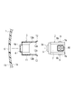
- FIG. 2 is a cross-sectional view of the above embodiment.
- FIG. 3 is an exploded cross-sectional view of the above embodiment.
- FIG. 1 shows the sonar sensor attached to the bumper as seen from the bumper surface side.
- FIG. 2 shows a cross section of a sonar sensor attached to a bumper via a holder.
- FIG. 3 shows a cross section of the holder and the sonar sensor before assembly to the bumper. 2 and 3, the side surface of the sonar sensor 2 is shown.
- a holder 5 having a cover portion 4 covering the detection surface 3 a of the sonar sensor 2 is fixed to the bumper 1.
- the bumper 1 is formed with a hole 6 into which the cover 4 that covers the detection surface 3a is inserted.
- the hole 6 is a circular hole penetrating in the bumper thickness direction.
- the outer surface 1b opposite to the inner surface 1a to which the sonar sensor 2 is attached is the outer side of the vehicle body.
- the outer surface 1b is painted.
- the sonar sensor 2 transmits an ultrasonic wave (ultrasound wave) H from the detection surface 3 a of the sensor body [sensor main body] 7 toward the detection object 8 and is reflected by the detection object 8. The reflected wave is received and the distance to the detection object 8 is detected.
- a lock claw [lock pawls] 9 (see FIG. 3) that prevents the sonar sensor 2 attached to the holder 4 from falling off is protruded from the side surface of the sensor body 7.
- the sonar sensor 2 attached by the lock claw 9 is held by the holder 4 so as not to easily fall off in the removal direction B opposite to the insertion direction A in FIG.
- the sensor body 7 is provided with a connector 10 for electrical connection with a controller (not shown).
- the connector 10 is connected to a connector attached to the front end of the body harness on the vehicle body side.
- the connector 10 is provided on one side of a rectangular or polygonal shape of the sensor body 7.
- the holder 5 is formed as a cylindrical case including the above-described cover portion 4 that covers the detection surface 3 a of the sonar sensor 2 and the holder main body 11 that surrounds the sensor main body 7.
- the cover part 4 has a low cylindrical shape covering the entire detection part 3 of the sonar sensor 2.
- the cover part 4 has a thickness that allows the ultrasonic wave H transmitted from the detection surface 3a of the sonar sensor 2 to pass therethrough [has a thickness enabling penetration of the ultrasound wave ...].
- an elastic material [elastic material] or an air layer [air] for acoustic separation is provided between the detection surface 3a as a vibration diaphragm and the cover portion 4. space] is provided.
- an internal space [internal chamber] that can accommodate the sensor body 7 is formed inside the holder body 11.
- the holder body 11 is formed with clip pieces [clipping tabs] 12 that engage with the lock claws 9 described above.
- the clip piece 12 has a hole 12b that engages with the rear end 9a of the lock claw 9 (see FIG. 3).
- a bent end [bent edge] 12a that is bent outward is formed at each edge of the clip piece 12 (see FIG. 3).
- the clip piece 12 can be elastically deformed.
- the sonar sensor 2 is attached to the holder 5, first, the front end inclined surface 9b of the lock claw 9 pushes the bent end 12a outward, and the clip piece 12 is elastically deformed outward.
- the clip piece 12 returns to its original shape by its own elastic restoring force, and the rear end 9a of the lock claw 9 and the hole 12b are engaged. .
- the hole 12b may be formed as a recess.
- the holder 5 has at least the cover 4 formed of the same resin material as that of the bumper 1. Of course, the entire holder 5 including the cover portion 4 may be formed of the same resin material as that of the bumper 1.
- the holder 5 configured in this way is fixed to the inner surface 1a from the inside of the bumper 1.
- various fixing methods using, for example, adhesive, welding, spray-bonding [spray-applied fixation] or screw fastening [screw fastening] can be applied.
- the holder 5 is fixed to the inner surface 1 a of the bumper 1. Specifically, first, the cover 4 of the holder 5 is inserted into the hole 6 from the inside of the bumper 1. At this time, the outer surface 4a of the cover part 4 is substantially flush with the outer surface 1b of the bumper 1 (forms a smooth continuous surface). In this state, the holder 5 is fixed to the inner surface 1a by the fixing method described above.
- the sonar sensor 2 is inserted into the holder 5 so that the detection unit 3 is housed in the cover unit 4.
- the detection unit 3 is covered with the cover unit 4, and the sensor body 7 is surrounded by the holder body 11. Further, the sonar sensor 2 is prevented from falling off the holder 5 by the engagement of the clip piece 12 and the lock claw 9.
- the cover 4 is interposed between the hole 6 and the detection unit 3 of the bumper 1, the gap between the hole 6 and the detection unit 3 is not visible (or almost invisible) from the outside, and the appearance is improved. Will improve.
- the conventional sonar sensor if the sonar sensor is mounted so that the detection unit and the bumper are in direct contact, the ultrasonic wave emitted from the detection surface propagates through the bumper to the detection surface of another adjacent sonar sensor and malfunctions. Cause. In order to prevent this malfunction, in the conventional sonar sensor, it is necessary to provide a gap between the detection unit and the bumper so that they do not directly contact each other.
- the gap is filled with the cover portion 4, the bumper 1 and the detection surface 3 a are not in direct contact with each other, and a gap that can be seen from the outside of the bumper 1 does not occur.
- the outer surface 4a of the cover part 4 and the outer surface 1b of the bumper 1 are painted with the same paint that coats the entire bumper 1.
- the holder 5 is attached to the bumper 1 in advance, and then the outer surface 1a of the bumper 1 and the outer surface 4a of the cover part 4 are coated with the same resin paint (painting process).
- the paint also enters the joint between the outer surface 1a of the bumper 1 and the outer surface 4a of the cover portion 4, the surface becomes more even, and is formed as a smoother continuous surface. Appearance is further improved. Further, it is possible to prevent rainwater from entering the seam from the seam.
- the color change with time of the paint is the same on the outer surface 1a of the bumper 1 and the outer surface 4a of the cover portion 4.
- the holder 5 is attached to the bumper 1 in advance, and then whether or not the outer surface 1a of the bumper 1 and the outer surface 4a of the cover part 4 are coated with the same resin paint (painting process) is observed by the relevant part after coating This makes it easy to distinguish.
- the holder 5 may be attached to the bumper 1 after the bumper 1 and the cover portion 4 are separately painted. Also in this case, the appearance of the appearance over time is improved.
- the bumper 1 of the holder 5 are formed of the same resin material, and the outer surface 4a of the cover part 4 and the outer surface 1b of the bumper 1 are painted with the same paint, the bumper 1 With one type of paint used for coating, both can be applied simultaneously in a single painting operation. For this reason, it is not necessary to adjust the color composition as in the case of painting with different types of paints, and the painting work is simplified. Even in the case of multilayer coating, the same painting process is performed on the outer surface 4a of the cover portion 4 and the outer surface 1b of the bumper 1 by the same paint, so that the painting operation is simplified.
- the cover portion 4 covering the detection surface 3a is inserted from the inside of the bumper 1, and the outer surface 1b of the bumper 1 and the outer surface 4a of the cover portion 4 are substantially flush with each other.
- the space between the inner edge and the inner edge is filled with the cover portion 4, and the gap is reduced. Therefore, since the gap visible from the outside of the bumper 1 is reduced, the appearance of the appearance is improved.
- the cover part 4 has a thickness through which the ultrasonic wave H transmitted from the detection surface 3a can pass, the function of the sonar sensor 2 is not hindered, and the sonar sensor 2 exhibits good performance. .
- a structure in which the sonar sensor 2 is inserted and held in the holder 5 is employed.
- the present invention can be applied to a sonar sensor mounting structure in which a sonar sensor is mounted on a bumper (resin member) of a vehicle or the like via a resin holder.
Landscapes
- Engineering & Computer Science (AREA)
- Physics & Mathematics (AREA)
- Radar, Positioning & Navigation (AREA)
- Remote Sensing (AREA)
- Computer Networks & Wireless Communication (AREA)
- General Physics & Mathematics (AREA)
- Mechanical Engineering (AREA)
- Acoustics & Sound (AREA)
- Measurement Of Velocity Or Position Using Acoustic Or Ultrasonic Waves (AREA)
Abstract
Priority Applications (4)
| Application Number | Priority Date | Filing Date | Title |
|---|---|---|---|
| EP12773645.2A EP2700975B1 (fr) | 2011-04-20 | 2012-02-24 | Structure de montage pour un capteur sonar |
| JP2013510914A JP5965391B2 (ja) | 2011-04-20 | 2012-02-24 | ソナーセンサの取付構造 |
| CN201280019514.0A CN103492901B (zh) | 2011-04-20 | 2012-02-24 | 声纳传感器的安装构造 |
| US14/112,480 US10254401B2 (en) | 2011-04-20 | 2012-02-24 | Mounting structure for sonar sensor |
Applications Claiming Priority (2)
| Application Number | Priority Date | Filing Date | Title |
|---|---|---|---|
| JP2011093813 | 2011-04-20 | ||
| JP2011-093813 | 2011-04-20 |
Publications (1)
| Publication Number | Publication Date |
|---|---|
| WO2012144270A1 true WO2012144270A1 (fr) | 2012-10-26 |
Family
ID=47041392
Family Applications (1)
| Application Number | Title | Priority Date | Filing Date |
|---|---|---|---|
| PCT/JP2012/054599 Ceased WO2012144270A1 (fr) | 2011-04-20 | 2012-02-24 | Structure de montage pour un capteur sonar |
Country Status (5)
| Country | Link |
|---|---|
| US (1) | US10254401B2 (fr) |
| EP (1) | EP2700975B1 (fr) |
| JP (1) | JP5965391B2 (fr) |
| CN (1) | CN103492901B (fr) |
| WO (1) | WO2012144270A1 (fr) |
Cited By (4)
| Publication number | Priority date | Publication date | Assignee | Title |
|---|---|---|---|---|
| WO2014136221A1 (fr) * | 2013-03-06 | 2014-09-12 | 三菱電機株式会社 | Dispositif de détection d'obstruction |
| JP6097988B1 (ja) * | 2016-06-22 | 2017-03-22 | 本多電子株式会社 | 超音波センサユニット及びその製造方法、超音波計測装置 |
| US11313965B2 (en) | 2017-11-28 | 2022-04-26 | Toyota Jidosha Kabushiki Kaisha | Sensor installation structure |
| JP2022162722A (ja) * | 2021-04-13 | 2022-10-25 | 株式会社ニフコ | センサの取付構造 |
Families Citing this family (13)
| Publication number | Priority date | Publication date | Assignee | Title |
|---|---|---|---|---|
| US10704021B2 (en) | 2012-03-15 | 2020-07-07 | Flodesign Sonics, Inc. | Acoustic perfusion devices |
| WO2015105955A1 (fr) | 2014-01-08 | 2015-07-16 | Flodesign Sonics, Inc. | Dispositif d'acoustophorèse avec double chambre acoustophorétique |
| CN105022065A (zh) * | 2014-04-30 | 2015-11-04 | 中兴通讯股份有限公司 | 终端及其测距的方法 |
| US11377651B2 (en) | 2016-10-19 | 2022-07-05 | Flodesign Sonics, Inc. | Cell therapy processes utilizing acoustophoresis |
| US11708572B2 (en) | 2015-04-29 | 2023-07-25 | Flodesign Sonics, Inc. | Acoustic cell separation techniques and processes |
| EP3118065B2 (fr) | 2015-07-13 | 2022-09-28 | SMP Deutschland GmbH | Composant d'habillage pour un vehicule et procede de fixation et d'alignement d'un logement de capteur sur un composant d'habillage |
| US11214789B2 (en) | 2016-05-03 | 2022-01-04 | Flodesign Sonics, Inc. | Concentration and washing of particles with acoustics |
| KR102439221B1 (ko) | 2017-12-14 | 2022-09-01 | 프로디자인 소닉스, 인크. | 음향 트랜스듀서 구동기 및 제어기 |
| JP7037998B2 (ja) * | 2018-04-19 | 2022-03-17 | 本田技研工業株式会社 | 輸送機器 |
| JP7024662B2 (ja) | 2018-08-24 | 2022-02-24 | 株式会社デンソー | リテーナ部材 |
| JP6830502B2 (ja) * | 2019-02-15 | 2021-02-17 | 本田技研工業株式会社 | センサ取付構造及びエネルギ吸収構造 |
| CN111907423B (zh) * | 2020-09-09 | 2025-03-25 | 珠海市多泰吉智能技术有限公司 | 传感器装置及汽车车门 |
| US12570230B2 (en) * | 2023-11-03 | 2026-03-10 | Robert Bosch Gmbh | Retainerless sensor mounting arrangement for a metal bumper |
Citations (3)
| Publication number | Priority date | Publication date | Assignee | Title |
|---|---|---|---|---|
| US6318774B1 (en) | 1997-05-09 | 2001-11-20 | Robert Bosch Gmbh | Modular device to be inserted into a vehicle bumper |
| JP2006203563A (ja) * | 2005-01-20 | 2006-08-03 | Nippon Soken Inc | 超音波センサ |
| US20070194892A1 (en) * | 2006-02-03 | 2007-08-23 | Gunther Schaaf | Sensor device for vehicles |
Family Cites Families (13)
| Publication number | Priority date | Publication date | Assignee | Title |
|---|---|---|---|---|
| DE19601987A1 (de) * | 1996-01-20 | 1997-07-24 | Teves Gmbh Alfred | Überlackierbarer Stoßfänger mit Ultraschallwandler |
| DE10039060A1 (de) | 2000-08-10 | 2002-03-07 | Rehau Ag & Co | Ultraschallwandler/Sensor zum Einbau in einen Stoßfänger eines Kraftfahrzeuges |
| DE10260118A1 (de) * | 2002-12-19 | 2004-07-01 | Valeo Schalter Und Sensoren Gmbh | Ultraschallsensor und Herstellungsverfahren |
| JP2004264264A (ja) | 2003-03-04 | 2004-09-24 | Matsushita Electric Works Ltd | 超音波センサ |
| JP4483672B2 (ja) * | 2005-04-15 | 2010-06-16 | 株式会社デンソー | 超音波センサの取付け構造 |
| JP2006345312A (ja) * | 2005-06-09 | 2006-12-21 | Denso Corp | 超音波センサ及び超音波振動子 |
| JP2007212349A (ja) * | 2006-02-10 | 2007-08-23 | Nippon Soken Inc | 障害物検出装置 |
| JP4752715B2 (ja) * | 2006-10-13 | 2011-08-17 | 株式会社デンソー | 超音波センサ |
| JP2008099102A (ja) * | 2006-10-13 | 2008-04-24 | Denso Corp | 超音波センサ |
| JP2008191007A (ja) * | 2007-02-05 | 2008-08-21 | Denso Corp | センサ装置の取り付け構造 |
| DE102007043500A1 (de) * | 2007-09-12 | 2009-03-19 | Valeo Schalter Und Sensoren Gmbh | Einbauanordnung für ein schwingungsempfindliches Bauteil, insbesondere eines Ultraschallwandlers, und Verfahren zum Einbau des Bauteils |
| JP5592079B2 (ja) * | 2009-04-28 | 2014-09-17 | 日本セラミック株式会社 | 超音波送受信器 |
| JP5406676B2 (ja) * | 2009-11-10 | 2014-02-05 | 株式会社ディスコ | ウエーハの加工装置 |
-
2012
- 2012-02-24 JP JP2013510914A patent/JP5965391B2/ja active Active
- 2012-02-24 US US14/112,480 patent/US10254401B2/en active Active
- 2012-02-24 EP EP12773645.2A patent/EP2700975B1/fr active Active
- 2012-02-24 WO PCT/JP2012/054599 patent/WO2012144270A1/fr not_active Ceased
- 2012-02-24 CN CN201280019514.0A patent/CN103492901B/zh active Active
Patent Citations (4)
| Publication number | Priority date | Publication date | Assignee | Title |
|---|---|---|---|---|
| US6318774B1 (en) | 1997-05-09 | 2001-11-20 | Robert Bosch Gmbh | Modular device to be inserted into a vehicle bumper |
| JP2001527480A (ja) | 1997-05-09 | 2001-12-25 | ローベルト ボツシユ ゲゼルシヤフト ミツト ベシユレンクテル ハフツング | 自動車のバンパに組み込むためのモジュールを備えた装置 |
| JP2006203563A (ja) * | 2005-01-20 | 2006-08-03 | Nippon Soken Inc | 超音波センサ |
| US20070194892A1 (en) * | 2006-02-03 | 2007-08-23 | Gunther Schaaf | Sensor device for vehicles |
Non-Patent Citations (1)
| Title |
|---|
| See also references of EP2700975A4 |
Cited By (7)
| Publication number | Priority date | Publication date | Assignee | Title |
|---|---|---|---|---|
| WO2014136221A1 (fr) * | 2013-03-06 | 2014-09-12 | 三菱電機株式会社 | Dispositif de détection d'obstruction |
| JPWO2014136221A1 (ja) * | 2013-03-06 | 2017-02-09 | 三菱電機株式会社 | 障害物検知装置 |
| JP6097988B1 (ja) * | 2016-06-22 | 2017-03-22 | 本多電子株式会社 | 超音波センサユニット及びその製造方法、超音波計測装置 |
| WO2017221340A1 (fr) * | 2016-06-22 | 2017-12-28 | 本多電子株式会社 | Unité de capteur ultrasonore, son procédé de fabrication et dispositif de mesure ultrasonore |
| US11313965B2 (en) | 2017-11-28 | 2022-04-26 | Toyota Jidosha Kabushiki Kaisha | Sensor installation structure |
| JP2022162722A (ja) * | 2021-04-13 | 2022-10-25 | 株式会社ニフコ | センサの取付構造 |
| JP7551562B2 (ja) | 2021-04-13 | 2024-09-17 | 株式会社ニフコ | センサの取付構造 |
Also Published As
| Publication number | Publication date |
|---|---|
| JP5965391B2 (ja) | 2016-08-03 |
| EP2700975B1 (fr) | 2023-04-05 |
| EP2700975A4 (fr) | 2015-04-15 |
| CN103492901A (zh) | 2014-01-01 |
| US20140036632A1 (en) | 2014-02-06 |
| CN103492901B (zh) | 2017-11-21 |
| EP2700975A1 (fr) | 2014-02-26 |
| US10254401B2 (en) | 2019-04-09 |
| JPWO2012144270A1 (ja) | 2014-07-28 |
Similar Documents
| Publication | Publication Date | Title |
|---|---|---|
| JP5965391B2 (ja) | ソナーセンサの取付構造 | |
| CN107850665B (zh) | 用于布置在车辆的覆盖构件上的超声波传感器设备 | |
| CN104641252B (zh) | 具有改进的脱离环的超声传感器装置和机动车辆 | |
| US9910142B2 (en) | Ultrasonic sensor device comprising a reinforcement holder, arrangement, motor vehicle and corresponding method | |
| CN106257304B (zh) | 低反射雷达支架 | |
| US6941714B2 (en) | Grommet | |
| CN103502840B (zh) | 超声波传感器 | |
| JP2001527480A (ja) | 自動車のバンパに組み込むためのモジュールを備えた装置 | |
| JP4839587B2 (ja) | 超音波センサの取付け構造 | |
| CN104246533B (zh) | 车辆用超声波传感器装置以及车辆用超声波传感器装置的组装方法 | |
| JP4869814B2 (ja) | ドアライニングの固定構造および固定方法 | |
| CN106061629B (zh) | 用于制造用于机动车辆的超声波传感器的方法 | |
| US8910986B1 (en) | Bonded and rotatable vehicle sensor assembly | |
| US20090013782A1 (en) | Sensor Mount, in Particular for Mounting Inter-Vehicle Distance Sensors on Vehicle Components | |
| US11130460B2 (en) | Sensor protector | |
| CN103733250B (zh) | 用于交通运输工具的超声波传感器装置以及带有此类超声波传感器装置的装置 | |
| JP2001063497A (ja) | 超音波センサの取り付け構造 | |
| JP2022158504A (ja) | 車両構造 | |
| EP3339105B1 (fr) | Ensemble capteur à ultrasons et ensemble de montage | |
| JP4831182B2 (ja) | 塗装方法並びに塗装用冶具 | |
| JP3659153B2 (ja) | 超音波振動子 | |
| JP6593839B2 (ja) | インストルメントパネル構造 | |
| JP2014129014A (ja) | 金属バンパ用樹脂スペーサ及びセンサの取り付け構造 | |
| US20250334685A1 (en) | Ultrasonic sensor | |
| WO2014136221A1 (fr) | Dispositif de détection d'obstruction |
Legal Events
| Date | Code | Title | Description |
|---|---|---|---|
| 121 | Ep: the epo has been informed by wipo that ep was designated in this application |
Ref document number: 12773645 Country of ref document: EP Kind code of ref document: A1 |
|
| WWE | Wipo information: entry into national phase |
Ref document number: 2012773645 Country of ref document: EP |
|
| ENP | Entry into the national phase |
Ref document number: 2013510914 Country of ref document: JP Kind code of ref document: A |
|
| WWE | Wipo information: entry into national phase |
Ref document number: 14112480 Country of ref document: US |
|
| NENP | Non-entry into the national phase |
Ref country code: DE |