WO2012144272A1 - Capteur de déformation à fbg - Google Patents
Capteur de déformation à fbg Download PDFInfo
- Publication number
- WO2012144272A1 WO2012144272A1 PCT/JP2012/054647 JP2012054647W WO2012144272A1 WO 2012144272 A1 WO2012144272 A1 WO 2012144272A1 JP 2012054647 W JP2012054647 W JP 2012054647W WO 2012144272 A1 WO2012144272 A1 WO 2012144272A1
- Authority
- WO
- WIPO (PCT)
- Prior art keywords
- fbg
- temperature compensation
- compensation member
- optical fiber
- measured
- Prior art date
- Legal status (The legal status is an assumption and is not a legal conclusion. Google has not performed a legal analysis and makes no representation as to the accuracy of the status listed.)
- Ceased
Links
Images


Classifications
-
- G—PHYSICS
- G01—MEASURING; TESTING
- G01B—MEASURING LENGTH, THICKNESS OR SIMILAR LINEAR DIMENSIONS; MEASURING ANGLES; MEASURING AREAS; MEASURING IRREGULARITIES OF SURFACES OR CONTOURS
- G01B5/00—Measuring arrangements characterised by the use of mechanical techniques
- G01B5/0011—Arrangements for eliminating or compensation of measuring errors due to temperature or weight
- G01B5/0014—Arrangements for eliminating or compensation of measuring errors due to temperature or weight due to temperature
-
- G—PHYSICS
- G01—MEASURING; TESTING
- G01B—MEASURING LENGTH, THICKNESS OR SIMILAR LINEAR DIMENSIONS; MEASURING ANGLES; MEASURING AREAS; MEASURING IRREGULARITIES OF SURFACES OR CONTOURS
- G01B11/00—Measuring arrangements characterised by the use of optical techniques
- G01B11/16—Measuring arrangements characterised by the use of optical techniques for measuring the deformation in a solid, e.g. optical strain gauge
- G01B11/18—Measuring arrangements characterised by the use of optical techniques for measuring the deformation in a solid, e.g. optical strain gauge using photoelastic elements
-
- G—PHYSICS
- G01—MEASURING; TESTING
- G01D—MEASURING NOT SPECIALLY ADAPTED FOR A SPECIFIC VARIABLE; ARRANGEMENTS FOR MEASURING TWO OR MORE VARIABLES NOT COVERED IN A SINGLE OTHER SUBCLASS; TARIFF METERING APPARATUS; MEASURING OR TESTING NOT OTHERWISE PROVIDED FOR
- G01D5/00—Mechanical means for transferring the output of a sensing member; Means for converting the output of a sensing member to another variable where the form or nature of the sensing member does not constrain the means for converting; Transducers not specially adapted for a specific variable
- G01D5/26—Mechanical means for transferring the output of a sensing member; Means for converting the output of a sensing member to another variable where the form or nature of the sensing member does not constrain the means for converting; Transducers not specially adapted for a specific variable characterised by optical transfer means, i.e. using infrared, visible, or ultraviolet light
- G01D5/32—Mechanical means for transferring the output of a sensing member; Means for converting the output of a sensing member to another variable where the form or nature of the sensing member does not constrain the means for converting; Transducers not specially adapted for a specific variable characterised by optical transfer means, i.e. using infrared, visible, or ultraviolet light with attenuation or whole or partial obturation of beams of light
- G01D5/34—Mechanical means for transferring the output of a sensing member; Means for converting the output of a sensing member to another variable where the form or nature of the sensing member does not constrain the means for converting; Transducers not specially adapted for a specific variable characterised by optical transfer means, i.e. using infrared, visible, or ultraviolet light with attenuation or whole or partial obturation of beams of light the beams of light being detected by photocells
- G01D5/353—Mechanical means for transferring the output of a sensing member; Means for converting the output of a sensing member to another variable where the form or nature of the sensing member does not constrain the means for converting; Transducers not specially adapted for a specific variable characterised by optical transfer means, i.e. using infrared, visible, or ultraviolet light with attenuation or whole or partial obturation of beams of light the beams of light being detected by photocells influencing the transmission properties of an optical fibre
- G01D5/35303—Mechanical means for transferring the output of a sensing member; Means for converting the output of a sensing member to another variable where the form or nature of the sensing member does not constrain the means for converting; Transducers not specially adapted for a specific variable characterised by optical transfer means, i.e. using infrared, visible, or ultraviolet light with attenuation or whole or partial obturation of beams of light the beams of light being detected by photocells influencing the transmission properties of an optical fibre using a reference fibre, e.g. interferometric devices
-
- G—PHYSICS
- G01—MEASURING; TESTING
- G01D—MEASURING NOT SPECIALLY ADAPTED FOR A SPECIFIC VARIABLE; ARRANGEMENTS FOR MEASURING TWO OR MORE VARIABLES NOT COVERED IN A SINGLE OTHER SUBCLASS; TARIFF METERING APPARATUS; MEASURING OR TESTING NOT OTHERWISE PROVIDED FOR
- G01D5/00—Mechanical means for transferring the output of a sensing member; Means for converting the output of a sensing member to another variable where the form or nature of the sensing member does not constrain the means for converting; Transducers not specially adapted for a specific variable
- G01D5/26—Mechanical means for transferring the output of a sensing member; Means for converting the output of a sensing member to another variable where the form or nature of the sensing member does not constrain the means for converting; Transducers not specially adapted for a specific variable characterised by optical transfer means, i.e. using infrared, visible, or ultraviolet light
- G01D5/32—Mechanical means for transferring the output of a sensing member; Means for converting the output of a sensing member to another variable where the form or nature of the sensing member does not constrain the means for converting; Transducers not specially adapted for a specific variable characterised by optical transfer means, i.e. using infrared, visible, or ultraviolet light with attenuation or whole or partial obturation of beams of light
- G01D5/34—Mechanical means for transferring the output of a sensing member; Means for converting the output of a sensing member to another variable where the form or nature of the sensing member does not constrain the means for converting; Transducers not specially adapted for a specific variable characterised by optical transfer means, i.e. using infrared, visible, or ultraviolet light with attenuation or whole or partial obturation of beams of light the beams of light being detected by photocells
- G01D5/353—Mechanical means for transferring the output of a sensing member; Means for converting the output of a sensing member to another variable where the form or nature of the sensing member does not constrain the means for converting; Transducers not specially adapted for a specific variable characterised by optical transfer means, i.e. using infrared, visible, or ultraviolet light with attenuation or whole or partial obturation of beams of light the beams of light being detected by photocells influencing the transmission properties of an optical fibre
- G01D5/35306—Mechanical means for transferring the output of a sensing member; Means for converting the output of a sensing member to another variable where the form or nature of the sensing member does not constrain the means for converting; Transducers not specially adapted for a specific variable characterised by optical transfer means, i.e. using infrared, visible, or ultraviolet light with attenuation or whole or partial obturation of beams of light the beams of light being detected by photocells influencing the transmission properties of an optical fibre using an interferometer arrangement
- G01D5/35309—Mechanical means for transferring the output of a sensing member; Means for converting the output of a sensing member to another variable where the form or nature of the sensing member does not constrain the means for converting; Transducers not specially adapted for a specific variable characterised by optical transfer means, i.e. using infrared, visible, or ultraviolet light with attenuation or whole or partial obturation of beams of light the beams of light being detected by photocells influencing the transmission properties of an optical fibre using an interferometer arrangement using multiple waves interferometer
- G01D5/35316—Mechanical means for transferring the output of a sensing member; Means for converting the output of a sensing member to another variable where the form or nature of the sensing member does not constrain the means for converting; Transducers not specially adapted for a specific variable characterised by optical transfer means, i.e. using infrared, visible, or ultraviolet light with attenuation or whole or partial obturation of beams of light the beams of light being detected by photocells influencing the transmission properties of an optical fibre using an interferometer arrangement using multiple waves interferometer using a Bragg gratings
-
- G—PHYSICS
- G01—MEASURING; TESTING
- G01L—MEASURING FORCE, STRESS, TORQUE, WORK, MECHANICAL POWER, MECHANICAL EFFICIENCY, OR FLUID PRESSURE
- G01L1/00—Measuring force or stress, in general
- G01L1/24—Measuring force or stress, in general by measuring variations of optical properties of material when it is stressed, e.g. by photoelastic stress analysis using infrared, visible light, ultraviolet
- G01L1/242—Measuring force or stress, in general by measuring variations of optical properties of material when it is stressed, e.g. by photoelastic stress analysis using infrared, visible light, ultraviolet the material being an optical fibre
- G01L1/246—Measuring force or stress, in general by measuring variations of optical properties of material when it is stressed, e.g. by photoelastic stress analysis using infrared, visible light, ultraviolet the material being an optical fibre using integrated gratings, e.g. Bragg gratings
-
- G—PHYSICS
- G01—MEASURING; TESTING
- G01L—MEASURING FORCE, STRESS, TORQUE, WORK, MECHANICAL POWER, MECHANICAL EFFICIENCY, OR FLUID PRESSURE
- G01L1/00—Measuring force or stress, in general
- G01L1/26—Auxiliary measures taken, or devices used, in connection with the measurement of force, e.g. for preventing influence of transverse components of force, for preventing overload
Definitions
- the present invention relates to an FBG strain sensor that measures the strain amount of an object to be measured, and more particularly, to a configuration for performing temperature compensation according to the ambient temperature at the time of measurement.
- an FBG strain sensor using an FBG is used as a strain sensor for measuring a strain amount.
- the FBG is a diffraction grating in which the refractive index of the core of the optical fiber is changed by a predetermined length period (grating period) along the axial direction, and the incident light to the optical fiber depends on the grating period. Only light of a specific wavelength (Bragg wavelength) is reflected, and the remaining light is transmitted. When distortion occurs in the FBG, the grating period changes, and the Bragg wavelength also changes accordingly. Therefore, the amount of distortion can be measured based on the amount of change in the Bragg wavelength.
- the optical fiber thermally expands according to the ambient temperature, which is the ambient temperature at the time of measuring the strain, and the grating period also changes accordingly. Therefore, the Bragg wavelength of the FBG also changes according to the ambient temperature. Have. Therefore, in order to measure an accurate strain amount of the object to be measured, it is necessary to perform temperature compensation according to the ambient temperature.
- Patent Document 1 discloses an optical fiber sensor that performs temperature compensation using two FBGs formed as detection element portions.
- one of the FBGs is provided for close contact with a liquid crystal polymer substrate fixed to a steel cord that is an object to be measured, for measuring the amount of strain.
- the other side of the FBG is provided for temperature compensation in a relaxed state with respect to the liquid crystal polymer substrate.
- the Bragg wavelength of the strain measurement FBG varies depending on the strain amount of the steel cord applied through the liquid crystal polymer substrate and the thermal expansion amount of the optical fiber according to the ambient temperature.
- the strain amount of the steel cord is not applied to the relaxed temperature compensating FBG, its Bragg wavelength changes due to the amount of thermal expansion of the optical fiber according to the ambient temperature.
- the sensor described in Patent Document 1 performs temperature compensation by subtracting the change amount of the Bragg wavelength of the temperature compensation FBG from the change amount of the Bragg wavelength of the strain amount measurement FBG, and measures the strain amount of the steel cord.
- These two FBGs can be arranged in series or in parallel, and when arranged in series, two FBGs are formed in one optical fiber.
- two optical fibers that is, an optical fiber on which a strain amount measuring FBG is formed and an optical fiber on which a temperature compensating FBG is formed are provided on a liquid crystal polymer substrate.
- the optical fiber sensor described in Patent Document 1 requires two FBGs for strain amount measurement and temperature compensation, the entire sensor can be downsized or the configuration of the entire sensor can be simplified. Has the problem of being difficult. Specifically, when two FBGs are arranged in series in the optical fiber sensor described in Patent Document 1, the length dimension along the axial direction of the portion where the FBGs are arranged is inevitably large. It becomes difficult to reduce the size. Also, when two FBGs are arranged in parallel, two optical fibers are provided on the liquid crystal polymer substrate, so that it is necessary to supply incident light and detect reflected light to the two optical fibers, respectively. The configuration of the entire sensor becomes complicated.
- the present invention has been made to solve such problems, and has an object to provide an FBG strain sensor that realizes temperature compensation with a simple configuration without increasing the size of the entire sensor. To do.
- An FBG strain sensor includes an optical fiber having an FBG that changes a wavelength of reflected light with respect to incident light and a wavelength of transmitted light with respect to incident light in accordance with the amount of strain applied from the measurement target part.
- An FBG strain sensor that measures the amount of strain of a measured portion based on the amount of change in the wavelength of light or the amount of change in the wavelength of transmitted light, wherein the FBG is fixed to one surface and the other surface is measured And a temperature compensating member that is fixable to the temperature compensation member.
- the FBG strain sensor can be applied to a vehicle sensor that detects a vehicle collision.
- the vehicle sensor in this case has a plurality of FBGs in which the vehicle has a plurality of parts to be measured, and an optical fiber is provided in the plurality of parts to be measured, and corresponding FBGs from at least one of the plurality of parts to be measured. A vehicle collision is detected based on the amount of strain applied to the vehicle.
- temperature compensation in a strain sensor using FBG, temperature compensation can be performed with a simple configuration without increasing the size of the entire sensor.
- FIG. 3 is a schematic diagram illustrating a configuration of an FBG in the FBG strain sensor according to the first embodiment. It is the schematic which shows the structure of the vehicle sensor using the FBG sensor which concerns on Embodiment 2 of this invention.
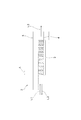
- FIG. 1 schematically shows an FBG strain sensor 1 according to Embodiment 1 of the present invention.
- the FBG strain sensor 1 is a sensor that measures strain generated in the measurement target W using an optical fiber 2, and light emitted from a light source (not shown) is incident from one end side of the optical fiber 2.
- the optical fiber 2 has an FBG (fiber Bragg grating) 3 that reflects light having a specific wavelength called a Bragg wavelength with respect to incident light from the light source. Arranged on the side.
- FBG fiber Bragg grating
- the optical fiber 2 is formed of quartz glass or the like, and includes a core 4 through which incident light L1 from a light source (not shown) propagates, and a cladding 5 that covers the outer periphery of the core 4. ing.
- the FBG 3 is a diffraction grating in which the refractive index of the core 4 is changed by a length period ⁇ along the axial direction, that is, a grating period ⁇ .
- the FBG 3 reflects only light having a Bragg wavelength with respect to the incident light L1 as reflected light L2. The remaining light is transmitted as transmitted light L3.
- the length period ⁇ in the FBG 3 is one of the elements that define the wavelength (Bragg wavelength) of the reflected light L2, and when an axial distortion occurs in the FBG 3 and the grating period ⁇ is changed, The Bragg wavelength also changes. That is, the strain amount of the FBG 3 can be measured based on the amount of change of the Bragg wavelength before and after the occurrence of strain, specifically, the shift amount of the center wavelength of the reflected light L2.
- the FBG 3 is formed by irradiating the core 4 of the optical fiber 2 with ultraviolet rays or the like.
- the FBG strain sensor 1 includes a flat plate-shaped temperature compensation member 11 provided between the optical fiber 2 and the part to be measured W.
- the optical fiber 2 passes through the temperature compensation member 11.
- the temperature compensation member 11 is formed in a rectangular shape with the direction indicated by the arrow A in FIG. 1 as the longitudinal direction, and the optical fiber 2 is fixed to the upper surface 11a, which is one surface thereof, and the other surface is A certain lower surface 11b side can be fixed to the part to be measured W. Further, the temperature compensation member 11 is arranged so that the longitudinal direction (see arrow A) and the longitudinal direction of the optical fiber 2 are along each other, and the FBG 3 is located at substantially the center of the upper surface 11a of the temperature compensation member 11. ing.
- the optical fiber 2 and the upper surface 11a of the temperature compensation member 11 are fixed by the adhesive 12 over the entire surface where they abut.
- the lower surface 11b of the temperature compensation member 11 is fixed to the upper surface Wa of the part to be measured W by the adhesive 13 at two locations along the longitudinal direction. Therefore, when distortion occurs in the measurement target W in the direction indicated by the arrow A, the distortion is applied to the temperature compensation member 11 via the adhesive 13 at two locations. Further, since the optical fiber 2 is entirely bonded to the upper surface 11a of the temperature compensation member 11, the strain applied to the temperature compensation member 11 from the measurement target portion W is directly applied to the FBG 3. ing.
- the pair of adhesives 13 provided on the lower surface 11b of the temperature compensation member 11 are arranged such that the distance d1 is equal to or longer than the length d2 of the FBG 3, and the FBG 3 is attached to the upper surface 11a. It arrange
- the temperature compensation member 11 is made of glass having a coefficient of thermal expansion of zero, so that the temperature compensation member 11 does not expand due to changes in the ambient temperature.
- the optical fiber 2 has a positive coefficient of thermal expansion, and is expanded and contracted by thermal expansion accompanying a change in ambient temperature.
- the Bragg wavelength that is the wavelength of the reflected light L2 from the FBG 3 is defined by the grating period ⁇ of the FBG 3. Therefore, when the optical fiber 2 expands and contracts according to the ambient temperature, the grating period ⁇ of the FBG 3 also changes accordingly, so that the Bragg wavelength changes.
- the coefficient of thermal expansion is not limited to the case where the coefficient of thermal expansion is almost zero as in the case of zero thermal expansion glass, but refers to the case where the coefficient of thermal expansion is almost zero. Including a case where is not more than ⁇ 1 ⁇ 10 ⁇ 6 / ° C.
- the optical fiber 2 is fixed to the temperature compensation member 11 having a thermal expansion coefficient of zero by the adhesive 12 over the entire surface where the optical fiber 2 abuts, the expansion and contraction of the FBG 3 is constrained by the temperature compensation member 11. It has become. That is, since the thermal expansion of the FBG 3 according to the ambient temperature is suppressed by the temperature compensation member 11 that does not cause thermal expansion, only the strain of the part to be measured W is applied to the FBG 3 regardless of the ambient temperature. It has become.
- the optical fiber 2 in the first embodiment has been described as having a positive thermal expansion coefficient, the effect of suppressing the thermal expansion of the FBG 3 by the temperature compensation member 11 is that the optical fiber 2 has a negative thermal expansion coefficient. The same applies to the case of having. Further, the coefficient of thermal expansion of the temperature compensation member 11 can be made zero by adjusting manufacturing conditions such as preparation of glass components as materials.
- the FBG strain sensor 1 is fixed to the upper surface Wa of the part W to be measured by the adhesive 13 applied to both ends of the lower surface 11 b of the temperature compensation member 11.
- a light source (not shown) is connected to one end side of the optical fiber 2.
- a measuring instrument (not shown) to which the reflected light L2 from the FBG 3 (see FIG. 2) is input is connected to one end side of the optical fiber 2. This measuring device calculates the amount of distortion of the portion to be measured W based on the amount of change in the reflected light L2 before and after the occurrence of strain at the portion to be measured W, that is, the amount of shift of the Bragg wavelength.
- the FBG strain sensor 1 When the FBG strain sensor 1 is fixed to the measurement target W, incident light L1 is incident on the optical fiber 2 from a light source (not shown).
- the FBG 3 reflects Bragg wavelength light as reflected light L2 with respect to the incident light L1, and transmits the remaining light as transmitted light L3 (see FIG. 2).
- the agent 12 is sequentially applied to the FBG 3.
- the strain of the part to be measured W is applied to the FBG 3 and the FBG 3 expands, the grating period ⁇ (see FIG. 2) of the FBG 3 also expands, so the wavelength of the reflected light L2 (Bragg wavelength) also changes.
- the optical fiber 2 since the optical fiber 2 has a positive coefficient of thermal expansion, the optical fiber 2 tends to expand in the direction along the longitudinal direction A by thermal expansion corresponding to the ambient temperature at the time of strain measurement.
- the optical fiber 2 since the optical fiber 2 is fixed to the temperature compensation member 11 having a thermal expansion coefficient of zero on the entire surface in contact with the temperature compensation member 11, and the expansion and contraction of the FBG 3 is restricted by the temperature compensation member 11, the extension of the FBG 3 is performed. Is suppressed. Therefore, the FBG 3 is in a state in which temperature compensation is performed with respect to the ambient temperature, that is, the Bragg wavelength shift due to thermal expansion of the FBG 3 does not occur, and the Bragg wavelength is shifted only by the strain of the measurement target W. Therefore, the strain amount of the part W to be measured is measured without error due to the ambient temperature.
- the temperature compensation member 11 is provided between the part to be measured W and the FBG 3 of the optical fiber 2, strain generated in the part to be measured W is applied to the FBG 3 via the temperature compensation member 11. Since the temperature compensation member 11 is formed of a material having a coefficient of thermal expansion of zero, it does not thermally expand according to the ambient temperature when measuring the strain amount. Since the FBG 3 is fixed to such a temperature compensation member 11, the FBG 3 is constrained by the temperature compensation member 11, and the thermal expansion of the FBG 3 according to the ambient temperature is suppressed.
- the FBG strain sensor 1 can perform temperature compensation with a simple configuration without increasing the size of the entire sensor.
- the temperature compensation member 11 is a flat plate member, the configuration of the FBG strain sensor 1 becomes simpler and the size in the height direction can be suppressed, so that the entire sensor can be further downsized.
- Embodiment 2 an FBG strain sensor according to Embodiment 2 of the present invention will be described.
- the FBG strain sensor according to the second embodiment is applied as a vehicle sensor that detects a vehicle collision.
- the same reference numerals as those shown in FIGS. 1 and 2 are the same or similar components, and thus detailed description thereof is omitted.
- the vehicle sensor 21 detects a collision of the vehicle 30 in order to operate a device such as an air bag, for example.
- a portion to be measured W is provided at a plurality of locations such as both sides of the rear portion.
- a single optical fiber 2 is routed inside the body 31 so as to pass through each measured portion W, and the optical fiber 2 is installed at a plurality of locations corresponding to each measured portion W. It has FBG3 similar to the form 1.
- Each FBG 3 is fixed to a temperature compensation member 11 attached to the part W to be measured, and the FBG 3 and the temperature compensation member 11 form a sensor unit 22.
- Each sensor unit 22 has the same configuration as the FBG strain sensor 1 shown in FIG. That is, the vehicle sensor 21 is obtained by installing the FBG strain sensor 1 according to the first embodiment on each measured portion W of the body 31 and connecting them via a single optical fiber 2.
- a light source (not shown) and a detection unit (not shown) for detecting a change in Bragg wavelength are connected to one end of the optical fiber 2. Further, the detection unit is electrically connected to a control unit (not shown) of the vehicle 30 and can output a detection result of the Bragg wavelength to the control unit.
- the control unit determines that the vehicle 30 has collided and activates the airbag or the like.
- temperature compensation is performed with respect to the ambient temperature as in the FBG strain sensor 1 in the first embodiment, so that malfunction does not occur due to a temperature change in the vehicle 30.
- the vehicle 30 can be compensated for temperature only by drawing one optical fiber 2 into the vehicle 30. Therefore, the vehicle sensor 21 can be constructed with a simple configuration. In addition, each sensor unit can be reduced in size as in the first embodiment, and therefore can be easily installed in a narrow place in the vehicle 30.
- Each sensor in the first and second embodiments is configured to measure the strain amount of the measurement target W based on the change amount of the wavelength of the reflected light L2 from the FBG 3, but is not limited to this configuration. It is also possible to measure the amount of strain based on the amount of change in the wavelength of the transmitted light L3. Since the transmitted light L3 is obtained by removing the reflected light L2 from the incident light L1 incident on the optical fiber 2, the amount of shift of the Bragg wavelength can be obtained from the transmitted light L3. Therefore, even when the strain amount is measured based on the transmitted light L3, the same effect as in the first and second embodiments can be obtained.
- a light source is connected to one end side of the optical fiber 2, and a measuring instrument is connected to the other end side.
- the shape of the temperature compensation member 11 is not limited. What is necessary is just to be able to apply the distortion amount of the to-be-measured part W to FBG3, for example, it can be set as polygonal shapes, such as a square which does not have a longitudinal direction, circular shapes, etc.
- the temperature compensation member is not limited to a plate-like member, and may be a cylindrical member or a rod-like member, for example. Even in this case, strain measurement and temperature compensation can be performed on a single measurement target W with a single FBG, so that temperature compensation can be performed with a simple configuration without increasing the size of the entire sensor. It becomes.
- the portion to be measured W in Embodiment 1 is shown in FIG. 1 as a rectangular member, the shape of the portion to be measured W is not limited, and the FBG strain sensor according to the present invention is the portion to be measured W. It is not limited to including.
- the present invention relates to an FBG strain sensor that can be fixed to a part to be measured, and may be an FBG strain sensor in a state before being fixed to the part to be measured.
- the temperature compensation member 11 in the first and second embodiments is fixed to the measured portion W by the pair of adhesives 13 applied to both ends thereof, but the temperature compensation member 11 and the measured portion W are bonded to each other. It is not limited to performing by these, and fixing these in two places used as the both ends of a temperature compensation member. What is necessary is just to be able to fix so that the distortion which arises in the to-be-measured part W is applied to the temperature compensation member 11, for example, using other fixing methods, such as welding, or fixing in two or more places including parts other than both ends. Is possible.
Landscapes
- Physics & Mathematics (AREA)
- General Physics & Mathematics (AREA)
- Length Measuring Devices By Optical Means (AREA)
- Optical Transform (AREA)
Abstract
La présente invention concerne un capteur de déformation à FBG qui permet une compensation de température au moyen d'une configuration simple, sans que la taille du capteur augmente. Le capteur de déformation à FBG (1) comprend une fibre optique (2) dans laquelle un FBG (3) est formé et un élément de compensation de température (11) servant à fixer la fibre optique (2) à une section à mesurer (W). La fibre optique (2) et l'élément de compensation de température (11) sont fixés par un adhésif (12) sur toute la surface avec laquelle ils sont en contact. Par ailleurs, l'élément de compensation de température (11) et la section à mesurer (W) sont fixés par un adhésif (13) aux deux sections terminales de l'élément de compensation de température (11). L'élément de compensation de température (11) est formé à partir d'un matériau possédant un coefficient de dilatation thermique qui est nul et la dilatation et la contraction du FBG (3) sont restreintes par l'élément de compensation de température (11). Par conséquent, la dilatation thermique du FBG (3) en réponse à la température ambiante est supprimée par l'élément de compensation de température (11) et seule la déformation ayant lieu dans la section à mesurer (W) est appliquée au FBG (3).
Applications Claiming Priority (2)
| Application Number | Priority Date | Filing Date | Title |
|---|---|---|---|
| JP2011-092741 | 2011-04-19 | ||
| JP2011092741A JP2012225729A (ja) | 2011-04-19 | 2011-04-19 | Fbgひずみセンサ |
Publications (1)
| Publication Number | Publication Date |
|---|---|
| WO2012144272A1 true WO2012144272A1 (fr) | 2012-10-26 |
Family
ID=47041394
Family Applications (1)
| Application Number | Title | Priority Date | Filing Date |
|---|---|---|---|
| PCT/JP2012/054647 Ceased WO2012144272A1 (fr) | 2011-04-19 | 2012-02-24 | Capteur de déformation à fbg |
Country Status (2)
| Country | Link |
|---|---|
| JP (1) | JP2012225729A (fr) |
| WO (1) | WO2012144272A1 (fr) |
Cited By (3)
| Publication number | Priority date | Publication date | Assignee | Title |
|---|---|---|---|---|
| CN106289088A (zh) * | 2016-07-27 | 2017-01-04 | 四川大学 | 应用于工程材料的补偿应变测试方法 |
| CN111811408A (zh) * | 2020-07-06 | 2020-10-23 | 天津求实飞博科技有限公司 | 一种应变系数自适应矿用围岩光纤位移传感器 |
| CN116067298A (zh) * | 2023-04-06 | 2023-05-05 | 山东省科学院激光研究所 | 一种光纤应变传感器结构 |
Families Citing this family (3)
| Publication number | Priority date | Publication date | Assignee | Title |
|---|---|---|---|---|
| KR101657776B1 (ko) * | 2014-10-15 | 2016-10-04 | (주)제이엠솔루션 | 자동차 내부 통신망을 연동한 차량용 충격 센싱 장치 |
| EP3425343B1 (fr) | 2016-03-01 | 2024-11-27 | Cmiws Co., Ltd. | Capteur à fibre optique |
| CN109373922A (zh) * | 2018-11-16 | 2019-02-22 | 中国铁路广州局集团有限公司 | 一种高铁站房光纤光栅温度补偿应变传感器 |
Citations (7)
| Publication number | Priority date | Publication date | Assignee | Title |
|---|---|---|---|---|
| JPH1073740A (ja) * | 1996-06-13 | 1998-03-17 | Corning Inc | 光学装置およびその製造方法 |
| JP2000111319A (ja) * | 1998-09-30 | 2000-04-18 | Ntt Advanced Technology Corp | 光ファイバセンサ |
| JP2004226546A (ja) * | 2003-01-21 | 2004-08-12 | Nippon Sheet Glass Co Ltd | 光ファイバ回折格子を用いた光学装置 |
| WO2005028995A1 (fr) * | 2003-09-17 | 2005-03-31 | Kyocera Corporation | Systeme de detection fbg |
| JP2005214824A (ja) * | 2004-01-30 | 2005-08-11 | Denso Corp | 光ファイバセンサ装置 |
| JP2005321223A (ja) * | 2004-05-06 | 2005-11-17 | Kawasaki Heavy Ind Ltd | 構造体および損傷検知装置 |
| JP2009059582A (ja) * | 2007-08-31 | 2009-03-19 | Toyota Motor Corp | 二次電池の圧力検出装置 |
-
2011
- 2011-04-19 JP JP2011092741A patent/JP2012225729A/ja active Pending
-
2012
- 2012-02-24 WO PCT/JP2012/054647 patent/WO2012144272A1/fr not_active Ceased
Patent Citations (7)
| Publication number | Priority date | Publication date | Assignee | Title |
|---|---|---|---|---|
| JPH1073740A (ja) * | 1996-06-13 | 1998-03-17 | Corning Inc | 光学装置およびその製造方法 |
| JP2000111319A (ja) * | 1998-09-30 | 2000-04-18 | Ntt Advanced Technology Corp | 光ファイバセンサ |
| JP2004226546A (ja) * | 2003-01-21 | 2004-08-12 | Nippon Sheet Glass Co Ltd | 光ファイバ回折格子を用いた光学装置 |
| WO2005028995A1 (fr) * | 2003-09-17 | 2005-03-31 | Kyocera Corporation | Systeme de detection fbg |
| JP2005214824A (ja) * | 2004-01-30 | 2005-08-11 | Denso Corp | 光ファイバセンサ装置 |
| JP2005321223A (ja) * | 2004-05-06 | 2005-11-17 | Kawasaki Heavy Ind Ltd | 構造体および損傷検知装置 |
| JP2009059582A (ja) * | 2007-08-31 | 2009-03-19 | Toyota Motor Corp | 二次電池の圧力検出装置 |
Non-Patent Citations (1)
| Title |
|---|
| DU YANLIANG ET AL.: "A Novel Fiber Bragg Gating Temperature Compensated Strain Sensor", FIRST INTERNATIONAL CONFERENCE ON INTELLIGENT NETWORKS AND INTELLIGENT SYSTEMS, 2008., 21 November 2008 (2008-11-21), pages 569 - 572, XP031364342 * |
Cited By (5)
| Publication number | Priority date | Publication date | Assignee | Title |
|---|---|---|---|---|
| CN106289088A (zh) * | 2016-07-27 | 2017-01-04 | 四川大学 | 应用于工程材料的补偿应变测试方法 |
| CN111811408A (zh) * | 2020-07-06 | 2020-10-23 | 天津求实飞博科技有限公司 | 一种应变系数自适应矿用围岩光纤位移传感器 |
| CN111811408B (zh) * | 2020-07-06 | 2022-01-28 | 天津求实飞博科技有限公司 | 一种应变系数自适应矿用围岩光纤位移传感器 |
| CN116067298A (zh) * | 2023-04-06 | 2023-05-05 | 山东省科学院激光研究所 | 一种光纤应变传感器结构 |
| CN116067298B (zh) * | 2023-04-06 | 2023-06-09 | 山东省科学院激光研究所 | 一种光纤应变传感器结构 |
Also Published As
| Publication number | Publication date |
|---|---|
| JP2012225729A (ja) | 2012-11-15 |
Similar Documents
| Publication | Publication Date | Title |
|---|---|---|
| US8879067B2 (en) | Wavelength dependent optical force sensing | |
| WO2012144272A1 (fr) | Capteur de déformation à fbg | |
| CN105136358B (zh) | 一种光纤双法‑珀压力传感器、测量装置及计算方法 | |
| CN103940530B (zh) | 一种基于空心环形波导光纤的温度传感器 | |
| KR102414892B1 (ko) | 온도 측정용 기판 및 온도 측정 시스템 | |
| CN110121651B (zh) | 加速度检测设备和方法及检测至少两个空间方向上的加速度的设备 | |
| CN110823121B (zh) | 一种f-p腔型高温大应变光纤传感器 | |
| ATE557270T1 (de) | Optische sensoren | |
| JP2012202684A (ja) | Fbgひずみセンサ | |
| KR20120050866A (ko) | 광섬유격자센서 및 이를 이용한 온도/스트레인 측정 시스템 | |
| JP2003014491A (ja) | 光ファイバセンサ | |
| May-Arrioja et al. | Fiber optic pressure sensor using a conformal polymer on multimode interference device | |
| JP6864375B2 (ja) | 光ファイバセンサ | |
| CN102853856A (zh) | 一种消除光纤光栅传感器啁啾现象的方法 | |
| JP7047366B2 (ja) | 光ファイバセンサ | |
| KR101504028B1 (ko) | 광섬유 격자 센서를 이용한 측정 장치 | |
| JP2003065730A (ja) | 光ファイバグレーティング歪センサ及び歪計測方法 | |
| CZ28266U1 (cs) | Optovláknový senzor a sestava pro měření tvarových změn ochranné obálky jaderného reaktoru | |
| JP2005127744A (ja) | Fbg式ひずみセンサ及びシステム | |
| KR100685186B1 (ko) | 광섬유 기반의 가속도계/경사계 | |
| JP6736044B2 (ja) | 歪みセンサ及び歪みセンサの取付治具 | |
| JP2005351663A (ja) | Fbg湿度センサ及びfbg湿度センサを用いた湿度測定方法 | |
| GB2466929A (en) | Pressure sensor device comprising flexible diaphragm with integral optical sensor | |
| JP2013221807A (ja) | 光ファイバ歪みセンサおよび光ファイバ温度センサ | |
| JP2012202685A (ja) | Fbg振動センサ |
Legal Events
| Date | Code | Title | Description |
|---|---|---|---|
| 121 | Ep: the epo has been informed by wipo that ep was designated in this application |
Ref document number: 12774652 Country of ref document: EP Kind code of ref document: A1 |
|
| NENP | Non-entry into the national phase |
Ref country code: DE |
|
| 122 | Ep: pct application non-entry in european phase |
Ref document number: 12774652 Country of ref document: EP Kind code of ref document: A1 |