WO2012144339A1 - Information acquisition device and object detection device - Google Patents
Information acquisition device and object detection device Download PDFInfo
- Publication number
- WO2012144339A1 WO2012144339A1 PCT/JP2012/059446 JP2012059446W WO2012144339A1 WO 2012144339 A1 WO2012144339 A1 WO 2012144339A1 JP 2012059446 W JP2012059446 W JP 2012059446W WO 2012144339 A1 WO2012144339 A1 WO 2012144339A1
- Authority
- WO
- WIPO (PCT)
- Prior art keywords
- dot pattern
- optical system
- segment
- area
- information acquisition
- Prior art date
- Legal status (The legal status is an assumption and is not a legal conclusion. Google has not performed a legal analysis and makes no representation as to the accuracy of the status listed.)
- Ceased
Links
Images







Classifications
-
- G—PHYSICS
- G01—MEASURING; TESTING
- G01S—RADIO DIRECTION-FINDING; RADIO NAVIGATION; DETERMINING DISTANCE OR VELOCITY BY USE OF RADIO WAVES; LOCATING OR PRESENCE-DETECTING BY USE OF THE REFLECTION OR RERADIATION OF RADIO WAVES; ANALOGOUS ARRANGEMENTS USING OTHER WAVES
- G01S17/00—Systems using the reflection or reradiation of electromagnetic waves other than radio waves, e.g. lidar systems
- G01S17/02—Systems using the reflection of electromagnetic waves other than radio waves
- G01S17/06—Systems determining position data of a target
- G01S17/46—Indirect determination of position data
- G01S17/48—Active triangulation systems, i.e. using the transmission and reflection of electromagnetic waves other than radio waves
-
- G—PHYSICS
- G01—MEASURING; TESTING
- G01B—MEASURING LENGTH, THICKNESS OR SIMILAR LINEAR DIMENSIONS; MEASURING ANGLES; MEASURING AREAS; MEASURING IRREGULARITIES OF SURFACES OR CONTOURS
- G01B11/00—Measuring arrangements characterised by the use of optical techniques
- G01B11/24—Measuring arrangements characterised by the use of optical techniques for measuring contours or curvatures
- G01B11/25—Measuring arrangements characterised by the use of optical techniques for measuring contours or curvatures by projecting a pattern, e.g. one or more lines, moiré fringes on the object
-
- G—PHYSICS
- G01—MEASURING; TESTING
- G01B—MEASURING LENGTH, THICKNESS OR SIMILAR LINEAR DIMENSIONS; MEASURING ANGLES; MEASURING AREAS; MEASURING IRREGULARITIES OF SURFACES OR CONTOURS
- G01B11/00—Measuring arrangements characterised by the use of optical techniques
- G01B11/24—Measuring arrangements characterised by the use of optical techniques for measuring contours or curvatures
- G01B11/25—Measuring arrangements characterised by the use of optical techniques for measuring contours or curvatures by projecting a pattern, e.g. one or more lines, moiré fringes on the object
- G01B11/2513—Measuring arrangements characterised by the use of optical techniques for measuring contours or curvatures by projecting a pattern, e.g. one or more lines, moiré fringes on the object with several lines being projected in more than one direction, e.g. grids, patterns
-
- G—PHYSICS
- G01—MEASURING; TESTING
- G01C—MEASURING DISTANCES, LEVELS OR BEARINGS; SURVEYING; NAVIGATION; GYROSCOPIC INSTRUMENTS; PHOTOGRAMMETRY OR VIDEOGRAMMETRY
- G01C3/00—Measuring distances in line of sight; Optical rangefinders
- G01C3/02—Details
- G01C3/06—Use of electric means to obtain final indication
- G01C3/08—Use of electric radiation detectors
Definitions
- the present invention relates to an object detection apparatus that detects an object in a target area based on a state of reflected light when light is projected onto the target area, and an information acquisition apparatus suitable for use in the object detection apparatus.
- An object detection apparatus using a so-called distance image sensor can detect not only a planar image on a two-dimensional plane but also the shape and movement of the detection target object in the depth direction.
- light in a predetermined wavelength band is projected from a laser light source or LED (Light Emitting Diode) onto a target area, and the reflected light is received (imaged) by a photodetector such as a CMOS image sensor.
- CMOS image sensor complementary metal-sector
- a distance image sensor of a type that irradiates a target area with laser light having a predetermined dot pattern reflected light from the target area of laser light having a dot pattern is received by a photodetector. Then, based on the light receiving position of the dot on the photodetector, the distance to each part of the detection target object (irradiation position of each dot on the detection target object) is detected using a triangulation method (for example, non- Patent Document 1).
- laser light having a dot pattern is generated by diffracting laser light emitted from a laser light source by a diffractive optical element.
- the diffractive optical element is designed, for example, so that the dot pattern on the target area is uniformly distributed with the same luminance.
- the brightness of the dots in the peripheral portion may be smaller than the brightness of the dots in the central portion in the target area due to a molding error or the like generated in the diffractive optical element.
- the present invention has been made to solve such a problem, and an object of the present invention is to provide an information acquisition device and an object detection device that can suppress a decrease in the accuracy of distance detection in the periphery of a dot pattern.
- the 1st aspect of this invention is related with the information acquisition apparatus which acquires the information of a target area
- the information acquisition apparatus is arranged so as to be aligned with a projection optical system that projects a laser beam with a predetermined dot pattern on the target area, a predetermined distance away from the projection optical system, and the target area And a distance acquisition unit that acquires the distance to each part of the object existing in the target area based on the dot pattern imaged by the light receiving optical system.
- the projection optical system is configured such that the dot density of the dot pattern in the target region is smaller in the peripheral portion than in the central portion of the dot pattern.
- the distance acquisition unit divides a reference dot pattern reflected by a reference surface and imaged by the light receiving optical system into segment areas, and captures the target area at the time of distance measurement and acquires the captured dot pattern and each segment area The distance for each segment area is obtained by collating with the dots.
- the segment area is set so that the peripheral area is larger than the central area of the reference dot pattern.
- the second aspect of the present invention relates to an object detection apparatus.
- the object detection apparatus according to this aspect includes the information acquisition apparatus according to the first aspect.
- an information acquisition device and an object detection device that can suppress a decrease in accuracy of distance detection in the peripheral portion of a dot pattern.
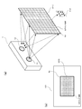
- FIG. 1 It is a figure which shows schematic structure of the object detection apparatus which concerns on embodiment. It is a figure which shows the structure of the information acquisition apparatus and information processing apparatus which concern on embodiment. It is the figure which shows typically the irradiation state of the laser beam with respect to the target area
- an information acquisition device of a type that irradiates a target area with laser light having a predetermined dot pattern is exemplified.
- FIG. 1 shows a schematic configuration of the object detection apparatus according to the present embodiment.
- the object detection device includes an information acquisition device 1 and an information processing device 2.
- the television 3 is controlled by a signal from the information processing device 2.
- a device including the information acquisition device 1 and the information processing device 2 corresponds to the object detection device of the present invention.
- the information acquisition device 1 projects infrared light over the entire target area and receives the reflected light with a CMOS image sensor, whereby the distance between each part of the object in the target area (hereinafter referred to as “three-dimensional distance information”). To get.
- the acquired three-dimensional distance information is sent to the information processing apparatus 2 via the cable 4.
- the information processing apparatus 2 is, for example, a controller for TV control, a game machine, a personal computer, or the like.
- the information processing device 2 detects an object in the target area based on the three-dimensional distance information received from the information acquisition device 1, and controls the television 3 based on the detection result.
- the information processing apparatus 2 detects a person based on the received three-dimensional distance information and detects the movement of the person from the change in the three-dimensional distance information.
- the information processing device 2 is a television control controller
- the information processing device 2 detects the person's gesture from the received three-dimensional distance information and outputs a control signal to the television 3 in accordance with the gesture.
- the application program to be installed is installed.
- the user can cause the television 3 to execute a predetermined function such as channel switching or volume up / down by making a predetermined gesture while watching the television 3.
- the information processing device 2 when the information processing device 2 is a game machine, the information processing device 2 detects the person's movement from the received three-dimensional distance information, and displays a character on the television screen according to the detected movement.
- An application program that operates and changes the game battle situation is installed. In this case, the user can experience a sense of realism in which he / she plays a game as a character on the television screen by making a predetermined movement while watching the television 3.
- FIG. 2 is a diagram showing the configuration of the information acquisition device 1 and the information processing device 2.
- the information acquisition apparatus 1 includes a projection optical system 11 and a light receiving optical system 12 as a configuration of the optical unit.
- the information acquisition device 1 includes a CPU (Central Processing Unit) 21, a laser driving circuit 22, an imaging signal processing circuit 23, an input / output circuit 24, and a memory 25 as a circuit unit.
- CPU Central Processing Unit
- the projection optical system 11 irradiates a target area with laser light having a predetermined dot pattern.
- the light receiving optical system 12 receives the laser beam reflected from the target area.
- the configurations of the projection optical system 11 and the light receiving optical system 12 will be described later with reference to FIGS.
- the CPU 21 controls each unit according to a control program stored in the memory 25.
- the CPU 21 has functions of a laser control unit 21 a for controlling a laser light source 111 (described later) in the projection optical system 11 and a three-dimensional distance calculation unit 21 b for generating three-dimensional distance information. Is granted.
- the laser drive circuit 22 drives a laser light source 111 (described later) according to a control signal from the CPU 21.
- the imaging signal processing circuit 23 controls a CMOS image sensor 123 (described later) in the light receiving optical system 12 and sequentially takes in each pixel signal (charge) generated by the CMOS image sensor 123 for each line. Then, the captured signals are sequentially output to the CPU 21.
- CPU21 calculates the distance from the information acquisition apparatus 1 to each part of a detection target based on the signal (imaging signal) supplied from the imaging signal processing circuit 23 by the process by the three-dimensional distance calculation part 21b.
- the input / output circuit 24 controls data communication with the information processing apparatus 2.
- the information processing apparatus 2 includes a CPU 31, an input / output circuit 32, and a memory 33.
- the information processing apparatus 2 has a configuration for performing communication with the television 3 and for reading information stored in an external memory such as a CD-ROM and installing it in the memory 33.
- an external memory such as a CD-ROM
- the configuration of these peripheral circuits is not shown for the sake of convenience.
- the CPU 31 controls each unit according to a control program (application program) stored in the memory 33.
- a control program application program
- the CPU 31 is provided with the function of the object detection unit 31a for detecting an object in the image.
- a control program is read from a CD-ROM by a drive device (not shown) and installed in the memory 33, for example.
- the object detection unit 31a detects a person in the image and its movement from the three-dimensional distance information supplied from the information acquisition device 1. Then, a process for operating the character on the television screen according to the detected movement is executed by the control program.
- the object detection unit 31 a detects a person in the image and its movement (gesture) from the three-dimensional distance information supplied from the information acquisition device 1. To do. Then, processing for controlling functions (channel switching, volume adjustment, etc.) of the television 3 is executed by the control program in accordance with the detected movement (gesture).
- the input / output circuit 32 controls data communication with the information acquisition device 1.
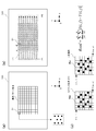
- FIG. 3 (a) is a diagram schematically showing the irradiation state of the laser light on the target area
- FIG. 3 (b) is a diagram schematically showing the light receiving state of the laser light in the CMOS image sensor 123.
- FIG. 6B shows a light receiving state when a flat surface (screen) exists in the target area.
- the projection optical system 11 emits laser light having a dot pattern (hereinafter, the entire laser light having this pattern is referred to as “DP light”) toward the target region. Is done.
- the DP light projection area is indicated by a solid frame.
- dot regions hereinafter simply referred to as “dots” in which the intensity of the laser light is increased by the diffractive action of the diffractive optical element are scattered according to the dot pattern by the diffractive action of the diffractive optical element. Yes.
- the light beam of DP light is divided into a plurality of segment regions arranged in a matrix.
- dots are scattered in a unique pattern.
- the dot dot pattern in one segment area is different from the dot dot pattern in all other segment areas.
- each segment area can be distinguished from all other segment areas with a dot dot pattern.
- the segment areas of DP light reflected thereby are distributed in a matrix on the CMOS image sensor 123 as shown in FIG.
- the light in the segment area S0 on the target area shown in FIG. 9A enters the segment area Sp shown in FIG.
- the light flux region of DP light is indicated by a solid frame, and for convenience, the light beam of DP light is divided into a plurality of segment regions arranged in a matrix.
- the three-dimensional distance calculation unit 21b detects at which position on the CMOS image sensor 123 each segment region is incident (hereinafter referred to as “pattern matching”), and based on the light receiving position based on the triangulation method. Thus, the distance to each part (irradiation position of each segment area) of the detection target object is detected. Details of such a detection technique are described in, for example, Non-Patent Document 1 (The 19th Annual Conference of the Robotics Society of Japan (September 18-20, 2001), Proceedings, P1279-1280).
- FIG. 4 is a diagram schematically showing a method of generating a reference template used for the distance detection.
- a flat reflection plane RS perpendicular to the Z-axis direction is arranged at a predetermined distance Ls from the projection optical system 11.
- the temperature of the laser light source 111 is maintained at a predetermined temperature (reference temperature).
- DP light is emitted from the projection optical system 11 for a predetermined time Te.
- the emitted DP light is reflected by the reflection plane RS and enters the CMOS image sensor 123 of the light receiving optical system 12.
- an electrical signal for each pixel is output from the CMOS image sensor 123.
- the output electric signal value (pixel value) for each pixel is developed on the memory 25 of FIG.
- each segment area is dotted with dots in a unique pattern. Therefore, the pixel value pattern of the segment area is different for each segment area.
- each segment area has the same size as all other segment areas.
- the reference template is configured by associating each segment area set on the CMOS image sensor 123 with the pixel value of each pixel included in the segment area.
- the reference template includes information on the position of the reference pattern area on the CMOS image sensor 123, pixel values of all pixels included in the reference pattern area, and information for dividing the reference pattern area into segment areas. Contains.
- the pixel values of all the pixels included in the reference pattern area correspond to the DP light dot pattern included in the reference pattern area.
- the mapping area of the pixel values of all the pixels included in the reference pattern area into segment areas the pixel values of the pixels included in each segment area are acquired.
- the reference template may further hold pixel values of pixels included in each segment area for each segment area.
- the configured reference template is held in the memory 25 of FIG. 2 in an unerasable state.
- the reference template thus stored in the memory 25 is referred to when calculating the distance from the projection optical system 11 to each part of the detection target object.
- DP light corresponding to a predetermined segment area Sn on the reference pattern is reflected by the object, and the segment area Sn. It is incident on a different region Sn ′. Since the projection optical system 11 and the light receiving optical system 12 are adjacent to each other in the X-axis direction, the displacement direction of the region Sn ′ with respect to the segment region Sn is parallel to the X-axis. In the case of FIG. 4A, since the object is located at a position closer than the distance Ls, the region Sn 'is displaced in the X-axis positive direction with respect to the segment region Sn. If the object is at a position farther than the distance Ls, the region Sn ′ is displaced in the negative X-axis direction with respect to the segment region Sn.
- the distance Lr from the projection optical system 11 to the portion of the object irradiated with DP light (DPn) is triangulated using the distance Ls. Calculated based on Similarly, the distance from the projection optical system 11 is calculated for the part of the object corresponding to another segment area.
- FIG. 5 is a diagram for explaining such a detection technique.
- FIG. 5A is a diagram showing the setting state of the reference pattern region and the segment region on the CMOS image sensor 123
- FIG. 5B is a diagram showing a method for searching the segment region at the time of actual measurement
- FIG. These are figures which show the collation method with the dot pattern of measured DP light, and the dot pattern contained in the segment area
- the segment area S1 is one pixel in the X-axis direction in the range P1 to P2.
- the matching degree between the dot pattern of the segment area S1 and the actually measured dot pattern of DP light is obtained.
- the segment area S1 is sent in the X-axis direction only on the line L1 passing through the uppermost segment area group of the reference pattern area. This is because, as described above, each segment region is normally displaced only in the X-axis direction from the position set by the reference template at the time of actual measurement. That is, the segment area S1 is considered to be on the uppermost line L1.
- the processing load for the search is reduced.
- the segment area may protrude from the reference pattern area in the X-axis direction. Therefore, the ranges P1 and P2 are set wider than the width of the reference pattern area in the X-axis direction.
- a region (comparison region) having the same size as the segment region S1 is set on the line L1, and the similarity between the comparison region and the segment region S1 is obtained. That is, the difference between the pixel value of each pixel in the segment area S1 and the pixel value of the corresponding pixel in the comparison area is obtained. A value Rsad obtained by adding the obtained difference to all the pixels in the comparison region is acquired as a value indicating the similarity.
- the comparison area is sequentially set while being shifted by one pixel on the line L1. Then, the value Rsad is obtained for all the comparison regions on the line L1. A value smaller than the threshold value is extracted from the obtained value Rsad. If there is no value Rsad smaller than the threshold value, the search for the segment area S1 is regarded as an error. Then, it is determined that the comparison area corresponding to the extracted Rsad having the smallest value is the movement area of the segment area S1. The same search as described above is performed for the segment areas other than the segment area S1 on the line L1. Similarly, the segment areas on the other lines are searched by setting the comparison area on the lines as described above.
- FIG. 6 is a perspective view showing an installation state of the projection optical system 11 and the light receiving optical system 12.
- the projection optical system 11 and the light receiving optical system 12 are installed on a base plate 300 having high thermal conductivity.
- the optical members constituting the projection optical system 11 are installed on the chassis 11 a, and the chassis 11 a is installed on the base plate 300. Thereby, the projection optical system 11 is installed on the base plate 300.
- the light receiving optical system 12 is installed on the upper surface of the two pedestals 300a on the base plate 300 and the upper surface of the base plate 300 between the two pedestals 300a.
- a CMOS image sensor 123 described later is installed on the upper surface of the base plate 300 between the two pedestals 300a, and a holding plate 12a is installed on the upper surface of the pedestal 300a.
- a lens holder 12b for holding 122 is installed.
- the projection optical system 11 and the light receiving optical system 12 are installed side by side with a predetermined distance in the X axis direction so that the projection center of the projection optical system 11 and the imaging center of the light receiving optical system 12 are aligned on a straight line parallel to the X axis.
- a circuit board 200 (see FIG. 7) that holds the circuit unit (see FIG. 2) of the information acquisition device 1 is installed on the back surface of the base plate 300.
- a hole 300 b for taking out the wiring of the laser light source 111 to the back of the base plate 300 is formed in the lower center of the base plate 300.
- an opening 300 c for exposing the connector 12 c of the CMOS image sensor 123 to the back of the base plate 300 is formed below the installation position of the light receiving optical system 12 on the base plate 300.
- FIG. 7 is a diagram schematically showing the configuration of the projection optical system 11 and the light receiving optical system 12 according to the present embodiment.
- the projection optical system 11 includes a laser light source 111, a collimator lens 112, a rising mirror 113, and a diffractive optical element (DOE: Diffractive Optical Element) 114.
- the light receiving optical system 12 includes a filter 121, an imaging lens 122, and a CMOS image sensor 123.
- the laser light source 111 outputs laser light in a narrow wavelength band with a wavelength of about 830 nm.
- the laser light source 111 is installed so that the optical axis of the laser light is parallel to the X axis.
- the collimator lens 112 converts the laser light emitted from the laser light source 111 into substantially parallel light.
- the collimator lens 112 is installed so that its own optical axis is aligned with the optical axis of the laser light emitted from the laser light source 111.
- the raising mirror 113 reflects the laser beam incident from the collimator lens 112 side.
- the optical axis of the laser beam is bent 90 ° by the rising mirror 113 and becomes parallel to the Z axis.
- the DOE 114 has a diffraction pattern on the incident surface.
- the DOE 114 is formed by injection molding using a resin or using a lithography and dry etching technique on a glass substrate.
- the diffraction pattern is composed of, for example, a step type hologram. Due to the diffractive action of this diffraction pattern, the laser light reflected by the rising mirror 113 and incident on the DOE 114 is converted into a laser light having a dot pattern and irradiated onto the target area.
- the diffraction pattern is designed to be a predetermined dot pattern in the target area. The dot pattern in the target area will be described later with reference to FIGS.
- an aperture (not shown) for making the contour of the laser light circular is arranged between the laser light source 111 and the collimator lens 112. Note that this aperture may be constituted by an emission opening of the laser light source 111.
- the laser light reflected from the target area passes through the filter 121 and enters the imaging lens 122.
- the filter 121 transmits light in a wavelength band including the emission wavelength (about 830 nm) of the laser light source 111 and cuts other wavelength bands.
- the imaging lens 122 condenses the light incident through the filter 121 on the CMOS image sensor 123.
- the imaging lens 122 includes a plurality of lenses, and an aperture and a spacer are interposed between the predetermined lenses. Such an aperture stops the light from the outside so as to match the F number of the imaging lens 122.
- the CMOS image sensor 123 receives the light collected by the imaging lens 122 and outputs a signal (charge) corresponding to the amount of received light to the imaging signal processing circuit 23 for each pixel.
- the output speed of the signal is increased so that the signal (charge) of the pixel can be output to the imaging signal processing circuit 23 with high response from the light reception in each pixel.
- the filter 121 is arranged so that the light receiving surface is perpendicular to the Z axis.
- the imaging lens 122 is installed so that the optical axis is parallel to the Z axis.
- the CMOS image sensor 123 is installed such that the light receiving surface is perpendicular to the Z axis.
- the filter 121, the imaging lens 122, and the CMOS image sensor 123 are arranged so that the center of the filter 121 and the center of the light receiving region of the CMOS image sensor 123 are aligned on the optical axis of the imaging lens 122.
- the projection optical system 11 and the light receiving optical system 12 are installed on the base plate 300 as described with reference to FIG.
- a circuit board 200 is further installed on the lower surface of the base plate 300, and wirings (flexible boards) 201 and 202 are connected from the circuit board 200 to the laser light source 111 and the CMOS image sensor 123.
- the circuit unit of the information acquisition apparatus 1 such as the CPU 21 and the laser driving circuit 22 shown in FIG.
- the DOE 114 is normally designed so that the dots of the dot pattern are uniformly distributed with the same brightness in the target area. By dispersing the dots in this way, it is possible to search the target area evenly.
- the dot pattern is actually generated using the DOE 114 designed in this way, the brightness of the dot differs depending on the region. Moreover, it turned out that there exists a fixed tendency in the difference in the brightness
- analysis and evaluation of DOE 114 performed by the inventors of the present application will be described.
- the inventor of the present application adjusted the diffraction pattern of the DOE 114 as a comparative example so that the dots of the dot pattern are uniformly distributed with the same luminance on the target area. Subsequently, the inventor of the present application actually projected the dot pattern onto the target area using the DOE 114 configured according to such a design, and captured the projected state of the dot pattern at that time with the CMOS image sensor 123. Then, the brightness distribution of the dot pattern on the CMOS image sensor 123 was measured from the received light amount (detection signal) of each pixel of the CMOS image sensor 123.
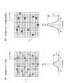
- FIG. 8A shows measurement results showing the luminance distribution on the CMOS image sensor 123 when the DOE 114 of the comparative example is used.
- the central portion of FIG. 8A shows the luminance distribution on the light receiving surface (two-dimensional plane) of the CMOS image sensor 123 by color (in this figure, the luminance difference is represented by the color difference).
- FIG. 8A On the left side and the lower side of FIG. 8A, the luminance values of the portions along the A-A ′ line and the B-B ′ line of the luminance distribution diagram are respectively shown by graphs.
- FIG. 8 (b) is a diagram schematically showing the luminance distribution of FIG. 8 (a).
- the luminance level on the CMOS image sensor 123 is displayed in nine stages, and it can be seen that the luminance decreases from the central part toward the peripheral part.
- the luminance on the CMOS image sensor 123 is maximum at the center and decreases as the distance from the center increases.
- the luminance variation actually occurs on the CMOS image sensor 123. That is, it can be seen from this measurement result that the dot pattern projected onto the target area has a lower dot brightness as it goes from the center to the periphery.
- the luminance of the dots changes radially from the center. That is, it is considered that the dots having substantially the same brightness are distributed in a substantially concentric shape with respect to the center of the dot pattern, and the brightness of the dots gradually decreases with increasing distance from the center.
- the inventors of the present application performed the same measurement as described above for a plurality of DOEs 114 formed in the same manner, this tendency was confirmed in any of the DOEs 114. Therefore, when the DOE 114 is designed so that the dots of the dot pattern are uniformly distributed with the same brightness on the target area, the dots projected on the target area are generally distributed with the above-described tendency. Conceivable.
- the gain of the detection signal in the peripheral portion of the CMOS image sensor 123 can be set large.
- the detection signal based on the stray light also becomes large, and it becomes difficult to properly detect the peripheral dots with low luminance.
- the diffraction pattern of the DOE 114 is adjusted so that the dot pattern is unevenly distributed in the target area.
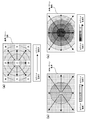
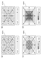
- FIG. 9A is a diagram schematically showing the distribution state of dots in the target area of the present embodiment.
- the DOE 114 according to the present embodiment is configured so that the density of dots in the target area decreases concentrically from the center (in proportion to the distance from the center) by the diffraction action as shown in the figure.
- a portion indicated by a broken line in the figure is a region where the density of dots is substantially equal.
- the dot density may be decreased linearly with increasing distance from the center of the dot pattern, or may be decreased stepwise.
- the dot density is decreased stepwise, as shown in FIGS. 9B and 9C, a plurality of areas are set concentrically from the center of the dot pattern, and the dot density is within each area. Are equal.
- regions having the same dot density are shown with the same darkness.
- the density of dots is reduced by, for example, combining a plurality of dots into one.
- the comparative example it is assumed that 22 dots are included in one segment area (15 pixels ⁇ 15 pixels).
- the brightness of each dot has the brightness B1 schematically shown on the lower side of FIG. From this state, for example, as indicated by a dotted arrow, the design of the DOE 114 is adjusted so that 11 dots are led to positions where they overlap each other 11 dots, respectively.
- FIG. 11B 11 dots are included in one segment area, and the dot density is halved compared to the comparative example. At this time, since each dot in FIG.
- the brightness B2 is about twice as high.
- the brightness is increased while the dot density is reduced.
- the dot superposition as described above is not performed at the center of the dot pattern. Accordingly, the density and brightness of the dot at the center of the dot pattern are the same as in the comparative example.
- the dots in the same segment area are overlapped, but actually, a plurality of dots are overlapped so that the pattern of the dots included in each segment area is a unique pattern, Dot density is reduced. Dots that overlap each other need not be included in the same segment area. In this way, the diffraction pattern of the DOE 114 is adjusted so that the dot pattern of each segment area becomes a unique pattern and the density of dots around the dot pattern is reduced.
- the density of the dots in the peripheral portion is reduced, the luminance in the peripheral portion is increased as described above, so that the dots in the peripheral portion are not easily buried in stray light.
- the number of dots included in the peripheral segment area is smaller than the number of dots included in the central segment area, the pattern matching accuracy of the peripheral segment area may be reduced. is there.
- the diffraction pattern of the DOE 114 is adjusted as shown in FIG. 9A, and the peripheral segment area is set larger than the central segment area.
- FIGS. 11 (a) and 11 (b) are diagrams showing the segment areas in the central part and the peripheral part in the present embodiment, respectively. Also in this embodiment, as in the case of FIGS. 10A and 10B, the density of the dots in the peripheral portion is assumed to be 1 ⁇ 2 of the density of the dots in the central portion.
- the central segment area is set to 15 pixels ⁇ 15 pixels, and one segment area has 22 Contains dots.
- the peripheral segment area is set to 21 pixels ⁇ 21 pixels. Since the density of the peripheral portion is 1 ⁇ 2 of the density of the central portion, here, the area of the peripheral segment region is set so that the area of the peripheral segment region is about twice that of the central segment region. One side is set to 21 pixels, for example. In this case, the number of pixels included in the peripheral segment area is approximately twice the number of pixels included in the central segment area. Accordingly, the number of dots (22) included in the peripheral segment area is equal to the number of dots (22) included in the central segment area.
- the size of the segment area is appropriately set according to the difference in dot density from the center.
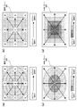
- the segment when the density decreases linearly according to the distance from the central portion, as shown in FIG. 12A, the segment depends on the density of dots on the reference pattern area.
- the size of the area is set to change.
- FIGS. 9B and 9C when the density gradually decreases according to the distance from the center, as shown in FIGS. 12B and 12C, respectively, In accordance with the density of dots on the pattern area, the size of the segment area is set to change stepwise.
- information on the position of the reference pattern area on the CMOS image sensor 123, pixel values of all pixels included in the reference pattern area, information on the vertical and horizontal widths of the segment area, and information on the position of the segment area Is the reference template.
- the reference template of the present embodiment is also held in the memory 25 of FIG.
- the reference template thus stored in the memory 25 is referred to by the CPU 21 when calculating the distance from the projection optical system 11 to each part of the detection target object.
- FIG. 13A is a flowchart showing a dot pattern setting process for a segment area. Such processing is performed when the information acquisition apparatus 1 is activated or when distance detection is started.
- the reference template includes information for assigning individual segment areas whose sizes are adjusted as described above to the reference pattern area (see FIG. 4B). Specifically, the reference template includes information indicating the position of each segment area on the reference pattern area and information indicating the size (vertical and horizontal width) of each segment area.
- N segment areas whose sizes are adjusted with respect to the reference pattern area are allocated, and serial numbers from 1 to N are assigned to these segment areas.
- the CPU 21 of the information acquisition apparatus 1 reads out information on the position of the reference pattern area on the CMOS image sensor 123 and the pixel values of all the pixels included in the reference pattern area from the reference template held in the memory 25 ( S11). Subsequently, the CPU 21 sets 1 to the variable k (S12).
- the CPU 21 acquires information on the vertical and horizontal widths of the k-th segment area Sk and information on the position of the segment area Sk from the reference template stored in the memory 25 (S13). Subsequently, the CPU 21 sets the dot pattern Dk used for the search from the pixel values of all the pixels included in the reference pattern area and the information on the segment area Sk acquired in S13 (S14). Specifically, the CPU 21 acquires the pixel value of the dot pattern included in the segment area Sk among the pixel values of all the pixels of the reference pattern, and sets this as the search dot pattern Dk.
- the CPU 21 determines whether the value of k is equal to N (S15).
- the dot pattern used for the search is set for all the segment areas and the value of k becomes N (S15: YES)
- the process ends.
- the CPU 21 increases the value of k by 1 (S16), and returns the process to S13. In this way, N dot patterns used for the search are sequentially set.
- FIG. 13B is a flowchart showing distance detection processing at the time of actual measurement. This process is performed using the search dot pattern set by the process of FIG. 13A, and is performed in parallel with the process of FIG.
- the CPU 21 of the information acquisition device 1 first sets 1 to the variable c (S21). Next, the CPU 21 searches the dot pattern on the CMOS image sensor 123 received at the time of actual measurement for an area that matches the c-th search dot pattern Dc set in S14 of FIG. 13A (S22). Such a search is performed on an area having a predetermined width in the left-right direction with respect to a position corresponding to the segment area Sc. If there is an area that matches the search dot pattern Dc, the CPU 21 detects how far the matched area has moved in the left or right direction from the position of the segment area Sc, and the detected movement direction and movement. Using the distance, the distance of the object located in the segment area Sc is calculated based on the triangulation method (S23).
- the CPU 21 determines whether the value of c is equal to N (S24). The distance is calculated for all the segment areas, and when the value of c becomes N (S24: YES), the process ends. On the other hand, if the value of c has not reached N (S24: NO), the CPU 21 increases the value of c by 1 (S25), and returns the process to S22. Thus, the distance to the detection target object corresponding to the segment area is obtained.
- the density of the peripheral portion of the dot pattern is set smaller than the density of the central portion.
- the brightness per dot in the peripheral portion is increased, and each dot is less likely to be buried in stray light, making it easier to grasp the position of the dot.
- the peripheral segment region is set larger than the central segment region as shown in FIGS. Is done.
- the CMOS image sensor 123 is used as the photodetector, but a CCD image sensor may be used instead.
- the laser light source 111 and the collimator lens 112 are arranged in the X-axis direction, and the optical axis of the laser beam is bent in the Z-axis direction by the rising mirror 113.
- the laser light source 111 may be arranged so as to emit, and the laser light source 111, the collimator lens 112, and the DOE 114 may be arranged side by side in the Z-axis direction.
- the rising mirror 113 can be omitted, but the dimension of the projection optical system 11 increases in the Z-axis direction.
- the diffraction pattern of the DOE 114 is set so that the density of the dots in the periphery of the dot pattern is 1 ⁇ 2 of the density of the dots in the center. Has been adjusted.
- the present invention is not limited to this, and the density of the dots in the periphery of the dot pattern may be set so that the brightness in the periphery is increased.
- the number of pixels in one segment area is also set to 15 pixels ⁇ 15 pixels in the central portion and 21 pixels ⁇ 21 pixels in the peripheral portion as shown in FIGS. It was done.
- the present invention is not limited to this, and the number of pixels included in the peripheral segment region may be set to another pixel number so as to be larger than the number of pixels included in the central segment region.
- the density of dots in the target area is configured to decrease concentrically as the distance from the center increases.
- an elliptical shape and a rectangular shape may be configured so as to become linearly smaller as the distance from the center increases.
- the density of the dots may be configured to decrease stepwise as they move away radially from the center of the dot pattern.
- the segment area is set by dividing the reference pattern area into a matrix, but the segment area may be set so that the segment areas adjacent to each other on the left and right overlap each other.
- the segment areas may be set so that the segment areas adjacent in the vertical direction overlap each other.
- each segment region is set so that the peripheral portion is larger than the central portion of the dot pattern as described above.
Landscapes
- Physics & Mathematics (AREA)
- Engineering & Computer Science (AREA)
- General Physics & Mathematics (AREA)
- Electromagnetism (AREA)
- Computer Vision & Pattern Recognition (AREA)
- Radar, Positioning & Navigation (AREA)
- Remote Sensing (AREA)
- Computer Networks & Wireless Communication (AREA)
- Measurement Of Optical Distance (AREA)
- Length Measuring Devices By Optical Means (AREA)
Abstract
Description
本発明は、目標領域に光を投射したときの反射光の状態に基づいて目標領域内の物体を検出する物体検出装置、および、当該物体検出装置に用いて好適な情報取得装置に関する。 The present invention relates to an object detection apparatus that detects an object in a target area based on a state of reflected light when light is projected onto the target area, and an information acquisition apparatus suitable for use in the object detection apparatus.
従来、光を用いた物体検出装置が種々の分野で開発されている。いわゆる距離画像センサを用いた物体検出装置では、2次元平面上の平面的な画像のみならず、検出対象物体の奥行き方向の形状や動きを検出することができる。かかる物体検出装置では、レーザ光源やLED(Light Emitting Diode)から、予め決められた波長帯域の光が目標領域に投射され、その反射光がCMOSイメージセンサ等の光検出器により受光(撮像)される。距離画像センサとして、種々のタイプのものが知られている。 Conventionally, an object detection device using light has been developed in various fields. An object detection apparatus using a so-called distance image sensor can detect not only a planar image on a two-dimensional plane but also the shape and movement of the detection target object in the depth direction. In such an object detection device, light in a predetermined wavelength band is projected from a laser light source or LED (Light Emitting Diode) onto a target area, and the reflected light is received (imaged) by a photodetector such as a CMOS image sensor. The Various types of distance image sensors are known.
所定のドットパターンを持つレーザ光を目標領域に照射するタイプの距離画像センサでは、ドットパターンを持つレーザ光の目標領域からの反射光が光検出器によって受光される。そして、ドットの光検出器上の受光位置に基づいて、三角測量法を用いて、検出対象物体の各部(検出対象物体上の各ドットの照射位置)までの距離が検出される(たとえば、非特許文献1)。 In a distance image sensor of a type that irradiates a target area with laser light having a predetermined dot pattern, reflected light from the target area of laser light having a dot pattern is received by a photodetector. Then, based on the light receiving position of the dot on the photodetector, the distance to each part of the detection target object (irradiation position of each dot on the detection target object) is detected using a triangulation method (for example, non- Patent Document 1).
上記物体検出装置では、レーザ光源から出射されたレーザ光を回折光学素子により回折させて、ドットパターンを持つレーザ光が生成される。この場合、回折光学素子は、たとえば、目標領域上のドットパターンが同じ輝度で均一に分布するよう設計される。しかしながら、回折光学素子に生じる成形誤差等により、目標領域において、周辺部のドットの輝度が、中心部のドットの輝度に比べて小さくなることがある。この場合、周辺部のドットの密度を低下させて周辺部のドットの輝度を高めるようにするのが望ましい。しかし、こうすると、周辺部における距離検出の精度が低下する惧れがある。 In the object detection apparatus, laser light having a dot pattern is generated by diffracting laser light emitted from a laser light source by a diffractive optical element. In this case, the diffractive optical element is designed, for example, so that the dot pattern on the target area is uniformly distributed with the same luminance. However, the brightness of the dots in the peripheral portion may be smaller than the brightness of the dots in the central portion in the target area due to a molding error or the like generated in the diffractive optical element. In this case, it is desirable to increase the brightness of the dots in the peripheral portion by reducing the density of the dots in the peripheral portion. However, this may reduce the accuracy of distance detection in the peripheral portion.
本発明は、このような課題を解消するためになされたものであり、ドットパターンの周辺部における距離検出の精度の低下を抑制することができる情報取得装置および物体検出装置を提供することを目的とする。 The present invention has been made to solve such a problem, and an object of the present invention is to provide an information acquisition device and an object detection device that can suppress a decrease in the accuracy of distance detection in the periphery of a dot pattern. And
本発明の第1の態様は、光を用いて目標領域の情報を取得する情報取得装置に関する。本態様に係る情報取得装置は、前記目標領域に所定のドットパターンでレーザ光を投射する投射光学系と、前記投射光学系に対して所定の距離だけ離れて並ぶように配置され、前記目標領域を撮像する受光光学系と、前記受光光学系により撮像された前記ドットパターンに基づいて目標領域に存在する物体の各部までの距離を取得する距離取得部と、を備える。ここで、前記投射光学系は、前記目標領域における前記ドットパターンのドットの密度が、前記ドットパターンの中心部よりも周辺部の方が小さくなるよう構成される。前記距離取得部は、基準面により反射され前記受光光学系により撮像された基準ドットパターンをセグメント領域に区分し、距離測定時に目標領域を撮像して取得された撮像ドットパターンと前記各セグメント領域内のドットとを照合することにより、前記各セグメント領域についての距離を取得する。前記セグメント領域は、前記基準ドットパターンの中心部よりも周辺部の方が大きくなるよう設定される。 1st aspect of this invention is related with the information acquisition apparatus which acquires the information of a target area | region using light. The information acquisition apparatus according to this aspect is arranged so as to be aligned with a projection optical system that projects a laser beam with a predetermined dot pattern on the target area, a predetermined distance away from the projection optical system, and the target area And a distance acquisition unit that acquires the distance to each part of the object existing in the target area based on the dot pattern imaged by the light receiving optical system. Here, the projection optical system is configured such that the dot density of the dot pattern in the target region is smaller in the peripheral portion than in the central portion of the dot pattern. The distance acquisition unit divides a reference dot pattern reflected by a reference surface and imaged by the light receiving optical system into segment areas, and captures the target area at the time of distance measurement and acquires the captured dot pattern and each segment area The distance for each segment area is obtained by collating with the dots. The segment area is set so that the peripheral area is larger than the central area of the reference dot pattern.
本発明の第2の態様は、物体検出装置に関する。本態様に係る物体検出装置は、上記第1の態様に係る情報取得装置を有する。 The second aspect of the present invention relates to an object detection apparatus. The object detection apparatus according to this aspect includes the information acquisition apparatus according to the first aspect.
本発明によれば、ドットパターンの周辺部における距離検出の精度の低下を抑制することができる情報取得装置および物体検出装置を提供することができる。 According to the present invention, it is possible to provide an information acquisition device and an object detection device that can suppress a decrease in accuracy of distance detection in the peripheral portion of a dot pattern.
本発明の特徴は、以下に示す実施の形態の説明により更に明らかとなろう。ただし、以下の実施の形態は、あくまでも、本発明の一つの実施形態であって、本発明ないし各構成要件の用語の意義は、以下の実施の形態に記載されたものに制限されるものではない。 The characteristics of the present invention will be further clarified by the description of the embodiments shown below. However, the following embodiment is merely one embodiment of the present invention, and the meaning of the term of the present invention or each constituent element is not limited to that described in the following embodiment. Absent.
以下、本発明の実施の形態につき図面を参照して説明する。本実施の形態には、所定のドットパターンを持つレーザ光を目標領域に照射するタイプの情報取得装置が例示されている。 Hereinafter, embodiments of the present invention will be described with reference to the drawings. In the present embodiment, an information acquisition device of a type that irradiates a target area with laser light having a predetermined dot pattern is exemplified.
まず、図1に本実施の形態に係る物体検出装置の概略構成を示す。図示の如く、物体検出装置は、情報取得装置1と、情報処理装置2とを備えている。テレビ3は、情報処理装置2からの信号によって制御される。なお、情報取得装置1と情報処理装置2とからなる装置が、本発明の物体検出装置に相当する。
First, FIG. 1 shows a schematic configuration of the object detection apparatus according to the present embodiment. As illustrated, the object detection device includes an
情報取得装置1は、目標領域全体に赤外光を投射し、その反射光をCMOSイメージセンサにて受光することにより、目標領域にある物体各部の距離(以下、「3次元距離情報」という)を取得する。取得された3次元距離情報は、ケーブル4を介して情報処理装置2に送られる。
The
情報処理装置2は、たとえば、テレビ制御用のコントローラやゲーム機、パーソナルコンピュータ等である。情報処理装置2は、情報取得装置1から受信した3次元距離情報に基づき、目標領域における物体を検出し、検出結果に基づきテレビ3を制御する。
The
たとえば、情報処理装置2は、受信した3次元距離情報に基づき人を検出するとともに、3次元距離情報の変化から、その人の動きを検出する。たとえば、情報処理装置2がテレビ制御用のコントローラである場合、情報処理装置2には、受信した3次元距離情報からその人のジェスチャを検出するとともに、ジェスチャに応じてテレビ3に制御信号を出力するアプリケーションプログラムがインストールされている。この場合、ユーザは、テレビ3を見ながら所定のジェスチャをすることにより、チャンネル切り替えやボリュームのUp/Down等、所定の機能をテレビ3に実行させることができる。
For example, the
また、たとえば、情報処理装置2がゲーム機である場合、情報処理装置2には、受信した3次元距離情報からその人の動きを検出するとともに、検出した動きに応じてテレビ画面上のキャラクタを動作させ、ゲームの対戦状況を変化させるアプリケーションプログラムがインストールされている。この場合、ユーザは、テレビ3を見ながら所定の動きをすることにより、自身がテレビ画面上のキャラクタとしてゲームの対戦を行う臨場感を味わうことができる。
Further, for example, when the
図2は、情報取得装置1と情報処理装置2の構成を示す図である。
FIG. 2 is a diagram showing the configuration of the
情報取得装置1は、光学部の構成として、投射光学系11と受光光学系12とを備えている。この他、情報取得装置1は、回路部の構成として、CPU(Central Processing Unit)21と、レーザ駆動回路22と、撮像信号処理回路23と、入出力回路24と、メモリ25を備えている。
The
投射光学系11は、所定のドットパターンのレーザ光を、目標領域に照射する。受光光学系12は、目標領域から反射されたレーザ光を受光する。投射光学系11と受光光学系12の構成は、追って、図6、7を参照して説明する。
The projection
CPU21は、メモリ25に格納された制御プログラムに従って各部を制御する。かかる制御プログラムによって、CPU21には、投射光学系11内のレーザ光源111(後述)を制御するためのレーザ制御部21aと、3次元距離情報を生成するための3次元距離演算部21bの機能が付与される。
The
レーザ駆動回路22は、CPU21からの制御信号に応じてレーザ光源111(後述)を駆動する。撮像信号処理回路23は、受光光学系12内のCMOSイメージセンサ123(後述)を制御して、CMOSイメージセンサ123で生成された各画素の信号(電荷)をライン毎に順次取り込む。そして、取り込んだ信号を順次CPU21に出力する。
The
CPU21は、撮像信号処理回路23から供給される信号(撮像信号)をもとに、情報取得装置1から検出対象物の各部までの距離を、3次元距離演算部21bによる処理によって算出する。入出力回路24は、情報処理装置2とのデータ通信を制御する。
CPU21 calculates the distance from the
情報処理装置2は、CPU31と、入出力回路32と、メモリ33を備えている。なお、情報処理装置2には、同図に示す構成の他、テレビ3との通信を行うための構成や、CD-ROM等の外部メモリに格納された情報を読み取ってメモリ33にインストールするためのドライブ装置等が配されるが、便宜上、これら周辺回路の構成は図示省略されている。
The
CPU31は、メモリ33に格納された制御プログラム(アプリケーションプログラム)に従って各部を制御する。かかる制御プログラムによって、CPU31には、画像中の物体を検出するための物体検出部31aの機能が付与される。かかる制御プログラムは、たとえば、図示しないドライブ装置によってCD-ROMから読み取られ、メモリ33にインストールされる。
The
たとえば、制御プログラムがゲームプログラムである場合、物体検出部31aは、情報取得装置1から供給される3次元距離情報から画像中の人およびその動きを検出する。そして、検出された動きに応じてテレビ画面上のキャラクタを動作させるための処理が制御プログラムにより実行される。
For example, when the control program is a game program, the
また、制御プログラムがテレビ3の機能を制御するためのプログラムである場合、物体検出部31aは、情報取得装置1から供給される3次元距離情報から画像中の人およびその動き(ジェスチャ)を検出する。そして、検出された動き(ジェスチャ)に応じて、テレビ3の機能(チャンネル切り替えやボリューム調整、等)を制御するための処理が制御プログラムにより実行される。
When the control program is a program for controlling the function of the
入出力回路32は、情報取得装置1とのデータ通信を制御する。
The input /
図3(a)は、目標領域に対するレーザ光の照射状態を模式的に示す図であり、図3(b)は、CMOSイメージセンサ123におけるレーザ光の受光状態を模式的に示す図である。なお、同図(b)には、便宜上、目標領域に平坦な面(スクリーン)が存在するときの受光状態が示されている。
FIG. 3 (a) is a diagram schematically showing the irradiation state of the laser light on the target area, and FIG. 3 (b) is a diagram schematically showing the light receiving state of the laser light in the
同図(a)に示すように、投射光学系11からは、ドットパターンを持ったレーザ光(以下、このパターンを持つレーザ光の全体を「DP光」という)が、目標領域に向けて照射される。同図(a)には、DP光の投射領域が実線の枠によって示されている。DP光の光束中には、回折光学素子による回折作用によってレーザ光の強度が高められたドット領域(以下、単に「ドット」という)が、回折光学素子の回折作用によるドットパターンに従って点在している。
As shown in FIG. 5A, the projection
なお、図3(a)では、便宜上、DP光の光束が、マトリックス状に並ぶ複数のセグメント領域に区分されている。各セグメント領域には、ドットが固有のパターンで点在している。一つのセグメント領域におけるドットの点在パターンは、他の全てのセグメント領域におけるドットの点在パターンと相違する。これにより、各セグメント領域は、ドットの点在パターンをもって、他の全てのセグメント領域から区別可能となっている。 In FIG. 3A, for convenience, the light beam of DP light is divided into a plurality of segment regions arranged in a matrix. In each segment area, dots are scattered in a unique pattern. The dot dot pattern in one segment area is different from the dot dot pattern in all other segment areas. As a result, each segment area can be distinguished from all other segment areas with a dot dot pattern.
目標領域に平坦な面(スクリーン)が存在すると、これにより反射されたDP光の各セグメント領域は、同図(b)のように、CMOSイメージセンサ123上においてマトリックス状に分布する。たとえば、同図(a)に示す目標領域上におけるセグメント領域S0の光は、CMOSイメージセンサ123上では、同図(b)に示すセグメント領域Spに入射する。なお、図3(b)においても、DP光の光束領域が実線の枠によって示され、便宜上、DP光の光束が、マトリックス状に並ぶ複数のセグメント領域に区分されている。
If there is a flat surface (screen) in the target area, the segment areas of DP light reflected thereby are distributed in a matrix on the
上記3次元距離演算部21bでは、各セグメント領域がCMOSイメージセンサ123上のどの位置に入射したかの検出(以下、「パターンマッチング」という)が行われ、その受光位置から、三角測量法に基づいて、検出対象物体の各部(各セグメント領域の照射位置)までの距離が検出される。かかる検出手法の詳細は、たとえば、上記非特許文献1(第19回日本ロボット学会学術講演会(2001年9月18-20日)予稿集、P1279-1280)に示されている。
The three-dimensional
図4は、上記距離検出に用いられる基準テンプレートの生成方法を模式的に示す図である。 FIG. 4 is a diagram schematically showing a method of generating a reference template used for the distance detection.
図4(a)に示すように、基準テンプレートの生成時には、投射光学系11から所定の距離Lsの位置に、Z軸方向に垂直な平坦な反射平面RSが配置される。レーザ光源111の温度は、所定の温度(基準温度)に維持される。この状態で、投射光学系11からDP光が所定時間Teだけ出射される。出射されたDP光は、反射平面RSによって反射され、受光光学系12のCMOSイメージセンサ123に入射する。これにより、CMOSイメージセンサ123から、画素毎の電気信号が出力される。出力された画素毎の電気信号の値(画素値)が、図2のメモリ25上に展開される。
As shown in FIG. 4A, when the reference template is generated, a flat reflection plane RS perpendicular to the Z-axis direction is arranged at a predetermined distance Ls from the projection
こうしてメモリ25上に展開された画素値に基づいて、図4(b)に示すように、CMOSイメージセンサ123上におけるDP光の照射領域を規定する基準パターン領域が設定される。さらに、この基準パターン領域が、縦横に区分されてセグメント領域が設定される。上記のように、各セグメント領域には、固有のパターンでドットが点在する。よって、セグメント領域の画素値のパターンは、セグメント領域毎に異なっている。なお、図4(b)の例では、各セグメント領域は、他の全てのセグメント領域と同じサイズである。
Thus, based on the pixel values developed on the
基準テンプレートは、このようにCMOSイメージセンサ123上に設定された各セグメント領域に、そのセグメント領域に含まれる各画素の画素値を対応付けて構成される。
The reference template is configured by associating each segment area set on the
具体的には、基準テンプレートは、CMOSイメージセンサ123上における基準パターン領域の位置に関する情報と、基準パターン領域に含まれる全画素の画素値と、基準パターン領域をセグメント領域に分割するための情報を含んでいる。基準パターン領域に含まれる全画素の画素値は、基準パターン領域に含まれるDP光のドットパターンに相応するものになる。また、基準パターン領域に含まれる全画素の画素値のマッピング領域をセグメント領域に区分することで、各セグメント領域に含まれる画素の画素値が取得される。なお、基準テンプレートは、さらに、各セグメント領域に含まれる画素の画素値を、セグメント領域毎に保持していても良い。
Specifically, the reference template includes information on the position of the reference pattern area on the
構成された基準テンプレートは、図2のメモリ25に、消去不可能な状態で保持される。こうしてメモリ25に保持された基準テンプレートは、投射光学系11から検出対象物体の各部までの距離を算出する際に参照される。
The configured reference template is held in the
たとえば、図4(a)に示すように距離Lsよりも近い位置に物体がある場合、基準パターン上の所定のセグメント領域Snに対応するDP光(DPn)は、物体によって反射され、セグメント領域Snとは異なる領域Sn’に入射する。投射光学系11と受光光学系12はX軸方向に隣り合っているため、セグメント領域Snに対する領域Sn’の変位方向はX軸に平行となる。図4(a)の場合、物体が距離Lsよりも近い位置にあるため、領域Sn’は、セグメント領域Snに対してX軸正方向に変位する。物体が距離Lsよりも遠い位置にあれば、領域Sn’は、セグメント領域Snに対してX軸負方向に変位する。
For example, as shown in FIG. 4A, when an object is present at a position closer than the distance Ls, DP light (DPn) corresponding to a predetermined segment area Sn on the reference pattern is reflected by the object, and the segment area Sn. It is incident on a different region Sn ′. Since the projection
セグメント領域Snに対する領域Sn’の変位方向と変位量をもとに、投射光学系11からDP光(DPn)が照射された物体の部分までの距離Lrが、距離Lsを用いて、三角測量法に基づき算出される。同様にして、他のセグメント領域に対応する物体の部分について、投射光学系11からの距離が算出される。
Based on the displacement direction and displacement amount of the region Sn ′ with respect to the segment region Sn, the distance Lr from the projection
かかる距離算出では、基準テンプレートのセグメント領域Snが、実測時においてどの位置に変位したかを検出する必要がある。この検出は、実測時にCMOSイメージセンサ123上に照射されたDP光のドットパターンと、セグメント領域Snに含まれるドットパターンとを照合することによって行われる。
In this distance calculation, it is necessary to detect to which position the segment area Sn of the reference template is displaced during actual measurement. This detection is performed by collating the dot pattern of DP light irradiated on the
図5は、かかる検出の手法を説明する図である。同図(a)は、CMOSイメージセンサ123上における基準パターン領域とセグメント領域の設定状態を示す図、同図(b)は、実測時におけるセグメント領域の探索方法を示す図、同図(c)は、実測されたDP光のドットパターンと、基準テンプレートのセグメント領域に含まれるドットパターンとの照合方法を示す図である。
FIG. 5 is a diagram for explaining such a detection technique. FIG. 5A is a diagram showing the setting state of the reference pattern region and the segment region on the
たとえば、同図(a)のセグメント領域S1の実測時における変位位置を探索する場合、同図(b)に示すように、セグメント領域S1が、範囲P1~P2において、X軸方向に1画素ずつ送られ、各送り位置において、セグメント領域S1のドットパターンと、実測されたDP光のドットパターンのマッチング度合いが求められる。この場合、セグメント領域S1は、基準パターン領域の最上段のセグメント領域群を通るラインL1上のみをX軸方向に送られる。これは、上記のように、通常、各セグメント領域は、実測時において、基準テンプレートにより設定された位置からX軸方向にのみ変位するためである。すなわち、セグメント領域S1は、最上段のラインL1上にあると考えられるためである。このように、X軸方向にのみ探索を行うことで、探索のための処理負担が軽減される。 For example, when searching for the displacement position at the time of actual measurement of the segment area S1 in FIG. 5A, as shown in FIG. 2B, the segment area S1 is one pixel in the X-axis direction in the range P1 to P2. At each feed position, the matching degree between the dot pattern of the segment area S1 and the actually measured dot pattern of DP light is obtained. In this case, the segment area S1 is sent in the X-axis direction only on the line L1 passing through the uppermost segment area group of the reference pattern area. This is because, as described above, each segment region is normally displaced only in the X-axis direction from the position set by the reference template at the time of actual measurement. That is, the segment area S1 is considered to be on the uppermost line L1. Thus, by performing the search only in the X-axis direction, the processing load for the search is reduced.
なお、実測時には、検出対象物体の位置によっては、セグメント領域が基準パターン領域の範囲からX軸方向にはみ出すことが起こり得る。このため、範囲P1~P2は、基準パターン領域のX軸方向の幅よりも広く設定される。 In actual measurement, depending on the position of the detection target object, the segment area may protrude from the reference pattern area in the X-axis direction. Therefore, the ranges P1 and P2 are set wider than the width of the reference pattern area in the X-axis direction.
上記マッチング度合いの検出時には、ラインL1上に、セグメント領域S1と同じサイズの領域(比較領域)が設定され、この比較領域とセグメント領域S1との間の類似度が求められる。すなわち、セグメント領域S1の各画素の画素値と、比較領域の対応する画素の画素値との差分が求められる。そして、求めた差分を比較領域の全ての画素について加算した値Rsadが、類似度を示す値として取得される。 When detecting the matching degree, a region (comparison region) having the same size as the segment region S1 is set on the line L1, and the similarity between the comparison region and the segment region S1 is obtained. That is, the difference between the pixel value of each pixel in the segment area S1 and the pixel value of the corresponding pixel in the comparison area is obtained. A value Rsad obtained by adding the obtained difference to all the pixels in the comparison region is acquired as a value indicating the similarity.
たとえば、図5(c)のように、一つのセグメント領域中に、m列×n行の画素が含まれている場合、セグメント領域のi列、j行の画素の画素値T(i,j)と、比較領域のi列、j行の画素の画素値I(i,j)との差分が求められる。そして、セグメント領域の全ての画素について差分が求められ、その差分の総和により、値Rsadが求められる。すなわち、値Rsadは、次式により算出される。 For example, as shown in FIG. 5 (c), when m segments × n rows of pixels are included in one segment area, the pixel values T (i, j) of the i columns and j rows of pixels in the segment area. ) And the pixel value I (i, j) of the pixel in the comparison area i column and j row. Then, the difference is obtained for all the pixels in the segment area, and the value Rsad is obtained from the sum of the differences. That is, the value Rsad is calculated by the following equation.

値Rsadが小さい程、セグメント領域と比較領域との間の類似度が高い。 The smaller the value Rsad, the higher the similarity between the segment area and the comparison area.
探索時には、比較領域が、ラインL1上を1画素ずつずらされつつ順次設定される。そして、ラインL1上の全ての比較領域について、値Rsadが求められる。求めた値Rsadの中から、閾値より小さいものが抽出される。閾値より小さい値Rsadが無ければ、セグメント領域S1の探索はエラーとされる。そして、抽出されたRsadの中で最も値が小さいものに対応する比較領域が、セグメント領域S1の移動領域であると判定される。ラインL1上のセグメント領域S1以外のセグメント領域も、上記と同様の探索が行われる。また、他のライン上のセグメント領域も、上記と同様、そのライン上に比較領域が設定されて、探索が行われる。 During the search, the comparison area is sequentially set while being shifted by one pixel on the line L1. Then, the value Rsad is obtained for all the comparison regions on the line L1. A value smaller than the threshold value is extracted from the obtained value Rsad. If there is no value Rsad smaller than the threshold value, the search for the segment area S1 is regarded as an error. Then, it is determined that the comparison area corresponding to the extracted Rsad having the smallest value is the movement area of the segment area S1. The same search as described above is performed for the segment areas other than the segment area S1 on the line L1. Similarly, the segment areas on the other lines are searched by setting the comparison area on the lines as described above.
こうして、実測時に取得されたDP光のドットパターンから、各セグメント領域の変位位置が探索されると、上記のように、その変位位置に基づいて、三角測量法により、各セグメント領域に対応する検出対象物体の部位までの距離が求められる。 Thus, when the displacement position of each segment region is searched from the dot pattern of DP light acquired at the time of actual measurement, detection corresponding to each segment region is performed by triangulation based on the displacement position as described above. The distance to the part of the target object is obtained.
図6は、投射光学系11と受光光学系12の設置状態を示す斜視図である。
FIG. 6 is a perspective view showing an installation state of the projection
投射光学系11と受光光学系12は、熱伝導性の高いベースプレート300上に設置される。投射光学系11を構成する光学部材は、シャーシ11aに設置され、このシャーシ11aがベースプレート300上に設置される。これにより、投射光学系11がベースプレート300上に設置される。
The projection
受光光学系12は、ベースプレート300上の2つの台座300aの上面と、2つの台座300aの間のベースプレート300の上面に設置される。2つの台座300aの間のベースプレート300の上面には、後述するCMOSイメージセンサ123が設置され、台座300aの上面には保持板12aが設置され、この保持板12aに、後述するフィルタ121および撮像レンズ122を保持するレンズホルダ12bが設置される。
The light receiving
投射光学系11と受光光学系12は、投射光学系11の投射中心と受光光学系12の撮像中心がX軸に平行な直線上に並ぶように、X軸方向に所定の距離をもって並んで設置されている。ベースプレート300の裏面に、情報取得装置1の回路部(図2参照)を保持する回路基板200(図7参照)が設置される。
The projection
ベースプレート300の中央下部には、レーザ光源111の配線をベースプレート300の背部に取り出すための孔300bが形成されている。また、ベースプレート300の受光光学系12の設置位置の下部には、CMOSイメージセンサ123のコネクタ12cをベースプレート300の背部に露出させるための開口300cが形成されている。
A
図7は、本実施の形態に係る投射光学系11と受光光学系12の構成を模式的に示す図である。
FIG. 7 is a diagram schematically showing the configuration of the projection
投射光学系11は、レーザ光源111と、コリメータレンズ112と、立ち上げミラー113と、回折光学素子(DOE:Diffractive Optical Element)114を備えている。また、受光光学系12は、フィルタ121と、撮像レンズ122と、CMOSイメージセンサ123とを備えている。
The projection
レーザ光源111は、波長830nm程度の狭波長帯域のレーザ光を出力する。レーザ光源111は、レーザ光の光軸がX軸に平行となるように設置される。コリメータレンズ112は、レーザ光源111から出射されたレーザ光を略平行光に変換する。コリメータレンズ112は、自身の光軸がレーザ光源111から出射されたレーザ光の光軸に整合するように設置される。立ち上げミラー113は、コリメータレンズ112側から入射されたレーザ光を反射する。レーザ光の光軸は、立ち上げミラー113によって90°折り曲げられてZ軸に平行となる。
The
DOE114は、入射面に回折パターンを有する。DOE114は、樹脂による射出成型もしくはガラス基材にリソグラフィとドライエッチング手法を用いるなどして形成される。回折パターンは、たとえば、ステップ型のホログラムにより構成される。この回折パターンによる回折作用により、立ち上げミラー113により反射されDOE114に入射したレーザ光は、ドットパターンのレーザ光に変換されて、目標領域に照射される。回折パターンは、目標領域において所定のドットパターンとなるように設計されている。目標領域におけるドットパターンについては、追って図8~10を参照して説明する。
The
なお、レーザ光源111とコリメータレンズ112との間には、レーザ光の輪郭を円形にするためのアパーチャ(図示せず)が配される。なお、このアパーチャは、レーザ光源111の出射開口によって構成されても良い。
Note that an aperture (not shown) for making the contour of the laser light circular is arranged between the
目標領域から反射されたレーザ光は、フィルタ121を透過して撮像レンズ122に入射する。
The laser light reflected from the target area passes through the
フィルタ121は、レーザ光源111の出射波長(830nm程度)を含む波長帯域の光を透過し、その他の波長帯域をカットする。撮像レンズ122は、フィルタ121を介して入射された光をCMOSイメージセンサ123上に集光する。撮像レンズ122は複数のレンズから構成され、所定のレンズとレンズとの間にアパーチャとスペーサが介挿されている。かかるアパーチャは、撮像レンズ122のFナンバーに合うように、外部からの光に絞りを掛ける。
The
CMOSイメージセンサ123は、撮像レンズ122にて集光された光を受光して、画素毎に、受光光量に応じた信号(電荷)を撮像信号処理回路23に出力する。ここで、CMOSイメージセンサ123は、各画素における受光から高レスポンスでその画素の信号(電荷)を撮像信号処理回路23に出力できるよう、信号の出力速度が高速化されている。
The
フィルタ121は、受光面がZ軸に垂直になるように配置される。撮像レンズ122は、光軸がZ軸に平行となるように設置される。CMOSイメージセンサ123は、受光面がZ軸に垂直になるように設置される。また、フィルタ121の中心とCMOSイメージセンサ123の受光領域の中心が撮像レンズ122の光軸上に並ぶように、フィルタ121、撮像レンズ122およびCMOSイメージセンサ123が配置される。
The
投射光学系11と受光光学系12は、図6を参照して説明したように、ベースプレート300に設置されている。ベースプレート300の下面には、さらに、回路基板200が設置され、この回路基板200から、レーザ光源111およびCMOSイメージセンサ123に配線(フレキシブル基板)201、202が接続されている。回路基板200には、図2に示すCPU21やレーザ駆動回路22等の情報取得装置1の回路部が実装されている。
The projection
図7の構成において、DOE114は、通常、ドットパターンのドットが、目標領域において、同じ輝度で、且つ、均一に分散するように設計される。このようにドットを分散させることにより、目標領域を満遍なく探索することが可能となる。しかしながら、このように設計されたDOE114を用いて実際にドットパターンを生成すると、ドットの輝度が領域によって相違することが分かった。また、ドットの輝度の相違には、一定の傾向があることが分かった。以下、本件出願の発明者が行ったDOE114の分析および評価について説明する。
In the configuration of FIG. 7, the
まず、本件出願の発明者は、比較例として、ドットパターンのドットが目標領域上で同じ輝度で且つ均一に分布するよう、DOE114の回折パターンを調整した。続いて、本件出願の発明者は、かかる設計に従って構成されたDOE114を用いて、実際に目標領域にドットパターンを投射し、そのときのドットパターンの投射状態をCMOSイメージセンサ123によって撮像した。そして、CMOSイメージセンサ123の各画素の受光光量(検出信号)から、CMOSイメージセンサ123上におけるドットパターンの輝度分布を測定した。
First, the inventor of the present application adjusted the diffraction pattern of the
図8(a)は、比較例のDOE114を用いた場合のCMOSイメージセンサ123上の輝度分布を示す測定結果である。図8(a)の中央部分は、CMOSイメージセンサ123の受光面(2次元平面)上における輝度を色(この図には、輝度の違いが色の違いによって表されている)によって示す輝度分布図である。図8(a)の左側および下側には、それぞれ、かかる輝度分布図のA-A’直線およびB-B’直線に沿う部分の輝度値がグラフにより示されている。図8(a)の左側および下側のグラフは、それぞれ、最大輝度を10として正規化されている。なお、図8(a)の左側および下側のグラフに示されるように、実際には、図8(a)の中央部分に示された図の周りの領域にも輝度が存在するが、かかる領域の輝度は低いため、便宜上、図8(a)の中央部分の図には、かかる領域の輝度が表わされていない。
FIG. 8A shows measurement results showing the luminance distribution on the
図8(b)は、図8(a)の輝度分布を模式的に示す図である。図8(b)では、CMOSイメージセンサ123上の輝度の大きさが、9段階に分けて表示されており、中心部から周辺部に向かうに従って輝度が低くなっていることが分かる。
FIG. 8 (b) is a diagram schematically showing the luminance distribution of FIG. 8 (a). In FIG. 8B, the luminance level on the
図8(a)、(b)に示す如く、CMOSイメージセンサ123上の輝度は、中心において最大となっており、中心から離れるに従って低くなっている。このように、目標領域においてドットパターンのドットが同じ輝度で且つ均一に分布するようDOE114が設計された場合でも、実際には、CMOSイメージセンサ123上において輝度のばらつきが生じてしまう。すなわち、この測定結果から、目標領域に投射されたドットパターンは、中心部から周辺部に向かうにつれて、ドットの輝度が低下することが分かる。
As shown in FIGS. 8A and 8B, the luminance on the
また、図8(a)、(b)を参照すると、ドットの輝度は、中央から放射状に変化することが分かる。つまり、輝度が略同じであるドットは、ドットパターンの中心に対して略同心円状に分布し、中心から離れるにしたがって徐々にドットの輝度が低下するものと考えられる。本件出願の発明者が同様に形成された複数のDOE114について上記と同様の測定を行ったところ、この傾向は、何れのDOE114でも同じく確認された。よって、ドットパターンのドットが目標領域上で同じ輝度で且つ均一に分布するようにDOE114を設計した場合には、目標領域に投射されるドットは、一般に、上記のような傾向で分散するものと考えられる。
Referring to FIGS. 8A and 8B, it can be seen that the luminance of the dots changes radially from the center. That is, it is considered that the dots having substantially the same brightness are distributed in a substantially concentric shape with respect to the center of the dot pattern, and the brightness of the dots gradually decreases with increasing distance from the center. When the inventors of the present application performed the same measurement as described above for a plurality of
このように輝度のばらつきが生じると、CMOSイメージセンサ123の中心部と周辺部において、セグメント領域に含まれるドット数は略同じであるにも拘わらず、輝度が低い周辺部においては、自然光や照明灯の光などの迷光によって、ドットが検出されにくくなってしまう。これにより、CMOSイメージセンサ123の周辺部のセグメント領域において、パターンマッチングの精度が低下する惧れがある。
When the luminance variation occurs in this way, natural light or illumination is generated in the peripheral portion where the luminance is low although the number of dots included in the segment region is substantially the same in the central portion and the peripheral portion of the
なお、このように周辺部の輝度が低くなる場合、周辺部のドットに基づく検出信号を大きくするために、たとえば、CMOSイメージセンサ123の周辺部の検出信号のゲインを大きく設定することが考えられる。しかしながら、このように周辺部のゲインが大きく設定されても、迷光に基づく検出信号も大きくなってしまうため、輝度の低い周辺部のドットを適正に検出することが困難となる。
When the luminance of the peripheral portion is lowered in this way, in order to increase the detection signal based on the dots in the peripheral portion, for example, the gain of the detection signal in the peripheral portion of the
そこで、本実施の形態では、図9(a)に示すように、目標領域においてドットパターンが不均一に分布するよう、DOE114の回折パターンが調整される。
Therefore, in the present embodiment, as shown in FIG. 9A, the diffraction pattern of the
図9(a)は、本実施の形態の目標領域におけるドットの分布状態を模式的に示す図である。本実施の形態のDOE114は、回折作用により、図示の如く、目標領域においてドットの密度が同心円状に中心から離れるに従って(中心からの距離に比例して)小さくなるよう構成されている。図中の破線で示す部分は、ドットの密度が略等しい領域である。
FIG. 9A is a diagram schematically showing the distribution state of dots in the target area of the present embodiment. The
ドットの密度は、ドットパターンの中心から放射状に離れるに従ってリニアに低下させてもよく、あるいは、段階的に低下させてもよい。たとえば、ドットの密度を段階的に低下させる場合、図9(b)、(c)に示すように、ドットパターンの中心から同心円状に複数の領域を設定し、それぞれの領域内ではドットの密度を等しくする。図9(b)、(c)において、ドットの密度が等しい領域は、同じ濃さで示されている。 The dot density may be decreased linearly with increasing distance from the center of the dot pattern, or may be decreased stepwise. For example, when the dot density is decreased stepwise, as shown in FIGS. 9B and 9C, a plurality of areas are set concentrically from the center of the dot pattern, and the dot density is within each area. Are equal. In FIGS. 9B and 9C, regions having the same dot density are shown with the same darkness.
ここで、ドットの密度は、たとえば、複数のドットを一つに纏めることにより小さくされる。たとえば、図10(a)に示すように、比較例において、一つのセグメント領域(15画素×15画素)に、22個のドットが含まれているとする。この場合、ドットパターンの周辺部のセグメント領域では、個々のドットの輝度が、同図(a)の下側に模式的に示された輝度B1を持っているとする。この状態から、たとえば、点線矢印に示すように、11個のドットが他の11個のドットにそれぞれ重なる位置に導かれるように、DOE114の設計が調整される。これにより、同図(b)のように、一つのセグメント領域に、11個のドットが含まれるようになり、比較例に比べてドットの密度が1/2になる。このとき、同図(b)の各ドットは、比較例の2つのドットが重ねられたものであるため、同図(b)の下側に模式的に示すように、比較例の各ドットの2倍程度の輝度B2を持つようになる。こうして、ドットの密度が減じられながら、輝度が高められる。なお、ドットパターンの中心部では、上記のようなドットの重ね合わせは行われない。したがって、ドットパターンの中心部のドットは、比較例の場合と、密度も輝度も変わらない。
Here, the density of dots is reduced by, for example, combining a plurality of dots into one. For example, as shown in FIG. 10A, in the comparative example, it is assumed that 22 dots are included in one segment area (15 pixels × 15 pixels). In this case, it is assumed that the brightness of each dot has the brightness B1 schematically shown on the lower side of FIG. From this state, for example, as indicated by a dotted arrow, the design of the
なお、図10の例では、同じセグメント領域内のドット同士が重ねられたが、実際には、各セグメント領域に含まれるドットのパターンが固有のパターンとなるように、複数のドットが重ねられ、ドットの密度が小さくなる。互いに重なるドットは、同じセグメント領域に含まれなくても良い。このように各セグメント領域のドットのパターンが固有のパターンとなり、且つ、ドットパターン周辺部のドットの密度が小さくなるように、DOE114の回折パターンが調整される。
In the example of FIG. 10, the dots in the same segment area are overlapped, but actually, a plurality of dots are overlapped so that the pattern of the dots included in each segment area is a unique pattern, Dot density is reduced. Dots that overlap each other need not be included in the same segment area. In this way, the diffraction pattern of the
このように、周辺部のドットの密度が小さくなると、上記のように周辺部の輝度が高められるため、周辺部のドットが迷光に埋もれ難くなる。しかしながら、周辺部のセグメント領域に含まれるドットの数は、中心部のセグメント領域に含まれるドットの数に比べて少なくなるために、周辺部のセグメント領域のパターンマッチングの精度が低下する惧れがある。 As described above, when the density of the dots in the peripheral portion is reduced, the luminance in the peripheral portion is increased as described above, so that the dots in the peripheral portion are not easily buried in stray light. However, since the number of dots included in the peripheral segment area is smaller than the number of dots included in the central segment area, the pattern matching accuracy of the peripheral segment area may be reduced. is there.
そこで、本実施の形態では、DOE114の回折パターンを図9(a)に示すように調整すると共に、さらに、周辺部のセグメント領域を中心部のセグメント領域に比べて大きくなるよう設定する。
Therefore, in this embodiment, the diffraction pattern of the
図11(a)、(b)は、それぞれ、本実施の形態における中心部および周辺部のセグメント領域を示す図である。なお、本実施の形態においても、図10(a)、(b)の場合と同様、周辺部のドットの密度は、中心部のドットの密度の1/2であるとする。 FIGS. 11 (a) and 11 (b) are diagrams showing the segment areas in the central part and the peripheral part in the present embodiment, respectively. Also in this embodiment, as in the case of FIGS. 10A and 10B, the density of the dots in the peripheral portion is assumed to be ½ of the density of the dots in the central portion.
図11(a)に示すように、本実施の形態の場合も、図10(a)と同様、中心部のセグメント領域は15画素×15画素に設定されており、一つのセグメント領域には22個のドットが含まれている。そして、図11(b)に示すように、本実施の形態の場合、周辺部のセグメント領域は21画素×21画素に設定されている。なお、周辺部の密度は中心部の密度の1/2であるため、ここでは、周辺部のセグメント領域の面積が、中心部のセグメント領域の約2倍となるよう、周辺部のセグメント領域の一辺は、たとえば21画素に設定される。こうすると、周辺部のセグメント領域に含まれる画素の数は、中心部のセグメント領域に含まれる画素の数の約2倍となる。これにより、周辺部のセグメント領域に含まれるドットの数(22個)が、中心部のセグメント領域に含まれるドットの数(22個)に等しくなる。 As shown in FIG. 11A, in the case of the present embodiment as well, as in FIG. 10A, the central segment area is set to 15 pixels × 15 pixels, and one segment area has 22 Contains dots. As shown in FIG. 11B, in the case of the present embodiment, the peripheral segment area is set to 21 pixels × 21 pixels. Since the density of the peripheral portion is ½ of the density of the central portion, here, the area of the peripheral segment region is set so that the area of the peripheral segment region is about twice that of the central segment region. One side is set to 21 pixels, for example. In this case, the number of pixels included in the peripheral segment area is approximately twice the number of pixels included in the central segment area. Accordingly, the number of dots (22) included in the peripheral segment area is equal to the number of dots (22) included in the central segment area.
このように、セグメント領域の大きさは、中心部とのドットの密度の違いに応じて、適宜設定される。たとえば、図9(a)に示すように、中心部からの距離に応じてリニアに密度が小さくなる場合、図12(a)に示すように、基準パターン領域上のドットの密度に応じてセグメント領域の大きさが変化するよう設定される。また、図9(b)、(c)に示すように、中心部からの距離に応じて段階的に密度が小さくなる場合、それぞれ、図12(b)、(c)に示すように、基準パターン領域上のドットの密度に応じて、段階的にセグメント領域の大きさが変化するよう設定される。 Thus, the size of the segment area is appropriately set according to the difference in dot density from the center. For example, as shown in FIG. 9A, when the density decreases linearly according to the distance from the central portion, as shown in FIG. 12A, the segment depends on the density of dots on the reference pattern area. The size of the area is set to change. In addition, as shown in FIGS. 9B and 9C, when the density gradually decreases according to the distance from the center, as shown in FIGS. 12B and 12C, respectively, In accordance with the density of dots on the pattern area, the size of the segment area is set to change stepwise.
本実施の形態では、CMOSイメージセンサ123上における基準パターン領域の位置に関する情報と、基準パターン領域に含まれる全画素の画素値と、セグメント領域の縦横の幅に関する情報と、セグメント領域の位置に関する情報が、基準テンプレートとなる。本実施の形態の基準テンプレートも、図2のメモリ25に、消去不可能な状態で保持される。こうしてメモリ25に保持された基準テンプレートは、投射光学系11から検出対象物体の各部までの距離を算出する際にCPU21により参照される。
In the present embodiment, information on the position of the reference pattern area on the
図13(a)は、セグメント領域に対するドットパターンの設定処理を示すフローチャートである。かかる処理は、情報取得装置1の起動時または距離検出が開始されたときに行われる。なお、基準テンプレートには、基準パターン領域(図4(b)参照)に対して、上記のように大きさが調整された個々のセグメント領域を割り当てるための情報が含まれている。具体的には、基準テンプレートには、各セグメント領域の基準パターン領域上の位置を示す情報と、各セグメント領域の大きさ(縦横幅)を示す情報が含まれている。ここでは、基準パターン領域に対して大きさが調整されたN個のセグメント領域が割り当てられ、これらセグメント領域には1~Nまでの通し番号が付けられているものとする。
FIG. 13A is a flowchart showing a dot pattern setting process for a segment area. Such processing is performed when the
情報取得装置1のCPU21は、まず、メモリ25に保持されている基準テンプレートから、CMOSイメージセンサ123上における基準パターン領域の位置に関する情報と、基準パターン領域に含まれる全画素の画素値を読み出す(S11)。続いて、CPU21は、変数kに1をセットする(S12)。
First, the
次に、CPU21は、メモリ25に保持されている基準テンプレートから、k番目のセグメント領域Skの縦横の幅に関する情報と、セグメント領域Skの位置に関する情報を取得する(S13)。続いて、CPU21は、基準パターン領域に含まれる全画素の画素値と、S13で取得したセグメント領域Skの情報から、探索に用いるドットパターンDkを設定する(S14)。具体的には、CPU21は、基準パターンの全画素の画素値のうち、セグメント領域Skに含まれるドットパターンの画素値を取得し、これを探索用のドットパターンDkとする。
Next, the
次に、CPU21は、kの値がNに等しいかを判定する(S15)。全てのセグメント領域について探索に用いるドットパターンが設定されて、kの値がNになると(S15:YES)、処理が終了する。他方、kの値がNに到達していないと(S15:NO)、CPU21は、kの値を1増やして(S16)、処理をS13に戻す。こうして、探索に用いるN個のドットパターンが順次設定される。
Next, the
図13(b)は、実測時における距離検出の処理を示すフローチャートである。かかる処理は、図13(a)の処理により設定された探索用のドットパターンを用いて行われ、図13(a)の処理と並行して行われる。 FIG. 13B is a flowchart showing distance detection processing at the time of actual measurement. This process is performed using the search dot pattern set by the process of FIG. 13A, and is performed in parallel with the process of FIG.
情報取得装置1のCPU21は、まず、変数cに1をセットする(S21)。次に、CPU21は、実測時に受光したCMOSイメージセンサ123上のドットパターンから、図13(a)のS14で設定したc番目の探索用のドットパターンDcと一致する領域を探索する(S22)。かかる探索は、セグメント領域Scに対応する位置に対して左右方向に所定の幅を有する領域に対して行われる。探索用のドットパターンDcと一致する領域があれば、CPU21は、一致した領域がセグメント領域Scの位置から左右どちらの方向にどれだけの距離を移動したかを検出し、検出した移動方向と移動距離を用いて、三角測量法に基づきセグメント領域Scに位置する物体の距離を算出する(S23)。
The
次に、CPU21は、cの値がNに等しいかを判定する(S24)。全てのセグメント領域について距離の算出が行われ、cの値がNになると(S24:YES)、処理が終了する。他方、cの値がNに到達していないと(S24:NO)、CPU21は、cの値を1増やして(S25)、処理をS22に戻す。こうして、セグメント領域に対応する検出対象物体までの距離が求められる。
Next, the
以上、本実施の形態によれば、図9(a)~(c)に示すように、ドットパターンの周辺部の密度が中心部の密度よりも小さく設定される。これにより、周辺部におけるドット1つ当たりの輝度が高められ、各ドットが迷光に埋もれ難くなりドットの位置を把握し易くなる。また、このようにドットの密度を中心部と周辺部で変化させた場合、周辺部のセグメント領域が、図12(a)~(c)に示すように、中心部のセグメント領域よりも大きく設定される。これにより、目標領域の周辺部のセグメント領域についてパターンマッチングを行う際に、セグメント領域内に含まれるドット数が増えるため、パターンマッチングの精度が向上され得る。このように、本実施の形態によれば、ドットパターンの密度(輝度)とセグメント領域の大きさを調整することにより、ドットパターンの周辺部における距離検出の精度の低下を抑制することができる。 As described above, according to the present embodiment, as shown in FIGS. 9A to 9C, the density of the peripheral portion of the dot pattern is set smaller than the density of the central portion. As a result, the brightness per dot in the peripheral portion is increased, and each dot is less likely to be buried in stray light, making it easier to grasp the position of the dot. When the dot density is changed between the central portion and the peripheral portion in this way, the peripheral segment region is set larger than the central segment region as shown in FIGS. Is done. Thereby, when pattern matching is performed on the segment area in the periphery of the target area, the number of dots included in the segment area increases, so that the accuracy of pattern matching can be improved. Thus, according to the present embodiment, by adjusting the density (luminance) of the dot pattern and the size of the segment area, it is possible to suppress a decrease in the accuracy of distance detection in the peripheral part of the dot pattern.
以上、本発明の実施の形態について説明したが、本発明は、上記実施の形態に何ら制限されるものではなく、また、本発明の実施の形態も上記の他に種々の変更が可能である。 Although the embodiment of the present invention has been described above, the present invention is not limited to the above embodiment, and various modifications can be made to the embodiment of the present invention in addition to the above. .
たとえば、上記実施の形態では、光検出器として、CMOSイメージセンサ123を用いたが、これに替えて、CCDイメージセンサを用いることもできる。
For example, in the above embodiment, the
また、上記実施の形態では、レーザ光源111とコリメータレンズ112をX軸方向に並べ、立ち上げミラー113でレーザ光の光軸をZ軸方向に折り曲げるようにしたが、レーザ光をZ軸方向に出射するようレーザ光源111を配置し、レーザ光源111と、コリメータレンズ112と、DOE114をZ軸方向に並べて配置するようにしても良い。この場合、立ち上げミラー113を省略できるが、投射光学系11の寸法がZ軸方向に大きくなる。
In the above embodiment, the
また、上記実施の形態では、図11(a)、(b)に示すように、ドットパターンの周辺部のドットの密度が中心部のドットの密度の1/2となるよう、DOE114の回折パターンが調整された。しかしながら、これに限らず、ドットパターンの周辺部のドットの密度は、周辺部の輝度が大きくなるよう設定されればよい。
Further, in the above embodiment, as shown in FIGS. 11A and 11B, the diffraction pattern of the
また、上記実施の形態では、一つのセグメント領域の画素数も、図11(a)、(b)に示すように、中心部において15画素×15画素、周辺部において21画素×21画素に設定された。しかしながら、これに限らず、周辺部のセグメント領域に含まれる画素数が、中心部のセグメント領域に含まれる画素数よりも大きくなるよう、他の画素数とされても良い。 In the above embodiment, the number of pixels in one segment area is also set to 15 pixels × 15 pixels in the central portion and 21 pixels × 21 pixels in the peripheral portion as shown in FIGS. It was done. However, the present invention is not limited to this, and the number of pixels included in the peripheral segment region may be set to another pixel number so as to be larger than the number of pixels included in the central segment region.
また、上記実施の形態では、図9(a)~(c)に示すように、目標領域におけるドットの密度は、同心円状に中心から離れるに従って小さくなるよう構成されたが、これに限らず、図14(a)、(b)に示すように、楕円形状および方形状に中心から離れるに従ってリニアに小さくなるよう構成されても良い。この場合も、図14(c)、(d)に示すように、ドットの密度は、ドットパターンの中心から放射状に離れるに従って、段階的に小さくなるよう構成されても良い。図14(a)~(d)に示すようにドットの密度が設定される場合、図15(a)~(d)に示すように、ドットの密度に応じてセグメント領域の大きさが設定される。 Further, in the above embodiment, as shown in FIGS. 9A to 9C, the density of dots in the target area is configured to decrease concentrically as the distance from the center increases. As shown in FIGS. 14 (a) and 14 (b), an elliptical shape and a rectangular shape may be configured so as to become linearly smaller as the distance from the center increases. Also in this case, as shown in FIGS. 14C and 14D, the density of the dots may be configured to decrease stepwise as they move away radially from the center of the dot pattern. When the dot density is set as shown in FIGS. 14A to 14D, the size of the segment area is set according to the dot density as shown in FIGS. 15A to 15D. The
さらに、上記実施の形態では、基準パターン領域をマトリックス状に区分することによりセグメント領域が設定されたが、左右に隣り合うセグメント領域が互いにオーバーラップするようにセグメント領域が設定されてもよく、また、上下に隣り合うセグメント領域が互いにオーバーラップするようにセグメント領域が設定されてもよい。この場合も、各セグメント領域は、上記のように、ドットパターンの中心部よりも周辺部の方が大きくなるように設定される。 Furthermore, in the above embodiment, the segment area is set by dividing the reference pattern area into a matrix, but the segment area may be set so that the segment areas adjacent to each other on the left and right overlap each other. The segment areas may be set so that the segment areas adjacent in the vertical direction overlap each other. Also in this case, each segment region is set so that the peripheral portion is larger than the central portion of the dot pattern as described above.
この他、本発明の実施の形態は、特許請求の範囲に示された技術的思想の範囲内において、適宜、種々の変更が可能である。 In addition, the embodiment of the present invention can be variously modified as appropriate within the scope of the technical idea shown in the claims.
1 情報取得装置
11 投射光学系
12 受光光学系
21 CPU(距離取得部)
21b 3次元距離演算部(距離取得部)
23 撮像信号処理回路(距離取得部)
111 レーザ光源
112 コリメータレンズ
114 DOE(回折光学素子)
121 フィルタ
122 撮像レンズ(集光レンズ)
123 CMOSイメージセンサ(撮像素子)
DESCRIPTION OF
21b Three-dimensional distance calculation unit (distance acquisition unit)
23 Imaging signal processing circuit (distance acquisition unit)
111 Laser
121
123 CMOS image sensor (imaging device)
Claims (6)
前記目標領域に所定のドットパターンでレーザ光を投射する投射光学系と、
前記投射光学系に対して所定の距離だけ離れて並ぶように配置され、前記目標領域を撮像する受光光学系と、
前記受光光学系により撮像された前記ドットパターンに基づいて目標領域に存在する物体の各部までの距離を取得する距離取得部と、を備え、
前記投射光学系は、前記目標領域における前記ドットパターンのドットの密度が、前記ドットパターンの中心部よりも周辺部の方が小さくなるよう構成され、
前記距離取得部は、基準面により反射され前記受光光学系により撮像された基準ドットパターンをセグメント領域に区分し、距離測定時に目標領域を撮像して取得された撮像ドットパターンと前記各セグメント領域内のドットとを照合することにより、前記各セグメント領域についての距離を取得し、
前記セグメント領域は、前記基準ドットパターンの中心部よりも周辺部の方が大きくなるよう設定される、
ことを特徴とする情報取得装置。 In an information acquisition device that acquires information on a target area using light,
A projection optical system that projects laser light with a predetermined dot pattern onto the target area;
A light receiving optical system that is arranged to be separated from the projection optical system by a predetermined distance, and that images the target area;
A distance acquisition unit that acquires a distance to each part of an object existing in a target area based on the dot pattern imaged by the light receiving optical system;
The projection optical system is configured such that the dot density of the dot pattern in the target area is smaller in the peripheral part than in the central part of the dot pattern,
The distance acquisition unit divides a reference dot pattern reflected by a reference surface and imaged by the light receiving optical system into segment areas, and captures the target area at the time of distance measurement and acquires the captured dot pattern and each segment area The distance for each segment area is obtained by collating with the dots of
The segment area is set so that the peripheral portion is larger than the central portion of the reference dot pattern.
An information acquisition apparatus characterized by that.
前記投射光学系は、前記基準面における前記ドットの密度が、前記基準ドットパターンの中心からの距離に応じて小さくなるよう構成され、
前記セグメント領域は、前記基準ドットパターンの中心から距離に応じて大きくなるよう構成される、
ことを特徴とする情報取得装置。 The information acquisition device according to claim 1,
The projection optical system is configured such that the density of the dots on the reference surface decreases according to the distance from the center of the reference dot pattern,
The segment area is configured to increase according to the distance from the center of the reference dot pattern,
An information acquisition apparatus characterized by that.
前記投射光学系は、前記基準面における前記ドットの密度が、前記基準ドットパターンの中心から放射状に離れるに従って段階的に小さくなるよう構成され、
前記セグメント領域は、前記基準ドットパターンの中心から放射状に離れるに従って段階的に大きくなるよう構成される、
ことを特徴とする情報取得装置。 The information acquisition device according to claim 2,
The projection optical system is configured such that the density of the dots on the reference surface gradually decreases as the distance from the center of the reference dot pattern radially increases.
The segment region is configured to increase stepwise as it is radially away from the center of the reference dot pattern.
An information acquisition apparatus characterized by that.
前記投射光学系は、前記基準面における前記ドットの輝度が、前記基準ドットパターンの中心部よりも周辺部の方が高くなるよう構成されている、
ことを特徴とする情報取得装置。 In the information acquisition device according to any one of claims 1 to 3,
The projection optical system is configured such that the brightness of the dots on the reference surface is higher in the peripheral part than in the central part of the reference dot pattern.
An information acquisition apparatus characterized by that.
前記投射光学系は、
レーザ光源と、
前記レーザ光源から出射されたレーザ光が入射するコリメータレンズと、
前記コリメータレンズを透過した前記レーザ光を回折によりドットパターンの光に変換する回折光学素子と、を備え、
前記受光光学系は、
撮像素子と、
目標領域からの前記レーザ光を前記撮像素子に集光する集光レンズと、
前記レーザ光の波長帯域の光を抽出して前記撮像素子に導くためのフィルタと、を備える、
ことを特徴とする情報取得装置。 In the information acquisition device according to any one of claims 1 to 4,
The projection optical system is
A laser light source;
A collimator lens on which the laser light emitted from the laser light source is incident;
A diffractive optical element that converts the laser light transmitted through the collimator lens into light of a dot pattern by diffraction, and
The light receiving optical system is
An image sensor;
A condensing lens that condenses the laser light from the target area on the imaging device;
A filter for extracting light in the wavelength band of the laser light and guiding it to the image sensor,
An information acquisition apparatus characterized by that.
Priority Applications (3)
| Application Number | Priority Date | Filing Date | Title |
|---|---|---|---|
| CN2012800006045A CN102859319A (en) | 2011-04-19 | 2012-04-06 | Information acquisition device and object detection device |
| JP2012525802A JP5138116B2 (en) | 2011-04-19 | 2012-04-06 | Information acquisition device and object detection device |
| US13/614,825 US20130002859A1 (en) | 2011-04-19 | 2012-09-13 | Information acquiring device and object detecting device |
Applications Claiming Priority (2)
| Application Number | Priority Date | Filing Date | Title |
|---|---|---|---|
| JP2011092927 | 2011-04-19 | ||
| JP2011-092927 | 2011-04-19 |
Related Child Applications (1)
| Application Number | Title | Priority Date | Filing Date |
|---|---|---|---|
| US13/614,825 Continuation US20130002859A1 (en) | 2011-04-19 | 2012-09-13 | Information acquiring device and object detecting device |
Publications (1)
| Publication Number | Publication Date |
|---|---|
| WO2012144339A1 true WO2012144339A1 (en) | 2012-10-26 |
Family
ID=47041451
Family Applications (1)
| Application Number | Title | Priority Date | Filing Date |
|---|---|---|---|
| PCT/JP2012/059446 Ceased WO2012144339A1 (en) | 2011-04-19 | 2012-04-06 | Information acquisition device and object detection device |
Country Status (4)
| Country | Link |
|---|---|
| US (1) | US20130002859A1 (en) |
| JP (1) | JP5138116B2 (en) |
| CN (1) | CN102859319A (en) |
| WO (1) | WO2012144339A1 (en) |
Cited By (3)
| Publication number | Priority date | Publication date | Assignee | Title |
|---|---|---|---|---|
| WO2016056628A1 (en) * | 2014-10-09 | 2016-04-14 | シャープ株式会社 | Image recognition processing device and program |
| JP2017020971A (en) * | 2015-07-14 | 2017-01-26 | 株式会社リコー | Pattern image projection device, parallax information creating device, and pattern image creating program |
| JPWO2019009260A1 (en) * | 2017-07-03 | 2020-04-30 | 大日本印刷株式会社 | Diffractive optical element, light irradiation device, reading method of irradiation pattern |
Families Citing this family (8)
| Publication number | Priority date | Publication date | Assignee | Title |
|---|---|---|---|---|
| DE102013200657B4 (en) * | 2013-01-17 | 2015-11-26 | Sypro Optics Gmbh | Device for generating an optical dot pattern |
| US9361698B1 (en) * | 2014-11-12 | 2016-06-07 | Amazon Technologies, Inc. | Structure light depth sensor |
| DE112015006245B4 (en) * | 2015-03-30 | 2019-05-23 | Fujifilm Corporation | Distance image detection device and distance image detection method |
| KR101850139B1 (en) * | 2016-06-29 | 2018-04-19 | 주식회사 크리에이츠 | Method, system and non-transitory computer-readable recording medium for compensating brightness of ball images |
| US11629949B2 (en) * | 2018-04-20 | 2023-04-18 | Qualcomm Incorporated | Light distribution for active depth systems |
| CN109188357B (en) * | 2018-08-28 | 2023-04-14 | 上海宽创国际文化科技股份有限公司 | An indoor positioning system and method based on structured light array |
| CN109597530B (en) * | 2018-11-21 | 2022-04-19 | 深圳闳宸科技有限公司 | Display device and screen positioning method |
| CN110375736B (en) * | 2018-11-28 | 2021-02-26 | 北京京东尚科信息技术有限公司 | Path planning method, system, device and readable storage medium for intelligent device |
Citations (7)
| Publication number | Priority date | Publication date | Assignee | Title |
|---|---|---|---|---|
| JP2000292133A (en) * | 1999-04-02 | 2000-10-20 | Nippon Steel Corp | Pattern projector |
| JP2000292135A (en) * | 1999-04-07 | 2000-10-20 | Minolta Co Ltd | Three-dimensional information input camera |
| JP2004191092A (en) * | 2002-12-09 | 2004-07-08 | Ricoh Co Ltd | 3D information acquisition system |
| JP2006061222A (en) * | 2004-08-24 | 2006-03-09 | Sumitomo Osaka Cement Co Ltd | Motion detection device |
| JP2009014712A (en) * | 2007-06-07 | 2009-01-22 | Univ Of Electro-Communications | Object detection device and gate device using it |
| JP2009270915A (en) * | 2008-05-07 | 2009-11-19 | Kagawa Univ | Method and device for measuring three-dimensional shape |
| JP2010101683A (en) * | 2008-10-22 | 2010-05-06 | Nissan Motor Co Ltd | Distance measuring device and distance measuring method |
Family Cites Families (18)
| Publication number | Priority date | Publication date | Assignee | Title |
|---|---|---|---|---|
| JP2527403B2 (en) * | 1993-10-08 | 1996-08-21 | 岸本産業株式会社 | Method and apparatus for correcting the amount of movement of an object to be measured by a speckle pattern using laser light |
| JP3556589B2 (en) * | 2000-09-20 | 2004-08-18 | ファナック株式会社 | Position and orientation recognition device |
| JP3704706B2 (en) * | 2002-03-13 | 2005-10-12 | オムロン株式会社 | 3D monitoring device |
| CN1203292C (en) * | 2003-08-15 | 2005-05-25 | 清华大学 | Method for measuring three-dimensional surface contour of object |
| JP3960295B2 (en) * | 2003-10-31 | 2007-08-15 | 住友電気工業株式会社 | Aspheric homogenizer with reduced tilt error |
| JP4577126B2 (en) * | 2005-07-08 | 2010-11-10 | オムロン株式会社 | Projection pattern generation apparatus and generation method for stereo correspondence |
| US20110044544A1 (en) * | 2006-04-24 | 2011-02-24 | PixArt Imaging Incorporation, R.O.C. | Method and system for recognizing objects in an image based on characteristics of the objects |
| WO2007138904A1 (en) * | 2006-05-30 | 2007-12-06 | Panasonic Corporation | Pattern projecting light source and compound eye distance measuring device |
| US8724013B2 (en) * | 2007-12-27 | 2014-05-13 | Qualcomm Incorporated | Method and apparatus with fast camera auto focus |
| US8384997B2 (en) * | 2008-01-21 | 2013-02-26 | Primesense Ltd | Optical pattern projection |
| JP2009200683A (en) * | 2008-02-20 | 2009-09-03 | Seiko Epson Corp | Image processing device, projector, and distortion correction method |
| WO2010023442A2 (en) * | 2008-08-26 | 2010-03-04 | The University Court Of The University Of Glasgow | Uses of electromagnetic interference patterns |
| GB0921461D0 (en) * | 2009-12-08 | 2010-01-20 | Qinetiq Ltd | Range based sensing |
| US8320621B2 (en) * | 2009-12-21 | 2012-11-27 | Microsoft Corporation | Depth projector system with integrated VCSEL array |
| DE102010001357A1 (en) * | 2010-01-29 | 2011-08-04 | Bremer Institut für angewandte Strahltechnik GmbH, 28359 | Device for laser-optical generation of mechanical waves for processing and / or examination of a body |
| US8558873B2 (en) * | 2010-06-16 | 2013-10-15 | Microsoft Corporation | Use of wavefront coding to create a depth image |
| US20120056982A1 (en) * | 2010-09-08 | 2012-03-08 | Microsoft Corporation | Depth camera based on structured light and stereo vision |
| US8836761B2 (en) * | 2010-09-24 | 2014-09-16 | Pixart Imaging Incorporated | 3D information generator for use in interactive interface and method for 3D information generation |
-
2012
- 2012-04-06 WO PCT/JP2012/059446 patent/WO2012144339A1/en not_active Ceased
- 2012-04-06 JP JP2012525802A patent/JP5138116B2/en not_active Expired - Fee Related
- 2012-04-06 CN CN2012800006045A patent/CN102859319A/en active Pending
- 2012-09-13 US US13/614,825 patent/US20130002859A1/en not_active Abandoned
Patent Citations (7)
| Publication number | Priority date | Publication date | Assignee | Title |
|---|---|---|---|---|
| JP2000292133A (en) * | 1999-04-02 | 2000-10-20 | Nippon Steel Corp | Pattern projector |
| JP2000292135A (en) * | 1999-04-07 | 2000-10-20 | Minolta Co Ltd | Three-dimensional information input camera |
| JP2004191092A (en) * | 2002-12-09 | 2004-07-08 | Ricoh Co Ltd | 3D information acquisition system |
| JP2006061222A (en) * | 2004-08-24 | 2006-03-09 | Sumitomo Osaka Cement Co Ltd | Motion detection device |
| JP2009014712A (en) * | 2007-06-07 | 2009-01-22 | Univ Of Electro-Communications | Object detection device and gate device using it |
| JP2009270915A (en) * | 2008-05-07 | 2009-11-19 | Kagawa Univ | Method and device for measuring three-dimensional shape |
| JP2010101683A (en) * | 2008-10-22 | 2010-05-06 | Nissan Motor Co Ltd | Distance measuring device and distance measuring method |
Cited By (4)
| Publication number | Priority date | Publication date | Assignee | Title |
|---|---|---|---|---|
| WO2016056628A1 (en) * | 2014-10-09 | 2016-04-14 | シャープ株式会社 | Image recognition processing device and program |
| JP2017020971A (en) * | 2015-07-14 | 2017-01-26 | 株式会社リコー | Pattern image projection device, parallax information creating device, and pattern image creating program |
| JPWO2019009260A1 (en) * | 2017-07-03 | 2020-04-30 | 大日本印刷株式会社 | Diffractive optical element, light irradiation device, reading method of irradiation pattern |
| JP7488652B2 (en) | 2017-07-03 | 2024-05-22 | 大日本印刷株式会社 | Diffractive optical element, light irradiation device, and method for reading irradiation pattern |
Also Published As
| Publication number | Publication date |
|---|---|
| JPWO2012144339A1 (en) | 2014-07-28 |
| CN102859319A (en) | 2013-01-02 |
| US20130002859A1 (en) | 2013-01-03 |
| JP5138116B2 (en) | 2013-02-06 |
Similar Documents
| Publication | Publication Date | Title |
|---|---|---|
| JP5138116B2 (en) | Information acquisition device and object detection device | |
| WO2012137674A1 (en) | Information acquisition device, projection device, and object detection device | |
| JP5143312B2 (en) | Information acquisition device, projection device, and object detection device | |
| JP5214062B1 (en) | Information acquisition device and object detection device | |
| JP5138119B2 (en) | Object detection device and information acquisition device | |
| JP5138115B2 (en) | Information acquisition apparatus and object detection apparatus having the information acquisition apparatus | |
| JP2012237604A (en) | Information acquisition apparatus, projection device and object detection device | |
| JP2014238259A (en) | Information acquisition apparatus and object detector | |
| JPWO2013015145A1 (en) | Information acquisition device and object detection device | |
| JP5143314B2 (en) | Information acquisition device and object detection device | |
| WO2012144340A1 (en) | Information acquisition device and object detection device | |
| WO2013046928A1 (en) | Information acquiring device and object detecting device | |
| WO2013015146A1 (en) | Object detection device and information acquisition device | |
| JP2014085257A (en) | Information acquisition device and object detection device | |
| WO2013031447A1 (en) | Object detection device and information acquisition device | |
| WO2013031448A1 (en) | Object detection device and information acquisition device | |
| JP5138120B2 (en) | Object detection device and information acquisition device | |
| JP2014035304A (en) | Information acquisition device and object detection apparatus | |
| JP2013234956A (en) | Information acquisition apparatus and object detection system | |
| JP2014085282A (en) | Information acquisition device and object detection device | |
| JP2014098585A (en) | Information acquiring apparatus, and object detecting apparatus |
Legal Events
| Date | Code | Title | Description |
|---|---|---|---|
| WWE | Wipo information: entry into national phase |
Ref document number: 201280000604.5 Country of ref document: CN |
|
| ENP | Entry into the national phase |
Ref document number: 2012525802 Country of ref document: JP Kind code of ref document: A |
|
| 121 | Ep: the epo has been informed by wipo that ep was designated in this application |
Ref document number: 12774491 Country of ref document: EP Kind code of ref document: A1 |
|
| NENP | Non-entry into the national phase |
Ref country code: DE |
|
| 122 | Ep: pct application non-entry in european phase |
Ref document number: 12774491 Country of ref document: EP Kind code of ref document: A1 |