WO2012144348A1 - Manchon de guidage - Google Patents
Manchon de guidage Download PDFInfo
- Publication number
- WO2012144348A1 WO2012144348A1 PCT/JP2012/059510 JP2012059510W WO2012144348A1 WO 2012144348 A1 WO2012144348 A1 WO 2012144348A1 JP 2012059510 W JP2012059510 W JP 2012059510W WO 2012144348 A1 WO2012144348 A1 WO 2012144348A1
- Authority
- WO
- WIPO (PCT)
- Prior art keywords
- guide sheath
- end side
- opening
- distal end
- side opening
- Prior art date
- Legal status (The legal status is an assumption and is not a legal conclusion. Google has not performed a legal analysis and makes no representation as to the accuracy of the status listed.)
- Ceased
Links
Images



Classifications
-
- A—HUMAN NECESSITIES
- A61—MEDICAL OR VETERINARY SCIENCE; HYGIENE
- A61B—DIAGNOSIS; SURGERY; IDENTIFICATION
- A61B1/00—Instruments for performing medical examinations of the interior of cavities or tubes of the body by visual or photographical inspection, e.g. endoscopes; Illuminating arrangements therefor
- A61B1/00131—Accessories for endoscopes
- A61B1/00135—Oversleeves mounted on the endoscope prior to insertion
-
- A—HUMAN NECESSITIES
- A61—MEDICAL OR VETERINARY SCIENCE; HYGIENE
- A61B—DIAGNOSIS; SURGERY; IDENTIFICATION
- A61B17/00—Surgical instruments, devices or methods
- A61B17/02—Surgical instruments, devices or methods for holding wounds open, e.g. retractors; Tractors
- A61B17/0218—Surgical instruments, devices or methods for holding wounds open, e.g. retractors; Tractors for minimally invasive surgery
-
- A—HUMAN NECESSITIES
- A61—MEDICAL OR VETERINARY SCIENCE; HYGIENE
- A61M—DEVICES FOR INTRODUCING MEDIA INTO, OR ONTO, THE BODY; DEVICES FOR TRANSDUCING BODY MEDIA OR FOR TAKING MEDIA FROM THE BODY; DEVICES FOR PRODUCING OR ENDING SLEEP OR STUPOR
- A61M29/00—Dilators with or without means for introducing media, e.g. remedies
-
- A—HUMAN NECESSITIES
- A61—MEDICAL OR VETERINARY SCIENCE; HYGIENE
- A61B—DIAGNOSIS; SURGERY; IDENTIFICATION
- A61B17/00—Surgical instruments, devices or methods
- A61B17/02—Surgical instruments, devices or methods for holding wounds open, e.g. retractors; Tractors
- A61B17/0206—Surgical instruments, devices or methods for holding wounds open, e.g. retractors; Tractors with antagonistic arms as supports for retractor elements
-
- A—HUMAN NECESSITIES
- A61—MEDICAL OR VETERINARY SCIENCE; HYGIENE
- A61B—DIAGNOSIS; SURGERY; IDENTIFICATION
- A61B17/00—Surgical instruments, devices or methods
- A61B17/34—Trocars; Puncturing needles
- A61B17/3417—Details of tips or shafts, e.g. grooves, expandable, bendable; Multiple coaxial sliding cannulas, e.g. for dilating
- A61B17/3421—Cannulas
- A61B17/3439—Cannulas with means for changing the inner diameter of the cannula, e.g. expandable
Definitions
- the present invention relates to a guide sheath for guiding an insertion portion of a medical instrument into a body cavity.
- a guide sheath that is used in the medical field, and guides the insertion portion into a body cavity when the insertion portion of a medical instrument such as an endoscope or a treatment instrument is inserted into the body cavity.
- a medical instrument such as an endoscope or a treatment instrument
- the guide sheath disclosed in Patent Document 1 includes a fastening part that fastens to the surface of an organ, a treatment tool fixing part that fixes a distal end position of a treatment tool that performs treatment on the organ, and a treatment tool to the treatment tool fixing part. And a guide unit for guiding.
- this guide sheath when the surgical treatment instrument is guided to the target organ, the fastening portion is expanded at a position where the distal end of the guide sheath contacts the organ, and a flexible endoscope or treatment tool is fixed to the fastening portion. By doing so, a predetermined treatment is performed.
- the present invention has been made in view of the above-described circumstances, and an object thereof is to provide a guide sheath capable of easily guiding a plurality of insertion portions into a body cavity.
- One aspect of the present invention is a cylindrical guide sheath that guides an insertion portion of a medical device to be inserted into a body cavity, and is provided on the proximal end side of the guide sheath, and a plurality of the insertion portions are introduced.
- a guide sheath comprising a proximal end opening, a distal end opening provided on the distal end side of the guide sheath, from which a plurality of the insertion portions are led out, and an adjustment mechanism for adjusting an opening area of the distal end opening. It is.
- the distal end portion of the guide sheath is disposed in the body cavity, and the base of the guide sheath is disposed. The end is placed outside the body cavity. In this state, by inserting the insertion portion from the proximal end opening of the guide sheath, the insertion portion is led out from the distal opening through the guide sheath, and the insertion portion is inserted into the pericardial cavity.
- the workability when inserting the guide sheath into the body cavity can be improved by reducing the opening area of the opening on the distal end side by the adjusting mechanism.
- the adjustment mechanism increases the opening area of the distal end opening of the guide sheath, so that the insertion portions when the plurality of insertion portions are inserted into the guide sheath The interval can be increased.
- interval of the several through-hole formed in a pericardium can be made into predetermined size, and the space
- the skin surface is not cut more than necessary, minimizing the invasion to the human body. Can be fastened.
- a pair of guide sheath divided bodies each constituted by a half cylinder member is provided, the adjustment mechanism is provided on a proximal end side of the pair of guide sheath divided bodies, and the pair of guide sheath divided bodies are A rotation support section that supports the rotation support section so as to be relatively rotatable about an axis perpendicular to the insertion direction of the insertion section; and a rotation operation section that relatively rotates the pair of guide sheath divided bodies around the rotation support section. Also good.
- the rotation operation portion causes the pair of guide sheath divided bodies each formed of the half-cylindrical member to relatively rotate around the rotation support portion, thereby opening the distal end side opening portion.
- the area can be adjusted.
- the guide sheath maintains a linear shape from the proximal end side opening portion to the distal end side opening portion.
- the said guide sheath division body is good also as providing the frame
- the guide sheath divided body may have a deformation resistance greater than the pressure in the body cavity.
- the said aspect WHEREIN It is good also as providing the control mechanism which is provided inside the said guide sheath and controls the position of the said some insertion part in the said guide sheath.
- the said aspect WHEREIN It is good also as providing the sealing part which is provided inside the said guide sheath and seals the clearance gap between the said insertion part and the said guide sheath inner wall surface.
- the said aspect WHEREIN It is good also as the said front end side opening part being formed smaller than the said base end side opening part.
- the adjustment mechanism may include a rack and pinion mechanism.
- the said adjustment mechanism is good also as providing the lock mechanism which maintains the opening area of the said front end side opening part.
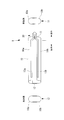
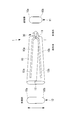
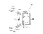
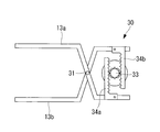
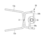
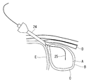
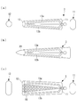
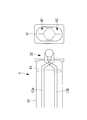
- FIG. 4 is a partially enlarged view of the adjustment mechanism of FIG. 3. It is a figure which shows the state at the time of reducing the front end side opening part of the adjustment mechanism of FIG. It is a figure which shows the state at the time of enlarging the front end side opening part of the adjustment mechanism of FIG. It is a figure which shows the state of the preparation stage which inserts the guide sheath of FIG. 1 in a body cavity.
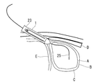
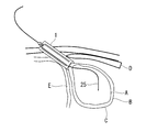
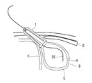
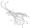
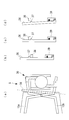
- FIGS. 2A and 2B are diagrams showing changes in the state of the guide sheath of FIG. 1, (a) when a dilator is inserted, (b) when normal, (c) when the distal end side opening is expanded, and (d) when inserting the insertion portion.
- FIG. It is a schematic block diagram of the guide sheath which concerns on a 1st modification. It is a figure which shows the state at the time of enlarging the front end side opening part of the guide sheath of FIG.
- the guide sheath 1 according to an embodiment of the present invention is a cylindrical guide sheath that guides an insertion portion of a medical instrument to be inserted into a body cavity.
- an endoscope or treatment is performed in the pericardial cavity C formed between the heart A and the pericardium B using the guide sheath 1 according to the present embodiment.
- a case where a plurality of insertion portions such as tools are inserted will be described as an example.
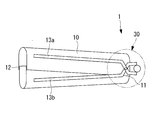
- the guide sheath 1 includes a cylindrical guide sheath body 10, a proximal end opening 11 provided on the proximal end side of the guide sheath body 10, and a guide sheath body. 10 is provided with a front end side opening 12 provided on the front end side of 10 and an adjustment mechanism 30 for adjusting the opening area of the front end side opening 12.
- the guide sheath body 10 is a tube-shaped cylindrical member made of, for example, resin and having flexibility.
- the guide sheath body 10 is configured by fitting a pair of half-cylindrical guide sheath divided bodies 10a and 10b.
- the guide sheath body 10 has, for example, an oval transverse cross-sectional shape having a major axis of 18 mm and a minor axis of 8 mm, and has an insertion passage that extends linearly in the axial direction.
- the guide sheath main body 10 has a length of 20 cm, for example.
- Each of the pair of guide sheath divided bodies 10a and 10b is composed of an elastic body.
- skeleton parts 13a and 13b made of a rigid body are respectively provided in the longitudinal direction.
- the skeleton parts 13a and 13b have a curved shape in the direction in which they approach each other on the base end side.
- the skeleton portions 13a and 13b are connected to each other so as to be relatively rotatable by a rotation support portion 31 of the adjustment mechanism 30 on the proximal end side, as will be described later.
- the proximal end side opening 11 is an opening provided on the proximal end side of the guide sheath body 10. An insertion portion of an endoscope, a treatment instrument, and the like are inserted into the proximal end side opening portion 11.
- the distal end side opening 12 is an opening provided on the distal end side of the guide sheath body 10. An endoscope insertion portion, treatment instrument, and the like that have been inserted through the guide sheath main body 10 are led out to the distal end side opening portion 12. As will be described later, the opening area of the front end opening 12 is adjusted.
- the adjustment mechanism 30 is provided on the proximal end side of the guide sheath body 10 and connected to the skeleton parts 13a and 13b as shown in FIG. A partially enlarged view of the adjusting mechanism 30 shown in FIG. 3 is shown in FIG.
- the adjustment mechanism 30 includes a rotation support portion 31 provided on the base end side of the skeleton portions 13 a and 13 b (guide sheath divided bodies 10 a and 10 b), and a skeleton portion centering on the rotation support portion 31. And a rotation operation unit 32 that relatively rotates 13a and 13b.
- the rotation support part 31 is a pin for connecting the skeleton parts 13a and 13b, and the skeleton parts 13a and 13b (and the guide sheath divided bodies 10a and 10b joined to the skeleton parts 13a and 13b) in the insertion direction of the insertion part. It is supported so as to be capable of relative rotation about an orthogonal axis (axis perpendicular to the paper surface).
- the rotation operation unit 32 is, for example, a dial.
- the skeleton parts 13 a and 13 b and the guide sheath divided bodies 10 a and 10 b joined to the skeleton parts 13 a and 13 b) and the rotation support part 31 are rotated. It is designed to rotate relative to the center.
- the adjustment mechanism 30 has a rack and pinion structure, and a pinion portion 33 is provided coaxially on the rotation shaft of the rotation operation portion 32, and the skeleton portion 13 a. , 13b are provided in parallel with rack portions 34a, 34b that fit into the pinion portion 33, respectively.
- the major axis of the distal end side opening 12 of the guide sheath body 10 is expanded (for example, 30 mm).
- the opening area of the proximal end opening 11 is not changed, and the guide sheath body 10 expands in a fan shape.
- a dilator 23 and guide wires 25 and 26 inserted into the guide sheath 1 are used.
- the dilator 23 is a rod-like member that is inserted into the guide sheath 1 from the proximal end side opening 11 (see FIG. 14A).
- the dilator 23 is inserted into the guide sheath 1 along the guide wire 25 previously placed in the guide sheath 1.
- the tip of the dilator 23 is tapered so that it can enter while expanding the hole in the pericardium B.
- the dilator 23 is preferably formed of a resin having biocompatibility in order to suppress invasion to the tissue in the body cavity.
- the guide wires 25 and 26 are wires that are inserted into the guide sheath 1 from the proximal opening 11, led out from the distal opening 12, and inserted into the pericardial cavity C (see FIG. 12).
- the guide wires 25 and 26 guide the dilator 23 and the insertion portions 20 and 21 from the proximal end side opening 11 to the distal end side opening 12 of the guide sheath 1.
- the guide wires 25 and 26 guide the dilator 23 and the guide sheath 1 into the body cavity.
- the trocar 24 is inserted into the body cavity between the rib D and the diaphragm E from the skin surface. Insert inside. Then, the first guide wire 25 is inserted into the pericardial cavity C via the trocar 24.
- the guide sheath 1 and the dilator 23 are integrated and inserted into the body cavity.
- the flexible guide sheath 1 is formed by inserting a rod-shaped dilator 23 from the proximal end side opening 11 to the distal end side opening 12, as shown in FIG. 23 is regulated in a straight line shape.
- the guide sheath 1 and the dilator 23 can be easily inserted into the body cavity along the guide wire 25.
- the distal end portions of the guide sheath 1 and the dilator 23 are disposed in the body cavity, and the proximal end portion of the guide sheath 1 is disposed outside the body cavity.
- the dilator 23 is pulled out from the guide sheath 1, and the distal end portion of the guide sheath 1 is pressed against the pericardium B.
- the state of the guide sheath 1 in this case is shown in FIG.
- the adjustment mechanism 30 is operated to widen the opening area of the distal end side opening 12 of the guide sheath body 10.
- the state of the guide sheath 1 in this case is shown in FIG.
- insertion of the endoscope is performed by inserting the insertion portion 20 of the first endoscope along the guide wire 25 from the proximal end side opening portion 11 of the guide sheath 1.
- the part 20 passes through the guide sheath 1 and is led out from the distal opening 12, and the insertion part 20 of the endoscope is inserted into the pericardial cavity C.
- the second guide wire 26 is inserted into the pericardial cavity C.
- insertion of the endoscope is performed by inserting the insertion portion 21 of the second endoscope along the guide wire 26 from the proximal end side opening portion 11 of the guide sheath 1.
- the portion 21 passes through the guide sheath 1 and is led out from the distal opening 12, and the insertion portion 21 of the endoscope is inserted into the pericardial cavity C.
- the state of the guide sheath 1 in this case is shown in FIG.
- the adjustment mechanism 30 increases the opening area of the distal end side opening 12 of the guide sheath main body 10, whereby a plurality of insertion portions 20 are inserted into the guide sheath main body 10. , 21 can be inserted, the interval between the insertion portions 20, 21 can be widened.
- interval of the several through-hole formed in the pericardium B can be made into predetermined magnitude
- the skin surface is not cut more than necessary, Invasion to the human body can be minimized.
- the guide sheath body 10 is constituted by the semi-cylindrical guide sheath divided bodies 10 a and 10 b, so that the guide sheath divided bodies 10 a and 10 b are relatively moved around the rotation support section 31 by the rotation operation unit 32. By rotating, the opening area of the distal end side opening 12 can be adjusted. At this time, the guide sheath body 10 maintains a linear shape from the proximal end opening 11 to the distal opening 12. Thereby, even when a rigid treatment instrument is used as the insertion portions 20 and 21, these treatment instruments can be inserted into the pericardial cavity C at intended intervals.
- the guide sheath divided bodies 10a and 10b with the skeleton portions 13a and 13b made of a rigid body, even when pressure is applied to the guide sheath main body 10 in the body cavity, the skeleton portions 13a and 13b cause the distal side
- the opening 12 can be maintained at a predetermined opening area, and when inserting a plurality of insertion portions, the insertion portions can be inserted into the pericardial cavity C at an intended interval.
- the guide sheath divided bodies 10a and 10b may be configured to have such strength that the cross-sectional area is not deformed by the pressure in the body cavity.
- the rotation operation unit 32 does not easily move due to external force unless the dial (rotation operation unit 32) is turned, and the opening area of the distal end side opening 12 is increased. Can be kept stable. Further, the opening area of the distal end side opening 12 of the guide sheath body 10 can be adjusted with high accuracy and reliability.
- channel separation walls 14 a and 14 b for determining the positions of the insertion portions 20 and 21 are provided inside the guide sheath body 10. Yes.
- the channel separation walls 14 a and 14 b are configured to restrict the insertion portions 20 and 21 from moving inward in the major axis direction when the insertion portions 20 and 21 are inserted into the guide sheath body 10.
- the channel separation walls 14a and 14b are provided in pairs in the minor axis direction on the guide sheath divided bodies 10a and 10b, respectively, inside the guide sheath body 10. Further, the channel separation walls 14 a and 14 b are provided to extend in the longitudinal direction of the guide sheath body 10 inside the guide sheath body 10.
- the channel separation walls 14a and 14b have the channel separation wall 14a according to the distal end side when the adjustment mechanism 30 is operated to widen the opening area of the distal end side opening portion 12. And the channel separation wall 14b are separated from each other. That is, the interval between the insertion paths (channels) of the insertion portions 20 and 21 in the guide sheath body 10 is widened while maintaining the original channel width.
- the guide sheath 2 when the opening area of the distal end side opening portion 12 is increased in a state where the guide sheath body 10 is inserted into the body cavity, and the interval between the plurality of insertion portions is widened, This interval can be maintained by the channel separation walls 14a and 14b, and these insertion portions can be inserted into the pericardial cavity C at an intended interval.
- the channel separation walls 14a and 14b are described as being provided in pairs in the minor axis direction inside the guide sheath body 10, but the wall body that partitions the guide sheath body 10 in the major axis direction. It is good.
- a normal state (a state where the opening area of the distal end side opening 12 is small) is used.
- the distal end side opening 12 may have a shape that is tapered as compared with the proximal end side opening 11.
- the workability at the time of inserting the guide sheath body 10 into the body cavity is reduced by reducing the opening area of the distal end side opening 12 by the adjustment mechanism 30. Can be improved.
- an extended portion 18 such as a bellows may be provided on the side surface of the guide sheath body 10.
- the adjustment range of the opening area of the distal end side opening 12 can be increased, the distal end side opening 12 is made smaller when inserted into the body cavity, and the distal end when the insertion portions 20 and 21 are inserted.
- the side opening 12 can be expanded so that the insertion portions 20 and 21 have a desired interval.
- the sealing part 41 is made of, for example, silicon resin, and is provided with slits 42 and 43 through which the insertion parts 20 and 21 are inserted.
- the slits 42 and 43 are brought into close contact with the insertion portions 20 and 21 by the elasticity of the silicon resin, thereby maintaining airtightness.
- the sealing portion 41 can maintain airtightness in the body cavity in a state where the insertion portions 20 and 21 are inserted into the guide sheath body 10 placed in the body cavity. ing.
- the sealing portion 41 is removed when the trocar 24 and the dilator 23 are inserted, and is fitted inside the guide sheath body 10 when the insertion portions 20 and 21 are inserted.
- airtightness in the body cavity can be maintained by the sealing portion 41 in a state where the insertion portions 20 and 21 are inserted into the guide sheath body 10 placed in the body cavity.
- FIGS. 19A to 19D As a fourth modification of the guide sheath 1 according to this embodiment, as shown in FIGS. 19A to 19D, the adjustment mechanism 30 maintains the opening area of the distal end side opening 12.
- a lock mechanism may be provided.
- FIG. 19A is a partially enlarged view of the adjusting mechanism 30 according to this modification
- FIGS. 19B to 19C are partially enlarged views of the lock lever 36 of FIG. 19A. is there.
- the adjustment mechanism 30 includes a lock lever 36 connected to the skeleton part 13a, a protrusion 37 formed on the lock lever 36, a fitting part 38 provided on the skeleton part 13b and fitted to the protrusion 37, a lock And a spring portion 39 that maintains the lever 36 at a predetermined angle by an elastic force.
- the lock of the adjusting mechanism 30 is released.
- the lock lever 36 is tilted against the elastic force of the spring portion 39 to release the fitting of the protruding portion 37 to the fitting portion 38.
- the adjustment mechanism 30 can be operated and the opening area of the front end side opening part 12 can be made small.
- the guide sheath 5 it is possible to prevent the opening area of the distal end side opening portion 12 from changing unintentionally in a state where the guide sheath body 10 is inserted into the body cavity, and the insertion portion An interval between 20, 21 can be maintained.
- the insertion portion of the endoscope is inserted into the pericardial cavity using the guide sheath according to the present invention
- the guide sheath according to the present invention may be inserted into another body cavity.
- the example which inserts two insertion parts in a guide sheath was demonstrated, it is good also as inserting three or more insertion parts.
Landscapes
- Health & Medical Sciences (AREA)
- Life Sciences & Earth Sciences (AREA)
- Surgery (AREA)
- Biomedical Technology (AREA)
- Heart & Thoracic Surgery (AREA)
- Animal Behavior & Ethology (AREA)
- General Health & Medical Sciences (AREA)
- Public Health (AREA)
- Veterinary Medicine (AREA)
- Engineering & Computer Science (AREA)
- Medical Informatics (AREA)
- Molecular Biology (AREA)
- Nuclear Medicine, Radiotherapy & Molecular Imaging (AREA)
- Hematology (AREA)
- Anesthesiology (AREA)
- Physics & Mathematics (AREA)
- Biophysics (AREA)
- Optics & Photonics (AREA)
- Pathology (AREA)
- Radiology & Medical Imaging (AREA)
- Endoscopes (AREA)
- Media Introduction/Drainage Providing Device (AREA)
- Surgical Instruments (AREA)
Abstract
L'invention porte sur un manchon de guidage, par lequel manchon une pluralité d'éléments d'insertion peuvent être facilement guidés dans une cavité corporelle. Un manchon de guidage tubulaire (1) sert à guider des éléments d'insertion d'un instrument médical qui doit être inséré dans une cavité corporelle, ledit manchon de guidage (1) comprenant : une ouverture (11) dans un côté d'extrémité de base, qui est formée dans le côté d'extrémité de base d'un corps de manchon de guidage (10) et à travers laquelle sont acheminés vers l'intérieur une pluralité d'éléments d'insertion ; une ouverture (12) dans le côté d'extrémité avant, qui est formée dans le côté d'extrémité avant du corps de manchon de guidage (10), et à travers laquelle une pluralité d'éléments d'insertion sont acheminés vers l'extérieur ; et un mécanisme d'ajustement (30) qui ajuste la surface d'ouverture de l'ouverture (12) dans le côté d'extrémité avant.
Applications Claiming Priority (2)
| Application Number | Priority Date | Filing Date | Title |
|---|---|---|---|
| JP2011095191A JP2012223443A (ja) | 2011-04-21 | 2011-04-21 | ガイドシース |
| JP2011-095191 | 2011-04-21 |
Publications (1)
| Publication Number | Publication Date |
|---|---|
| WO2012144348A1 true WO2012144348A1 (fr) | 2012-10-26 |
Family
ID=47041460
Family Applications (1)
| Application Number | Title | Priority Date | Filing Date |
|---|---|---|---|
| PCT/JP2012/059510 Ceased WO2012144348A1 (fr) | 2011-04-21 | 2012-04-06 | Manchon de guidage |
Country Status (2)
| Country | Link |
|---|---|
| JP (1) | JP2012223443A (fr) |
| WO (1) | WO2012144348A1 (fr) |
Citations (3)
| Publication number | Priority date | Publication date | Assignee | Title |
|---|---|---|---|---|
| JP2005530586A (ja) * | 2002-06-26 | 2005-10-13 | エスディージーアイ・ホールディングス・インコーポレーテッド | 侵襲性を最小にする組織牽引及び外科処置のための器具と方法 |
| JP2009531081A (ja) * | 2006-03-17 | 2009-09-03 | ボエッジ メディカル, インコーポレイテッド | 組織可視化および操作システム |
| JP2010508959A (ja) * | 2006-11-09 | 2010-03-25 | エヌコンタクト サージカル, インコーポレイテッド | 後部外科アクセスのための横隔膜進入 |
-
2011
- 2011-04-21 JP JP2011095191A patent/JP2012223443A/ja active Pending
-
2012
- 2012-04-06 WO PCT/JP2012/059510 patent/WO2012144348A1/fr not_active Ceased
Patent Citations (3)
| Publication number | Priority date | Publication date | Assignee | Title |
|---|---|---|---|---|
| JP2005530586A (ja) * | 2002-06-26 | 2005-10-13 | エスディージーアイ・ホールディングス・インコーポレーテッド | 侵襲性を最小にする組織牽引及び外科処置のための器具と方法 |
| JP2009531081A (ja) * | 2006-03-17 | 2009-09-03 | ボエッジ メディカル, インコーポレイテッド | 組織可視化および操作システム |
| JP2010508959A (ja) * | 2006-11-09 | 2010-03-25 | エヌコンタクト サージカル, インコーポレイテッド | 後部外科アクセスのための横隔膜進入 |
Also Published As
| Publication number | Publication date |
|---|---|
| JP2012223443A (ja) | 2012-11-15 |
Similar Documents
| Publication | Publication Date | Title |
|---|---|---|
| JP5730873B2 (ja) | 偏向可能な処置器具用ポート部 | |
| JP5091229B2 (ja) | 経管腔的外科手術システム | |
| JP6344828B2 (ja) | アクセスデバイスおよび該デバイスを備えたアセンブリ | |
| JP2012518478A (ja) | マルチ処置器具を備えたアクセス装置およびシステム | |
| JP4902017B2 (ja) | 医療用マニピュレータ | |
| US11007347B2 (en) | Deflectable insertion tool | |
| JP2004195037A (ja) | 医療用処置器具の挿入ポート | |
| JP2016540572A5 (fr) | ||
| JP6177021B2 (ja) | 内視鏡 | |
| US20140039387A1 (en) | Guide tube for microsurgical instruments | |
| JP2005046274A (ja) | 内視鏡挿入用補助具 | |
| US10933214B2 (en) | Method for producing a deflectable insertion tool | |
| WO2019030848A1 (fr) | Instrument de traitement | |
| WO2020121438A1 (fr) | Unité de canal d'endoscope et endoscope | |
| JP4841821B2 (ja) | 組織に対する手術手技用のアプライヤー | |
| JP2005103277A5 (fr) | ||
| KR101750628B1 (ko) | 내시경 장비에 부착된 수술 팔을 포함하는 수술용 장치 및 이를 포함하는 수술 시스템 | |
| JP2011136175A (ja) | 内視鏡装置 | |
| JP2012223443A (ja) | ガイドシース | |
| JP4344734B2 (ja) | 医療用処理器具の挿入ポート | |
| US9687270B2 (en) | Instrument system for minimally invasive surgery in single port technology | |
| WO2023032145A1 (fr) | Appareil de traitement, dispositif de manipulation d'outil de traitement, système de traitement et procédé de manipulation d'outil de traitement | |
| JP6747800B2 (ja) | 処置具挿通具 | |
| KR102486623B1 (ko) | 최소침습 척추수술을 위한 비원형 확장기 유닛 | |
| KR20210055163A (ko) | 척추 내시경 수술용 확장형 시스 |
Legal Events
| Date | Code | Title | Description |
|---|---|---|---|
| 121 | Ep: the epo has been informed by wipo that ep was designated in this application |
Ref document number: 12773605 Country of ref document: EP Kind code of ref document: A1 |
|
| NENP | Non-entry into the national phase |
Ref country code: DE |
|
| 122 | Ep: pct application non-entry in european phase |
Ref document number: 12773605 Country of ref document: EP Kind code of ref document: A1 |