WO2012144348A1 - ガイドシース - Google Patents
ガイドシース Download PDFInfo
- Publication number
- WO2012144348A1 WO2012144348A1 PCT/JP2012/059510 JP2012059510W WO2012144348A1 WO 2012144348 A1 WO2012144348 A1 WO 2012144348A1 JP 2012059510 W JP2012059510 W JP 2012059510W WO 2012144348 A1 WO2012144348 A1 WO 2012144348A1
- Authority
- WO
- WIPO (PCT)
- Prior art keywords
- guide sheath
- end side
- opening
- distal end
- side opening
- Prior art date
- Legal status (The legal status is an assumption and is not a legal conclusion. Google has not performed a legal analysis and makes no representation as to the accuracy of the status listed.)
- Ceased
Links
Images



Classifications
-
- A—HUMAN NECESSITIES
- A61—MEDICAL OR VETERINARY SCIENCE; HYGIENE
- A61B—DIAGNOSIS; SURGERY; IDENTIFICATION
- A61B1/00—Instruments for performing medical examinations of the interior of cavities or tubes of the body by visual or photographical inspection, e.g. endoscopes; Illuminating arrangements therefor
- A61B1/00131—Accessories for endoscopes
- A61B1/00135—Oversleeves mounted on the endoscope prior to insertion
-
- A—HUMAN NECESSITIES
- A61—MEDICAL OR VETERINARY SCIENCE; HYGIENE
- A61B—DIAGNOSIS; SURGERY; IDENTIFICATION
- A61B17/00—Surgical instruments, devices or methods
- A61B17/02—Surgical instruments, devices or methods for holding wounds open, e.g. retractors; Tractors
- A61B17/0218—Surgical instruments, devices or methods for holding wounds open, e.g. retractors; Tractors for minimally invasive surgery
-
- A—HUMAN NECESSITIES
- A61—MEDICAL OR VETERINARY SCIENCE; HYGIENE
- A61M—DEVICES FOR INTRODUCING MEDIA INTO, OR ONTO, THE BODY; DEVICES FOR TRANSDUCING BODY MEDIA OR FOR TAKING MEDIA FROM THE BODY; DEVICES FOR PRODUCING OR ENDING SLEEP OR STUPOR
- A61M29/00—Dilators with or without means for introducing media, e.g. remedies
-
- A—HUMAN NECESSITIES
- A61—MEDICAL OR VETERINARY SCIENCE; HYGIENE
- A61B—DIAGNOSIS; SURGERY; IDENTIFICATION
- A61B17/00—Surgical instruments, devices or methods
- A61B17/02—Surgical instruments, devices or methods for holding wounds open, e.g. retractors; Tractors
- A61B17/0206—Surgical instruments, devices or methods for holding wounds open, e.g. retractors; Tractors with antagonistic arms as supports for retractor elements
-
- A—HUMAN NECESSITIES
- A61—MEDICAL OR VETERINARY SCIENCE; HYGIENE
- A61B—DIAGNOSIS; SURGERY; IDENTIFICATION
- A61B17/00—Surgical instruments, devices or methods
- A61B17/34—Trocars; Puncturing needles
- A61B17/3417—Details of tips or shafts, e.g. grooves, expandable, bendable; Multiple coaxial sliding cannulas, e.g. for dilating
- A61B17/3421—Cannulas
- A61B17/3439—Cannulas with means for changing the inner diameter of the cannula, e.g. expandable
Definitions
- the present invention relates to a guide sheath for guiding an insertion portion of a medical instrument into a body cavity.
- a guide sheath that is used in the medical field, and guides the insertion portion into a body cavity when the insertion portion of a medical instrument such as an endoscope or a treatment instrument is inserted into the body cavity.
- a medical instrument such as an endoscope or a treatment instrument
- the guide sheath disclosed in Patent Document 1 includes a fastening part that fastens to the surface of an organ, a treatment tool fixing part that fixes a distal end position of a treatment tool that performs treatment on the organ, and a treatment tool to the treatment tool fixing part. And a guide unit for guiding.
- this guide sheath when the surgical treatment instrument is guided to the target organ, the fastening portion is expanded at a position where the distal end of the guide sheath contacts the organ, and a flexible endoscope or treatment tool is fixed to the fastening portion. By doing so, a predetermined treatment is performed.
- the present invention has been made in view of the above-described circumstances, and an object thereof is to provide a guide sheath capable of easily guiding a plurality of insertion portions into a body cavity.
- One aspect of the present invention is a cylindrical guide sheath that guides an insertion portion of a medical device to be inserted into a body cavity, and is provided on the proximal end side of the guide sheath, and a plurality of the insertion portions are introduced.
- a guide sheath comprising a proximal end opening, a distal end opening provided on the distal end side of the guide sheath, from which a plurality of the insertion portions are led out, and an adjustment mechanism for adjusting an opening area of the distal end opening. It is.
- the distal end portion of the guide sheath is disposed in the body cavity, and the base of the guide sheath is disposed. The end is placed outside the body cavity. In this state, by inserting the insertion portion from the proximal end opening of the guide sheath, the insertion portion is led out from the distal opening through the guide sheath, and the insertion portion is inserted into the pericardial cavity.
- the workability when inserting the guide sheath into the body cavity can be improved by reducing the opening area of the opening on the distal end side by the adjusting mechanism.
- the adjustment mechanism increases the opening area of the distal end opening of the guide sheath, so that the insertion portions when the plurality of insertion portions are inserted into the guide sheath The interval can be increased.
- interval of the several through-hole formed in a pericardium can be made into predetermined size, and the space
- the skin surface is not cut more than necessary, minimizing the invasion to the human body. Can be fastened.
- a pair of guide sheath divided bodies each constituted by a half cylinder member is provided, the adjustment mechanism is provided on a proximal end side of the pair of guide sheath divided bodies, and the pair of guide sheath divided bodies are A rotation support section that supports the rotation support section so as to be relatively rotatable about an axis perpendicular to the insertion direction of the insertion section; and a rotation operation section that relatively rotates the pair of guide sheath divided bodies around the rotation support section. Also good.
- the rotation operation portion causes the pair of guide sheath divided bodies each formed of the half-cylindrical member to relatively rotate around the rotation support portion, thereby opening the distal end side opening portion.
- the area can be adjusted.
- the guide sheath maintains a linear shape from the proximal end side opening portion to the distal end side opening portion.
- the said guide sheath division body is good also as providing the frame
- the guide sheath divided body may have a deformation resistance greater than the pressure in the body cavity.
- the said aspect WHEREIN It is good also as providing the control mechanism which is provided inside the said guide sheath and controls the position of the said some insertion part in the said guide sheath.
- the said aspect WHEREIN It is good also as providing the sealing part which is provided inside the said guide sheath and seals the clearance gap between the said insertion part and the said guide sheath inner wall surface.
- the said aspect WHEREIN It is good also as the said front end side opening part being formed smaller than the said base end side opening part.
- the adjustment mechanism may include a rack and pinion mechanism.
- the said adjustment mechanism is good also as providing the lock mechanism which maintains the opening area of the said front end side opening part.
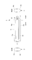
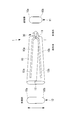
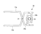
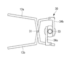
- FIG. 4 is a partially enlarged view of the adjustment mechanism of FIG. 3. It is a figure which shows the state at the time of reducing the front end side opening part of the adjustment mechanism of FIG. It is a figure which shows the state at the time of enlarging the front end side opening part of the adjustment mechanism of FIG. It is a figure which shows the state of the preparation stage which inserts the guide sheath of FIG. 1 in a body cavity.
- FIGS. 2A and 2B are diagrams showing changes in the state of the guide sheath of FIG. 1, (a) when a dilator is inserted, (b) when normal, (c) when the distal end side opening is expanded, and (d) when inserting the insertion portion.
- FIG. It is a schematic block diagram of the guide sheath which concerns on a 1st modification. It is a figure which shows the state at the time of enlarging the front end side opening part of the guide sheath of FIG.
- the guide sheath 1 according to an embodiment of the present invention is a cylindrical guide sheath that guides an insertion portion of a medical instrument to be inserted into a body cavity.
- an endoscope or treatment is performed in the pericardial cavity C formed between the heart A and the pericardium B using the guide sheath 1 according to the present embodiment.
- a case where a plurality of insertion portions such as tools are inserted will be described as an example.
- the guide sheath 1 includes a cylindrical guide sheath body 10, a proximal end opening 11 provided on the proximal end side of the guide sheath body 10, and a guide sheath body. 10 is provided with a front end side opening 12 provided on the front end side of 10 and an adjustment mechanism 30 for adjusting the opening area of the front end side opening 12.
- the guide sheath body 10 is a tube-shaped cylindrical member made of, for example, resin and having flexibility.
- the guide sheath body 10 is configured by fitting a pair of half-cylindrical guide sheath divided bodies 10a and 10b.
- the guide sheath body 10 has, for example, an oval transverse cross-sectional shape having a major axis of 18 mm and a minor axis of 8 mm, and has an insertion passage that extends linearly in the axial direction.
- the guide sheath main body 10 has a length of 20 cm, for example.
- Each of the pair of guide sheath divided bodies 10a and 10b is composed of an elastic body.
- skeleton parts 13a and 13b made of a rigid body are respectively provided in the longitudinal direction.
- the skeleton parts 13a and 13b have a curved shape in the direction in which they approach each other on the base end side.
- the skeleton portions 13a and 13b are connected to each other so as to be relatively rotatable by a rotation support portion 31 of the adjustment mechanism 30 on the proximal end side, as will be described later.
- the proximal end side opening 11 is an opening provided on the proximal end side of the guide sheath body 10. An insertion portion of an endoscope, a treatment instrument, and the like are inserted into the proximal end side opening portion 11.
- the distal end side opening 12 is an opening provided on the distal end side of the guide sheath body 10. An endoscope insertion portion, treatment instrument, and the like that have been inserted through the guide sheath main body 10 are led out to the distal end side opening portion 12. As will be described later, the opening area of the front end opening 12 is adjusted.
- the adjustment mechanism 30 is provided on the proximal end side of the guide sheath body 10 and connected to the skeleton parts 13a and 13b as shown in FIG. A partially enlarged view of the adjusting mechanism 30 shown in FIG. 3 is shown in FIG.
- the adjustment mechanism 30 includes a rotation support portion 31 provided on the base end side of the skeleton portions 13 a and 13 b (guide sheath divided bodies 10 a and 10 b), and a skeleton portion centering on the rotation support portion 31. And a rotation operation unit 32 that relatively rotates 13a and 13b.
- the rotation support part 31 is a pin for connecting the skeleton parts 13a and 13b, and the skeleton parts 13a and 13b (and the guide sheath divided bodies 10a and 10b joined to the skeleton parts 13a and 13b) in the insertion direction of the insertion part. It is supported so as to be capable of relative rotation about an orthogonal axis (axis perpendicular to the paper surface).
- the rotation operation unit 32 is, for example, a dial.
- the skeleton parts 13 a and 13 b and the guide sheath divided bodies 10 a and 10 b joined to the skeleton parts 13 a and 13 b) and the rotation support part 31 are rotated. It is designed to rotate relative to the center.
- the adjustment mechanism 30 has a rack and pinion structure, and a pinion portion 33 is provided coaxially on the rotation shaft of the rotation operation portion 32, and the skeleton portion 13 a. , 13b are provided in parallel with rack portions 34a, 34b that fit into the pinion portion 33, respectively.
- the major axis of the distal end side opening 12 of the guide sheath body 10 is expanded (for example, 30 mm).
- the opening area of the proximal end opening 11 is not changed, and the guide sheath body 10 expands in a fan shape.
- a dilator 23 and guide wires 25 and 26 inserted into the guide sheath 1 are used.
- the dilator 23 is a rod-like member that is inserted into the guide sheath 1 from the proximal end side opening 11 (see FIG. 14A).
- the dilator 23 is inserted into the guide sheath 1 along the guide wire 25 previously placed in the guide sheath 1.
- the tip of the dilator 23 is tapered so that it can enter while expanding the hole in the pericardium B.
- the dilator 23 is preferably formed of a resin having biocompatibility in order to suppress invasion to the tissue in the body cavity.
- the guide wires 25 and 26 are wires that are inserted into the guide sheath 1 from the proximal opening 11, led out from the distal opening 12, and inserted into the pericardial cavity C (see FIG. 12).
- the guide wires 25 and 26 guide the dilator 23 and the insertion portions 20 and 21 from the proximal end side opening 11 to the distal end side opening 12 of the guide sheath 1.
- the guide wires 25 and 26 guide the dilator 23 and the guide sheath 1 into the body cavity.
- the trocar 24 is inserted into the body cavity between the rib D and the diaphragm E from the skin surface. Insert inside. Then, the first guide wire 25 is inserted into the pericardial cavity C via the trocar 24.
- the guide sheath 1 and the dilator 23 are integrated and inserted into the body cavity.
- the flexible guide sheath 1 is formed by inserting a rod-shaped dilator 23 from the proximal end side opening 11 to the distal end side opening 12, as shown in FIG. 23 is regulated in a straight line shape.
- the guide sheath 1 and the dilator 23 can be easily inserted into the body cavity along the guide wire 25.
- the distal end portions of the guide sheath 1 and the dilator 23 are disposed in the body cavity, and the proximal end portion of the guide sheath 1 is disposed outside the body cavity.
- the dilator 23 is pulled out from the guide sheath 1, and the distal end portion of the guide sheath 1 is pressed against the pericardium B.
- the state of the guide sheath 1 in this case is shown in FIG.
- the adjustment mechanism 30 is operated to widen the opening area of the distal end side opening 12 of the guide sheath body 10.
- the state of the guide sheath 1 in this case is shown in FIG.
- insertion of the endoscope is performed by inserting the insertion portion 20 of the first endoscope along the guide wire 25 from the proximal end side opening portion 11 of the guide sheath 1.
- the part 20 passes through the guide sheath 1 and is led out from the distal opening 12, and the insertion part 20 of the endoscope is inserted into the pericardial cavity C.
- the second guide wire 26 is inserted into the pericardial cavity C.
- insertion of the endoscope is performed by inserting the insertion portion 21 of the second endoscope along the guide wire 26 from the proximal end side opening portion 11 of the guide sheath 1.
- the portion 21 passes through the guide sheath 1 and is led out from the distal opening 12, and the insertion portion 21 of the endoscope is inserted into the pericardial cavity C.
- the state of the guide sheath 1 in this case is shown in FIG.
- the adjustment mechanism 30 increases the opening area of the distal end side opening 12 of the guide sheath main body 10, whereby a plurality of insertion portions 20 are inserted into the guide sheath main body 10. , 21 can be inserted, the interval between the insertion portions 20, 21 can be widened.
- interval of the several through-hole formed in the pericardium B can be made into predetermined magnitude
- the skin surface is not cut more than necessary, Invasion to the human body can be minimized.
- the guide sheath body 10 is constituted by the semi-cylindrical guide sheath divided bodies 10 a and 10 b, so that the guide sheath divided bodies 10 a and 10 b are relatively moved around the rotation support section 31 by the rotation operation unit 32. By rotating, the opening area of the distal end side opening 12 can be adjusted. At this time, the guide sheath body 10 maintains a linear shape from the proximal end opening 11 to the distal opening 12. Thereby, even when a rigid treatment instrument is used as the insertion portions 20 and 21, these treatment instruments can be inserted into the pericardial cavity C at intended intervals.
- the guide sheath divided bodies 10a and 10b with the skeleton portions 13a and 13b made of a rigid body, even when pressure is applied to the guide sheath main body 10 in the body cavity, the skeleton portions 13a and 13b cause the distal side
- the opening 12 can be maintained at a predetermined opening area, and when inserting a plurality of insertion portions, the insertion portions can be inserted into the pericardial cavity C at an intended interval.
- the guide sheath divided bodies 10a and 10b may be configured to have such strength that the cross-sectional area is not deformed by the pressure in the body cavity.
- the rotation operation unit 32 does not easily move due to external force unless the dial (rotation operation unit 32) is turned, and the opening area of the distal end side opening 12 is increased. Can be kept stable. Further, the opening area of the distal end side opening 12 of the guide sheath body 10 can be adjusted with high accuracy and reliability.
- channel separation walls 14 a and 14 b for determining the positions of the insertion portions 20 and 21 are provided inside the guide sheath body 10. Yes.
- the channel separation walls 14 a and 14 b are configured to restrict the insertion portions 20 and 21 from moving inward in the major axis direction when the insertion portions 20 and 21 are inserted into the guide sheath body 10.
- the channel separation walls 14a and 14b are provided in pairs in the minor axis direction on the guide sheath divided bodies 10a and 10b, respectively, inside the guide sheath body 10. Further, the channel separation walls 14 a and 14 b are provided to extend in the longitudinal direction of the guide sheath body 10 inside the guide sheath body 10.
- the channel separation walls 14a and 14b have the channel separation wall 14a according to the distal end side when the adjustment mechanism 30 is operated to widen the opening area of the distal end side opening portion 12. And the channel separation wall 14b are separated from each other. That is, the interval between the insertion paths (channels) of the insertion portions 20 and 21 in the guide sheath body 10 is widened while maintaining the original channel width.
- the guide sheath 2 when the opening area of the distal end side opening portion 12 is increased in a state where the guide sheath body 10 is inserted into the body cavity, and the interval between the plurality of insertion portions is widened, This interval can be maintained by the channel separation walls 14a and 14b, and these insertion portions can be inserted into the pericardial cavity C at an intended interval.
- the channel separation walls 14a and 14b are described as being provided in pairs in the minor axis direction inside the guide sheath body 10, but the wall body that partitions the guide sheath body 10 in the major axis direction. It is good.
- a normal state (a state where the opening area of the distal end side opening 12 is small) is used.
- the distal end side opening 12 may have a shape that is tapered as compared with the proximal end side opening 11.
- the workability at the time of inserting the guide sheath body 10 into the body cavity is reduced by reducing the opening area of the distal end side opening 12 by the adjustment mechanism 30. Can be improved.
- an extended portion 18 such as a bellows may be provided on the side surface of the guide sheath body 10.
- the adjustment range of the opening area of the distal end side opening 12 can be increased, the distal end side opening 12 is made smaller when inserted into the body cavity, and the distal end when the insertion portions 20 and 21 are inserted.
- the side opening 12 can be expanded so that the insertion portions 20 and 21 have a desired interval.
- the sealing part 41 is made of, for example, silicon resin, and is provided with slits 42 and 43 through which the insertion parts 20 and 21 are inserted.
- the slits 42 and 43 are brought into close contact with the insertion portions 20 and 21 by the elasticity of the silicon resin, thereby maintaining airtightness.
- the sealing portion 41 can maintain airtightness in the body cavity in a state where the insertion portions 20 and 21 are inserted into the guide sheath body 10 placed in the body cavity. ing.
- the sealing portion 41 is removed when the trocar 24 and the dilator 23 are inserted, and is fitted inside the guide sheath body 10 when the insertion portions 20 and 21 are inserted.
- airtightness in the body cavity can be maintained by the sealing portion 41 in a state where the insertion portions 20 and 21 are inserted into the guide sheath body 10 placed in the body cavity.
- FIGS. 19A to 19D As a fourth modification of the guide sheath 1 according to this embodiment, as shown in FIGS. 19A to 19D, the adjustment mechanism 30 maintains the opening area of the distal end side opening 12.
- a lock mechanism may be provided.
- FIG. 19A is a partially enlarged view of the adjusting mechanism 30 according to this modification
- FIGS. 19B to 19C are partially enlarged views of the lock lever 36 of FIG. 19A. is there.
- the adjustment mechanism 30 includes a lock lever 36 connected to the skeleton part 13a, a protrusion 37 formed on the lock lever 36, a fitting part 38 provided on the skeleton part 13b and fitted to the protrusion 37, a lock And a spring portion 39 that maintains the lever 36 at a predetermined angle by an elastic force.
- the lock of the adjusting mechanism 30 is released.
- the lock lever 36 is tilted against the elastic force of the spring portion 39 to release the fitting of the protruding portion 37 to the fitting portion 38.
- the adjustment mechanism 30 can be operated and the opening area of the front end side opening part 12 can be made small.
- the guide sheath 5 it is possible to prevent the opening area of the distal end side opening portion 12 from changing unintentionally in a state where the guide sheath body 10 is inserted into the body cavity, and the insertion portion An interval between 20, 21 can be maintained.
- the insertion portion of the endoscope is inserted into the pericardial cavity using the guide sheath according to the present invention
- the guide sheath according to the present invention may be inserted into another body cavity.
- the example which inserts two insertion parts in a guide sheath was demonstrated, it is good also as inserting three or more insertion parts.
Landscapes
- Health & Medical Sciences (AREA)
- Life Sciences & Earth Sciences (AREA)
- Surgery (AREA)
- Biomedical Technology (AREA)
- Heart & Thoracic Surgery (AREA)
- Animal Behavior & Ethology (AREA)
- General Health & Medical Sciences (AREA)
- Public Health (AREA)
- Veterinary Medicine (AREA)
- Engineering & Computer Science (AREA)
- Medical Informatics (AREA)
- Molecular Biology (AREA)
- Nuclear Medicine, Radiotherapy & Molecular Imaging (AREA)
- Hematology (AREA)
- Anesthesiology (AREA)
- Physics & Mathematics (AREA)
- Biophysics (AREA)
- Optics & Photonics (AREA)
- Pathology (AREA)
- Radiology & Medical Imaging (AREA)
- Endoscopes (AREA)
- Media Introduction/Drainage Providing Device (AREA)
- Surgical Instruments (AREA)
Abstract
複数の挿入部を体腔内に容易に誘導することができるガイドシースを提供する。体腔内に挿入される医療器具の挿入部を誘導する筒状のガイドシース(1)であって、ガイドシース本体(10)の基端側に設けられ、複数の挿入部が導入される基端側開口部(11)と、ガイドシース本体(10)の先端側に設けられ、複数の挿入部が導出される先端側開口部(12)と、先端側開口部(12)の開口面積を調整する調整機構(30)とを備えるガイドシース(1)を採用する。
Description
本発明は、医療器具の挿入部を体腔内に誘導するガイドシースに関するものである。
従来、医療分野において用いられ、例えば内視鏡や処置具等の医療器具の挿入部を体腔内に挿入する際に、前記挿入部を体腔内に誘導するためのガイドシースが知られている(例えば、特許文献1参照。)。
特許文献1に開示されているガイドシースは、臓器表面に止着する止着部と、臓器に処置を施す処置具の先端位置を固定する処置具固定部と、処置具固定部へ処置具を案内する案内部とを備えている。このガイドシースでは、外科手術用の処置具を対象臓器まで導く際、ガイドシースの先端が臓器に接する位置で止着部を拡張し、該止着部に軟性の内視鏡や処置具を固定することで、所定の処置を行うようになっている。
しかしながら、特許文献1に開示されているガイドシースによれば、複数の挿入部(処置具や内視鏡)を挿入する場合には、これら挿入部を体外から個別に止着部まで誘導する必要がある。このため、体表面に複数のトロッカポートを設ける必要があり、また剣状突起から心膜腔内にアプローチする場合には、心膜腔内と剣状突起との間の小さな空間への挿入部のアプローチが複数回必要になり、狭い空間内の組織を傷つける恐れがあるという不都合がある。
本発明は上述した事情に鑑みてなされたものであって、複数の挿入部を体腔内に容易に誘導することができるガイドシースを提供することを目的としている。
上記目的を達成するために、本発明は以下の手段を採用する。
本発明の一態様は、体腔内に挿入される医療器具の挿入部を誘導する筒状のガイドシースであって、該ガイドシースの基端側に設けられ、複数の前記挿入部が導入される基端側開口部と、前記ガイドシースの先端側に設けられ、複数の前記挿入部が導出される先端側開口部と、前記先端側開口部の開口面積を調整する調整機構とを備えるガイドシースである。
本発明の一態様は、体腔内に挿入される医療器具の挿入部を誘導する筒状のガイドシースであって、該ガイドシースの基端側に設けられ、複数の前記挿入部が導入される基端側開口部と、前記ガイドシースの先端側に設けられ、複数の前記挿入部が導出される先端側開口部と、前記先端側開口部の開口面積を調整する調整機構とを備えるガイドシースである。
上記態様によれば、例えば、内視鏡等の医療器具の挿入部を、心膜腔等の体腔内に挿入するには、ガイドシースの先端部を体腔内に配置するとともに、ガイドシースの基端部を体腔外に配置する。この状態において、ガイドシースの基端側開口部から挿入部を挿入することで、ガイドシース内を通って挿入部が先端側開口部から導出され、挿入部が心膜腔内に挿入される。
この場合において、調整機構により先端側開口部の開口面積を小さくすることで、ガイドシースを体腔内に挿入する際の作業性を向上することができる。また、ガイドシースが体腔内に挿入された状態で、調整機構によりガイドシースの先端側開口部の開口面積を大きくすることで、ガイドシース内に複数の挿入部を挿入した際の挿入部同士の間隔を広げることができる。これにより、心膜に形成する複数の貫通孔の間隔を所定のサイズにすることができ、心膜腔内に挿入する複数の挿入部(処置具)の間隔を、所望の値に正確に合わせることができる。
また、基端側開口部の開口面積は変化させずに先端側開口部の開口面積のみを調整することで、皮膚表面を必要以上に切開することもないため、人体への侵襲を最小限に留めることができる。
上記態様において、半筒部材からそれぞれ構成された一対のガイドシース分割体を備え、前記調整機構が、前記一対のガイドシース分割体の基端側に設けられ、前記一対のガイドシース分割体を前記挿入部の挿入方向に直交する軸線回りに相対回転可能に支持する回転支持部と、該回転支持部を中心として前記一対のガイドシース分割体を相対的に回転させる回転操作部とを備えることとしてもよい。
このような構成を有することで、回転操作部により、半筒部材からそれぞれ構成された一対のガイドシース分割体を、回転支持部を中心として相対的に回転させることによって、先端側開口部の開口面積を調整することができる。また、この際、ガイドシースは、基端側開口部から先端側開口部にかけて直線形状が維持される。これにより、挿入部として硬性の処置具を用いた場合にも、意図した間隔で複数の処置具を心膜腔内に挿入することができる。
上記態様において、前記ガイドシース分割体が、剛体から構成される骨格部と、弾性体から構成される分割体本体とを備えることとしてもよい。
このような構成を有することで、体腔内においてガイドシースに圧力が加えられた場合にも、骨格部により先端側開口部を所定の開口面積に維持することができ、複数の挿入部を挿入する際にも、意図した間隔でこれら処置具を心膜腔内に挿入することができる。
このような構成を有することで、体腔内においてガイドシースに圧力が加えられた場合にも、骨格部により先端側開口部を所定の開口面積に維持することができ、複数の挿入部を挿入する際にも、意図した間隔でこれら処置具を心膜腔内に挿入することができる。
上記態様において、前記ガイドシース分割体が、体腔内の圧力よりも大きな耐変形強度を有することとしてもよい。
このような構成を有することで、体腔内においてガイドシースに圧力が加えられた場合にも、先端側開口部を所定の開口面積に維持することができ、複数の挿入部を挿入する際にも、意図した間隔でこれら処置具を心膜腔内に挿入することができる。
このような構成を有することで、体腔内においてガイドシースに圧力が加えられた場合にも、先端側開口部を所定の開口面積に維持することができ、複数の挿入部を挿入する際にも、意図した間隔でこれら処置具を心膜腔内に挿入することができる。
上記態様において、前記ガイドシースの内側に設けられ、前記ガイドシース内における複数の前記挿入部の位置を規制する規制機構を備えることとしてもよい。
このような構成を有することで、体腔内にガイドシースを挿入した状態で先端側開口部の開口面積を大きくして、複数の挿入部同士の間隔を広げた際に、この間隔を規制機構により維持することができ、意図した間隔でこれら処置具を心膜腔内に挿入することができる。
このような構成を有することで、体腔内にガイドシースを挿入した状態で先端側開口部の開口面積を大きくして、複数の挿入部同士の間隔を広げた際に、この間隔を規制機構により維持することができ、意図した間隔でこれら処置具を心膜腔内に挿入することができる。
上記態様において、前記ガイドシースの内側に設けられ、前記挿入部と前記ガイドシース内壁面との隙間を封止する封止部を備えることとしてもよい。
このような構成を有することで、体腔内に留置されたガイドシース内に挿入部を挿入した状態において、封止部により体腔内の気密を保つことができる。
このような構成を有することで、体腔内に留置されたガイドシース内に挿入部を挿入した状態において、封止部により体腔内の気密を保つことができる。
上記態様において、前記先端側開口部が、前記基端側開口部よりも小さく形成されていることとしてもよい。
このような構成を有することで、ガイドシースを体腔内に挿入する際の作業性を向上することができる。
このような構成を有することで、ガイドシースを体腔内に挿入する際の作業性を向上することができる。
上記態様において、前記調整機構が、ラックアンドピニオン機構を備えることとしてもよい。
このような構成を有することで、先端側開口部の開口面積の調整を高精度且つ確実に行うことができる。
このような構成を有することで、先端側開口部の開口面積の調整を高精度且つ確実に行うことができる。
上記態様において、前記調整機構が、前記先端側開口部の開口面積を維持するロック機構を備えることとしてもよい。
このような構成を有することで、体腔内にガイドシースを挿入した状態において、先端側開口部の開口面積が意図せずに変化することを防止することができ、複数の挿入部同士の間隔を維持することができる。
このような構成を有することで、体腔内にガイドシースを挿入した状態において、先端側開口部の開口面積が意図せずに変化することを防止することができ、複数の挿入部同士の間隔を維持することができる。
本発明によれば、複数の挿入部を体腔内に容易に誘導することができるという効果を奏する。
本発明の一実施形態に係るガイドシース1について図面を参照して以下に説明する。
本実施形態に係るガイドシース1は、図1および図2に示されるように、体腔内に挿入される医療器具の挿入部等を誘導する筒状のガイドシースである。以降では、図7から図13に示されるように、本実施形態に係るガイドシース1を用いて、心臓Aと心膜Bとの間に形成される心膜腔内Cに内視鏡や処置具等の複数の挿入部を挿入する場合を例に挙げて説明する。
本実施形態に係るガイドシース1は、図1および図2に示されるように、体腔内に挿入される医療器具の挿入部等を誘導する筒状のガイドシースである。以降では、図7から図13に示されるように、本実施形態に係るガイドシース1を用いて、心臓Aと心膜Bとの間に形成される心膜腔内Cに内視鏡や処置具等の複数の挿入部を挿入する場合を例に挙げて説明する。
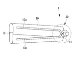
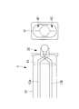
本実施形態に係るガイドシース1は、図1に示されるように、筒状のガイドシース本体10と、ガイドシース本体10の基端側に設けられた基端側開口部11と、ガイドシース本体10の先端側に設けられた先端側開口部12と、先端側開口部12の開口面積を調整する調整機構30とを備えている。
ガイドシース本体10は、例えば樹脂等で構成され、可撓性を有するチューブ状の円筒部材である。ガイドシース本体10は、半筒形状の一対のガイドシース分割体10a,10bが嵌合されて構成されている。ガイドシース本体10は、例えば、長径が18mm、短径が8mmの小判型の横断面形状を有し、軸線方向に直線的に延在する挿通路を有している。また、ガイドシース本体10は、例えば、20cmの長さを有している。
一対のガイドシース分割体10a,10bは、それぞれ弾性体から構成されている。ガイドシース分割体10a,10bの外面には、剛体から構成される骨格部13a,13bが長手方向にそれぞれ設けられている。
骨格部13a,13bは、基端側において、お互いが近接する方向に湾曲した形状とされている。また、骨格部13a,13bは、後述するように、基端側において、調整機構30の回転支持部31により相対回転可能に接続されている。
基端側開口部11は、ガイドシース本体10の基端側に設けられた開口である。基端側開口部11には、内視鏡の挿入部や処置具等が挿入されるようになっている。
先端側開口部12は、ガイドシース本体10の先端側に設けられた開口である。先端側開口部12には、ガイドシース本体10内を挿通してきた、内視鏡の挿入部や処置具等が導出されるようになっている。先端側開口部12は、後述するように、その開口面積が調整されるようになっている。
先端側開口部12は、ガイドシース本体10の先端側に設けられた開口である。先端側開口部12には、ガイドシース本体10内を挿通してきた、内視鏡の挿入部や処置具等が導出されるようになっている。先端側開口部12は、後述するように、その開口面積が調整されるようになっている。
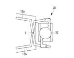
調整機構30は、図3に示されるように、ガイドシース本体10の基端側に設けられ、骨格部13a,13bに接続されている。図3に示す調整機構30の部分拡大図が図4に示されている。
図4に示されるように、調整機構30は、骨格部13a,13b(ガイドシース分割体10a,10b)の基端側に設けられた回転支持部31と、回転支持部31を中心として骨格部13a,13bを相対的に回転させる回転操作部32とを備えている。
回転支持部31は、骨格部13a,13bを接続するピンであり、骨格部13a,13b(および骨格部13a,13bに接合されたガイドシース分割体10a,10b)を、挿入部の挿入方向に直交する軸線(紙面垂直方向の軸線)回りに相対回転可能に支持するようになっている。
回転操作部32は、例えばダイアルであり、ユーザがダイアルを回すことで、骨格部13a,13b(および骨格部13a,13bに接合されたガイドシース分割体10a,10b)を、回転支持部31を中心として相対的に回転させるようになっている。
より具体的には、図5に示されるように、調整機構30は、ラックアンドピニオン構造を有しており、回転操作部32の回転軸にはピニオン部33が同軸に設けられ、骨格部13a,13bの基端側には、それぞれ、ピニオン部33と嵌合するラック部34a,34bが平行に設けられている。
上記構成を有することで、図6に示されるように、ユーザがダイアル(回転操作部32)を回すことで、ピニオン部33を回転させ、ピニオン部33と嵌合するラック部34a,34bを相対移動させるようになっている。これにより、骨格部13a,13b(および骨格部13a,13bに接合されたガイドシース分割体10a,10b)が、回転支持部31を中心として相対的に回転される。
このようにすることで、図2に示されるように、ガイドシース本体10の先端側開口部12の長径が広げられる(例えば30mm)。この場合において、基端側開口部11の開口面積は変化させず、ガイドシース本体10が扇状に広がる。このような構成の調整機構30を用いることで、後述するように、心膜腔内Cに挿入する2本の処置具の間隔を、所望の値(例えば10mm)に正確に合わせることができる。
ガイドシース1を心膜腔内Cに挿入するにあたっては、ガイドシース1内に挿入されるダイレータ23およびガイドワイヤ25,26を用いる。
ダイレータ23は、基端側開口部11からガイドシース1内に挿入される棒状部材である(図14(a)参照)。ダイレータ23は、予めガイドシース1内に留置されているガイドワイヤ25に沿ってガイドシース1内に挿入される。ダイレータ23の先端は、テーパ状になっており、心膜Bの穴を広げながら進入することができるようになっている。なお、ダイレータ23は、体腔内の組織に対する侵襲を抑えるために生体適合性を有する樹脂で形成されていることが望ましい。
ダイレータ23は、基端側開口部11からガイドシース1内に挿入される棒状部材である(図14(a)参照)。ダイレータ23は、予めガイドシース1内に留置されているガイドワイヤ25に沿ってガイドシース1内に挿入される。ダイレータ23の先端は、テーパ状になっており、心膜Bの穴を広げながら進入することができるようになっている。なお、ダイレータ23は、体腔内の組織に対する侵襲を抑えるために生体適合性を有する樹脂で形成されていることが望ましい。
ガイドワイヤ25,26は、基端側開口部11からガイドシース1内に挿入され、先端側開口部12から導出されて、心膜腔内Cに挿入されるワイヤである(図12参照)。ガイドワイヤ25,26は、ダイレータ23および挿入部20,21を、ガイドシース1の基端側開口部11から先端側開口部12まで誘導するようになっている。また、ガイドワイヤ25,26は、ダイレータ23およびガイドシース1を、体腔内に誘導するようになっている。
上記構成を有するガイドシース1を用いて、複数の内視鏡の挿入部20,21を心膜腔内に挿入する際の動作について以下に説明する。
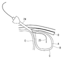
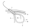
複数の内視鏡の挿入部20,21を、心膜腔内Cに挿入するには、まず、図7に示されるように、皮膚表面からトロッカー24を肋骨Dと横隔膜Eとの間の体腔内に挿入する。そして、トロッカー24を介して1本目のガイドワイヤ25を心膜腔内Cに挿入する。
複数の内視鏡の挿入部20,21を、心膜腔内Cに挿入するには、まず、図7に示されるように、皮膚表面からトロッカー24を肋骨Dと横隔膜Eとの間の体腔内に挿入する。そして、トロッカー24を介して1本目のガイドワイヤ25を心膜腔内Cに挿入する。
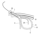
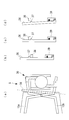
次に、図8に示されるように、ガイドワイヤ25に沿って、ガイドシース1とダイレータ23とを一体化して体腔内に挿入する。この場合において、可撓性を有するガイドシース1は、図14(a)に示されるように、基端側開口部11から先端側開口部12まで棒状のダイレータ23が挿入されることで、ダイレータ23に沿って直線形状に規制されている。
これにより、ガイドワイヤ25に沿って、ガイドシース1とダイレータ23とを容易に体腔内に挿入することができる。このようにすることで、ガイドシース1およびダイレータ23の先端部を体腔内に配置するとともに、ガイドシース1の基端部を体腔外に配置する。
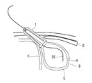
次に、図9に示されるように、ガイドシース1からダイレータ23を引き抜き、ガイドシース1の先端部を心膜Bに押し当てる。この場合におけるガイドシース1の状態が図14(b)に示されている。
次に、図10に示されるように、ユーザがダイアル(回転操作部32)を回すことで、調整機構30を動作させ、ガイドシース本体10の先端側開口部12の開口面積を広げる。この場合におけるガイドシース1の状態が図14(c)に示されている。
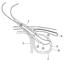
次に、図11に示されるように、ガイドシース1の基端側開口部11から、ガイドワイヤ25に沿って1本目の内視鏡の挿入部20を挿入することで、内視鏡の挿入部20がガイドシース1内を通って先端側開口部12から導出され、内視鏡の挿入部20が心膜腔内Cに挿入される。
次に、図12に示されるように、2本目のガイドワイヤ26を心膜腔内Cに挿入する。
次に、図13に示されるように、ガイドシース1の基端側開口部11から、ガイドワイヤ26に沿って2本目の内視鏡の挿入部21を挿入することで、内視鏡の挿入部21がガイドシース1内を通って先端側開口部12から導出され、内視鏡の挿入部21が心膜腔内Cに挿入される。この場合におけるガイドシース1の状態が図14(d)に示されている。
次に、図13に示されるように、ガイドシース1の基端側開口部11から、ガイドワイヤ26に沿って2本目の内視鏡の挿入部21を挿入することで、内視鏡の挿入部21がガイドシース1内を通って先端側開口部12から導出され、内視鏡の挿入部21が心膜腔内Cに挿入される。この場合におけるガイドシース1の状態が図14(d)に示されている。
以上のように、本実施形態に係るガイドシース1によれば、調整機構30により先端側開口部12の開口面積を小さくすることで、ガイドシース本体10を体腔内に挿入する際の作業性を向上することができる。また、ガイドシース本体10が体腔内に挿入された状態で、調整機構30によりガイドシース本体10の先端側開口部12の開口面積を大きくすることで、ガイドシース本体10内に複数の挿入部20,21を挿入した際、挿入部20,21の間隔を広げることができる。これにより、心膜Bに形成する複数の貫通孔の間隔を所定の大きさにすることができ、心膜腔内Cにおける挿入部20,21の間隔を、所望の値に正確に合わせることができる。
また、ガイドシース本体10の基端側開口部11の開口面積は変化させずに、先端側開口部12の開口面積のみを調整することで、皮膚表面を必要以上に切開することもないため、人体への侵襲を最小限に留めることができる。
また、ガイドシース本体10を、半筒形状のガイドシース分割体10a,10bで構成することで、回転操作部32により、ガイドシース分割体10a,10bを、回転支持部31を中心として相対的に回転させることによって、先端側開口部12の開口面積を調整することができる。この際、ガイドシース本体10は、基端側開口部11から先端側開口部12にかけて直線形状が維持される。これにより、挿入部20,21として硬性の処置具を用いた場合にも、意図した間隔でこれら処置具を心膜腔内Cに挿入することができる。
また、ガイドシース分割体10a,10bに剛体から構成される骨格部13a,13bを設けることで、体腔内においてガイドシース本体10に圧力が加えられた場合にも、骨格部13a,13bにより先端側開口部12を所定の開口面積に維持することができ、複数の挿入部を挿入する際にも、意図した間隔でこれら挿入部を心膜腔内Cに挿入することができる。
なお、上記に代えて、ガイドシース分割体10a,10bを、体腔内の圧力では断面積が変形しない強度で構成することとしてもよい。
なお、上記に代えて、ガイドシース分割体10a,10bを、体腔内の圧力では断面積が変形しない強度で構成することとしてもよい。
また、調整機構30にラックアンドピニオン機構を備えることで、ダイアル(回転操作部32)を回さなければ外力によって容易に回転操作部32が動くことはなく、先端側開口部12の開口面積を安定的に保つことができる。また、ガイドシース本体10の先端側開口部12の開口面積の調整を高精度且つ確実に行うことができる。
[第1の変形例]
なお、本実施形態に係るガイドシース1の第1の変形例として、図15および図16に示すように、ガイドシース本体10の内側に挿入部20,21の位置を規制する規制機構を備えることとしてもよい。
なお、本実施形態に係るガイドシース1の第1の変形例として、図15および図16に示すように、ガイドシース本体10の内側に挿入部20,21の位置を規制する規制機構を備えることとしてもよい。
具体的には、図15および図16に示すように、上記の規制機構として、ガイドシース本体10の内側に、挿入部20,21の位置を決めるためのチャンネル分離壁14a,14bが設けられている。このチャンネル分離壁14a,14bは、ガイドシース本体10内に挿入部20,21を挿入した際に、これら挿入部20,21が長径方向内方に移動することを規制するものである。
チャンネル分離壁14a,14bは、ガイドシース本体10の内側において、ガイドシース分割体10a,10bのそれぞれに、短径方向に一対ずつ設けられている。また、チャンネル分離壁14a,14bは、ガイドシース本体10の内側において、ガイドシース本体10の長手方向に延在して設けられている。
上記構成を有することで、チャンネル分離壁14a,14bは、図16に示すように、調整機構30を動作させて先端側開口部12の開口面積を広げた際に、先端側に従ってチャンネル分離壁14aとチャンネル分離壁14bとが離間する。すなわち、ガイドシース本体10内における挿入部20,21の挿通路(チャンネル)は、元のチャンネル幅を維持したまま、それらの間隔が広げられる。
本変形例に係るガイドシース2によれば、体腔内にガイドシース本体10を挿入した状態で先端側開口部12の開口面積を大きくして、複数の挿入部同士の間隔を広げた際に、この間隔をチャンネル分離壁14a,14bにより維持することができ、意図した間隔でこれら挿入部を心膜腔内Cに挿入することができる。
なお、本変形例において、チャンネル分離壁14a,14bは、ガイドシース本体10の内側において短径方向に一対ずつ設けられているとして説明したが、ガイドシース本体10内を長径方向に区画する壁体としてもよい。
[第2の変形例]
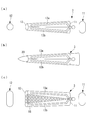
また、本実施形態に係るガイドシース1の第2の変形例として、図17(a)から図17(c)に示すように、通常の状態(先端側開口部12の開口面積が小さい状態)において、先端側開口部12が、基端側開口部11に比べて先細となる形状としてもよい。
また、本実施形態に係るガイドシース1の第2の変形例として、図17(a)から図17(c)に示すように、通常の状態(先端側開口部12の開口面積が小さい状態)において、先端側開口部12が、基端側開口部11に比べて先細となる形状としてもよい。
このようにすることで、図17(b)に示すように、調整機構30により先端側開口部12の開口面積を小さくすることで、ガイドシース本体10を体腔内に挿入する際の作業性を向上することができる。
また、図17(c)に示すように、ガイドシース本体10の側面に、蛇腹等の拡張部18を設けることとしてもよい。このようにすることで、先端側開口部12の開口面積の調整範囲を大きくすることができ、体腔内への挿入時には先端側開口部12を小さくするとともに、挿入部20,21の挿入時には先端側開口部12を拡張してこれら挿入部20,21を所望の間隔にすることができる。
[第3の変形例]
また、本実施形態に係るガイドシース1の第3の変形例として、図18に示すように、 ガイドシース本体10の内側において、挿入部20,21とガイドシース本体10の内壁面との隙間を封止する封止部41を備えることとしてもよい。
また、本実施形態に係るガイドシース1の第3の変形例として、図18に示すように、 ガイドシース本体10の内側において、挿入部20,21とガイドシース本体10の内壁面との隙間を封止する封止部41を備えることとしてもよい。
封止部41は、例えばシリコン樹脂で構成されており、挿入部20,21を挿通させるためのスリット42,43がそれぞれ設けられている。スリット42,43は、挿入部20,21を挿通すると、シリコン樹脂の弾力により挿入部20,21に密着し、気密を保持するようになっている。
このような構成を有することで、封止部41は、体腔内に留置されたガイドシース本体10内に挿入部20,21を挿入した状態において、体腔内の気密を保つことができるようになっている。なお、封止部41は、トロッカー24やダイレータ23を挿入する際には取り外しておき、挿入部20,21を挿入する際にガイドシース本体10の内側に嵌め込む。
本変形例に係るガイドシース4によれば、体腔内に留置されたガイドシース本体10内に挿入部20,21を挿入した状態において、封止部41により体腔内の気密を保つことができる。
[第4の変形例]
また、本実施形態に係るガイドシース1の第4の変形例として、図19(a)から図19(d)に示すように、調整機構30が、先端側開口部12の開口面積を維持するロック機構を備えることとしてもよい。ここで、図19(a)は、本変形例に係る調整機構30の部分拡大図、図19(b)から図19(c)は、図19(a)のロックレバー36の部分拡大図である。
また、本実施形態に係るガイドシース1の第4の変形例として、図19(a)から図19(d)に示すように、調整機構30が、先端側開口部12の開口面積を維持するロック機構を備えることとしてもよい。ここで、図19(a)は、本変形例に係る調整機構30の部分拡大図、図19(b)から図19(c)は、図19(a)のロックレバー36の部分拡大図である。
調整機構30は、骨格部13aに接続されたロックレバー36と、ロックレバー36に形成された突起部37と、骨格部13bに設けられ、突起部37と嵌合する嵌合部38と、ロックレバー36を弾性力によって所定の角度に維持するバネ部39とを備えている。
先端側開口部12の開口面積が最小の状態では、図19(b)に示すように、ロックレバー36に形成された突起部37は、嵌合部38とは嵌合しないようになっている。
この状態において、調整機構30を動作させて、先端側開口部12の開口面積を大きくした場合には、骨格部13aと骨格部13bとが相対移動し、これら骨格部13a,13bに固定された突起部37と嵌合部38とが近接する。
この状態において、調整機構30を動作させて、先端側開口部12の開口面積を大きくした場合には、骨格部13aと骨格部13bとが相対移動し、これら骨格部13a,13bに固定された突起部37と嵌合部38とが近接する。
そして、先端側開口部12の開口面積が最大の状態において、図19(c)に示すように、ロックレバー36に形成された突起部37が、嵌合部38に嵌合するようになっている。これにより、調整機構30がロックされ、先端側開口部12の開口面積が維持される。
この状態から先端側開口部12の開口面積を小さくするには、調整機構30のロックを解除する。この際には、図19(d)に示すように、バネ部39の弾性力に逆らってロックレバー36を傾けて、突起部37の嵌合部38への嵌合を解除する。これにより、調整機構30を動作させて、先端側開口部12の開口面積を小さくすることができる。
本変形例に係るガイドシース5によれば、体腔内にガイドシース本体10を挿入した状態において、先端側開口部12の開口面積が意図せずに変化することを防止することができ、挿入部20,21同士の間隔を維持することができる。
以上、本発明の実施形態および各変形例について図面を参照して詳述してきたが、具体的な構成はこの実施形態に限られるものではなく、本発明の要旨を逸脱しない範囲の設計変更等も含まれる。例えば、本発明を上記の実施形態および変形例を適宜組み合わせた実施形態に適用してもよい。
また、各実施形態において、本発明に係るガイドシースを用いて、心膜腔内に内視鏡の挿入部を挿入する場合を例に挙げて説明したが、本発明はこの例に限定されるものではなく、本発明に係るガイドシースを他の体腔内に挿入することとしてもよい。
また、各実施形態において、ガイドシース内に2本の挿入部を挿入する例について説明したが、3本以上の挿入部を挿入することとしてもよい。
また、各実施形態において、ガイドシース内に2本の挿入部を挿入する例について説明したが、3本以上の挿入部を挿入することとしてもよい。
A 心臓
B 心膜
C 心膜腔内
1,2,3,4,5 ガイドシース
10 ガイドシース本体
10a,10b ガイドシース分割体
11 基端側開口部
12 先端側開口部
13a,13b 骨格部
14a,14b チャンネル分離壁
20,21 挿入部
23 ダイレータ
25,26 ガイドワイヤ
30 調整機構
31 回転支持部
32 回転操作部
33 ピニオン部
34a,34b ラック部
36 ロックレバー
37 突起部
38 嵌合部
39 バネ部
41 封止部
B 心膜
C 心膜腔内
1,2,3,4,5 ガイドシース
10 ガイドシース本体
10a,10b ガイドシース分割体
11 基端側開口部
12 先端側開口部
13a,13b 骨格部
14a,14b チャンネル分離壁
20,21 挿入部
23 ダイレータ
25,26 ガイドワイヤ
30 調整機構
31 回転支持部
32 回転操作部
33 ピニオン部
34a,34b ラック部
36 ロックレバー
37 突起部
38 嵌合部
39 バネ部
41 封止部
Claims (9)
- 体腔内に挿入される医療器具の挿入部を誘導する筒状のガイドシースであって、
該ガイドシースの基端側に設けられ、複数の前記挿入部が導入される基端側開口部と、
前記ガイドシースの先端側に設けられ、複数の前記挿入部が導出される先端側開口部と、
前記先端側開口部の開口面積を調整する調整機構とを備えるガイドシース。 - 半筒部材からそれぞれ構成された一対のガイドシース分割体を備え、
前記調整機構が、
前記一対のガイドシース分割体の基端側に設けられ、前記一対のガイドシース分割体を前記挿入部の挿入方向に直交する軸線回りに相対回転可能に支持する回転支持部と、
該回転支持部を中心として前記一対のガイドシース分割体を相対的に回転させる回転操作部とを備える請求項1記載のガイドシース。 - 前記ガイドシース分割体が、
剛体から構成される骨格部と、
弾性体から構成される分割体本体とを備える請求項2記載のガイドシース。 - 前記ガイドシース分割体が、体腔内の圧力よりも大きな耐変形強度を有する請求項2記載のガイドシース。
- 前記ガイドシースの内側に設けられ、前記ガイドシース内における複数の前記挿入部の位置を規制する規制機構を備える請求項1記載のガイドシース。
- 前記ガイドシースの内側に設けられ、前記挿入部と前記ガイドシース内壁面との隙間を封止する封止部を備える請求項1記載のガイドシース。
- 前記先端側開口部が、前記基端側開口部よりも小さく形成されている請求項1記載のガイドシース。
- 前記調整機構が、ラックアンドピニオン機構を備える請求項1記載のガイドシース。
- 前記調整機構が、前記先端側開口部の開口面積を維持するロック機構を備える請求項1記載のガイドシース。
Applications Claiming Priority (2)
| Application Number | Priority Date | Filing Date | Title |
|---|---|---|---|
| JP2011095191A JP2012223443A (ja) | 2011-04-21 | 2011-04-21 | ガイドシース |
| JP2011-095191 | 2011-04-21 |
Publications (1)
| Publication Number | Publication Date |
|---|---|
| WO2012144348A1 true WO2012144348A1 (ja) | 2012-10-26 |
Family
ID=47041460
Family Applications (1)
| Application Number | Title | Priority Date | Filing Date |
|---|---|---|---|
| PCT/JP2012/059510 Ceased WO2012144348A1 (ja) | 2011-04-21 | 2012-04-06 | ガイドシース |
Country Status (2)
| Country | Link |
|---|---|
| JP (1) | JP2012223443A (ja) |
| WO (1) | WO2012144348A1 (ja) |
Citations (3)
| Publication number | Priority date | Publication date | Assignee | Title |
|---|---|---|---|---|
| JP2005530586A (ja) * | 2002-06-26 | 2005-10-13 | エスディージーアイ・ホールディングス・インコーポレーテッド | 侵襲性を最小にする組織牽引及び外科処置のための器具と方法 |
| JP2009531081A (ja) * | 2006-03-17 | 2009-09-03 | ボエッジ メディカル, インコーポレイテッド | 組織可視化および操作システム |
| JP2010508959A (ja) * | 2006-11-09 | 2010-03-25 | エヌコンタクト サージカル, インコーポレイテッド | 後部外科アクセスのための横隔膜進入 |
-
2011
- 2011-04-21 JP JP2011095191A patent/JP2012223443A/ja active Pending
-
2012
- 2012-04-06 WO PCT/JP2012/059510 patent/WO2012144348A1/ja not_active Ceased
Patent Citations (3)
| Publication number | Priority date | Publication date | Assignee | Title |
|---|---|---|---|---|
| JP2005530586A (ja) * | 2002-06-26 | 2005-10-13 | エスディージーアイ・ホールディングス・インコーポレーテッド | 侵襲性を最小にする組織牽引及び外科処置のための器具と方法 |
| JP2009531081A (ja) * | 2006-03-17 | 2009-09-03 | ボエッジ メディカル, インコーポレイテッド | 組織可視化および操作システム |
| JP2010508959A (ja) * | 2006-11-09 | 2010-03-25 | エヌコンタクト サージカル, インコーポレイテッド | 後部外科アクセスのための横隔膜進入 |
Also Published As
| Publication number | Publication date |
|---|---|
| JP2012223443A (ja) | 2012-11-15 |
Similar Documents
| Publication | Publication Date | Title |
|---|---|---|
| JP5730873B2 (ja) | 偏向可能な処置器具用ポート部 | |
| JP5091229B2 (ja) | 経管腔的外科手術システム | |
| JP6344828B2 (ja) | アクセスデバイスおよび該デバイスを備えたアセンブリ | |
| JP2012518478A (ja) | マルチ処置器具を備えたアクセス装置およびシステム | |
| JP4902017B2 (ja) | 医療用マニピュレータ | |
| US11007347B2 (en) | Deflectable insertion tool | |
| JP2004195037A (ja) | 医療用処置器具の挿入ポート | |
| JP2016540572A5 (ja) | ||
| JP6177021B2 (ja) | 内視鏡 | |
| US20140039387A1 (en) | Guide tube for microsurgical instruments | |
| JP2005046274A (ja) | 内視鏡挿入用補助具 | |
| US10933214B2 (en) | Method for producing a deflectable insertion tool | |
| WO2019030848A1 (ja) | 処置具 | |
| WO2020121438A1 (ja) | 内視鏡用チャンネルユニット、内視鏡 | |
| JP4841821B2 (ja) | 組織に対する手術手技用のアプライヤー | |
| JP2005103277A5 (ja) | ||
| KR101750628B1 (ko) | 내시경 장비에 부착된 수술 팔을 포함하는 수술용 장치 및 이를 포함하는 수술 시스템 | |
| JP2011136175A (ja) | 内視鏡装置 | |
| JP2012223443A (ja) | ガイドシース | |
| JP4344734B2 (ja) | 医療用処理器具の挿入ポート | |
| US9687270B2 (en) | Instrument system for minimally invasive surgery in single port technology | |
| WO2023032145A1 (ja) | 処置装置、処置具操作デバイス、処置システムおよび処置具操作方法 | |
| JP6747800B2 (ja) | 処置具挿通具 | |
| KR102486623B1 (ko) | 최소침습 척추수술을 위한 비원형 확장기 유닛 | |
| KR20210055163A (ko) | 척추 내시경 수술용 확장형 시스 |
Legal Events
| Date | Code | Title | Description |
|---|---|---|---|
| 121 | Ep: the epo has been informed by wipo that ep was designated in this application |
Ref document number: 12773605 Country of ref document: EP Kind code of ref document: A1 |
|
| NENP | Non-entry into the national phase |
Ref country code: DE |
|
| 122 | Ep: pct application non-entry in european phase |
Ref document number: 12773605 Country of ref document: EP Kind code of ref document: A1 |