WO2012144674A1 - Module de batterie amovible, et procédé et appareil d'égalisation des charges d'une chaîne de batteries au moyen dudit module - Google Patents
Module de batterie amovible, et procédé et appareil d'égalisation des charges d'une chaîne de batteries au moyen dudit module Download PDFInfo
- Publication number
- WO2012144674A1 WO2012144674A1 PCT/KR2011/002926 KR2011002926W WO2012144674A1 WO 2012144674 A1 WO2012144674 A1 WO 2012144674A1 KR 2011002926 W KR2011002926 W KR 2011002926W WO 2012144674 A1 WO2012144674 A1 WO 2012144674A1
- Authority
- WO
- WIPO (PCT)
- Prior art keywords
- battery
- charge
- cell
- battery cell
- module
- Prior art date
- Legal status (The legal status is an assumption and is not a legal conclusion. Google has not performed a legal analysis and makes no representation as to the accuracy of the status listed.)
- Ceased
Links
Images


Classifications
-
- H—ELECTRICITY
- H02—GENERATION; CONVERSION OR DISTRIBUTION OF ELECTRIC POWER
- H02J—ELECTRIC POWER NETWORKS; CIRCUIT ARRANGEMENTS OR SYSTEMS FOR SUPPLYING OR DISTRIBUTING ELECTRIC POWER; SYSTEMS FOR STORING ELECTRIC ENERGY
- H02J7/00—Circuit arrangements for charging or discharging batteries or for supplying loads from batteries
- H02J7/50—Circuit arrangements for charging or discharging batteries or for supplying loads from batteries acting upon multiple batteries simultaneously or sequentially
- H02J7/52—Circuit arrangements for charging or discharging batteries or for supplying loads from batteries acting upon multiple batteries simultaneously or sequentially for charge balancing, e.g. equalisation of charge between batteries
-
- H—ELECTRICITY
- H01—ELECTRIC ELEMENTS
- H01M—PROCESSES OR MEANS, e.g. BATTERIES, FOR THE DIRECT CONVERSION OF CHEMICAL ENERGY INTO ELECTRICAL ENERGY
- H01M10/00—Secondary cells; Manufacture thereof
- H01M10/42—Methods or arrangements for servicing or maintenance of secondary cells or secondary half-cells
- H01M10/44—Methods for charging or discharging
- H01M10/441—Methods for charging or discharging for several batteries or cells simultaneously or sequentially
-
- H—ELECTRICITY
- H01—ELECTRIC ELEMENTS
- H01M—PROCESSES OR MEANS, e.g. BATTERIES, FOR THE DIRECT CONVERSION OF CHEMICAL ENERGY INTO ELECTRICAL ENERGY
- H01M10/00—Secondary cells; Manufacture thereof
- H01M10/42—Methods or arrangements for servicing or maintenance of secondary cells or secondary half-cells
- H01M10/48—Accumulators combined with arrangements for measuring, testing or indicating the condition of cells, e.g. the level or density of the electrolyte
- H01M10/482—Accumulators combined with arrangements for measuring, testing or indicating the condition of cells, e.g. the level or density of the electrolyte for several batteries or cells simultaneously or sequentially
-
- H—ELECTRICITY
- H02—GENERATION; CONVERSION OR DISTRIBUTION OF ELECTRIC POWER
- H02J—ELECTRIC POWER NETWORKS; CIRCUIT ARRANGEMENTS OR SYSTEMS FOR SUPPLYING OR DISTRIBUTING ELECTRIC POWER; SYSTEMS FOR STORING ELECTRIC ENERGY
- H02J7/00—Circuit arrangements for charging or discharging batteries or for supplying loads from batteries
- H02J7/50—Circuit arrangements for charging or discharging batteries or for supplying loads from batteries acting upon multiple batteries simultaneously or sequentially
- H02J7/52—Circuit arrangements for charging or discharging batteries or for supplying loads from batteries acting upon multiple batteries simultaneously or sequentially for charge balancing, e.g. equalisation of charge between batteries
- H02J7/56—Active balancing, e.g. using capacitor-based, inductor-based or DC-DC converters
-
- G—PHYSICS
- G01—MEASURING; TESTING
- G01R—MEASURING ELECTRIC VARIABLES; MEASURING MAGNETIC VARIABLES
- G01R19/00—Arrangements for measuring currents or voltages or for indicating presence or sign thereof
- G01R19/165—Indicating that current or voltage is either above or below a predetermined value or within or outside a predetermined range of values
- G01R19/16533—Indicating that current or voltage is either above or below a predetermined value or within or outside a predetermined range of values characterised by the application
- G01R19/16538—Indicating that current or voltage is either above or below a predetermined value or within or outside a predetermined range of values characterised by the application in AC or DC supplies
- G01R19/16542—Indicating that current or voltage is either above or below a predetermined value or within or outside a predetermined range of values characterised by the application in AC or DC supplies for batteries
-
- G—PHYSICS
- G01—MEASURING; TESTING
- G01R—MEASURING ELECTRIC VARIABLES; MEASURING MAGNETIC VARIABLES
- G01R31/00—Arrangements for testing electric properties; Arrangements for locating electric faults; Arrangements for electrical testing characterised by what is being tested not provided for elsewhere
- G01R31/36—Arrangements for testing, measuring or monitoring the electrical condition of accumulators or electric batteries, e.g. capacity or state of charge [SoC]
- G01R31/382—Arrangements for monitoring battery or accumulator variables, e.g. SoC
- G01R31/3835—Arrangements for monitoring battery or accumulator variables, e.g. SoC involving only voltage measurements
-
- G—PHYSICS
- G01—MEASURING; TESTING
- G01R—MEASURING ELECTRIC VARIABLES; MEASURING MAGNETIC VARIABLES
- G01R31/00—Arrangements for testing electric properties; Arrangements for locating electric faults; Arrangements for electrical testing characterised by what is being tested not provided for elsewhere
- G01R31/36—Arrangements for testing, measuring or monitoring the electrical condition of accumulators or electric batteries, e.g. capacity or state of charge [SoC]
- G01R31/396—Acquisition or processing of data for testing or for monitoring individual cells or groups of cells within a battery
-
- H—ELECTRICITY
- H02—GENERATION; CONVERSION OR DISTRIBUTION OF ELECTRIC POWER
- H02J—ELECTRIC POWER NETWORKS; CIRCUIT ARRANGEMENTS OR SYSTEMS FOR SUPPLYING OR DISTRIBUTING ELECTRIC POWER; SYSTEMS FOR STORING ELECTRIC ENERGY
- H02J7/00—Circuit arrangements for charging or discharging batteries or for supplying loads from batteries
- H02J7/80—Circuit arrangements for charging or discharging batteries or for supplying loads from batteries including monitoring or indicating arrangements
- H02J7/82—Control of state of charge [SOC]
-
- H—ELECTRICITY
- H02—GENERATION; CONVERSION OR DISTRIBUTION OF ELECTRIC POWER
- H02J—ELECTRIC POWER NETWORKS; CIRCUIT ARRANGEMENTS OR SYSTEMS FOR SUPPLYING OR DISTRIBUTING ELECTRIC POWER; SYSTEMS FOR STORING ELECTRIC ENERGY
- H02J7/00—Circuit arrangements for charging or discharging batteries or for supplying loads from batteries
- H02J7/80—Circuit arrangements for charging or discharging batteries or for supplying loads from batteries including monitoring or indicating arrangements
- H02J7/84—Control of state of health [SOH]
-
- Y—GENERAL TAGGING OF NEW TECHNOLOGICAL DEVELOPMENTS; GENERAL TAGGING OF CROSS-SECTIONAL TECHNOLOGIES SPANNING OVER SEVERAL SECTIONS OF THE IPC; TECHNICAL SUBJECTS COVERED BY FORMER USPC CROSS-REFERENCE ART COLLECTIONS [XRACs] AND DIGESTS
- Y02—TECHNOLOGIES OR APPLICATIONS FOR MITIGATION OR ADAPTATION AGAINST CLIMATE CHANGE
- Y02E—REDUCTION OF GREENHOUSE GAS [GHG] EMISSIONS, RELATED TO ENERGY GENERATION, TRANSMISSION OR DISTRIBUTION
- Y02E60/00—Enabling technologies; Technologies with a potential or indirect contribution to GHG emissions mitigation
- Y02E60/10—Energy storage using batteries
Definitions
- the present invention relates to a detachable battery module, a method and device for uniformity of charge for a battery string, and more specifically, to achieve cell balancing (also referred to as charge uniformity) with an IC that monitors battery status information in real time.
- charge uniformity methods and apparatus for achieving charge uniformity of multiple battery strings using a uniform device are also referred to as charge uniformity.
- k batteries are divided into M module units and connected in series, and each module has a switch block connected to the right side of the battery. This switch block selects a specific cell to provide the next capacitor and current path.
- the potential stored in the capacitor is then read by the A / D converter and its value is input to the microprocessor.
- the input battery sensing information is used to operate the battery in the microprocessor. If a particular cell is undercharged or overcharged, the microprocessor drives the cell uniformity device connected in parallel to each module to adjust the charge uniformity of the entire battery. It can be achieved.
- the present invention has been proposed to solve the problems according to the prior art addressed above, and does not use individual circuits of increasing complexity to control multiple cells per cell or module, and only one charge uniform converter and battery monitoring. It is an object to provide a reliable and efficient charge uniform apparatus and method by using an IC circuit.
- the present invention in the use of the control switch in the high stack voltage situation of a plurality of batteries, the charge uniformity device to overcome the voltage stress of the control switch used through the modularization of the battery, and to enable the stable use of the battery And to provide a method.
- the removable battery module includes at least one battery cell, a switch block portion for switching the battery cells, a module switch portion for selecting the switch block, a battery cell for monitoring and measuring cell potential to transmit cell potential information. Battery monitoring unit and the like.
- the battery monitoring unit and the switch block unit may be configured as one integrated circuit.
- the switch block unit or the module switch unit may be configured of at least one of a metal oxide semiconductor field effect transistor (MOSFET), a bipolar junction transistor (BJT), and a relay.
- MOSFET metal oxide semiconductor field effect transistor
- BJT bipolar junction transistor
- relay a relay
- a charge uniformity device for a battery string using such a removable battery module.
- the charge uniformity device includes at least one removable battery module, a control unit that receives cell potential information from the detachable battery module, compares the cell potential information with a pre-stored reference value, and determines whether to uniformize the charge of the battery cell; And a homogenization converter for performing charge equalization by charging or discharging the battery cell for a predetermined operation time depending on whether the charge is equalized.
- control unit and the equalizing converter become a master module
- the removable battery module becomes a slave module detachable from the master module.
- the battery monitoring unit controls the removable battery module
- the module switch unit may share the equalization converter for each removable battery module, or insulate between the removable battery modules.
- the homogenizing converter may be a DC / DC converter or an isolation transformer of a charge / dischargeable type
- the switch block portion or the module switch portion may include at least one of a metal oxide semiconductor field effect transistor (MOSFET), a bipolar junction transistor (BJT), and a relay. It can be composed of one.
- MOSFET metal oxide semiconductor field effect transistor
- BJT bipolar junction transistor
- the controller may move the entire battery cell energy to the corresponding battery cell or move the entire battery cell energy to the corresponding battery cell.
- the energy of the external power source may be transferred to the low charged battery cell or the energy of the overcharged battery cell may be transferred to the energy of the external power source.
- Yet another embodiment of the present invention provides a charge uniformity method for a series connected battery string using a removable battery module.
- the method comprises the steps of: monitoring at least one battery cell included in at least one removable battery module to measure cell potential for the battery cell, transmitting measured battery cell potential information, and transmitting the transmitted cell potential Comparing the information with a pre-stored reference value to create a charge equalization cell list for overcharged or uncharged battery cells, connecting a battery module including the corresponding battery cells according to the charge equalization list, and through a equalization converter. Performing charge equalization for the battery cell for a predetermined period;
- the method may include: performing charge equalization on the battery cell, determining whether the battery is equalized with the battery, and as a result of the charge uniformity, when the telephone uniformity is completed, The method may further include measuring the cell potential for the cell.
- the reference value may be any one of a state of charge (SOC), a user specified voltage, a battery pack or an average voltage of the battery cell, a user specified voltage and a state of health (SOH) increased or decreased to a battery pack or an average voltage.
- SOC state of charge
- SOH state of health
- the determining of the charge uniformity for the corresponding battery cell may include comparing the average value of the battery cells of the entire detachable battery module, the average value of the battery cells in one of the removable battery modules, or the preset value. It can be a step to judge.
- the method may include moving the battery cell total energy to the battery cell or moving the battery cell total energy to the battery cell if the battery cell is low or overcharged relative to other battery cells. If only the battery cell is low or overcharged, the method may further include moving energy of the external power source to the low charged battery cell or moving energy of the overcharged battery cell to the energy of the external power source.
- the predetermined operation time is a value calculated through mathematical modeling according to the charge or discharge current amount of the equalization means and the energy storage capacity of the corresponding battery cell, a value stored in advance, or periodically for a predetermined time period in the corresponding battery cell.
- the cell voltage, SOC, and SOH measurements may be used to determine a user's desired value or a value that is programmed and stored in advance (reference value).
- the present invention it is possible to reduce the complexity, cost and volume of the entire battery operation system by using the charge uniformity device and the battery monitoring IC in one module and by using specific functions of the monitoring IC in the charge uniformity device.
- the charge uniformity device easily adjusts the charge uniform current amount by using a single direct current (DC) -DC converter in common, and uses a reliable monitoring IC in real time regardless of the charge uniformity circuit.
- Cell information may be processed in a central processing unit (ie, a control unit).
- the charge uniformity device is divided into a master unit and a slave unit and modularized so that expansion and contraction are possible regardless of the number of batteries, and circuits are separated for each module. It is easy to construct a circuit and can effectively cope by replacing only a damaged module when a circuit is damaged.
- another effect of the present invention is that when the charge uniformity device uses a DC-DC converter, the entire battery cell is divided by a predetermined number and driven by a module, thereby reducing the voltage stress of the switch used in the switch block, and the charge uniformity.
- the driving algorithm of the device is determined by a user or by a program calculation and may be variable by communication between the central processing unit (ie, the controller) and the module.
- Another effect of the present invention is to combine the entire battery cells into a certain k battery modules, thereby having a low voltage bidirectional control switch having only k battery voltages with a breakdown voltage instead of a bidirectional control switch having a total voltage of the battery It is possible to fully control the charge charge of the battery cell.
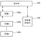
- FIG. 1 is a conceptual diagram for implementing a charge uniformity device according to an embodiment of the present invention.
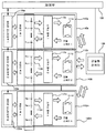
- FIG. 2 is a circuit block diagram implementing the concept of FIG. 1.
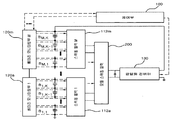
- FIG. 3 is an overall configuration diagram of a charge uniformity device according to an embodiment of the present invention.
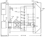
- FIG. 4 is a diagram illustrating the circuit operation of the charge uniform device for the second cell of the second module in FIG. 2.
- FIG. 5 is a circuit diagram showing an example of the device configuration of the charge uniform device according to an embodiment of the present invention.
- FIG. 6 is a flowchart illustrating an operation sequence of a charge uniform circuit according to an embodiment of the present invention.
- control unit 110a to 110n module switch unit
- module switch 112a to 112n switch block
- Battery pack 120a to 120n battery monitoring unit
- a charge uniformity device includes a detachable battery module (140a to 140m), a control unit (100) for controlling the detachable battery module, and the battery module (140a to 140m) according to a command of the control unit. ), And the equalization converter 130 for uniformizing the charge.
- the battery modules 140a to 140m are in a detachable form and include a battery cell, a battery monitoring IC for monitoring the state of the battery cell, and a switch for switching the module. A diagram illustrating this is shown in FIG. 2. This will be described later with reference to FIG. 2.
- the controller 100 may be a microprocessor, a microcomputer, or the like, and an algorithm for performing a balancing (ie, charge equalization) operation of a battery cell according to an embodiment of the present invention is programmed.
- a memory may be configured in the controller 100, which may use an internal memory of the controller 100 or a separate memory.
- nonvolatile memory such as electrically erasable programmable read-only memory (EEPROM), static RAM (SRAM), ferro-electric RAM (FRAM), phase-change RAM (PRAM), and magnetic RAM (MRAM). Can be used.
- EEPROM electrically erasable programmable read-only memory
- SRAM static RAM
- FRAM ferro-electric RAM
- PRAM phase-change RAM
- MRAM magnetic RAM
- the equalization converter 130 performs a function of executing charge equalization of the battery modules 140a to 140m such that at least one cell balancing (charge equalization) of the battery modules 140a to 140m is performed according to a command of the controller 100. do. Therefore, the homogenizing converter 130 may be a DC-DC converter of the type capable of charge discharge.
- FIG. 2 is a circuit block diagram implementing the concept of FIG. 1.
- the configuration of the battery module 140a among the removable battery modules 140a through 140m includes a battery pack 113a including battery cells B 1, 1 through B 1, k , and the battery pack ( battery cell (B 1,1 to B 1, k) the battery cell (B 1,1 to B 1, k) in the monitoring unit (120a), and a battery pack (113a) for monitoring the state of the inside 113a) the The switch block 112a for switching, the module switch unit 111a for selecting the switch block 112a, and switching to charge or discharge the corresponding battery cell.
- These removable battery modules 140a are arranged in a number of units 140a to 140m in a uniform device. These components are described as follows.
- the battery packs 113a to 113n have a plurality of battery cells B 1,1 to B M, k connected in series, and the plurality of battery cells are any number of batteries (usually eight), but one of the present invention The embodiment is not limited thereto.
- the battery cells B 1,1 to B 1, k are illustrated as being configured in series in the battery pack 113a, the battery cells B 1,1 to B 1, k may be configured in parallel.
- the battery cell may be a hybrid battery such as a nickel metal battery or a lithium ion battery.
- the battery monitoring units 120a to 120b may be configured using a commercially available battery dedicated IC.
- the battery monitoring unit transmits the state information of the battery cells (for example, B 1,1 to B 1, k ) to the control unit 100, and battery protection and cell balancing (charge equalization) according to the command of the control unit. Involved in control).
- the switch block units 112a to 112n are responsible for connecting the specific battery cells that are low or overcharged with the equalization converter 130 in the charge equalization process.
- the module switch units 111a through 111n exist in each battery module 140a through 140n in addition to the cell switch block units 113a through 113m connected to the cells, thereby sharing the equalization converter 130 for each module.
- the module switch unit serves to isolate the battery modules 140a to 140m and serves to separate the battery modules into individual modules.
- information such as voltage information and temperature of the battery cells B 1 , 1 to B M, k is collected and controlled by the battery monitoring unit 120a to 120m, and the control unit 100.
- the battery monitoring unit Through the communication of the battery monitoring unit (120a to 120m), the battery monitoring unit is also responsible for part of the control of the equalization converter (130).
- the operation of the equalization converter 130 for charge uniformity is controlled according to an algorithm determined through the battery cell sensing information of the controller 100. A diagram illustrating this algorithm is shown in FIG. 6. This will be described later.
- FIG. 3 is an overall configuration diagram of a charge uniformity device according to an embodiment of the present invention. That is, FIG. 3 shows an example of a charge uniform device using one equalization converter 130, battery monitoring units 120a to 120m and control switches 112a to 112m and 200.
- the controller 100 is responsible for system control based on the information of all the battery cells B 1 , 1 to B M, K , and one equalization converter 130 generating the cell charge equalization energy is controlled. Under the control of 100 is connected to the module switch unit 200.
- a bidirectional DC-DC converter capable of charging / discharging may be used as the equalizing converter 130.
- One module switch unit 200 existing for each battery module is shared by the bidirectional cell selection switches 112a to 112m connected to the respective battery cells B 1 , 1 to B M, K , and the cells for selecting the cells.
- the switch blocks 112a to 112m are controlled by the control signals of the battery monitoring units 120a to 120m.
- the battery monitoring units 120a to 120m positioned for each battery module are directly connected to each of the battery cells B 1 , 1 to B M, K , so that battery cell status information (for example, SOC, SOH, current, and voltage) may be provided. And the like).
- the battery monitoring units 120a to 120m collect state information of each of the battery cells B 1 , 1 to B M and K and transmit the information to the control unit 100 which is a central processing unit in accordance with the data communication protocol. That is, as described above, the battery monitoring unit 120a may store state information (for example, SOC, SOH, voltage, current, etc.) of each battery cell of the battery cells B 1, 1 to B 1, K. The battery monitoring unit 120m collects state information of each battery cell of the battery cells BM , 1 to BM, K.
- state information for example, SOC, SOH, voltage, current, etc.
- the controller 100 determines whether the specific battery cells are uniform in charge by a predetermined algorithm, and sends control signals to the battery monitoring units 120a to 120m of each battery module 140a to 140m of FIG. 2. As such, the control unit 100 and the battery monitoring units 120a to 120m are connected to each other to exchange information. That is, as shown in FIG. 3, the communication lines which are dotted lines are connected. Therefore, even if one battery module (140a to 140m of FIG. 2) is removed by abnormal operation, the remaining battery module can still communicate with the controller 100.
- the battery monitoring units 120a to 120m may be directly connected to each battery cell to obtain real time battery information.
- the battery monitoring unit 120a to 120m may generate a specific control signal by receiving a command from the controller 100.
- the control switches 112a to 112m and 200 connected to the battery monitoring units 120a to 120m receive the control signals inside the battery monitoring units 120a to 120m and select the corresponding battery cells B M, 1 to B M, K.
- the switching block portions 112a to 112m are turned on and off, and this operation generates a cell charge equalization current path for a specific cell.
- the battery monitoring units 120a to 120m control ON and OFF operations of the module switch unit 111a to 111m of the corresponding battery module 140a to 140m of FIG. 2. Such control may vary depending on the number of output pins of the battery monitoring units 120a to 120m, and may be configured to control the module switch unit 111a to 111m of FIG. 2 directly from the controller 100.
- FIG. 4 is a diagram illustrating the circuit operation of the charge uniform device for the second cell of the second module in FIG. 2.
- a battery stack monitor product name "LTC6802", Linear Technology Co., Ltd.
- LTC6802 Linear Technology Co., Ltd.
- the “LTC6802” is directly connected to each battery cell to measure the potential of the battery cell and the temperature of the battery cell, as well as a switch for controlling the battery cell therein.
- FIG. 4 illustrates a case where "LTC6802" is applied to understand an embodiment of the present invention, and may be applied to any electronic component having the above-described function.
- the commonly used DC-DC converter 130 operates through the total voltage or the external voltage of the battery cells B 2, 1 to B 2, K , and is controlled in both directions or unidirectionally. . Therefore, the DC-DC converter 130 is responsible for charging or discharging specific battery cells B 2, 1 to B 2, K. In addition, the DC-DC converter 130 is not shown as a part for controlling an operation of a pulse width modulation (PWM) signal of the controller 100 or a controller (DC-DC converter 130) controlled by the controller 100. ) Receives the PWM signal.
- PWM pulse width modulation
- the low voltage bidirectional control switches 111b and 112b that control the charging and discharging currents of the battery cells B 2, 1 to B 2, K in the battery pack 113b are turned on and off by the battery monitoring unit 120b. It works by receiving. At this time, a simple circuit (O 2 , 2 , S 2 , 2 ) for receiving the ON and OFF signals of the battery monitoring unit 120b to the input of each bidirectional control switch (111b, 112b) to make the switch ON, OFF operation Etc.) are connected.
- the circuit uses the voltage of the battery cells B 2, 1 to B 2, K as a power supply device, and requires high ON / OFF switch operation.
- an embodiment of the present invention may be structurally composed of two units.
- the control unit 100 and the DC-DC converter 130 which are central processing units, become one master module, and the control switches 111b and 112b and the battery monitoring unit 120b become slave modules.
- the master unit controls the slave module with overall battery and system status information to generate charge / discharge energy for cell charge uniformity.
- the slave module reads the battery cell information connected to the module and is responsible for switch control for charge uniformization of a specific battery cell.
- FIG. 4 shows a circuit connecting a low voltage bidirectional control switch for each battery module (140a to 140m in FIG. 2) and performing individual charge uniformity using one common DC-DC converter 130.
- FIG. 4 is an example in which a part of a sensing circuit that has been complicated to sense cell voltage information of a plurality of cells B 2, 1 to B 2, K is simply implemented using an integrated monitoring IC device. Shows.
- Figure 4 shows an example in which a battery stack monitor (product name "LTC6802", Linear Technology) is applied, but one embodiment of the present invention is not limited thereto.
- the battery cell to be charged is determined (assuming, for example, one of the battery cells B 2, 1 to B 2, K in the battery module 140b corresponds to FIG. 4), and the bidirectional corresponding thereto. Assume that the control switch 112b is turned on and the relay switch 116b to be the module switch of the battery module 140b to which the battery cell to be charged belongs is turned on. In this case, the bidirectional DC-DC converter 130 which is in common operates under the control of the controller 100.
- the operation of the DC-DC may be operated according to a charging or discharging situation, and in the unidirectional direction, the operation may be performed by a predetermined direction.
- the operation of the DC-DC converter used may vary depending on the type of converter used.
- the control method may vary according to a switched-mode power supply (SMPS) receiving a PWM control signal and a case of receiving a bipolar junction transistor (BJT) or other switch operation.
- SMPS switched-mode power supply
- BJT bipolar junction transistor
- the amount of charge uniform charging and discharging current can be easily and efficiently generated according to the capacity of the battery cell, and the use of the battery monitoring unit 120b This reduces the cost and reduces the volume of the charge homogenizer.
- the above-described DC-DC converter 130 may be composed of a combination of various existing DC-DC converters or linear regulators. At this time, each converter or regulator includes a switch means that the output direction can operate in both directions or unidirectional.
- Such switch means may be composed of a combination of electrically insulated switches such as mechanical switches as well as mechanical switches. A diagram illustrating this is shown in FIG. 5.
- FIG. 5 is a circuit diagram showing an example of the device configuration of the charge uniform device according to an embodiment of the present invention.
- a flyback type bidirectional DC-DC converter 130 may be used as a DC-DC converter, and a switch means may be a metal oxide semiconductor field effect transistor (MOSFET).
- MOSFET metal oxide semiconductor field effect transistor
- FIG. 5 shows only an example in which the charge uniformity device shown in FIG. 1 is implemented using other circuit elements, and it will be understood that the DC-DC converter and the switch may be configured by a combination of other devices. .
- the charge uniformity device proposed in one embodiment of the present invention is performed when the battery potential of each of the series-connected batteries is different from each other in a situation where an electrical charging device or an electrical load is not connected to the series-connected battery.
- an electrical charging device or an electrical load is not connected to the series-connected battery.
- the current carrying capacity of the proposed charge homogeneous device is large or the magnitude of the charged or discharged current is small, it is performed even in the situation where the electric charging device or the electric load is connected. Can be.
- the charge uniformity device proposed in one embodiment of the present invention starts operation when the potentials of the battery cells are different from each other, and the start of the charge uniformity device is performed by measuring the battery cell voltage inputted to the controller 100 and the SOC (by the battery cell voltage). It is determined according to an algorithm programmed in advance in the control unit 100 of FIG. 1 based on a state of charge value or a stage of health (SOH).
- SOH stage of health
- FIG. 6 is a flowchart illustrating a charge uniform operation sequence according to an embodiment of the present invention.
- the battery monitoring unit 120a to 120m of FIG. 2 may operate in the battery cells B 1 and 1 to each of the battery modules 140a to 140m.
- the cell potentials of B M and K are sensed in real time (steps S600 and S610).
- the sensed cell potential value (ie, voltage value) of the battery cells B 1 , 1 to B M, K is measured through the communication line between the battery monitoring units 120a to 120m and the control unit 100. To 120 m).
- a transmission may be performed in real time or at regular time periods. Therefore, the controller 100 determines whether such transmission is completed (step S620).
- the control unit 100 may compare the battery cells exceeding the reference value with respect to the battery balancing target voltages of all the batteries, and the battery cells below the reference value.
- a list is generated (step S630).
- step S620 determines whether the transfer of the potential value of the battery cell is not completed.
- the controller 100 When the battery cell to be charged or discharged is determined by the cell list, the controller 100 first converts the at least one corresponding battery module 140a to 140m from the module switch unit 110a to 110m in FIG. ). Of course , the battery monitoring unit 140a to 140m connects the corresponding battery module and the equalization converter. When the corresponding battery module (which may be singular or plural) is connected to the equalization converter 130, the battery monitoring unit 140a to 140m causes the switch block 112a to cause the corresponding battery cell B 1, 1 to B M. , K ) (step S640).
- the battery monitoring unit 120a to 120m of the corresponding battery module 140a to 140m operates.
- the battery monitoring units 120a to 120m preferentially operate the switches to the bidirectional control switches 111a to 111m through internal switches. Subsequently, a control signal for operating the module switch units 112a to 112m related to the battery module including the battery cell is transmitted.
- the common equalization converter 130 in particular, the DC-DC converter
- the equalization converter 130 charges the battery cell or discharges the charge from the battery cell to perform charge uniformity (steps S650 and S660).
- the equalization converter 130 proceeds with the charge uniformity operation in order from the most preferred battery cell.
- the energy of the external power source is transferred to the low-charged battery cell to increase the potential of the low-charged battery cell.
- the potential of the overcharged battery cell can be lowered by moving the overcharged battery energy to an external power source.
- charge equalization time for such a telephone uniformity
- charge equalization time for various methods for determining such predetermined operating time. This is described as follows.
- Iii A method of determining charge equalization time through mathematical modeling according to the charge or discharge current amount of the converter 130 and the energy storage capacity of the battery cell.
- the charge equalization time is determined by the charge equalization time thus obtained, and the equalization converter can be turned ON and OFF in accordance with the operation time.
- Ii A method using a value previously stored in the control unit 100. Therefore, when the specific battery cell reaches a predetermined cell voltage value through the equalization converter 130 through the relationship table between the state of charge (SOC) value and the voltage of the corresponding battery cell, the equalization converter is turned off.
- SOC state of charge
- a value of the battery cell stored in advance can be changed by the user.
- a value of a specific cell may be an average value of all batteries, an SOC average of all batteries, or a specific value that is increased or decreased to a fixed value in the average of all batteries or SOC.
- the device instead of driving the device through a predetermined charge equalization time, the device performs a charge equalization operation for a certain period of time on a specific battery cell periodically, and then selects a value or programmed by the user through cell voltage, SOC, or SOH measurement. It is a method of comparing with the stored reference value.
- This reference value may be any one of a user-specified voltage, a battery pack or an average voltage, a user-specified voltage increased or decreased by a battery pack or an average voltage, and a state of health (SOH).
- the reference value of the specific cell may be determined by the method described above.
- control unit 100 of FIG. 2 determines whether the charge uniformization is completed (step S670).
- the battery monitoring units 120a to 120m re-measure the potential for the battery cells so that the potential of the battery cells is a reference value. It is determined whether it has reached (step S680).
- step S670 if charge uniformity for the corresponding battery cells B 1 , 1 to B M, K is not completed, steps S630 to S670 are performed again.
- step S680 if the potential of the re-measured battery cell reaches the reference value, the charge uniformization process ends.
Landscapes
- Engineering & Computer Science (AREA)
- Manufacturing & Machinery (AREA)
- Chemical & Material Sciences (AREA)
- Chemical Kinetics & Catalysis (AREA)
- Electrochemistry (AREA)
- General Chemical & Material Sciences (AREA)
- Power Engineering (AREA)
- Charge And Discharge Circuits For Batteries Or The Like (AREA)
- Secondary Cells (AREA)
Abstract
L'invention concerne un module de batterie amovible, et un procédé et un appareil d'égalisation des charges de chaîne de batteries au moyen dudit module. Selon un mode de réalisation de l'invention, l'appareil d'égalisation des charges comprend : au moins un module de batterie amovible; une unité de commande recevant des informations relatives au potentiel d'un élément provenant du module de batterie amovible pour déterminer si les charges associées à un élément de batterie sont égalisées par comparaison des informations relatives au potentiel d'élément avec une valeur standard préalablement stockée; un convertisseur d'égalisation exécutant l'égalisation des charges par charge ou décharge de l'élément de batterie pendant une durée de fonctionnement fixe en fonction de l'égalisation des charges de l'unité de commande; etc. Selon l'invention, une unité maître et une unité asservie étant séparées de façon à modulariser le dispositif d'égalisation des charges, l'augmentation et la diminution sont possibles indépendamment du nombre de batteries, et le circuit étant séparé par des modules, sa conception est facilitée et une réponse efficace est possible par remplacement du seul module endommagé lorsque un circuit est endommagé.
Priority Applications (3)
| Application Number | Priority Date | Filing Date | Title |
|---|---|---|---|
| PCT/KR2011/002926 WO2012144674A1 (fr) | 2011-04-22 | 2011-04-22 | Module de batterie amovible, et procédé et appareil d'égalisation des charges d'une chaîne de batteries au moyen dudit module |
| US14/113,257 US20140042974A1 (en) | 2011-04-22 | 2011-04-22 | Detachable battery module, and method and apparatus for the charge equalization of a battery string using same |
| US15/495,592 US10680447B2 (en) | 2011-04-22 | 2017-04-24 | Charge equalization apparatus for a battery string |
Applications Claiming Priority (1)
| Application Number | Priority Date | Filing Date | Title |
|---|---|---|---|
| PCT/KR2011/002926 WO2012144674A1 (fr) | 2011-04-22 | 2011-04-22 | Module de batterie amovible, et procédé et appareil d'égalisation des charges d'une chaîne de batteries au moyen dudit module |
Related Child Applications (2)
| Application Number | Title | Priority Date | Filing Date |
|---|---|---|---|
| US14/113,257 A-371-Of-International US20140042974A1 (en) | 2011-04-22 | 2011-04-22 | Detachable battery module, and method and apparatus for the charge equalization of a battery string using same |
| US15/495,592 Division US10680447B2 (en) | 2011-04-22 | 2017-04-24 | Charge equalization apparatus for a battery string |
Publications (1)
| Publication Number | Publication Date |
|---|---|
| WO2012144674A1 true WO2012144674A1 (fr) | 2012-10-26 |
Family
ID=47041757
Family Applications (1)
| Application Number | Title | Priority Date | Filing Date |
|---|---|---|---|
| PCT/KR2011/002926 Ceased WO2012144674A1 (fr) | 2011-04-22 | 2011-04-22 | Module de batterie amovible, et procédé et appareil d'égalisation des charges d'une chaîne de batteries au moyen dudit module |
Country Status (2)
| Country | Link |
|---|---|
| US (2) | US20140042974A1 (fr) |
| WO (1) | WO2012144674A1 (fr) |
Cited By (4)
| Publication number | Priority date | Publication date | Assignee | Title |
|---|---|---|---|---|
| CN105024420A (zh) * | 2014-04-28 | 2015-11-04 | 三星电子株式会社 | 电池控制设备、电池包和电池控制方法 |
| CN112526380A (zh) * | 2020-11-19 | 2021-03-19 | 许继集团有限公司 | 一种电池管理单元均衡效率测试方法及系统 |
| CN114763116A (zh) * | 2021-01-13 | 2022-07-19 | 英飞凌科技股份有限公司 | 用于电池管理电路的供电电路 |
| CN115485952A (zh) * | 2020-05-21 | 2022-12-16 | 美光科技公司 | 可穿戴装置的使用中充电 |
Families Citing this family (38)
| Publication number | Priority date | Publication date | Assignee | Title |
|---|---|---|---|---|
| JP5502918B2 (ja) * | 2011-10-13 | 2014-05-28 | 株式会社日本自動車部品総合研究所 | 組電池の充放電装置 |
| US9318910B2 (en) * | 2012-09-06 | 2016-04-19 | Samsung Sdi Co., Ltd. | Cell balancing circuit and cell balancing method using the same |
| JP6428107B2 (ja) * | 2014-09-29 | 2018-11-28 | 株式会社村田製作所 | 蓄電装置、電子機器、電動車両および電力システム |
| US10547184B2 (en) * | 2015-02-18 | 2020-01-28 | The Boeing Company | System and method for battery management |
| EP3349296A4 (fr) * | 2015-09-08 | 2019-05-01 | Kabushiki Kaisha Toshiba | Dispositif de batterie de stockage,procédé, système de batterie de stockage et programme |
| KR102516355B1 (ko) * | 2015-12-21 | 2023-03-31 | 삼성전자주식회사 | 배터리 제어 방법, 배터리 제어 장치, 및 배터리 팩 |
| US10330739B2 (en) | 2016-08-24 | 2019-06-25 | The Boeing Company | Detecting internal short circuits in batteries |
| JP6883396B2 (ja) * | 2016-08-25 | 2021-06-09 | 矢崎総業株式会社 | 急速充電装置 |
| KR102559200B1 (ko) * | 2016-10-05 | 2023-07-25 | 삼성전자주식회사 | 배터리 유닛을 관리하는 장치, 방법, 및 시스템 |
| US10848098B2 (en) | 2016-12-11 | 2020-11-24 | Sandeep Agarwal | Smart energy storage system |
| CN110915093B (zh) * | 2017-01-25 | 2024-05-24 | 麦斯韦尔技术股份有限公司 | 用于电容器模块平衡和保持的系统和方法 |
| JP6855914B2 (ja) | 2017-05-10 | 2021-04-07 | 株式会社デンソー | 制御モジュール |
| JP6946725B2 (ja) * | 2017-05-10 | 2021-10-06 | 株式会社デンソー | 制御モジュール |
| CN107069940A (zh) * | 2017-05-18 | 2017-08-18 | 深圳市云充吧科技有限公司 | 一种可控输出供电设备 |
| KR102150147B1 (ko) * | 2017-05-24 | 2020-09-01 | 주식회사 엘지화학 | 배터리 모듈 균등화 장치 및 방법 |
| CN107231028A (zh) * | 2017-07-31 | 2017-10-03 | 福州福光电子有限公司 | 双向dc‑dc锂电池模组多通道均衡充放电维护装置 |
| JP6928347B2 (ja) * | 2017-08-02 | 2021-09-01 | NExT−e Solutions株式会社 | 管理装置、蓄電装置、蓄電システム、及び、電気機器 |
| KR102202613B1 (ko) * | 2017-09-27 | 2021-01-12 | 주식회사 엘지화학 | 배터리 모듈 균등화 장치, 이를 포함하는 배터리 팩 및 자동차 |
| US10444295B2 (en) * | 2017-12-20 | 2019-10-15 | National Chung Shan Institute Of Science And Technology | Battery balance management circuit |
| CN111196178A (zh) * | 2018-11-16 | 2020-05-26 | 宁德时代新能源科技股份有限公司 | 转换电路、电池均衡系统及电池管理系统 |
| EP3657571A1 (fr) * | 2018-11-26 | 2020-05-27 | Aptiv Technologies Limited | Module de batterie |
| CN110601296A (zh) * | 2019-09-19 | 2019-12-20 | 江西恒动新能源有限公司 | 一种电池管理系统主动均衡电路 |
| US11404885B1 (en) | 2021-02-24 | 2022-08-02 | Inventus Power, Inc. | Large-format battery management systems with gateway PCBA |
| US11489343B2 (en) | 2020-06-02 | 2022-11-01 | Inventus Power, Inc. | Hardware short circuit protection in a large battery pack |
| US12224603B2 (en) | 2020-06-02 | 2025-02-11 | Inventus Power, Inc. | Mode-based disabling of communication bus of a battery management system |
| US11552479B2 (en) | 2020-06-02 | 2023-01-10 | Inventus Power, Inc. | Battery charge balancing circuit for series connections |
| US12301031B1 (en) | 2020-06-02 | 2025-05-13 | Inventus Power, Inc. | Large-format battery management systems with gateway PCBA |
| US11411407B1 (en) | 2021-02-24 | 2022-08-09 | Inventus Power, Inc. | Large-format battery management systems with gateway PCBA |
| US11476677B2 (en) | 2020-06-02 | 2022-10-18 | Inventus Power, Inc. | Battery pack charge cell balancing |
| US11245268B1 (en) | 2020-07-24 | 2022-02-08 | Inventus Power, Inc. | Mode-based disabling of communiction bus of a battery management system |
| US11594892B2 (en) | 2020-06-02 | 2023-02-28 | Inventus Power, Inc. | Battery pack with series or parallel identification signal |
| WO2021243550A1 (fr) | 2020-06-02 | 2021-12-09 | Inventus Power, Inc. | Système de gestion de batterie grand format |
| US11588334B2 (en) | 2020-06-02 | 2023-02-21 | Inventus Power, Inc. | Broadcast of discharge current based on state-of-health imbalance between battery packs |
| US11509144B2 (en) | 2020-06-02 | 2022-11-22 | Inventus Power, Inc. | Large-format battery management system with in-rush current protection for master-slave battery packs |
| CN115836456A (zh) * | 2021-03-10 | 2023-03-21 | 华为数字能源技术有限公司 | 分布式供电系统和控制方法 |
| CN113489080B (zh) * | 2021-05-31 | 2023-05-30 | 南方电网调峰调频发电有限公司 | 电池电量均衡方法、装置、设备及存储介质 |
| CN113394852A (zh) * | 2021-07-16 | 2021-09-14 | 阳光电源股份有限公司 | 一种均衡控制方法及储能系统 |
| CN113696786B (zh) * | 2021-08-23 | 2023-05-23 | 深圳市道通科技股份有限公司 | 电池均衡方法及系统 |
Citations (3)
| Publication number | Priority date | Publication date | Assignee | Title |
|---|---|---|---|---|
| JP2008538408A (ja) * | 2005-04-05 | 2008-10-23 | エナジーシーエス | マルチプレクサ及びスイッチベース電気化学セルの監視及び管理システム並びに方法 |
| JP2010104222A (ja) * | 2008-10-21 | 2010-05-06 | Kazumasa Sakakibara | 電池パックシステム |
| JP2011501640A (ja) * | 2007-10-16 | 2011-01-06 | エスケー エナジー カンパニー リミテッド | 電圧センサーと均等充電装置とが結合されたバッテリー管理 |
Family Cites Families (97)
| Publication number | Priority date | Publication date | Assignee | Title |
|---|---|---|---|---|
| GB834022A (en) * | 1956-07-23 | 1960-05-04 | Harold Martin Harmer | Improvements relating to the charging of secondary batteries |
| DE3326729A1 (de) * | 1983-07-25 | 1985-02-07 | Siemens AG, 1000 Berlin und 8000 München | Verfahren zum betrieb eines elektrochemischen speichers |
| JPH03207226A (ja) * | 1989-12-29 | 1991-09-10 | Toshiba Corp | 電池切換方式 |
| US5153496A (en) * | 1990-09-27 | 1992-10-06 | Baxtrer International Inc. | Cell monitor and control unit for multicell battery |
| DE4132229C2 (de) * | 1991-09-27 | 1994-02-24 | Mentzer Electronic Gmbh | Mikrocontroller-gesteuerte Einrichtung zur Analyse des Ladezustands einer mehrzeiligen Batterie |
| EP0589287A3 (fr) * | 1992-09-22 | 1995-02-01 | Mentzer Electronic Gmbh | Procédé pour le chargement d'une batterie multicellulaire. |
| US5498950A (en) * | 1994-04-29 | 1996-03-12 | Delco Electronics Corp. | Battery monitoring, charging and balancing apparatus |
| JPH07336905A (ja) * | 1994-06-08 | 1995-12-22 | Nissan Motor Co Ltd | 組電池の充電装置 |
| CA2169706A1 (fr) * | 1995-03-03 | 1996-09-04 | Troy Lynn Stockstad | Circuit de commande de charge d'une batterie d'accumulateurs, et methode connexe |
| US5710504A (en) * | 1996-05-20 | 1998-01-20 | The Board Of Trustees Of The University Of Illinois | Switched capacitor system for automatic battery equalization |
| US5914606A (en) * | 1996-10-10 | 1999-06-22 | Becker-Irvin; Craig H. | Battery cell voltage monitor and method |
| US5920179A (en) * | 1997-05-05 | 1999-07-06 | Aer Energy Resources, Inc. | System and method for balancing charge cycles for batteries or multiple-cell battery packs |
| JP3503414B2 (ja) * | 1997-05-12 | 2004-03-08 | 日産自動車株式会社 | 組電池の単電池間充電率調整装置 |
| US5821734A (en) * | 1997-08-29 | 1998-10-13 | Compaq Computer Corporation | Converting battery module with resistor programmation of default output voltage |
| AU1271599A (en) * | 1997-10-20 | 1999-05-10 | Usar Systems Inc. | Improved voltaic pile with charge equalizing system |
| EP1032964A2 (fr) * | 1997-11-17 | 2000-09-06 | Lifestyle Technologies | Systeme d'alimentation polyvalent |
| JP3503453B2 (ja) * | 1997-12-26 | 2004-03-08 | 株式会社日立製作所 | 電池システム及びそれを用いた電気自動車 |
| TW472426B (en) * | 1998-10-06 | 2002-01-11 | Hitachi Ltd | Battery apparatus and control system therefor |
| US6291972B1 (en) * | 1999-02-17 | 2001-09-18 | Chaojiong Zhang | System for battery formation, charging, discharging, and equalization |
| TW492021B (en) * | 1999-11-05 | 2002-06-21 | Tokin Corp | Electrical energy storage provided with cell energy adjusting device and adjust method of cell energy |
| US6583602B2 (en) * | 2001-05-11 | 2003-06-24 | Denso Corporation | Vehicular power supply apparatus and method of controlling the same |
| JP2005521363A (ja) * | 2001-05-25 | 2005-07-14 | ディヴィソン ゲイリー エイチ | 複数のエネルギー貯蔵装置におけるエネルギーを管理する方法及び装置 |
| US7064521B2 (en) * | 2001-08-17 | 2006-06-20 | O2Micro International Limited | Charging circuit for parallel charging in multiple battery systems |
| US7378818B2 (en) * | 2002-11-25 | 2008-05-27 | Tiax Llc | Bidirectional power converter for balancing state of charge among series connected electrical energy storage units |
| US7135836B2 (en) * | 2003-03-28 | 2006-11-14 | Power Designers, Llc | Modular and reconfigurable rapid battery charger |
| TWI260807B (en) * | 2003-12-31 | 2006-08-21 | Ind Tech Res Inst | Equalizer for series of connected battery strings |
| JP4092580B2 (ja) * | 2004-04-30 | 2008-05-28 | 新神戸電機株式会社 | 多直列電池制御システム |
| US20060097700A1 (en) * | 2004-11-10 | 2006-05-11 | Eaglepicher Technologies, Llc | Method and system for cell equalization with charging sources and shunt regulators |
| US7928691B2 (en) * | 2004-11-10 | 2011-04-19 | EaglePicher Technologies | Method and system for cell equalization with isolated charging sources |
| JP4186916B2 (ja) * | 2004-11-18 | 2008-11-26 | 株式会社デンソー | 組電池管理装置 |
| CN101944757B (zh) * | 2004-12-24 | 2012-07-04 | Lg化学株式会社 | 用于在具有多个锂离子电池的电池组中控制电压平衡的系统 |
| CN101088203B (zh) * | 2004-12-24 | 2010-08-18 | Lg化学株式会社 | 用于在具有多个锂离子电池的电池组中控制电压平衡的系统及其方法 |
| EP1842275A4 (fr) * | 2005-01-25 | 2016-05-11 | Victhom Human Bionics Inc | Procede et dispositif de charge de bloc d'alimentation |
| JP2006246646A (ja) * | 2005-03-04 | 2006-09-14 | Yazaki Corp | 均等化方法及びその装置 |
| US8217620B2 (en) * | 2005-03-31 | 2012-07-10 | Energycs Llc | Method and system for retrofitting a full hybrid to be a plug-in hybrid |
| JP4622645B2 (ja) * | 2005-04-15 | 2011-02-02 | トヨタ自動車株式会社 | 電池装置およびこれを備える内燃機関装置並びに車両 |
| JP4449829B2 (ja) * | 2005-06-13 | 2010-04-14 | 日産自動車株式会社 | 電源装置 |
| WO2007007655A1 (fr) * | 2005-07-07 | 2007-01-18 | Kabushiki Kaisha Toshiba | Système de batterie |
| JP4490928B2 (ja) * | 2006-02-01 | 2010-06-30 | 矢崎総業株式会社 | 電圧検出装置 |
| KR101174166B1 (ko) * | 2006-06-15 | 2012-08-14 | 한국과학기술원 | 다중 변압기의 1차 권선을 병렬로 연결한 전하 균일 장치 |
| ITMI20061438A1 (it) * | 2006-07-24 | 2008-01-25 | Campagnolo Srl | Metodo e sistema di ricarica di una unita' di alimentazione a batteria |
| KR100778414B1 (ko) * | 2006-10-12 | 2007-11-22 | 삼성에스디아이 주식회사 | 배터리 관리 시스템 및 그의 구동 방법 |
| JP4513812B2 (ja) * | 2007-01-04 | 2010-07-28 | トヨタ自動車株式会社 | 車両の電源装置および車両 |
| US7598706B2 (en) * | 2007-01-26 | 2009-10-06 | General Electric Company | Cell balancing battery pack and method of balancing the cells of a battery |
| KR101081255B1 (ko) * | 2007-02-09 | 2011-11-08 | 한국과학기술원 | 전하 균일 장치 |
| JP4722067B2 (ja) * | 2007-03-06 | 2011-07-13 | 日立ビークルエナジー株式会社 | 蓄電装置,蓄電池管理制御装置及びモータ駆動装置 |
| US7683576B2 (en) * | 2007-05-01 | 2010-03-23 | Jenn-Yang Tien | Smart lead acid battery charging/discharging management system |
| JP5127383B2 (ja) * | 2007-09-28 | 2013-01-23 | 株式会社日立製作所 | 電池用集積回路および該電池用集積回路を使用した車両用電源システム |
| JP5459946B2 (ja) * | 2007-09-28 | 2014-04-02 | 株式会社日立製作所 | 車両用直流電源装置 |
| KR101164629B1 (ko) * | 2007-10-16 | 2012-07-11 | 한국과학기술원 | 직렬 연결 배터리 스트링을 위한 2단 전하 균일 방법 및장치 |
| CA2717789C (fr) * | 2007-12-11 | 2018-07-31 | Antonio Trigiani | Systeme de gestion de batterie |
| JP5469813B2 (ja) * | 2008-01-29 | 2014-04-16 | 株式会社日立製作所 | 車両用電池システム |
| US8143851B2 (en) * | 2008-02-15 | 2012-03-27 | Apple Inc. | Power source having a parallel cell topology |
| KR101077154B1 (ko) * | 2008-04-22 | 2011-10-27 | 한국과학기술원 | 직렬연결 배터리 스트링을 위한 2단 전하 균일 방법 및장치 |
| US7880434B2 (en) * | 2008-05-21 | 2011-02-01 | Southwest Electronic Energy Corporation | System for balancing a plurality of battery pack system modules connected in series |
| JP5529402B2 (ja) * | 2008-08-13 | 2014-06-25 | 三菱重工業株式会社 | 蓄電システム |
| US8294421B2 (en) * | 2008-09-05 | 2012-10-23 | O2Micro Inc | Cell balancing systems employing transformers |
| JP4572979B2 (ja) * | 2008-10-21 | 2010-11-04 | トヨタ自動車株式会社 | 電源システムおよびそれを備えた車両、ならびに電源システムの制御方法 |
| JP5133926B2 (ja) * | 2009-03-26 | 2013-01-30 | 株式会社日立製作所 | 車両用電池システム |
| US8089248B2 (en) * | 2009-04-09 | 2012-01-03 | Ford Global Technologies, Llc | Battery monitoring and control system and method of use including redundant secondary communication interface |
| US8823323B2 (en) * | 2009-04-16 | 2014-09-02 | Valence Technology, Inc. | Batteries, battery systems, battery submodules, battery operational methods, battery system operational methods, battery charging methods, and battery system charging methods |
| CN102427963A (zh) * | 2009-05-19 | 2012-04-25 | 沃尔沃拉斯特瓦格纳公司 | 用于驱动电动机的模块化能量存储系统 |
| KR101016813B1 (ko) * | 2009-05-19 | 2011-02-21 | 에스비리모티브 주식회사 | 배터리 관리 시스템 및 그 구동 방법 |
| DE102009027833A1 (de) * | 2009-07-20 | 2011-01-27 | SB LiMotive Company Ltd., Suwon | Serienschaltung von Schaltreglern zur Energieübertragung in Batteriesystemen |
| JP5385719B2 (ja) * | 2009-07-29 | 2014-01-08 | プライムアースEvエナジー株式会社 | 組電池の管理装置 |
| JP5427521B2 (ja) * | 2009-09-04 | 2014-02-26 | 株式会社マキタ | 電池パック |
| LT2302757T (lt) * | 2009-09-24 | 2020-07-10 | Vito Nv (Vlaamse Instelling Voor Technologisch Onderzoek Nv) | Elektros energijos, akumuliatorinių elementų įtampos išlyginimo būdas ir sistema |
| CN102473878B (zh) * | 2009-09-28 | 2014-10-15 | 株式会社日立制作所 | 电池系统 |
| JP2011072153A (ja) * | 2009-09-28 | 2011-04-07 | Sanyo Electric Co Ltd | 車両用電源装置及びこれを備える車両並びに車両用電源装置の容量均等化方法 |
| JP5466586B2 (ja) * | 2009-10-05 | 2014-04-09 | プライムアースEvエナジー株式会社 | 組電池の管理装置 |
| KR101360825B1 (ko) * | 2009-12-21 | 2014-02-10 | 에스케이이노베이션 주식회사 | 하이브리드 차량용 고전압 배터리 관리 장치 |
| JP5338701B2 (ja) * | 2010-02-12 | 2013-11-13 | 株式会社デンソー | 電池監視装置 |
| JP5467597B2 (ja) * | 2010-03-01 | 2014-04-09 | 株式会社ピューズ | 組電池 |
| JP5616104B2 (ja) * | 2010-04-12 | 2014-10-29 | 株式会社マキタ | バッテリパックを電源とする電動工具とそのアダプタ |
| US8710801B2 (en) * | 2010-09-23 | 2014-04-29 | Stmicroelectronics Application Gmbh | Battery comprising circuitry for charge and discharge control, and method of operating a battery |
| US8593015B2 (en) * | 2010-10-28 | 2013-11-26 | A123 Systems Llc | Battery balancing system |
| US8569995B2 (en) * | 2010-11-15 | 2013-10-29 | Volkswagen Ag | Control circuit and method for controlling a plurality of battery cells based on a determined number of coupled battery cells |
| JP5817110B2 (ja) * | 2010-12-08 | 2015-11-18 | ソニー株式会社 | 充電制御装置及び充電制御方法 |
| JP5786330B2 (ja) * | 2010-12-24 | 2015-09-30 | ソニー株式会社 | 放電制御装置及び放電制御方法 |
| JP5598553B2 (ja) * | 2011-01-18 | 2014-10-01 | 日産自動車株式会社 | 電池制御装置 |
| EP2666228B1 (fr) * | 2011-01-22 | 2022-08-31 | Alpha Technologies Services, Inc. | Systèmes et procédés d'égalisation de charge |
| JP5469625B2 (ja) * | 2011-03-01 | 2014-04-16 | 株式会社日立製作所 | 電池システム |
| US9184605B2 (en) * | 2011-03-28 | 2015-11-10 | Changs Ascending Enterprise Co., Ltd. | High voltage battery system for vehicle applications |
| US9553460B2 (en) * | 2011-03-31 | 2017-01-24 | Elite Power Solutions Llc | Wireless battery management system |
| US9340122B2 (en) * | 2011-05-31 | 2016-05-17 | Hitachi Automotive Systems, Ltd. | Battery system monitoring apparatus |
| FI123467B (fi) * | 2011-07-08 | 2013-05-31 | Europ Batteries Oy | Menetelmä ja järjestelmä litium-ioni-kennoston varaustilan hallinnoimiseksi |
| US8970162B2 (en) * | 2011-07-12 | 2015-03-03 | Texas Instruments Incorporated | System and method for balancing electrical energy storage devices via differential power bus and capacitive load switched-mode power supply |
| US9048670B2 (en) * | 2011-07-12 | 2015-06-02 | National Semiconductor Corporation | System and method for balancing electrical energy storage devices via differential power bus and capacitive load switched-mode power supply |
| US9746525B2 (en) * | 2011-09-08 | 2017-08-29 | Hitachi Automotive Systems, Ltd. | Battery system monitoring device |
| JP5775935B2 (ja) * | 2011-10-20 | 2015-09-09 | 日立オートモティブシステムズ株式会社 | 電池システムの監視装置およびこれを備えた蓄電装置 |
| JP5730401B2 (ja) * | 2011-10-28 | 2015-06-10 | ルネサスエレクトロニクス株式会社 | バッテリシステム |
| TWI501507B (zh) * | 2012-07-13 | 2015-09-21 | 蔡富生 | 藉助於虛擬電池機制來進行電池單元控制之方法與裝置 |
| KR20140101279A (ko) * | 2013-02-08 | 2014-08-19 | 스미토모 겐키 가부시키가이샤 | 쇼벨 및 쇼벨의 제어방법 |
| KR101769646B1 (ko) * | 2013-03-26 | 2017-08-30 | 엘에스산전 주식회사 | 배터리 장치 및 이를 포함하는 에너지 저장 시스템 |
| JP6093253B2 (ja) * | 2013-06-21 | 2017-03-08 | 株式会社マキタ | バッテリユニット |
| JP6428107B2 (ja) * | 2014-09-29 | 2018-11-28 | 株式会社村田製作所 | 蓄電装置、電子機器、電動車両および電力システム |
| US11258104B2 (en) * | 2015-06-30 | 2022-02-22 | Faraday & Future Inc. | Vehicle energy-storage systems |
-
2011
- 2011-04-22 WO PCT/KR2011/002926 patent/WO2012144674A1/fr not_active Ceased
- 2011-04-22 US US14/113,257 patent/US20140042974A1/en not_active Abandoned
-
2017
- 2017-04-24 US US15/495,592 patent/US10680447B2/en active Active
Patent Citations (3)
| Publication number | Priority date | Publication date | Assignee | Title |
|---|---|---|---|---|
| JP2008538408A (ja) * | 2005-04-05 | 2008-10-23 | エナジーシーエス | マルチプレクサ及びスイッチベース電気化学セルの監視及び管理システム並びに方法 |
| JP2011501640A (ja) * | 2007-10-16 | 2011-01-06 | エスケー エナジー カンパニー リミテッド | 電圧センサーと均等充電装置とが結合されたバッテリー管理 |
| JP2010104222A (ja) * | 2008-10-21 | 2010-05-06 | Kazumasa Sakakibara | 電池パックシステム |
Cited By (7)
| Publication number | Priority date | Publication date | Assignee | Title |
|---|---|---|---|---|
| CN105024420A (zh) * | 2014-04-28 | 2015-11-04 | 三星电子株式会社 | 电池控制设备、电池包和电池控制方法 |
| CN105024420B (zh) * | 2014-04-28 | 2020-03-10 | 三星电子株式会社 | 电池控制设备、电池包和电池控制方法 |
| CN115485952A (zh) * | 2020-05-21 | 2022-12-16 | 美光科技公司 | 可穿戴装置的使用中充电 |
| KR102951079B1 (ko) * | 2020-05-21 | 2026-04-13 | 마이크론 테크놀로지, 인크 | 웨어러블 디바이스를 위한 사용 중 충전 |
| CN112526380A (zh) * | 2020-11-19 | 2021-03-19 | 许继集团有限公司 | 一种电池管理单元均衡效率测试方法及系统 |
| CN112526380B (zh) * | 2020-11-19 | 2024-04-16 | 许继集团有限公司 | 一种电池管理单元均衡效率测试方法及系统 |
| CN114763116A (zh) * | 2021-01-13 | 2022-07-19 | 英飞凌科技股份有限公司 | 用于电池管理电路的供电电路 |
Also Published As
| Publication number | Publication date |
|---|---|
| US10680447B2 (en) | 2020-06-09 |
| US20140042974A1 (en) | 2014-02-13 |
| US20170288422A1 (en) | 2017-10-05 |
Similar Documents
| Publication | Publication Date | Title |
|---|---|---|
| WO2012144674A1 (fr) | Module de batterie amovible, et procédé et appareil d'égalisation des charges d'une chaîne de batteries au moyen dudit module | |
| WO2013119070A1 (fr) | Appareil de circuit d'équilibrage de cellule d'un système de gestion de batterie à l'aide d'un convertisseur continu-continu bidirectionnel | |
| WO2010087545A1 (fr) | Appareil d'égalisation de charge pour chaîne de batterie connectée en série utilisant une source de tension régulée | |
| WO2018074809A1 (fr) | Système d'équilibrage de cellule et procédé de commande | |
| WO2012165879A2 (fr) | Système et procédé de gestion de batterie secondaire permettant d'échanger des informations de cellule de batterie | |
| WO2022149958A1 (fr) | Dispositif de commande de batterie, système de batterie, système d'alimentation électrique et procédé de commande de batterie | |
| WO2016056768A1 (fr) | Système et procédé d'équilibrage d'éléments de batterie utilisant une résonance lc | |
| WO2011152639A2 (fr) | Bloc de batteries et procédé pour la charge de bloc de batteries | |
| WO2018016735A1 (fr) | Système de batteries | |
| WO2020105903A1 (fr) | Système de commande sans fil, procédé de commande sans fil et bloc-batterie | |
| WO2021096250A1 (fr) | Système de gestion de batterie sans fil, procédé de gestion de batterie sans fil et véhicule électrique | |
| KR101486810B1 (ko) | 착탈 가능한 배터리 스트링을 위한 전하 균일 장치 | |
| WO2021162348A1 (fr) | Système de commande de batterie, bloc-batterie, véhicule électrique et procédé de définition d'id pour système de commande de batterie | |
| WO2019124806A1 (fr) | Appareil et procédé de diagnostic d'anomalie de communication | |
| WO2020080881A1 (fr) | Dispositif de gestion de batterie | |
| WO2020059952A1 (fr) | Dispositif et procédé d'équilibrage de batterie | |
| WO2021256864A1 (fr) | Système de gestion de batterie, procédé de gestion de batterie, bloc-batterie et véhicule électrique | |
| WO2021085866A1 (fr) | Système et procédé pour refroidir des modules de batterie inclus dans un système de stockage d'énergie (sse) | |
| WO2022145688A1 (fr) | Procédé d'affectation d'id de communication et bloc-batterie réalisant le procédé | |
| WO2013133555A1 (fr) | Dispositif radiocommandé pour stockage d'électricité par batterie | |
| WO2021149949A1 (fr) | Circuit de réglage de résistance de terminaison et un système de gestion de batterie le comportant | |
| WO2024167075A1 (fr) | Procédé et système d'équilibrage cible à grande vitesse d'une batterie à haute tension | |
| WO2024049249A1 (fr) | Dispositif de charge et de décharge de type en série et procédé de charge et de décharge l'utilisant | |
| WO2024106792A1 (fr) | Dispositif de gestion de batterie, bloc-batterie et procédé de commande de charge de bloc-batterie | |
| WO2024071721A1 (fr) | Système et procédé de gestion de batterie, et bloc-batterie comprenant ceux-ci |
Legal Events
| Date | Code | Title | Description |
|---|---|---|---|
| 121 | Ep: the epo has been informed by wipo that ep was designated in this application |
Ref document number: 11863728 Country of ref document: EP Kind code of ref document: A1 |
|
| NENP | Non-entry into the national phase |
Ref country code: DE |
|
| WWE | Wipo information: entry into national phase |
Ref document number: 14113257 Country of ref document: US |
|
| 122 | Ep: pct application non-entry in european phase |
Ref document number: 11863728 Country of ref document: EP Kind code of ref document: A1 |