WO2012147702A1 - ヘッドマウントディスプレイ - Google Patents
ヘッドマウントディスプレイ Download PDFInfo
- Publication number
- WO2012147702A1 WO2012147702A1 PCT/JP2012/060890 JP2012060890W WO2012147702A1 WO 2012147702 A1 WO2012147702 A1 WO 2012147702A1 JP 2012060890 W JP2012060890 W JP 2012060890W WO 2012147702 A1 WO2012147702 A1 WO 2012147702A1
- Authority
- WO
- WIPO (PCT)
- Prior art keywords
- image
- unit
- infrared light
- mounted display
- eye
- Prior art date
- Legal status (The legal status is an assumption and is not a legal conclusion. Google has not performed a legal analysis and makes no representation as to the accuracy of the status listed.)
- Ceased
Links
Images






Classifications
-
- G—PHYSICS
- G06—COMPUTING OR CALCULATING; COUNTING
- G06F—ELECTRIC DIGITAL DATA PROCESSING
- G06F3/00—Input arrangements for transferring data to be processed into a form capable of being handled by the computer; Output arrangements for transferring data from processing unit to output unit, e.g. interface arrangements
- G06F3/01—Input arrangements or combined input and output arrangements for interaction between user and computer
- G06F3/011—Arrangements for interaction with the human body, e.g. for user immersion in virtual reality
-
- G—PHYSICS
- G06—COMPUTING OR CALCULATING; COUNTING
- G06F—ELECTRIC DIGITAL DATA PROCESSING
- G06F3/00—Input arrangements for transferring data to be processed into a form capable of being handled by the computer; Output arrangements for transferring data from processing unit to output unit, e.g. interface arrangements
- G06F3/01—Input arrangements or combined input and output arrangements for interaction between user and computer
- G06F3/011—Arrangements for interaction with the human body, e.g. for user immersion in virtual reality
- G06F3/012—Head tracking input arrangements
-
- G—PHYSICS
- G02—OPTICS
- G02B—OPTICAL ELEMENTS, SYSTEMS OR APPARATUS
- G02B27/00—Optical systems or apparatus not provided for by any of the groups G02B1/00 - G02B26/00, G02B30/00
- G02B27/01—Head-up displays
- G02B27/017—Head mounted
-
- G—PHYSICS
- G06—COMPUTING OR CALCULATING; COUNTING
- G06F—ELECTRIC DIGITAL DATA PROCESSING
- G06F3/00—Input arrangements for transferring data to be processed into a form capable of being handled by the computer; Output arrangements for transferring data from processing unit to output unit, e.g. interface arrangements
- G06F3/01—Input arrangements or combined input and output arrangements for interaction between user and computer
- G06F3/017—Gesture based interaction, e.g. based on a set of recognized hand gestures
-
- H—ELECTRICITY
- H04—ELECTRIC COMMUNICATION TECHNIQUE
- H04N—PICTORIAL COMMUNICATION, e.g. TELEVISION
- H04N13/00—Stereoscopic video systems; Multi-view video systems; Details thereof
- H04N13/20—Image signal generators
- H04N13/204—Image signal generators using stereoscopic image cameras
- H04N13/207—Image signal generators using stereoscopic image cameras using a single two-dimensional [2D] image sensor
- H04N13/214—Image signal generators using stereoscopic image cameras using a single two-dimensional [2D] image sensor using spectral multiplexing
-
- H—ELECTRICITY
- H04—ELECTRIC COMMUNICATION TECHNIQUE
- H04N—PICTORIAL COMMUNICATION, e.g. TELEVISION
- H04N13/00—Stereoscopic video systems; Multi-view video systems; Details thereof
- H04N13/20—Image signal generators
- H04N13/204—Image signal generators using stereoscopic image cameras
- H04N13/254—Image signal generators using stereoscopic image cameras in combination with electromagnetic radiation sources for illuminating objects
-
- H—ELECTRICITY
- H04—ELECTRIC COMMUNICATION TECHNIQUE
- H04N—PICTORIAL COMMUNICATION, e.g. TELEVISION
- H04N13/00—Stereoscopic video systems; Multi-view video systems; Details thereof
- H04N13/30—Image reproducers
- H04N13/332—Displays for viewing with the aid of special glasses or head-mounted displays [HMD]
- H04N13/344—Displays for viewing with the aid of special glasses or head-mounted displays [HMD] with head-mounted left-right displays
-
- G—PHYSICS
- G02—OPTICS
- G02B—OPTICAL ELEMENTS, SYSTEMS OR APPARATUS
- G02B27/00—Optical systems or apparatus not provided for by any of the groups G02B1/00 - G02B26/00, G02B30/00
- G02B27/01—Head-up displays
- G02B27/0101—Head-up displays characterised by optical features
- G02B2027/0138—Head-up displays characterised by optical features comprising image capture systems, e.g. camera
-
- G—PHYSICS
- G02—OPTICS
- G02B—OPTICAL ELEMENTS, SYSTEMS OR APPARATUS
- G02B27/00—Optical systems or apparatus not provided for by any of the groups G02B1/00 - G02B26/00, G02B30/00
- G02B27/01—Head-up displays
- G02B27/0101—Head-up displays characterised by optical features
- G02B2027/014—Head-up displays characterised by optical features comprising information/image processing systems
-
- G—PHYSICS
- G02—OPTICS
- G02B—OPTICAL ELEMENTS, SYSTEMS OR APPARATUS
- G02B27/00—Optical systems or apparatus not provided for by any of the groups G02B1/00 - G02B26/00, G02B30/00
- G02B27/01—Head-up displays
- G02B27/017—Head mounted
- G02B2027/0178—Eyeglass type
-
- G—PHYSICS
- G02—OPTICS
- G02B—OPTICAL ELEMENTS, SYSTEMS OR APPARATUS
- G02B27/00—Optical systems or apparatus not provided for by any of the groups G02B1/00 - G02B26/00, G02B30/00
- G02B27/01—Head-up displays
- G02B27/0179—Display position adjusting means not related to the information to be displayed
- G02B2027/0187—Display position adjusting means not related to the information to be displayed slaved to motion of at least a part of the body of the user, e.g. head, eye
Definitions
- the present invention relates to a head mounted display capable of calculating a three-dimensional coordinate of a detection target.
- Portable terminals such as e-books and smartphones are sometimes used by placing them on a table or the like.
- the portable terminal 90 when using a portable terminal 90 such as an electronic book or a smartphone lying down, the portable terminal 90 must be held with one hand, and the portable terminal 90 In order to perform a predetermined input operation, it is necessary to bring the portable terminal 90 close to the user and perform the input operation with the other hand.
- the weight of the product of the portable terminal 90 is inconvenient because the hand is tired or it is necessary to bring the portable terminal 90 close to the user 91 and perform an input operation.
- FIG. 22 is a diagram showing a schematic configuration of a head mounted display provided with the hand position motion detecting means described in Patent Document 1.
- the head mounted display 100 includes a head mounting unit 110, an image generation unit 120, imaging devices 131 and 132, and a control unit 140.
- the head mounting portion 110 is formed in a frame shape of glasses so that it can be mounted on the user's head.
- the image generation unit 120 is attached to the front side of the head mounting unit 110, generates an image, and makes the user visually recognize the image.
- the imaging devices 131 and 132 configured by an image sensor, an imaging optical system, and the like are attached to the front portion of the head mounting unit 110 at a predetermined interval.
- the control unit 140 controls the head mounted display 100 and is connected to the image generation unit 120 and the imaging devices 131 and 132.
- the image generation unit 120 generates a plurality of virtual panel images that appear to be stacked in the depth direction (a direction far from the user's line of sight), and the user's hand (finger) 150 has a certain virtual When the panel stays for a certain time or longer, the command corresponding to the virtual panel is executed.
- control unit 140 detects coordinates in the depth direction of the user's hand (finger) 150 from the images of the user's hand (finger) 150 obtained from the left and right imaging devices 131 and 132, and displays the user's hand on the virtual panel. It is determined whether or not the hand (finger) 150 has remained for a certain period of time.
- Patent Document 1 also discloses a configuration in which a sensor 160 for detecting the movement of the user's hand (for example, bending the finger) is attached to the user's hand (finger) 150.
- Patent Document 2 describes an optical mapping system that can be used for three-dimensional mapping of an object.
- FIG. 23 is a diagram showing a schematic configuration of the optical mapping system described in Patent Document 2. As shown in FIG.
- the light mapping system includes an illumination unit 212 configured to project a random speckle pattern (preferably a constant pattern) onto the object 213, and an imaging device 214. ing.
- the illumination unit 212 includes a light source unit 212A and a generator 212B of a constant random speckle pattern that is accommodated in the optical path of illumination light from the light source unit 212A and is preferably very close to the light source output. It has been.
- the imaging device 214 includes a photodetector 214A (pixel matrix, for example, a CCD) including an image lens 214B so that the reflected light from the object 213 can be detected.
- a photodetector 214A pixel matrix, for example, a CCD
- the control system 216 is connected to the output of the imaging device 214.
- the control system 216 includes a memory 216A, a processor 216B that processes and analyzes data, and an input / output device 216C (eg, a display device). Data presentation unit).
- the imaging device 214 is configured to detect the light response (light reflection) of the illumination area and generate image data, the image data showing an object 213 having a projected speckle pattern, A shift of the pattern in the image of the object 213 with respect to the reference image of the pattern is shown.
- Japanese Patent Publication Japanese Patent Laid-Open No. 2010-146481 (published July 1, 2010)” Japanese Patent Publication “Special Table 2009-511897 (published on March 19, 2009)”
- Patent Document 1 shown in FIG. 22 is a configuration that does not include active illumination, the position of the user's hand (finger) 150 cannot be detected in a dark place such as a bedroom. There is.
- the optical mapping system disclosed in Patent Document 2 shown in FIG. 23 is independent of the input / output device 216C (display device) provided in the control system 216, and thus is provided in the optical mapping system. Even if the input / output device 216C (display device) moves, the imaging device 214 thus generated cannot generate image data corresponding to this movement.
- the three-dimensional coordinates of the object are detected using the optical mapping system. Have difficulty.
- the present invention has been made in view of the above problems, and can calculate a three-dimensional coordinate of a detection target even in a dark place such as a bedroom.
- An object of the present invention is to provide a head-mounted display capable of calculating the three-dimensional coordinates of a detection object in accordance with the movement even if the is moved.
- the head-mounted display of the present invention is a head-mounted display that includes a display unit that allows a user to recognize an image and that can calculate the three-dimensional coordinates of a detection target.
- the mounting unit for mounting on the head includes an infrared light irradiation unit that irradiates the detection target with a predetermined pattern of infrared light, and an infrared that detects the infrared light reflected by the detection target.
- a three-dimensional coordinate calculation unit, and the calculation unit is obtained by the infrared light detection unit.
- a coordinate value in the first axial direction and the second axial direction orthogonal to each other is calculated from the predetermined pattern reflected by the detection object, and the predetermined pattern irradiated to the detection object and the infrared light detection unit Obtained by Coordinates in a third axial direction that is orthogonal to the first axial direction and the second axial direction and that is the user's line-of-sight direction from the amount of deviation from the predetermined pattern reflected by the detection object It is characterized by calculating a value.
- the three-dimensional coordinates of the detection target can be calculated even in a dark place such as a bedroom.
- the infrared light irradiation unit and the infrared light detection unit are provided in the mounting unit for the user to mount on the head, for example, the user holds the neck or the like. Even if it is moved, it is possible to calculate the three-dimensional coordinates of the detection object in accordance with this movement.
- the three-dimensional coordinates of the detection target can be calculated even in a dark place such as a bedroom, and even if the user wearing the head mounted display moves his neck or the like,
- a head mounted display capable of calculating the three-dimensional coordinates of the detected object can be realized.
- the head-mounted display of the present invention has an infrared light irradiating unit that irradiates the detection object with a predetermined pattern of infrared light on the mounting unit for the user to wear on the head, And an infrared light detection unit that detects the infrared light reflected by the detection object, and the control unit includes the three-dimensional coordinate calculation unit.
- the calculation unit calculates coordinate values in the first axial direction and the second axial direction orthogonal to each other from the predetermined pattern reflected by the detection object obtained by the infrared light detection unit;
- the first axial direction and the second axial direction are determined from the amount of deviation between the predetermined pattern irradiated to the detection target and the predetermined pattern reflected by the detection target obtained by the infrared light detection unit.
- Orthogonal to the above and use It is configured to be line-of-sight direction calculating the coordinate value of the third axis direction.
- a head-mounted display capable of calculating three-dimensional coordinates can be realized.
- FIG. 1 It is a figure which shows schematic structure of the head mounted display of one embodiment of this invention. It is a figure for demonstrating each part of the head mounted display of one embodiment of this invention shown in FIG. It is a figure for demonstrating the method of calculating
- the head mounted display of one embodiment of this invention when a detection target exists in a short distance, it is a figure for demonstrating the principle which calculates
- the color image f (n 1 , n 2 ) for the right eye captured from the imaging device for the right eye and the left eye captured from the imaging device for the left eye.
- FIG. 1 It is a figure which shows an example of the Hanning window used when performing the image matching based on a phase only correlation method in the head mounted display of other one Embodiment of this invention.
- H rectangular low-pass filter
- FIG. 2 It is a figure which shows the relationship between the phase-only correlation function which can be used in the head mounted display of other one Embodiment of this invention, and a coordinate point.
- FIG. 20 is a diagram illustrating a method for estimating a sub-pixel movement amount ⁇ from the second peak center of the phase-only correlation function illustrated in FIG. 19. It is a figure which shows the usage condition of the conventional portable terminal. It is a figure which shows schematic structure of the conventional head mounted display. It is a figure which shows schematic structure of the conventional optical mapping system.
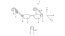
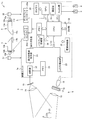
- FIG. 1 is a diagram showing a schematic configuration of a head-mounted display 1 (Head Mounted Display; HMD).
- HMD Head Mounted Display
- the head-mounted display 1 has a mounting part 2 formed in the shape of a frame of spectacles for the user to wear on the head, and a display part that allows the user to recognize an image.
- a right-eye image display unit 3 and a left-eye image display unit 4 are provided.
- the mounting unit 2 includes an infrared light irradiation unit 5 that irradiates the detection target 21 with a predetermined pattern of infrared light, and an infrared light detection unit 6 that detects the infrared light reflected by the detection target 21. Are provided with a predetermined interval.
- the mounting unit 2 includes a control unit 7 (control unit) that controls the right-eye image display unit 3, the left-eye image display unit 4, the infrared light irradiation unit 5, the infrared light detection unit 6, and the like.
- a right earphone 8 is provided on a portion (right vine portion) covering the user's right ear
- a left ear earphone is provided on a portion (left vine portion) covering the user's left ear. 9 are provided.
- the right direction in the figure is the X-axis direction
- the upper direction in the figure is the Y-axis direction
- the X-axis direction and the Y-axis direction are orthogonal
- the front direction in the figure is the Z-axis. Direction.
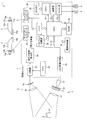
- the right-eye image display unit 3 includes a white LED 10a as a backlight, and light emitted from the white LED 10a is displayed on a liquid crystal display via a condenser lens 11a.
- the transmittance of light in each pixel of the liquid crystal display panel 12a is controlled according to image data that is incident on the panel 12a and is input to the liquid crystal display panel 12a from a display controller, which will be described later, and the light emitted from the white LED 10a is A predetermined image is recognized by the user's right eye through the liquid crystal display panel 12a, the prism 13a, and the lens 14a.
- the image display unit 4 for the left eye includes a white LED 10b as a backlight, and light emitted from the white LED 10b is incident on the liquid crystal display panel 12b via the condenser lens 11b, which will be described later.
- the transmittance of light in each pixel of the liquid crystal display panel 12b is controlled in accordance with image data input from the display controller to the liquid crystal display panel 12b, and the light emitted from the white LED 10b is transmitted to the liquid crystal display panel 12b and the prism 13b.
- the lens 14b the user's left eye recognizes the image as a predetermined image.
- high-temperature polysilicon TFT liquid crystal display panels generally used in projection display devices such as projectors are used as the liquid crystal display panels 12a and 12b, and white light is used as the backlight. Since the LEDs 10a and 10b are used, a high-temperature polysilicon TFT liquid crystal display panel provided with a color filter was used.
- the liquid crystal display panel that can be used in the present embodiment is not limited to this, and includes a high-temperature poly-silicone that includes a red light source, a green light source, and a blue light source as backlights and does not include a color filter for each of the light sources.
- a configuration using three silicon TFT liquid crystal display panels can also be used.
- LCOS Liquid crystal on silicon
- organic EL display OLED Organic Light Emitting Diode
- field emission display FED Field Emission Display
- surface conduction electron-emitting device display SED Surface conduction electron-emitting device display SED (Surf).
- Construction Electron-emitter Display can also be used.
- the head mounted display 1 is provided with an infrared light irradiating unit 5 for irradiating infrared light (IR light) to a finger that is the detection target 21 or a background object of the detection target 21. Yes.
- the infrared light irradiation unit 5 includes an infrared light LED 15, a diffusion plate 16 for making light emitted from the infrared light LED 15 uniform, a microlens array unit 17 having a randomly formed dot pattern, A projection lens 18.
- the light emitted from the infrared light LED 15 is made uniform by the diffusion plate 16, and the infrared light of the dot pattern (predetermined pattern) is detected via the microlens array unit 17 and the projection lens 18.
- the background object of the object 21 is irradiated.
- the microlens array unit 17 provided with a random dot pattern is used, but the pattern provided in the microlens array unit 17 is not particularly limited.
- the head-mounted display 1 detects infrared light reflected from the detection object 21 and the background object of the detection object 21, so that infrared light is detected as the infrared light detection unit 6.
- a camera is provided.
- the infrared light detection unit 6 includes a CCD 19 including a two-dimensionally arranged light receiving element having an infrared light filter that selectively allows only light in the infrared light region to pass through, and condensing light.
- the infrared camera provided with the lens 20 is used, the present invention is not limited to this. If the light receiving element has sensitivity in the infrared light region, for example, the light receiving element is two-dimensional. It is also possible to use an infrared light camera provided with a CMOS or a phototransistor arranged in order.
- the correlator 22 of the control unit 7 includes image data obtained by digitizing the image signal obtained by the infrared light detection unit 6 and a reference pattern (provided in the microlens array unit 17 from the memory 23). Random random dot pattern) image data is input.
- the image data input from the infrared light detection unit 6 and the image data of the reference pattern input from the memory 23 are processed using the triangulation principle described later in detail.
- the fact that the positional deviation of the pattern from the original position on the infrared camera occurs depending on the depth is used.
- the correlator 22 shifts either one of the image data input from the infrared light detection unit 6 and the image data of the reference pattern input from the memory 23 by a predetermined amount, and the other data Is calculated, and the amount of deviation from which the correlation value becomes an extreme value is obtained.
- the correlation calculation is performed in units of small pixel block sizes, but the present invention is not limited to this.
- the depth information restoration unit 24 based on the shift amount obtained by the correlator 22, the depth information of the detection target 21 and the background of the detection target 21 (the direction of the line of sight of the user of the head mounted display 1). A coordinate value in the Z-axis direction) is calculated and supplied to the CPU 26.
- image data input from the infrared light detection unit 6 is supplied from the correlator 22 to the depth information restoration unit 24 together with the depth information, and the depth information restoration unit 24 applies the depth to each of the image data.
- Depth image data to which information has been added is generated and supplied to the CPU 26.
- the LED drive circuit 25 is controlled by the CPU 26 and drives the infrared LED 15.
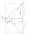
- FIG. 3 and 4 are diagrams for explaining a method of obtaining the depth information using the principle of triangulation in the head mounted display 1.
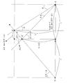
- FIG. 3 and 4 are diagrams for explaining a method of obtaining the depth information using the principle of triangulation in the head mounted display 1.
- FIG. 3 shows a dot pattern provided on a microlens array unit (not shown) of the infrared light irradiation unit 5 on the path of infrared light emitted from a certain pattern inclined to the right by ⁇ from the center. It is a figure for demonstrating the method of calculating
- the center of the infrared light emitted from one dot pattern of the infrared light irradiation unit 5 is inclined to the right by ⁇ , and the infrared light camera as the infrared light detection unit 6 The center is tilted to the left by ⁇ .
- intersection Z between the infrared light emitted from the predetermined dot pattern of the infrared light irradiation unit 5 and the center of the infrared light camera as the infrared light detection unit 6 (the intersection Z is the infrared light irradiation unit 5).
- the reference point in the Z-axis direction that is the direction of the line of sight of the user of the head mounted display 1.
- the dot pattern near one pattern that is inclined to the right by ⁇ from the center irradiated to the detection object, and the detection object The dot pattern in the vicinity of the pattern corresponding to a certain pattern that is reflected and tilted to the right by ⁇ from the center obtained by the infrared light camera as the infrared light detection unit 6 is the same pattern, and No deviation occurs.
- ⁇ is a set value determined by how the infrared light irradiation unit 5 and the infrared light detection unit 6 are provided, ⁇ is obtained by pattern matching of both data described later, and I is infrared. Since it is a half value of the distance between the light irradiation unit 5 and the infrared light detection unit 6 and L can be obtained from I / tan ⁇ , the depth information ⁇ Z ( The coordinate value in the Z-axis direction, which is the direction of the line of sight of the user of the head mounted display 1, can be obtained.
- FIG. 4 shows a path of infrared light emitted from one pattern inclined to the right side by 2 ⁇ from the center in a dot pattern provided in a microlens array section (not shown) of the infrared light irradiation section 5. It is a figure for demonstrating the method of calculating
- the center of the infrared light emitted from one dot pattern of the infrared light irradiation unit 5 is tilted to the right by 2 ⁇ , and the infrared light as the infrared light detection unit 6 is shown.
- the center of the camera is tilted to the left by ⁇ .
- intersection Z between the infrared light emitted from the predetermined dot pattern of the infrared light irradiation unit 5 and the center of the infrared light camera as the infrared light detection unit 6 (the intersection Z is the infrared light irradiation unit 5).
- the reference point in the Z-axis direction that is the direction of the line of sight of the user of the head mounted display 1.
- a dot pattern in the vicinity of a pattern corresponding to a certain pattern which is reflected by an object and obtained by an infrared light camera as the infrared light detection unit 6 and tilted to the right by 2 ⁇ from the center is ⁇ from the center. It is shifted by - ⁇ .
- 2 ⁇ is a set value determined by how the infrared light irradiation unit 5 is provided
- ⁇ is a set value determined by how the infrared light detection unit 6 is provided
- ⁇ is described later.
- Is obtained by pattern matching of the two data I is a half value of the distance between the infrared light irradiation unit 5 and the infrared light detection unit 6, and L is obtained from 2I / (tan ⁇ + tan (2 ⁇ )). Therefore, the depth information ⁇ Z (the coordinate value in the Z-axis direction that is the user's line-of-sight direction of the user of the head-mounted display 1) can be obtained using the above equation (4).
- FIG. 5 is a diagram for explaining a pattern matching method performed for obtaining ⁇ .
- the dot pattern IP (i, j) emitted from the infrared light irradiating unit 5 that irradiates the detection target is shown on the left side of FIG. 5 (a), and on the right side of FIG. 5 (a).
- the image pickup pattern CP (k + i, j) of the camera reflected by the detection object and obtained by the infrared light camera as the infrared light detection unit 6 is illustrated.
- a predetermined area of the dot pattern IP (i, j) emitted from the reference infrared light irradiation unit 5 is obtained by an infrared light camera as the infrared light detection unit 6.
- the correlation value R (k) shown in the following formula (5) was obtained while shifting the image pattern CP (k + i, j) little by little in the left-right direction, that is, while changing the k value.
- a predetermined value of the dot pattern IP (i, j) emitted from the infrared light irradiation unit 5 is used as a reference, and the correlation value R (k) is slightly shifted in the left-right direction with respect to the imaging pattern CP (k + i, j).
- the dot pattern IP (i, j) emitted from the infrared light irradiation unit 5 is slightly shifted in the left-right direction and correlated.
- the value R (k) may be obtained.
- Find k k ′ that maximizes the correlation with (k + i, j), that is, minimizes the correlation value R (k).
- k ′ corresponds to the above-described ⁇ or ⁇ .
- the depth information ⁇ Z of the detection object 21 and the background object of the detection object 21 can be obtained.
- the depth image data to which the depth information ⁇ Z supplied from the information restoration unit 24 is added is converted into image data at a short distance of less than about 1 m from the head mounted display 1. And image data of a long distance of about 1 m or more.
- the depth image data separated as the short-distance image data is used for detecting an input operation to the head-mounted display 1, and the depth image data separated as the long-distance image data is used as the right side of the head-mounted display 1.
- the eye image display unit 3 and the left eye image display unit 4 are displayed as background images.
- FIG. 6 is a diagram for explaining the principle of obtaining coordinates in the X-axis direction and coordinates in the Y-axis direction when a finger as the detection target 21 exists at a short distance of less than about 1 m from the head mounted display 1. It is.
- the dot pattern emitted from the infrared light irradiating unit 5 is reflected only at locations where fingers at different positions exist, and the infrared light detecting unit 6
- the imaging pattern obtained by the infrared light camera is shown. 6A and 6B, it is assumed that the background object is so far away that it cannot be detected by the infrared light detection unit 6.
- the X-axis direction coordinate and the Y-axis direction coordinate can be similarly obtained for the detection target 21 existing at a distance of about 1 m or more from the head mounted display 1.
- the GPU 27 creates an image showing the outline of the detection target 21 based on the depth image data composed of the dot pattern separated as the long-distance image data sent from the CPU 26, and displays it on the display controllers 29 and 30. It is supplied and displayed as a background image on the image display unit 3 for the right eye and the image display unit 4 for the left eye of the head mounted display 1.
- the depth image data composed of the dot patterns separated as the long-distance image data is a discrete value.
- the degree of discrete values must be less than or equal to the step resolution, but if the discrete degree of discrete values is greater than the step resolution, contour lines that are equidistant can be obtained using linear interpolation or the like. .
- an image indicating a contour line of a finger for example, the detection target 21 is created based on the depth image data composed of the dot pattern separated as the short-distance image data sent from the CPU 26. Then, the data is sent to the CPU 26 again.
- the CPU 26 fits data related to the finger skeleton model 21b stored in the memory 31 to an image showing the contour line 21c of the finger, and the tip of the fingertip.
- the X, Y, and Z coordinates of the portion 21a can be obtained.
- the head-mounted display 1 can perform an input operation with higher accuracy.
- An example of the input operation will be described later.
- a content image such as an electronic book acquired via the communication unit 33 is sent to the GPU 27 via the CPU 26, and 3D images (right eye image and left eye image) are created in the GPU 27.
- the 3D image is stored in the 3D memory 28 as needed, and then supplied to the display controllers 29 and 30.
- a content image such as an electronic book can be recognized as a stereoscopic image (3D image) by the user of the head mounted display 1.
- content images such as electronic books can be stored in the memory 31 in advance.
- control unit 7 is connected to the CPU 26, and includes an SW unit 32 (switch unit) including a power switch, a mode setting switch, and other operation switches, and the CPU 26. And a software storage unit 38 in which various types of connected software are stored.
- the software storage unit 38 stores, for example, a coordinate detection algorithm.
- the audio unit 34 analyzes audio data acquired via the communication unit 33 and audio data input from a microphone (not shown) provided in the head mounted display 1 and outputs the audio data from the earphones 8 and 9. ing.
- the power supply unit 35 supplies power to each part of the control unit 7.
- 7 (b), 7 (c), and 7 (d) are diagrams illustrating an example of a specific input operation.
- the above-described input operation can be realized by performing several kinds of gesture recognition based on the temporal change pattern of the tip coordinate of the finger, which is the detection target 21.
- FIG. 7B shows a new page together with an image that is recognized as a page advance gesture when the finger is moved from left to right in the vicinity of the upper left of the virtual book displayed as a content image, and the page of the virtual book is turned.
- a page advance gesture when the finger is moved from left to right in the vicinity of the upper left of the virtual book displayed as a content image, and the page of the virtual book is turned.
- you move your finger from right to left near the upper right of the virtual book it will be recognized as a page return gesture, and the image of the previous page will be displayed along with the image of turning the virtual ebook page. The case is shown.
- (C) of FIG. 7 illustrates a case where the virtual book moves to the right in the initial background coordinates when the finger is moved from left to right in the vicinity of the center of the virtual book.
- FIG. 7D illustrates a case where the size of the virtual book itself increases with the coordinates of the center of the thumb and the index finger when the operation is performed so that the thumb and the index finger are spread on the virtual book. ing.
- the virtual book becomes smaller.
- the input operation is not limited to these.
- the input operation can be performed with or without touching the virtual book, for example, the detection target 21.
- the direction in which the finger as the detection target 21 approaches the virtual book is the Z-axis direction.
- FIG. 9 is a diagram illustrating an example of a method for determining whether or not the finger touches the virtual book based on the coordinate in the Z-axis direction of the tip of the finger that is the detection target 21.
- FIG. 9A shows temporal changes in the coordinates in the Z-axis direction of the tip of the finger that is the detection target 21, and when the coordinates in the Z-axis direction are equal to or greater than a predetermined threshold, the virtual book of the finger This shows a method for determining that there has been a touch to.
- the threshold value can be set as appropriate based on the coordinates in the Z-axis direction for displaying the virtual book.
- FIG. 9B shows temporal changes in coordinates in the Z-axis direction of the tip of the finger, which is the detection object 21, and the coordinates in the Z-axis direction are two threshold values 1 and 2 that are set. Shows a method of determining that a finger touches a virtual book when it exists for a predetermined time.
- FIG. 9C shows the finger virtual book when the value obtained by differentiating the coordinate in the Z-axis direction of the tip of the finger, which is the detection object 21, with respect to time is equal to or greater than a predetermined threshold value for a predetermined time. This shows a method for determining that there is a touch.
- the method for determining whether or not a finger touches the virtual book is not limited to the method shown in FIG. 9, and for example, (a) in FIG. A method combining c) and a method combining (b) of FIG. 9 and (c) of FIG. 9 may be used.
- the CPU 26 calculates the amount of change in posture of the user of the head mounted display 1 that has changed between n frames, thereby converting the virtual book that is the content image into the amount of change in posture of the user. It can be displayed according to.
- each rotation matrix Rx ( ⁇ ), Ry ( ⁇ ) and Rz ( ⁇ ) and the translation matrix T (X, Y, Z) can be expressed by the following formulas (6) to (9).
- the initial background image [xyz] is expressed by (xi, yi, z0 (xi, yi)), and the background image [x′y′z ′] after n frames is (xi, yi). , Zn (xi, yi)), the posture change amount Rx ( ⁇ ) Ry ( ⁇ ) Rz ( ⁇ ) T (X, Y, Z) of the user of the head mounted display 1 that has changed between n frames. ) Can be calculated backwards.
- a predetermined background image for example, an initial background image is always displayed on the right-eye image display unit 3 and the left-eye image display unit 4 of the head mounted display 1, the initial coordinate value of the virtual book that is the content image Is converted and displayed by the user's posture change amount Rx ( ⁇ ) Ry ( ⁇ ) Rz ( ⁇ ) T (X, Y, Z), so that only the virtual book changes the user's posture. It is possible to realize a mode (tool mounting mode) that follows as much as possible.
- the user can select the tool mounting mode and the MR mode.
- the user wearing the head mounted display 1 can lie down and see an image of predetermined information in a comfortable posture, and also performs an input operation in a dark place such as a bedroom. be able to.
- the head-mounted display 1a includes a right-eye imaging device 36 and a left-eye imaging device 37 for capturing a background image as a color image in order to improve the reality.
- the second embodiment is different from the first embodiment, and other configurations are the same as those described in the first embodiment.
- members having the same functions as those shown in the drawings of the first embodiment are given the same reference numerals, and descriptions thereof are omitted.
- FIG. 11 is a diagram showing a schematic configuration of a head mounted display 1a including a right eye imaging device 36 (color camera) and a left eye imaging device 37 (color camera).
- the mounting unit 2 of the head-mounted display 1 a is provided with a right-eye imaging device 36 adjacent to the infrared light detection unit 6 and adjacent to the infrared light irradiation unit 5.
- a left-eye imaging device 37 is provided at the place to be operated.
- the right-eye imaging device 36 and the left-eye imaging device 37 are provided at a predetermined distance so as to capture a right-eye image and a left-eye image having binocular parallax.
- FIG. 12 is a diagram for explaining each part of the head mounted display 1a.
- the right-eye color image captured from the right-eye imaging device 36 and the left-eye color image captured from the left-eye imaging device 37 are stored in the 3D memory in the control unit 7a.
- the CPU 26 stores the color image for the right eye and the color for the left eye from the color image for the right eye and the color image for the left eye by using a phase only correlation method to be described later in detail.
- the depth information with the color image is calculated.
- the color image for the right eye of the content image such as the virtual book or virtual temple created in the GPU 27 is used as the 3D image.
- a color image for the right eye obtained by transparently combining the color image for the right eye of the content image and the color image for the right eye of the background image so as to be positioned in front of the color image for the right eye of the image. It is prepared and supplied to the display controller 29a.
- the color image for the left eye of the content image such as the virtual book or virtual temple created by the GPU 27 is used as the 3D image.
- a color image for the left eye obtained by transparently synthesizing the color image for the left eye of the content image and the color image for the left eye of the background image so as to be positioned in front of the color image for the left eye of the background image Is generated and supplied to the display controller 30a.
- the user of the head mounted display 1a can recognize the content image such as the virtual book or the virtual temple so as to be positioned in front of the background image.
- only the content image may be preferentially seen in a portion where the content image and the background image overlap.
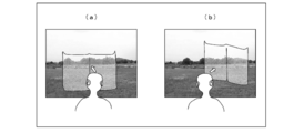
- FIG. 13 shows an example when the MR mode is realized in the head mounted display 1a.
- FIG. 13A shows a color image of a 3D background image that is captured from the right-eye imaging device 36 and the left-eye imaging device 37 and recognized by the user of the head-mounted display 1a.
- the color image of the 3D background image changes one after another according to the change in the posture of the user.
- FIG. 13B shows a case where a virtual temple as a content image is superimposed on the color image of the 3D background image so that only the content image can be seen preferentially. ing.
- the background image changes one after another according to the change in the posture of the user, but the virtual temple that is the content image is placed at a predetermined position. Can be displayed.
- FIG. 14 shows an example when the tool mounting mode is realized in the head mounted display 1a.
- the background image recognized by the user is always the same even if the posture of the user of the head mounted display 1a changes.
- the virtual book that is the content image can be attached as much as the user's attitude changes.
- 14A and 14B show a case where the content image is transparently combined on the front side of the background image, and the background image behind is displayed through the content image. It can be seen to some extent.
- phase-only correlation method is used to calculate depth information with higher accuracy, but other correlation methods may be used.
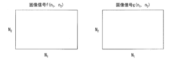
- FIG. 15 illustrates a right-eye color image f (n 1 , n 2 ) captured from the right-eye imaging device 36 and a left-eye color image captured from the left-eye imaging device 37 in a certain same frame. It is a diagram illustrating the magnitude of the g (n 1, n 2) .
- the color image f (n 1 , n 2 ) for the right eye and the color image g (n 1 , n 2 ) for the left eye are the same images that are slightly misaligned, and their sizes are illustrated. Thus, N 1 ⁇ N 2 .
- N 2 2M 2 +1, F (k 1 , k 2 ) and G (k 1 , n) obtained by two-dimensional discrete Fourier transform of the image f (n 1 , n 2 ) and the image g (n 1 , n 2 ).
- k 2 ) can be obtained by the following formula (12) and the following formula (13).
- a F (k 1 , k 2 ) is the amplitude component of the image f (n 1 , n 2 ), e j ⁇ f (k1, k2) is the phase component of the signal,
- a G (k 1 , k 2 ) is an amplitude component of the image g (n 1 , n 2 ), and e j ⁇ g (k1, k2) is a phase component of the signal.
- phase-only correlation function r (n 1 , n 2 ) represented by the following formula (15) can be obtained by inverse Fourier transform of the above formula (14).
- phase-only correlation function in the case of an image defined in continuous space, a phase-only correlation function can be obtained as follows.
- a discrete sample of the original image is a right-eye color image f (n 1 , n 2 ) captured from the right-eye imaging device 36, and the shifted image is used for the left-eye captured from the left-eye imaging device 37.
- the color image is g (n 1 , n 2 )
- the image f (n 1 , n 2 ) is defined as in the following equation (16)
- the image g (n 1 , n 2 ) is defined as in the following equation (17 ).
- F (k 1 , k 2 ) and G (k 1 , k 2 ) obtained by two-dimensional discrete Fourier transform of the image f (n 1 , n 2 ) and the image g (n 1 , n 2 ) are circulated. Therefore, discontinuity occurs at the image edge, and aliasing distortion occurs.
- Hanning window functions as shown in the following equation (20) are applied to the image f (n 1 , n 2 ) and the image g (n 1 , n 2).
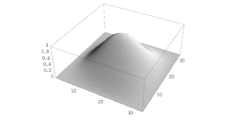
- FIG. 16 is an example of a Hanning window used when performing image matching based on the phase-only correlation method, and shows a spatial filter for reducing the influence of aliasing distortion.
- FIG. 16 is a visualization of the above equation (20), and the offset (0, 0) corresponds to (16, 16).
- a natural image captured by a camera such as the right-eye imaging device 36 or the left-eye imaging device 37 is predicted to have a lower S / N ratio in the high frequency region than in the low frequency region.
- a square-type low-pass filter as a weighting function, a high-frequency component with low reliability is removed, and high accuracy is realized.
- U 1 and U 2 are integers satisfying 0 ⁇ U 1 ⁇ M 1 and 0 ⁇ U 2 ⁇ M 2 , respectively.
- FIG. 17A shows the spectrum of a rectangular low-pass filter H (k 1 , k 2 ) as a weighting function
- FIG. 17B shows the phase limitation corresponding thereto. The correlation function is shown.
- FIG. 18 is a diagram showing the relationship between the phase-only correlation function shown in the above equation (23) and the coordinate points.
- the subpixel movement amount ⁇ is expressed by the following equation (25).
- the square error shown in the following equation (28) may be minimized.
- FIGS. 19A to 19D are diagrams showing a method of estimating the subpixel movement amount ⁇ from the center of the first peak of the phase-only correlation function, from FIG.
- FIG. 20D is a diagram illustrating a method of estimating the sub-pixel movement amount ⁇ from the second peak center of the phase-only correlation function.
- the Hanning window shown in the above equation (20) is displayed on the image f (n 1 , n 2 ) and the image g (n 1 , n 2 ) slightly shifted by the CPU 28 in the control unit 7a.
- an image fw (n 1 , n 2 ) and an image gw (n 1 , n 2 ) are generated.
- R (k 1 , k 2 ) is generated by normalizing the absolute values of the coefficients of F (k 1 , k 2 ) and G (k 1 , k 2 ) based on the above equation (14).
- R (k 1 , k 2 ) is subjected to inverse Fourier transform to obtain a phase only correlation function r (n 1 , n 2 ), and as shown in FIG. 19, the phase only correlation function r (n 1 , n 2 ), the position of the first peak is determined and associated with p 1 , and the position of the second peak of the phase-only correlation function r (n 1 , n 2 ) is determined as shown in FIG. Corresponding to the request p l + 1 .
- control unit may perform an input operation based on a change during a predetermined period of the coordinate value of the detection target object in which the coordinate value in the third axial direction is less than a predetermined value. It is preferable to determine the type.
- control unit is configured to detect the detection object whose coordinate value in the third axial direction is less than a predetermined value, that is, the detection object present at a relatively short distance from the head mounted display.
- the input object is determined as a detection object, and the type of the input operation is determined based on the change in the coordinate value of the detection object during a predetermined period.
- a head mounted display capable of performing an input operation can be realized.
- the detection object whose coordinate value in the third axial direction is less than a predetermined value is the user's finger, and the coordinate value of the finger is reflected by the finger. It is preferable that the coordinate value of the fingertip in the image obtained by fitting the skeleton image of the finger to the image showing the outline of the finger created based on the predetermined pattern.
- the control unit is reflected by the detection object whose coordinate value in the third axial direction obtained by the infrared light detection unit at a first time is equal to or greater than a predetermined value.
- An image showing the outline of the detection object created based on the predetermined pattern is displayed on the display unit as a background image, and the predetermined pattern obtained by the infrared light detection unit at the first time
- the user's posture change amount from the predetermined pattern reflected by the detection target obtained at the second time after a predetermined period, and the content image is displayed on the display unit by the posture change amount. You may move and display.
- control unit is configured such that the coordinate value in the third axial direction obtained by the infrared light detection unit at the first time is equal to or greater than a predetermined value, that is, compared with the head mounted display.
- the detection object present at a long distance is recognized as a background.
- the said 3rd axial direction coordinate value obtained by the said infrared light detection part in the said 1st time was created based on the predetermined pattern reflected by the said detection target object more than predetermined value
- An image showing the outline of the detection target is always displayed on the display unit as a background image.
- the user From the predetermined pattern obtained by the infrared light detection unit at the first time and the predetermined pattern reflected by the detection object obtained at the second time after a predetermined period, the user The posture change amount can be calculated, and only the content image to be displayed on the display unit can be moved and displayed by the posture change amount.
- the control unit is based on a predetermined pattern reflected by the detection object whose coordinate value in the third axial direction obtained by the infrared light detection unit is a predetermined value or more.
- the image showing the contour line of the detection object created in the above is sequentially displayed on the display unit as a background image, and a predetermined pattern obtained by the infrared light detection unit at a first time, and a predetermined pattern
- the posture change amount of the user is calculated from the predetermined pattern reflected by the detection target obtained at the second time after the period, and the content image is displayed on the display unit in a direction opposite to the posture change amount. The amount of change may be moved and displayed.
- the background that the user can see changes one after another according to the change in the posture of the user.
- the background that can be seen through the display unit by the user according to the change in the posture of the user as in the case where the head mounted display is not mounted Can be changed one after another.
- the content image displayed on the display unit is displayed by being moved by a change amount in a direction opposite to the posture change amount of the user, the content image has a background that changes one after another. It can be fixed at a predetermined location of the image.
- the display unit includes a left-eye image display unit that displays a left-eye image and a right-eye image display unit that displays a right-eye image.
- the mounting unit includes a left-eye imaging device that captures the left-eye image of the background image and a right-eye imaging device that captures the right-eye image of the background image with a predetermined interval.
- the control unit includes the background image and the left-eye image of the content image on the left-eye image display unit, and the background image and the right-eye image of the content image on the right-eye image display unit. A configuration in which the images are alternately displayed at predetermined intervals may be employed.
- the background image and the content image can be recognized by the user as a stereoscopic image having a sense of depth, a head-mounted display with a further increased realism can be realized.
- control unit obtains depth information from the left-eye image and the right-eye image of the background image by a correlation method, and based on the depth information, the background image and the content It is preferable to perform synthesis with an image.
- the correlation method is preferably a phase only correlation method.
- a composite image of the background image and the content image can be generated based on the depth information of the background image obtained using a correlation method such as a phase-only correlation method.
- a head mounted display with increased realism can be realized.
- phase only correlation method when used as the correlation method, more accurate depth information can be obtained.
- the background image and the content image are synthesized so that the user can see the background image through the content image.
- the user since the user can see the background image through the content image, the user can enjoy the content image and the background image at the same time.
- the left eye imaging device and the right eye imaging device are preferably color imaging devices capable of capturing a color image.
- the control unit of the head-mounted display of the present invention is configured to determine the predetermined coordinate values in the first axial direction and the second axial direction of the detection target object whose coordinate values in the third axial direction are less than a predetermined value. Based on the change during the period, it is selected whether to perform any one of enlargement, reduction, movement and image conversion on the content image displayed on the display unit, and the detection object 3 based on the change of the coordinate value in the axial direction of 3 for a predetermined period, the presence / absence of touch on the content image displayed on the display unit of the detection target is determined.
- a configuration may be adopted in which the content image displayed on the display unit is displayed after the above operation is performed.
- the control unit has a predetermined period of the coordinate values in the first axial direction and the second axial direction of the detection object whose coordinate value in the third axial direction is less than a predetermined value.
- the type of operation for performing enlargement, reduction, movement, image conversion, and the like on the content image displayed on the display unit is determined based on the change between and the third axial direction of the detection target Whether to perform the operation on the content image displayed on the display unit is determined based on a change in the coordinate value during a predetermined period.
- the present invention can be suitably used for a head mounted display or the like.
Landscapes
- Engineering & Computer Science (AREA)
- Physics & Mathematics (AREA)
- General Engineering & Computer Science (AREA)
- Theoretical Computer Science (AREA)
- General Physics & Mathematics (AREA)
- Human Computer Interaction (AREA)
- Multimedia (AREA)
- Signal Processing (AREA)
- Optics & Photonics (AREA)
- Spectroscopy & Molecular Physics (AREA)
- Electromagnetism (AREA)
- User Interface Of Digital Computer (AREA)
Abstract
使用者が頭部に装着するための装着部(2)には、検出対象物(21)に所定パターンの赤外光を照射する赤外光照射部(5)と、検出対象物(21)によって反射された上記赤外光を検出する赤外光検出部(6)と、が所定間隔を有して備えられており、赤外光検出部(6)によって得られた検出対象物(21)によって反射された所定パターンから、検出対象物(21)の3次元座標を算出する。
Description
本発明は、検出対象物の3次元座標の算出が可能なヘッドマウントディスプレイに関するものである。
近年、インターネットなどの発達に伴い、あらゆる情報の電子化がなされ、電子ブックやスマートフォンなどの携帯型端末機を用いて、例えば、電子書籍や各種の電子化された情報などを見るのが一般的になっている。
電子ブックやスマートフォンなどの携帯型端末機は、テーブルなどに置いて使用する場合もあるが、例えば、寝ころんで楽な姿勢で使用する場合も多い。
図21に図示されているように、電子ブックやスマートフォンなどの携帯型端末機90を寝ころんで使用する場合、携帯型端末機90を一方の手で保持しなければならず、携帯型端末機90に所定の入力操作を行うためには、携帯型端末機90を使用者の近くに持ってきて、他方の手で入力操作を行う必要がある。
したがって、携帯型端末機90の製品の重さによって、手に疲れが生じたり、携帯型端末機90を使用者91の近くに持ってきて、入力操作を行う必要があるため不便であった。
そこで、特許文献1に記載されているような手位置動作検出手段を備えたヘッドマウントディスプレイが注目されている。
図22は、特許文献1に記載の手位置動作検出手段を備えたヘッドマウントディスプレイの概略構成を示す図である。
図示されているように、ヘッドマウントディスプレイ100は、頭部装着部110と、画像生成部120と、撮像装置131・132と、制御部140と、から構成されている。
頭部装着部110は、ユーザの頭部に装着できるように眼鏡のフレーム形状に形成されている。
画像生成部120は、頭部装着部110の側前部に取り付けられており、画像を生成し、当該画像をユーザに視認させるものである。
そして、イメージセンサや結像光学系等から構成される撮像装置131・132は、一定間隔をおいて頭部装着部110の前部に取り付けられている。
制御部140は、ヘッドマウントディスプレイ100を制御するものであり、画像生成部120と撮像装置131・132とに接続されている。
上記構成によれば、画像生成部120が、奥行き方向(ユーザ視線の手前から遠い方向)に積層配置したように見える複数の仮想パネル画像を生成し、ユーザの手(指)150が、ある仮想パネルに、一定時間以上とどまった場合には、当該仮想パネルに対応するコマンドが実行されるようになっている。
すなわち、左右の撮像装置131・132から得られるユーザの手(指)150の画像から、制御部140は、ユーザの手(指)150の奥行き方向の座標を検出し、ある仮想パネルにユーザの手(指)150が一定時間以上とどまったか否かを判断するようになっている。
このような構成とすることにより、携帯型端末機を手に持つことなく、所定情報の画像を見ることができるとともに、入力操作も行うことができる装置を実現することができる。
また、さらに特許文献1には、ユーザの手(指)150に、ユーザの手の動作(例えば、指を曲げた等)を検出するセンサー160を取り付けた構成についても開示されている。
上記構成によれば、ユーザの手の動作を検出して、入力操作を行う装置を実現することができる。
そして、特許文献2には、対象物の3次元マッピングに用いることができる光マッピングシステムについて記載されている。
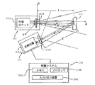
図23は、特許文献2に記載の光マッピングシステムの概略構成を示す図である。
図示されているように、光マッピングシステムには、対象物213上にランダムスペックルパターン(望ましくは一定パターン)を投影するように構成された照明ユニット212と、画像化装置214と、が備えられている。
照明ユニット212には、光源ユニット212Aと、光源ユニット212Aからの照明光の光路内に収容され、光源出力に非常に近接していることが望ましい一定ランダムスペックルパターンの発生器212Bと、が備えられている。
一方、画像化装置214には、対象物213からの反射光を検出できるように、画像レンズ214Bを備えた光検出器214A(ピクセルマトリクス、例えばCCD)が備えられている。
そして、制御システム216は、画像化装置214の出力に接続されており、制御システム216には、メモリ216Aと、データの処理および解析を行うプロセッサ216Bと、入力/出力装置216C(例えば、表示装置のようなデータ提示部)と、が備えられている。
画像化装置214は、照明領域の光応答(光反射)を検出して、画像データを生成するように構成され、上記画像データは、投影スペックルパターンを有する対象物213を示しており、上記パターンの参照画像に対する対象物213の画像におけるパターンのずれを示している。
上記構成によれば、対象物213の3次元マップの実時間再構成が可能になると記載されている。
しかしながら、図22に示す特許文献1に開示されている構成は、アクティブな照明を備えてない構成であるため、寝室などの暗いところでは、ユーザの手(指)150の位置を検出できないという問題がある。
また、図23に示す特許文献2に開示されている光マッピングシステムは、制御システム216に備えられた入力/出力装置216C(表示装置)とは、独立しているため、上記光マッピングシステムに備えられた画像化装置214は、入力/出力装置216C(表示装置)が動いたとしても、この動きに応じた画像データを生成することができない。
したがって、使用者の姿勢変化などによって、その向きが頻繁に変わることが想定される表示装置であるヘッドマウントディスプレイにおいては、上記光マッピングシステムを用いて、対象物の3次元座標を検出するのは困難である。
本発明は、上記の問題点に鑑みてなされたものであり、寝室などの暗いところにおいても、検出対象物の3次元座標の算出が可能であり、ヘッドマウントディスプレイを装着した使用者が首などを動かしても、この動きに応じた検出対象物の3次元座標の算出が可能なヘッドマウントディスプレイを提供することを目的とする。
本発明のヘッドマウントディスプレイは、上記の課題を解決するために、使用者に画像を認識させる表示部を備え、検出対象物の3次元座標を算出できるヘッドマウントディスプレイであって、上記使用者が頭部に装着するための装着部には、上記検出対象物に所定パターンの赤外光を照射する赤外光照射部と、上記検出対象物によって反射された上記赤外光を検出する赤外光検出部と、が所定間隔を有して備えられており、制御部には、上記3次元座標の算出部が備えられており、上記算出部は、上記赤外光検出部によって得られた上記検出対象物によって反射された所定パターンから、互いに直交する第1の軸方向および第2の軸方向の座標値を算出し、上記検出対象物に照射される所定パターンと上記赤外光検出部によって得られた上記検出対象物によって反射された所定パターンとのずれ量から、上記第1の軸方向および上記第2の軸方向と直交し、かつ、上記使用者の視線方向である第3の軸方向の座標値を算出することを特徴としている。
上記構成によれば、赤外光照射部と赤外光検出部とが備えられているため、例えば、寝室などの暗いところにおいても、検出対象物の3次元座標の算出が可能となる。
また、上記構成によれば、赤外光照射部と赤外光検出部とが上記使用者が頭部に装着するための装着部に備えられているため、例えば、上記使用者が首などを動かしても、この動きに応じた検出対象物の3次元座標の算出が可能となる。
したがって、上記構成によれば、寝室などの暗いところにおいても、検出対象物の3次元座標の算出が可能であり、ヘッドマウントディスプレイを装着した使用者が首などを動かしても、この動きに応じた検出対象物の3次元座標の算出が可能なヘッドマウントディスプレイを実現することができる。
本発明のヘッドマウントディスプレイは、以上のように、上記使用者が頭部に装着するための装着部には、上記検出対象物に所定パターンの赤外光を照射する赤外光照射部と、上記検出対象物によって反射された上記赤外光を検出する赤外光検出部と、が所定間隔を有して備えられており、制御部には、上記3次元座標の算出部が備えられており、上記算出部は、上記赤外光検出部によって得られた上記検出対象物によって反射された所定パターンから、互いに直交する第1の軸方向および第2の軸方向の座標値を算出し、上記検出対象物に照射される所定パターンと上記赤外光検出部によって得られた上記検出対象物によって反射された所定パターンとのずれ量から、上記第1の軸方向および上記第2の軸方向と直交し、かつ、上記使用者の視線方向である第3の軸方向の座標値を算出する構成である。
それゆえ、寝室などの暗いところにおいても、検出対象物の3次元座標の算出が可能であり、ヘッドマウントディスプレイを装着した使用者が首などを動かしても、この動きに応じた検出対象物の3次元座標の算出が可能なヘッドマウントディスプレイを実現することができる。
以下、図面に基づいて本発明の実施の形態について詳しく説明する。ただし、この実施の形態に記載されている構成部品の寸法、材質、形状、その相対配置などはあくまで一実施形態に過ぎず、これらによってこの発明の範囲が限定解釈されるべきではない。
なお、以下の実施の形態においては、3D用のヘッドマウントディスプレイを前提に説明をするが、これに限定されることはない。
〔実施の形態1〕
図1は、ヘッドマウントディスプレイ1(Head Mounted Display;HMD)の概略構成を示す図である。
図1は、ヘッドマウントディスプレイ1(Head Mounted Display;HMD)の概略構成を示す図である。
図示されているように、ヘッドマウントディスプレイ1には、使用者が頭部に装着するため、眼鏡のフレーム形状に形成されている装着部2と、上記使用者に画像を認識させる表示部として、右眼用画像表示部3および左眼用画像表示部4と、が備えられている。
そして、装着部2には、検出対象物21に所定パターンの赤外光を照射する赤外光照射部5と検出対象物21によって反射された上記赤外光を検出する赤外光検出部6とが、所定間隔を有して設けられている。
さらに、装着部2には、右眼用画像表示部3および左眼用画像表示部4と赤外光照射部5と赤外光検出部6などを制御する制御ユニット7(制御部)が備えられているとともに、上記使用者の右耳にかかる部分(右側のつる部分)には右耳用イヤホン8が、上記使用者の左耳にかかる部分(左側のつる部分)には左耳用イヤホン9が、それぞれ設けられている。
なお、図示されているように、図中の右方向がX軸方向、図中の上方向がY軸方向、上記X軸方向と上記Y軸方向と直交し、図中の手前方向がZ軸方向である。
以下、図2に基づいて、右眼用画像表示部3、左眼用画像表示部4、赤外光照射部5、赤外光検出部6および制御ユニット7の各構成についてさらに詳しく説明する。
(右眼用画像表示部および左眼用画像表示部の構成)
図2に図示されているように、右眼用画像表示部3には、バックライトとして白色LED10aが備えられており、白色LED10aから出射された光は、集光レンズ11aを介して、液晶表示パネル12aに入射され、後述するディスプレイコントローラから液晶表示パネル12aに入力される画像データに応じて、液晶表示パネル12aの各画素における光の透過率が制御され、白色LED10aから出射された光は、液晶表示パネル12aとプリズム13aとレンズ14aとを介して、所定画像として使用者の右眼に認識されるようになっている。
(右眼用画像表示部および左眼用画像表示部の構成)
図2に図示されているように、右眼用画像表示部3には、バックライトとして白色LED10aが備えられており、白色LED10aから出射された光は、集光レンズ11aを介して、液晶表示パネル12aに入射され、後述するディスプレイコントローラから液晶表示パネル12aに入力される画像データに応じて、液晶表示パネル12aの各画素における光の透過率が制御され、白色LED10aから出射された光は、液晶表示パネル12aとプリズム13aとレンズ14aとを介して、所定画像として使用者の右眼に認識されるようになっている。
同様に、左眼用画像表示部4には、バックライトとして白色LED10bが備えられており、白色LED10bから出射された光は、集光レンズ11bを介して、液晶表示パネル12bに入射され、後述するディスプレイコントローラから液晶表示パネル12bに入力される画像データに応じて、液晶表示パネル12bの各画素における光の透過率が制御され、白色LED10bから出射された光は、液晶表示パネル12bとプリズム13bとレンズ14bとを介して、所定画像として使用者の左眼に認識されるようになっている。
なお、本実施の形態においては、液晶表示パネル12a・12bとして、プロジェクターなどの投射型表示装置において一般的によく用いられている高温ポリシリコンTFT液晶表示パネルを用いており、バックライトとして、白色LED10a・10bを用いているため、カラーフィルターを備えた高温ポリシリコンTFT液晶表示パネルを用いた。
本実施の形態において用いることができる液晶表示パネルとしては、これに限定されず、バックライトとして赤色光源、緑色光源および青色光源をそれぞれ備え、上記それぞれの光源用としてカラーフィルターを備えてない高温ポリシリコンTFT液晶表示パネル3枚を用いた構成とすることもできる。
また、液晶表示パネル以外にも、LCOS(Liquid crystal on silicon)や有機ELディスプレイOLED(Organic Light Emitting Diode)、電界放出型ディスプレイFED(Field Emission Display)、表面伝導型電子放出素子ディスプレイSED(Surface-conduction Electron-emitter Display)などを用いることもできる。
(赤外光照射部)
そして、ヘッドマウントディスプレイ1には、検出対象物21である指や検出対象物21の背景物に対して、赤外光(IR光)を照射するための赤外光照射部5が備えられている。
(赤外光照射部)
そして、ヘッドマウントディスプレイ1には、検出対象物21である指や検出対象物21の背景物に対して、赤外光(IR光)を照射するための赤外光照射部5が備えられている。
赤外光照射部5は、赤外光LED15と、赤外光LED15から出射された光を均一にするための拡散板16と、ランダムに形成されたドットパターンを有するマイクロレンズアレイ部17と、投射レンズ18と、を備えている。
赤外光LED15から出射された光は、拡散板16によって均一化され、マイクロレンズアレイ部17と投射レンズ18とを介して、ドットパターン(所定パターン)の赤外光が検出対象物21や検出対象物21の背景物に照射されるようになっている。
なお、本実施の形態においては、ランダムドットパターンが設けられたマイクロレンズアレイ部17を用いているが、マイクロレンズアレイ部17に設けるパターンは、特に限定されない。
(赤外光検出部)
そして、図示されているように、ヘッドマウントディスプレイ1には、検出対象物21や検出対象物21の背景物から反射された赤外光を検出するため、赤外光検出部6として赤外光カメラが備えられている。
(赤外光検出部)
そして、図示されているように、ヘッドマウントディスプレイ1には、検出対象物21や検出対象物21の背景物から反射された赤外光を検出するため、赤外光検出部6として赤外光カメラが備えられている。
本実施の形態においては、赤外光検出部6として、赤外光領域の光のみを選択的に通す赤外光フィルターを有する2次元的に配列された受光素子を備えたCCD19と、集光レンズ20と、を備えた赤外光カメラを用いているが、これに限定されることはなく、受光素子が上記赤外光領域に感度を有するのであれば、例えば、上記受光素子が2次元的に配列されたCMOSやフォトトランジスタなどを備えた赤外光カメラを用いることもできる。
(制御ユニット)
図示されているように、制御ユニット7の相関器22には、赤外光検出部6で得られた画像信号をデジタル化した画像データと、メモリ23から基準パターン(マイクロレンズアレイ部17に設けられたランダムドットパターン)の画像データと、が入力されるようになっている。
(制御ユニット)
図示されているように、制御ユニット7の相関器22には、赤外光検出部6で得られた画像信号をデジタル化した画像データと、メモリ23から基準パターン(マイクロレンズアレイ部17に設けられたランダムドットパターン)の画像データと、が入力されるようになっている。
相関器22においては、赤外光検出部6から入力された画像データと、メモリ23から入力された基準パターンの画像データと、を詳しくは後述する三角測量の原理を用いて、両データのパターンのマッチングをとることによって、奥行きの大きさによって、赤外光カメラ上の本来の位置からのパターンの位置ずれが発生することを利用する。
すなわち、相関器22においては、赤外光検出部6から入力された画像データとメモリ23から入力された基準パターンの画像データとの何れか一方のデータを所定量ずつずらしながら、他方のデータとの相関計算を行い、相関値が極値となるずれ量を求める。
なお、本実施の形態においては、上記相関計算は、小さい画素ブロックのサイズ単位で計算を行っているが、これに限定されることはない。
そして、奥行き情報復元部24においては、相関器22において求めたずれ量に基づいて、検出対象物21や検出対象物21の背景物の奥行き情報(ヘッドマウントディスプレイ1の使用者の視線方向であるZ軸方向の座標値)を算出し、CPU26に供給する。
すなわち、相関器22から奥行き情報復元部24には、上記奥行き情報とともに、赤外光検出部6から入力された画像データも供給され、奥行き情報復元部24では、それぞれの上記画像データに上記奥行き情報が加えられた奥行き画像データが生成され、CPU26に供給されるようになっている。
なお、LED駆動回路25はCPU26によって制御され、赤外光LED15を駆動するためのものである。
以下、図3、図4および図5に基づいて、両データのパターンのマッチングをとることによって、上記奥行き情報を求める方法について具体的に説明する。
図3および図4は、ヘッドマウントディスプレイ1において、三角測量の原理を用いて上記奥行き情報を求める方法を説明するための図である。
図3は、赤外光照射部5のマイクロレンズアレイ部(未図示)に設けられたドットパターン中、中心からθだけ右側に傾いているある一つのパターンから出射した赤外光の経路上に、検出対象物が存在する場合において、その奥行き情報を求める方法を説明するための図である。
図示されているように、赤外光照射部5のある一つのドットパターンから出射された赤外光の中心はθだけ右側に傾いており、赤外光検出部6としての赤外光カメラの中心はθだけ左側に傾いている。
赤外光照射部5の上記所定のドットパターンから出射された赤外光と、赤外光検出部6としての赤外光カメラの中心との交点Z(交点Zは、赤外光照射部5と赤外光検出部6とを結ぶ直線からの最短距離でLだけ離れている)の位置を、ヘッドマウントディスプレイ1の使用者の視線方向であるZ軸方向の基準点とする。
検出対象物が基準点である交点Zの位置にある時においては、検出対象物に照射される上記中心からθだけ右側に傾いているある一つのパターン近傍のドットパターンと、上記検出対象物によって反射され、赤外光検出部6としての赤外光カメラによって得られる上記中心からθだけ右側に傾いているある一つのパターンに対応するパターン近傍のドットパターンとは、同じパターンとなり、中心に対してずれは生じない。
一方、検出対象物が、中心から赤外光照射部5側であり、交点ZよりΔZ分だけ手前の位置Z’にある時には、下記式(1)が成立する。

そして、上記式(1)をΔZについて、整理すると下記式(2)となる。

上記式(2)において、θは、赤外光照射部5および赤外光検出部6の設け方によって定まる設定値であり、Δθは後述する両データのパターンマッチングによって得られ、Iは赤外光照射部5と赤外光検出部6との間の距離の半値であり、LはI/tanθから求めることができるので、上記式(2)を用いて、検出対象物の奥行き情報ΔZ(ヘッドマウントディスプレイ1の使用者の視線方向であるZ軸方向の座標値)を求めることができる。
図4は、赤外光照射部5のマイクロレンズアレイ部(未図示)に設けられたドットパターン中、中心から2θ-φだけ右側に傾いているある一つのパターンから出射した赤外光の経路上に、検出対象物が存在する場合において、その奥行き情報を求める方法を説明するための図である。
図示されているように、赤外光照射部5のある一つのドットパターンから出射された赤外光の中心は2θ-φだけ右側に傾いており、赤外光検出部6としての赤外光カメラの中心はφだけ左側に傾いている。
赤外光照射部5の上記所定のドットパターンから出射された赤外光と、赤外光検出部6としての赤外光カメラの中心との交点Z(交点Zは、赤外光照射部5と赤外光検出部6とを結ぶ直線からの最短距離でLだけ離れている)の位置を、ヘッドマウントディスプレイ1の使用者の視線方向であるZ軸方向の基準点とする。
検出対象物が基準点である交点Zの位置にある時においては、検出対象物に照射される上記中心から2θ-φだけ右側に傾いているある一つのパターン近傍のドットパターンと、上記検出対象物によって反射され、赤外光検出部6としての赤外光カメラによって得られる上記中心から2θ-φだけ右側に傾いているある一つのパターンに対応するパターン近傍のドットパターンとは、中心からθ-φだけずれている。
一方、検出対象物が、中心から赤外光検出部6側であり、交点ZよりΔZ分だけ手前の位置Z’にある時には、下記式(3)が成立する。

そして、上記式(3)をΔZについて、整理すると下記式(4)となる。

上記式(4)において、2θ-φは、赤外光照射部5の設け方によって定まる設定値であり、φは、赤外光検出部6の設け方によって定まる設定値であり、Δφは後述する両データのパターンマッチングによって得られ、Iは赤外光照射部5と赤外光検出部6との間の距離の半値であり、Lは2I/(tanφ+tan(2θ-φ))から求めることができるので、上記式(4)を用いて、検出対象物の奥行き情報ΔZ(ヘッドマウントディスプレイ1の使用者の視線方向であるZ軸方向の座標値)を求めることができる。
図5は、Δφを求めるために行われるパターンマッチング方法を説明するための図である。
図5の(a)の左側には、検出対象物に照射される赤外光照射部5から出射されるドットパターンIP(i、j)が図示されており、図5(a)の右側には、上記検出対象物によって反射され、赤外光検出部6としての赤外光カメラによって得られるカメラでの撮像パターンCP(k+i、j)が図示されている。
そして、図示されているように、基準となる赤外光照射部5から出射されるドットパターンIP(i、j)の所定領域を、赤外光検出部6としての赤外光カメラによって得られた撮像パターンCP(k+i、j)に対して、左右方向に少しずつずらしながら、すなわち、k値を変化させながら下記式(5)に示す相関値R(k)を求めた。

なお、本実施の形態においては、小さい画素ブロックのサイズ単位で計算を行うため、
赤外光照射部5から出射されるドットパターンIP(i、j)の所定領域を基準とし、撮像パターンCP(k+i、j)に対して、左右方向に少しずつずらし、相関値R(k)を求めたが、撮像パターンCP(k+i、j)の所定領域を基準とし、赤外光照射部5から出射されるドットパターンIP(i、j)に対して、左右方向に少しずつずらし、相関値R(k)を求めてもよい。
赤外光照射部5から出射されるドットパターンIP(i、j)の所定領域を基準とし、撮像パターンCP(k+i、j)に対して、左右方向に少しずつずらし、相関値R(k)を求めたが、撮像パターンCP(k+i、j)の所定領域を基準とし、赤外光照射部5から出射されるドットパターンIP(i、j)に対して、左右方向に少しずつずらし、相関値R(k)を求めてもよい。
図5の(b)に図示されているように、k値を-I~+Iの範囲で変化させながら、赤外光照射部5から出射されるドットパターンIP(i、j)と撮像パターンCP(k+i、j)との相関が最大となる、すなわち、相関値R(k)が最小値となるk=k’を求める。k’は、上述したΔθまたはΔφに対応する。
以上のようにして、検出対象物21や検出対象物21の背景物の奥行き情報ΔZを求めることができる。
そして、図2に図示されているように、CPU26においては、情報復元部24から供給された奥行き情報ΔZが加えられた奥行き画像データを、ヘッドマウントディスプレイ1から約1m未満の近距離の画像データと、約1m以上の遠距離の画像データとに分離する。
上記近距離の画像データとして分離された奥行き画像データは、ヘッドマウントディスプレイ1への入力操作の検出に用いられ、上記遠距離の画像データとして分離された奥行き画像データは、ヘッドマウントディスプレイ1の右眼用画像表示部3および左眼用画像表示部4に背景画像として表示されるようになっている。
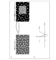
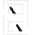
図6は、ヘッドマウントディスプレイ1から約1m未満の近距離に検出対象物21としての指が存在する場合、そのX軸方向の座標とY軸方向の座標とを求める原理を説明するための図である。
図6の(a)および図6の(b)は、赤外光照射部5から出射されたドットパターンが、それぞれ異なる位置にある指が存在する箇所のみで反射され、赤外光検出部6としての赤外光カメラによって得られた撮像パターンを図示している。なお、図6の(a)および図6の(b)においては、背景物は赤外光検出部6によって検出されない程、遠くに存在するものとする。
したがって、指が存在する箇所に相当するドットパターンが存在する箇所のX軸方向(図中左右方向)の座標とY軸方向(図中上下方向)の座標とを求めればよい。
また、ヘッドマウントディスプレイ1から約1m以上の遠距離に存在する検出対象物21についても、同様にX軸方向の座標とY軸方向の座標とを求めることができる。
GPU27においては、CPU26から送られた上記遠距離の画像データとして分離されたドットパターンからなる奥行き画像データに基づいて、検出対象物21の輪郭線を示す画像を作成し、ディスプレイコントローラ29・30に供給し、ヘッドマウントディスプレイ1の右眼用画像表示部3および左眼用画像表示部4に背景画像として表示するようになっている。
検出対象物21の輪郭線を示す画像の作成においては、上記遠距離の画像データとして分離されたドットパターンからなる奥行き画像データは、離散値であるため、輪郭線を得るためには、上記離散値の離散の程度がステップ分解能以下である必要があるが、上記離散値の離散の程度がステップ分解能より大きい場合には、線形補間などを用いて、等距離になる輪郭線を得ることができる。
同様に、GPU27においては、CPU26から送られた上記近距離の画像データとして分離されたドットパターンからなる奥行き画像データに基づいて、検出対象物21である例えば、指の輪郭線を示す画像を作成し、再び、CPU26に送る。
そして、図7の(a)に図示されているように、CPU26は、メモリ31に格納されている指の骨格モデル21bに関するデータを上記指の輪郭線21cを示す画像にフィッティングし、指先の先端部分21aのX,Y、Z座標を求めることができる。
このように、指の骨格モデルを用いて、指先の先端部分のX,Y、Z座標を求めることにより、ヘッドマウントディスプレイ1において、より精度よく入力操作を行うことができる。なお、上記入力操作の一例については、後述する。
また、通信部33を介して取得した例えば、電子書籍などのコンテンツ画像は、CPU26を介してGPU27に送られ、GPU27において3D用の画像(右眼用画像および左眼用画像)が作成され、上記3D用の画像は、必要に応じて3Dメモリ28に格納された後、ディスプレイコントローラ29・30に供給されるようになっている。
以上のようにして、電子書籍などのコンテンツ画像をヘッドマウントディスプレイ1の使用者に立体画像(3D画像)として認識させることができる。
なお、電子書籍などのコンテンツ画像は、予めメモリ31に格納されているもの用いることもできる。
そして、図2に図示されているように、制御ユニット7には、CPU26と接続されており、電源スイッチやモード設定スイッチやその他の操作スイッチなどからなるSW部32(スイッチ部)と、CPU26と接続されている各種のソフトウェア類が格納されているソフトウェア貯蔵部38とが備えられている。
ソフトウェア貯蔵部38には、例えば、座標検出アルゴリズムなどが格納されている。
Audio部34は、通信部33を介して取得された音声データやヘッドマウントディスプレイ1に備えられたマイク(未図示)から入力された音声データを解析し、イヤホン8・9から出力するようになっている。
なお、電源供給部35は、制御ユニット7の各パーツに電源を供給するようになっている。
図7の(b)、図7の(c)および図7の(d)は、具体的な入力操作の一例を示す図である。
上記入力操作は、検出対象物21である例えば、指の先端座標の時間的変化パターンによって何種類かのジェスチャー認識を行うことにより実現できる。
図7の(b)は、コンテンツ画像として表示される仮想ブックの左上の付近で、指を左から右に動かせば、ページ進みジェスチャーとして認識され、仮想ブックのページがめくられる画像とともに、新しいページの画像が表示される一方、仮想ブックの右上の付近で、指を右から左へ動かすとページ戻しジェスチャーとして認識され、仮想電子ブックのページがめくられる画像とともに、以前のページの画像が表示される場合を図示している。
図7の(c)は、仮想ブックの真ん中付近で指を左から右へ動かすと仮想ブックが、初期背景座標の中で右へ移動する場合を図示している。
また、図7の(d)は、仮想ブックの上で、親指と人指し指を広げるように操作すると、親指と人指し指の中心の座標を中心にして仮想ブックそのものの大きさが大きくなる場合を図示している。
図示してないが、仮想ブックの上で、逆に親指と人指し指の距離を縮めると、仮想ブックは小さくなる。
上記入力操作は、これらに限定されることはなく、例えば、図8に示すように、検出対象物21である例えば、指の仮想ブックへのタッチ有無で入力操作を行うこともできる。
図8においては、検出対象物21である指が仮想ブックに近づく方向がZ軸方向である。
図9は、検出対象物21である指の先端のZ軸方向の座標に基づいて、指の仮想ブックへのタッチの有無を判定する方式の一例を示す図である。
図9の(a)は、検出対象物21である指の先端のZ軸方向の座標の時間的変化を示しており、Z軸方向の座標が所定の閾値以上である場合、指の仮想ブックへのタッチがあったと判定する方式を示している。
すなわち、指の先端がヘッドマウントディスプレイ1から閾値以上離れると、タッチがあったと判定する方式である。
なお、上記閾値は、上記仮想ブックを表示するZ軸方向の座標に基づいて、適宜設定することができる。
また、図9の(b)は、検出対象物21である指の先端のZ軸方向の座標の時間的変化を示しており、Z軸方向の座標が、設定した2つの閾値1と閾値2との間に所定時間の間
、存在する場合、指の仮想ブックへのタッチがあったと判定する方式を示している。
、存在する場合、指の仮想ブックへのタッチがあったと判定する方式を示している。
また、図9の(c)は、検出対象物21である指の先端のZ軸方向の座標を時間で微分した値が所定時間の間、所定の閾値以上である場合、指の仮想ブックへのタッチがあったと判定する方式を示している。
なお、ヘッドマウントディスプレイ1において、指の仮想ブックへのタッチの有無を判定する方式は、図9に示した方式に限定されることはなく、例えば、図9の(a)と図9の(c)とを組合わせた方式や図9の(b)と図9の(c)とを組合わせた方式を用いてもよい。
また、以下で説明するように、CPU26においては、nフレーム間に変化したヘッドマウントディスプレイ1の使用者の姿勢変化量を算出することにより、コンテンツ画像である仮想ブックを上記使用者の姿勢変化量に応じて表示させることができる。
XYZ軸の回転をθ、φ、γ、XYZ軸の平行移動をX,Y,Zとすると、各回転行列Rx(θ)、Ry(φ)およびRz(γ)と平行移動行列T(X,Y,Z)とは、下記式(6)~式(9)で表すことができる。



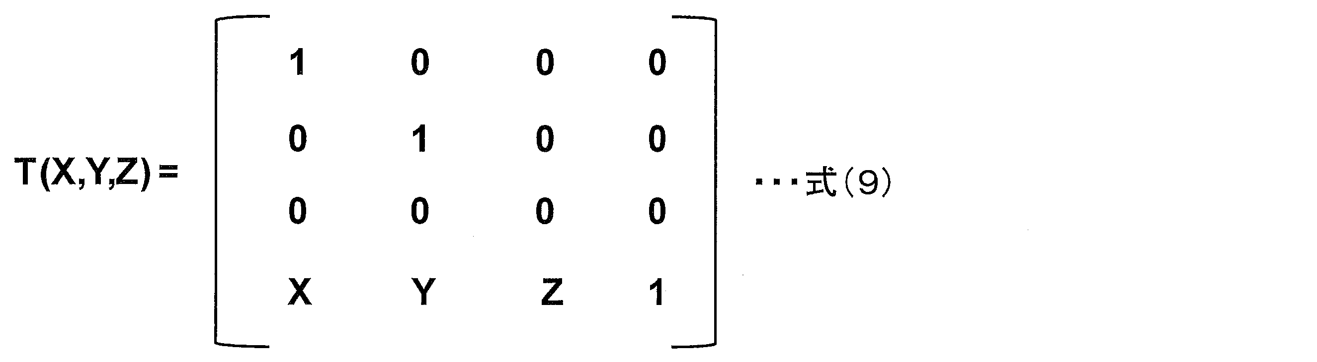
下記式(10)において、初期の背景画像〔xyz〕は(xi,yi,z0(xi,yi))で表現され、nフレーム後の背景画像〔x’y’z’〕は(xi,yi,zn(xi,yi))で表現されるので、nフレーム間に変化したヘッドマウントディスプレイ1の使用者の姿勢変化量Rx(θ)Ry(φ)Rz(γ)T(X,Y,Z)を逆算することができる。

そして、nフレーム間に変化したヘッドマウントディスプレイ1の使用者の姿勢変化量Rx(θ)Ry(φ)Rz(γ)T(X,Y,Z)の逆行列をM(θ,φ,γ,X,Y,Z)とすると、下記式(11)が成り立つ。

ヘッドマウントディスプレイ1の右眼用画像表示部3および左眼用画像表示部4に、所定の背景画像、例えば、初期の背景画像が常に表示される場合、コンテンツ画像である仮想ブックの初期座標値を上記使用者の姿勢変化量Rx(θ)Ry(φ)Rz(γ)T(X,Y,Z)分、変換させて表示することにより、上記仮想ブックのみが上記使用者の姿勢が変化した分だけついてくるモード(ツール装着モード)を実現することができる。
一方で、ヘッドマウントディスプレイ1の右眼用画像表示部3および左眼用画像表示部4に、上記使用者の姿勢変化に応じて、次々と変わる背景画像が表示される場合、上記使用者の姿勢変化量Rx(θ)Ry(φ)Rz(γ)T(X,Y,Z)の逆行列をM(θ,φ,γ,X,Y,Z)を用いて、コンテンツ画像である仮想ブックのみを初期座標値に固定して表示させることができる。したがって、上記使用者の姿勢変化に応じて、背景画像が次々と変わるが、コンテンツ画像である仮想ブックは、所定の位置に置かれているように表示されるモード(MRモード;Mixed Realityモード)を実現することができる。
ヘッドマウントディスプレイ1においては、使用者がツール装着モードとMRモードとを選択できるようにしている。
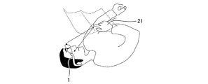
図10に図示されているように、ヘッドマウントディスプレイ1を装着した使用者は、寝ころんで楽な姿勢で所定情報の画像を見ることができるとともに、寝室などの暗いところにおいても、入力操作を行うことができる。
〔実施の形態2〕
次に、図11から図20に基づいて、本発明の第2の実施形態について説明する。本実施の形態のヘッドマウントディスプレイ1aには、よりリアリティ性を向上させるために、背景画像をカラー画像で取り込むための右眼用撮像装置36と左眼用撮像装置37とが備えられている点において、実施の形態1とは異なっており、その他の構成については実施の形態1において説明したとおりである。説明の便宜上、上記の実施の形態1の図面に示した部材と同じ機能を有する部材については、同じ符号を付し、その説明を省略する。
次に、図11から図20に基づいて、本発明の第2の実施形態について説明する。本実施の形態のヘッドマウントディスプレイ1aには、よりリアリティ性を向上させるために、背景画像をカラー画像で取り込むための右眼用撮像装置36と左眼用撮像装置37とが備えられている点において、実施の形態1とは異なっており、その他の構成については実施の形態1において説明したとおりである。説明の便宜上、上記の実施の形態1の図面に示した部材と同じ機能を有する部材については、同じ符号を付し、その説明を省略する。
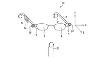
図11は、右眼用撮像装置36(カラーカメラ)と左眼用撮像装置37(カラーカメラ)とを備えたヘッドマウントディスプレイ1aの概略構成を示す図である。
図示されているように、ヘッドマウントディスプレイ1aの装着部2であり、赤外光検出部6と隣接する箇所には右眼用撮像装置36が備えられており、赤外光照射部5と隣接する箇所には左眼用撮像装置37が備えられている。
そして、右眼用撮像装置36と左眼用撮像装置37とは、両眼視差を有する右眼用画像と左眼用画像とを取り込めるように、所定距離を離して設けられている。
図12は、ヘッドマウントディスプレイ1aの各部分を説明するための図である。
図示されているように、右眼用撮像装置36から取り込まれた右眼用のカラー画像と左眼用撮像装置37から取り込まれた左眼用のカラー画像とは、制御ユニット7a内の3Dメモリ28に格納され、CPU26は、これらの右眼用のカラー画像と左眼用のカラー画像とから、詳しくは後述する位相限定相関法を用いて、これらの右眼用のカラー画像と左眼用のカラー画像との奥行き情報を算出するようになっている。
そして、GPU27においては、CPU26で算出した上記背景画像の奥行き情報を基にして、3D用画像として、GPU27で作成された仮想ブックや仮想神殿などのコンテンツ画像の右眼用のカラー画像が上記背景画像の右眼用のカラー画像より手前側に位置するように、コンテンツ画像の右眼用のカラー画像と上記背景画像の右眼用のカラー画像とを透明合成させた右眼用のカラー画像を作成し、ディスプレイコントローラ29aに供給するようになっている。
同様に、GPU27においては、CPU26で算出した上記背景画像の奥行き情報を基にして、3D用画像として、GPU27で作成された仮想ブックや仮想神殿などのコンテンツ画像の左眼用のカラー画像が上記背景画像の左眼用のカラー画像より手前側に位置するように、コンテンツ画像の左眼用のカラー画像と上記背景画像の左眼用のカラー画像とを透明合成させた左眼用のカラー画像を作成し、ディスプレイコントローラ30aに供給するようになっている。
したがって、ヘッドマウントディスプレイ1aの使用者には、仮想ブックや仮想神殿などのコンテンツ画像が、上記背景画像の手前に位置するように認識させることができる。
なお、上記透明合成法以外に、上記コンテンツ画像と上記背景画像とが重なっている部分では、上記コンテンツ画像のみが優先的に見えるようにしてもよい。
図13は、ヘッドマウントディスプレイ1aにおいて、MRモードを実現した場合の一例を示している。
図13の(a)は、右眼用撮像装置36および左眼用撮像装置37から取り込まれ、ヘッドマウントディスプレイ1aの使用者に認識される3D用の背景画像のカラー画像を示しており、この3D用の背景画像のカラー画像は、上記使用者の姿勢変化に応じて次々と変わる。
図13の(b)は、上記3D用の背景画像のカラー画像上に、コンテンツ画像である仮想神殿を手前側に重ねて表示させ、上記コンテンツ画像のみが優先的に見えるようにした場合を示している。
上記実施の形態1で既に説明したように、MRモードにおいては、上記使用者の姿勢変化に応じて、背景画像が次々と変わるが、コンテンツ画像である仮想神殿は、所定の位置に置かれているように表示させることができる。
したがって、このようなモードによれば、周囲のリアルタイムな状況を知りながら、仮想コンテンツを楽しむことができる。
一方、図14は、ヘッドマウントディスプレイ1aにおいて、ツール装着モードを実現した場合の一例を示している。
図14の(a)および図14の(b)に図示されているように、ヘッドマウントディスプレイ1aの使用者の姿勢が変化しても、上記使用者に認識される背景画像は、常に同じであるが、コンテンツ画像である仮想ブックのみが上記使用者の姿勢が変化した分だけついてくるようにすることができる。
なお、図14の(a)および図14の(b)においては、上記背景画像の手前側に、上記コンテンツ画像を透明合成させた場合を示しており、上記コンテンツ画像を通して、後ろの背景画像をある程度見ることができるようになっている。
ヘッドマウントディスプレイ1aにおいては、使用者がMRモードとツール装着モードとを選択できるようにしているため、使い勝手がよい。
(位置限定相関法)
以下、図15から図20に基づいて、右眼用撮像装置36から取り込まれた右眼用のカラー画像と左眼用撮像装置37から取り込まれた左眼用のカラー画像とから、より精度の高い奥行き情報を算出するために本実施の形態において用いられる位相限定相関法について説明する。
(位置限定相関法)
以下、図15から図20に基づいて、右眼用撮像装置36から取り込まれた右眼用のカラー画像と左眼用撮像装置37から取り込まれた左眼用のカラー画像とから、より精度の高い奥行き情報を算出するために本実施の形態において用いられる位相限定相関法について説明する。
なお、本実施の形態においては、より精度の高い奥行き情報を算出するため位相限定相関法を用いているが、この他の相関法を用いてもよいのはもちろんである。
図15は、ある同一フレームにおいて、右眼用撮像装置36から取り込まれた右眼用のカラー画像f(n1,n2)と左眼用撮像装置37から取り込まれた左眼用のカラー画像g(n1,n2)との大きさを示す図である。
右眼用のカラー画像f(n1,n2)と左眼用のカラー画像g(n1,n2)とは、微小に位置ずれした同一画像であり、その大きさは図示されているようにN1×N2である。
そして、定式化の便宜上、離散空間のインデックスをn1=-M1,・・・,M1およびn2=-M2,・・・,M2とし、画像の大きさをN1=2M1+1およびN2=2M2+1とすると、画像f(n1,n2)および画像g(n1,n2)を2次元離散フーリエ変換したF(k1,k2)およびG(k1,k2)を、下記式(12)および下記式(13)のように得ることができる。


上記式(12)および上記式(13)においては、k1=-M1,・・・,M1,k2=-M2,・・・,M2,WN1=e-j2π/N1,WN2=e-j2π/N2である。
上記式(12)において、AF(k1,k2)は、画像f(n1,n2)の振幅成分であり、ejθf(k1,k2)は、信号の位相成分であり、上記式(13)において、AG(k1,k2)は、画像g(n1,n2)の振幅成分であり、ejθg(k1,k2)は、信号の位相成分である。
そして、上記各画像のフーリエ変換の各周波数での絶対値で正規化した相関値R(k1,k2)は、下記式(14)のように定義される。
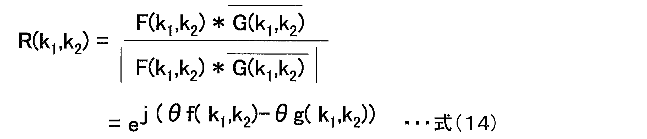
上記式(14)は、画像f(n1,n2)および画像g(n1,n2)が同じ場合には、全て1(完全相関)となる。
上記式(14)を逆フーリエ変換して下記式(15)で表される位相限定相関関数r(n1,n2)を得ることができる。

一方、連続空間で定義された画像の場合においては、以下のようにして位相限定相関関数を得ることができる。
連続空間で定義された元画像をSc(x1,x2)で表した場合、上記連続空間でδ1,δ2だけシフトした画像はSc(x1-δ1,x2-δ2)で表される。
元画像の離散サンプルを右眼用撮像装置36から取り込まれた右眼用のカラー画像f(n1,n2)とし、シフトした画像を左眼用撮像装置37から取り込まれた左眼用のカラー画像g(n1,n2)とすると、画像f(n1,n2)は、下記式(16)のように定義され、画像g(n1,n2)は、下記式(17)のように定義される。


そして、このときの位相限定相関関数は、下記式(18)となる。

なお、上記式(18)における位相限定相関法では、帯域制限により1≦αとなる。
また、画像サイズN1,N2が十分に大きい場合は、位相限定相関関数は、下記式(19)に示すように近似できる。

また、画像f(n1,n2)および画像g(n1,n2)を2次元離散フーリエ変換したF(k1,k2)およびG(k1,k2)は、画像が循環することを仮定しているので、画像端で不連続となり、折り返し歪が発生する。
したがって、本実施の形態においては、上記折り返し歪の影響を低減するため、下記式(20)に示すようなハニング窓関数を画像f(n1,n2)および画像g(n1,n2)に乗じた。

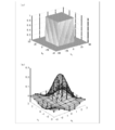
図16は、位相限定相関法に基づく画像マッチングを行う際に用いられるハニング窓の1例であり、折り返し歪の影響を低減するための空間フィルタを示す。
図16は、上記式(20)を視覚化したもので、そのオフセットは(0,0)が(16,16)に対応している。
なお、右眼用撮像装置36や左眼用撮像装置37などのカメラで撮影した自然画像では、低周波数領域に比べて高周波数領域におけるS/N比が低いことが予測されるため、本実施の形態においては、重み付け関数として、方形型の低域通過フィルタを用いることで、信頼性の低い高周波成分を除去し、高精度化を実現している。
下記式(21)に示すように、重み付け関数としての方形型の低域通過フィルタH(k1,k2)は、k1が0~U1であり、k2が0~U2であるときには1となり、その他のときには0となる。
なお、U1およびU2はそれぞれ0≦U1≦M1および0≦U2≦M2を満たす整数である。

そして、上記式(19)に方形型の低域通過フィルタH(k1,k2)を適用すると、
下記式(22)のように表される。
下記式(22)のように表される。

上記式(22)において、V1=2U1+1で、V2=2U2+1である。
なお、図17の(a)は、重み付け関数としての方形型の低域通過フィルタH(k1,k2)のスペクトルを示しており、図17の(b)は、これに対応する位相限定相関関数を示している。
そして、上記式(22)に示す位相限定相関関数を1次元相関ピークモデルに基づく評価式(Peak Evaluation Formula:PEF)で書き直すと下記式(23)となる。

図18は、上記式(23)に示す位相限定相関関数と座標点との関係を示す図である。
図示されているように、点n=pに着目し、さらにこの点pから±d(dは自然数)だけ離れた点n=p+dおよびn=p-dを考えると、この3点における位相限定相関関数の値r(n-d)、r(n)、r(n+d)の間には、下記式(24)の関係が成り立つ。

そして、サブピクセルの移動量δは下記式(25)となる。
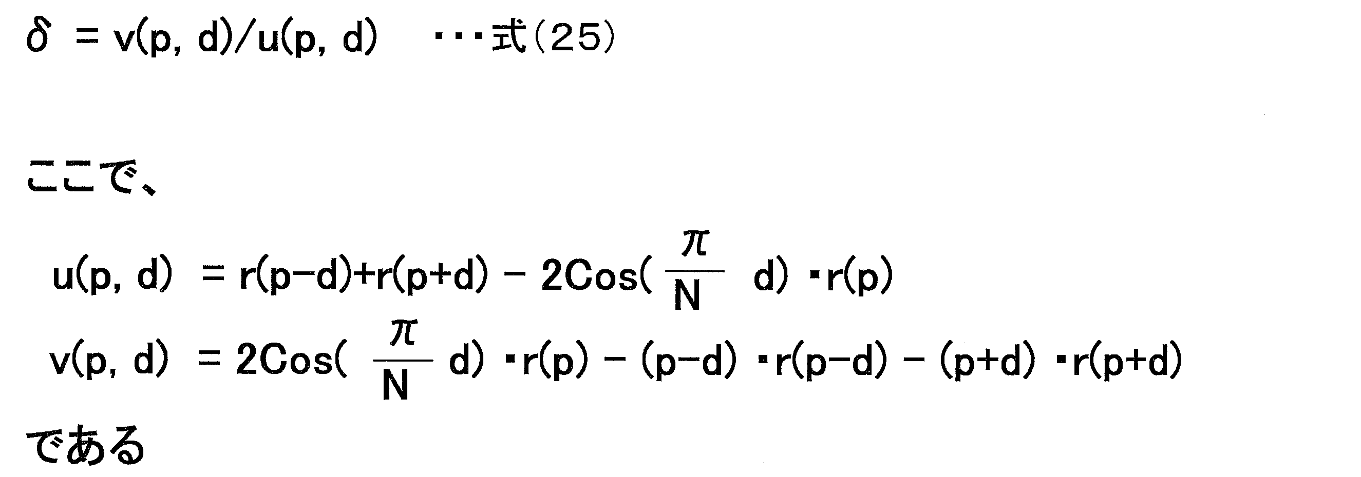
以下、複数(I組)の3点組より最小2乗法にて、ピーク位置を算出する方法について説明する。
I組の3点組を下記式(26)とすると、L個の方程式が得られる。

そして、下記式(27)に示すサブピクセルの移動量δの最適値を求めるためには、下記式(28)に示す2乗誤差を最小にすればよい。


上記式(28)をδで変分して0とおくと、下記式(29)を得ることができる。

図19の(a)から図19の(d)は、上記位相限定相関関数の1番目のピーク中心よりサブピクセルの移動量δを推定する方法を示す図であり、図20の(a)から図20の(d)は、上記位相限定相関関数の2番目のピーク中心よりサブピクセルの移動量δを推定する方法を示す図である。
以下、本実施の形態において、制御ユニット7a内で行われるサブピクセルの移動量δを推定する方法について具体的に説明する。
本実施の形態においては、制御ユニット7a内のCPU28で、少し位置ずれした画像f(n1,n2)と画像g(n1,n2)とに、上記式(20)に示すハニング窓関数をかけて、画像fw(n1,n2)と画像gw(n1,n2)とを生成する。
そして、画像fw(n1,n2)と画像gw(n1,n2)とをフーリエ変換し、上記式(12)に示すF(k1,k2)と、上記式(13)に示すG(k1,k2)と、を求める。
それから、上記式(14)に基づいて、F(k1,k2)とG(k1,k2)との係数の絶対値を正規化してR(k1,k2)を生成する。
そして、R(k1,k2)を逆フーリエ変換して、位相限定相関関数r(n1,n2)を得て、図19に図示されているように、位相限定相関関数r(n1,n2)の1番目のピークの位置を求めp1に対応させ、図20に図示されているように、位相限定相関関数r(n1,n2)の2番目のピークの位置を求めpl+1に対応させる。
それから、図19におけるd1,d2,d3・・・dlおよび図20におけるdl+1,dl+2,dl+3・・・d2lをそれぞれ1,2,3・・・lとし、上記式(25)に基づいて、2l個のu(pi,di),v(pi,di)を求める。
最後に、上記式(29)に基づいて、U,Vベクトルを定義し、サブピクセルの移動量δを求め、奥行き情報を算出する。
本発明のヘッドマウントディスプレイにおいては、上記制御部は、上記第3の軸方向の座標値が所定値未満である上記検出対象物の座標値の所定期間の間の変化に基づいて、入力操作の種類を判断することが好ましい。
上記構成によれば、上記制御部は、上記第3の軸方向の座標値が所定値未満である上記検出対象物、すなわち、上記ヘッドマウントディスプレイから比較的近距離に存在する上記検出対象物は、入力操作を行うための検出対象物と判断し、このような検出対象物の座標値の所定期間の間の変化に基づいて、入力操作の種類を判断するようになっている。
したがって、入力操作を行うことができるヘッドマウントディスプレイを実現することができる。
本発明のヘッドマウントディスプレイにおいては、上記第3の軸方向の座標値が所定値未満である上記検出対象物は上記使用者の指であって、上記指の座標値は、上記指によって反射された所定パターンに基づいて作成された上記指の輪郭線を示す画像に、指の骨格画像をフィッティングさせて得られる画像における指先の座標値であることが好ましい。
上記構成によれば、上記使用者が、特別な入力手段を用いずに、指を用いて入力操作を行う場合においても、精度の高い入力操作を行うことができる。
本発明のヘッドマウントディスプレイにおいて、上記制御部は、第1の時期に上記赤外光検出部によって得られた上記第3の軸方向の座標値が所定値以上である上記検出対象物によって反射された所定パターンに基づいて作成された上記検出対象物の輪郭線を示す画像を、背景画像として上記表示部に表示するとともに、上記第1の時期に上記赤外光検出部によって得られた所定パターンと、所定期間後である第2の時期に得られた上記検出対象物によって反射された所定パターンとから上記使用者の姿勢変化量を算出し、上記表示部にコンテンツ画像を上記姿勢変化量分移動させて表示してもよい。
上記構成によれば、上記制御部は、第1の時期に上記赤外光検出部によって得られた上記第3の軸方向の座標値が所定値以上である、すなわち、上記ヘッドマウントディスプレイから比較的遠距離に存在する上記検出対象物は、背景として認識するようになっている。
そして、上記第1の時期に上記赤外光検出部によって得られた上記第3の軸方向の座標値が所定値以上である上記検出対象物によって反射された所定パターンに基づいて作成された上記検出対象物の輪郭線を示す画像を、背景画像として上記表示部に常に表示するようになっている。
したがって、上記使用者が、例えば、首を動かしたりするなど姿勢を変化させても、上記使用者は、常に同じ背景画像を見ることができる。
そして、上記第1の時期に上記赤外光検出部によって得られた所定パターンと、所定期間後である第2の時期に得られた上記検出対象物によって反射された所定パターンとから上記使用者の姿勢変化量を算出し、上記表示部に表示するコンテンツ画像のみを上記姿勢変化量分移動させて表示することができる。
上記構成によれば、使用者の姿勢が変わっても、上記表示部には常に同じ背景画像が表示され、上記表示部に表示されるコンテンツ画像のみが上記使用者の姿勢変化量に応じて、位置を変えて表示されるモードを実現できる。
本発明のヘッドマウントディスプレイにおいて、上記制御部は、上記赤外光検出部によって得られた上記第3の軸方向の座標値が所定値以上である上記検出対象物によって反射された所定パターンに基づいて作成された上記検出対象物の輪郭線を示す画像を、順次的に背景画像として上記表示部に表示するとともに、第1の時期に上記赤外光検出部によって得られた所定パターンと、所定期間後である第2の時期に得られた上記検出対象物によって反射された所定パターンとから上記使用者の姿勢変化量を算出し、上記表示部にコンテンツ画像を上記姿勢変化量とは逆方向の変化量分移動させて表示させてもよい。
上記使用者が、ヘッドマウントディスプレイを装着していない場合においては、上記使用者の姿勢の変化に応じて、上記使用者の目に見える背景は次々と変わる。
上記構成によれば、ヘッドマウントディスプレイを装着していても、装着していない場合のように、上記使用者の姿勢の変化に応じて、上記使用者の目に上記表示部を介して見える背景は次々と変わるようにすることができる。
一方、上記表示部に表示されるコンテンツ画像は、上記使用者の姿勢変化量とは逆方向の変化量分移動させて表示されるようになっているため、上記コンテンツ画像は、次々と変わる背景画像の所定箇所に固定されているようにすることができる。
上記構成によれば、上記使用者の姿勢の変化に応じて、次々と変わる背景画像に対して、上記コンテンツ画像を次々と変わる上記背景画像の所定箇所に固定させて表示されるモードを実現できる。
本発明のヘッドマウントディスプレイにおいて、上記表示部には、左眼用画像を表示する左眼用画像表示部と、右眼用画像を表示する右眼用画像表示部と、が備えられており、上記装着部には、上記背景画像の左眼用画像を取り込む左眼用撮像装置と上記背景画像の右眼用画像を取り込む右眼用撮像装置とが、所定間隔を有して備えられており、上記制御部は、上記背景画像および上記コンテンツ画像の左眼用画像を上記左眼用画像表示部に、上記背景画像および上記コンテンツ画像の右眼用画像を上記右眼用画像表示部に、それぞれ所定間隔で交互に表示する構成であってもよい。
上記構成によれば、上記背景画像および上記コンテンツ画像を上記使用者に、奥行き感を有する立体画像で認識させることができるので、さらにリアル感を増大させたヘッドマウントディスプレイを実現することができる。
本発明のヘッドマウントディスプレイにおいて、上記制御部は、上記背景画像の左眼用画像と右眼用画像とから相関法によって、奥行き情報を求め、上記奥行き情報に基づいて、上記背景画像と上記コンテンツ画像との合成を行うことが好ましい。
本発明のヘッドマウントディスプレイにおいて、上記相関法は、位相限定相関法であることが好ましい。
上記構成によれば、例えば、位相限定相関法などの相関法を用いて求めた上記背景画像の奥行き情報に基づいて、上記背景画像と上記コンテンツ画像との合成画像を生成することができるので、リアル感を増大させたヘッドマウントディスプレイを実現することができる。
また、上記相関法として、位相限定相関法を用いた場合には、より精度の高い奥行き情報を得ることができる。
本発明のヘッドマウントディスプレイにおいて、上記背景画像と上記コンテンツ画像とは、上記使用者が上記コンテンツ画像を介して、上記背景画像を見ることができるように合成されていることが好ましい。
上記構成によれば、上記使用者が上記コンテンツ画像を介して、上記背景画像を見ることができるので、上記使用者は上記コンテンツ画像と上記背景画像とを同時に楽しむことができる。
本発明のヘッドマウントディスプレイにおいて、上記左眼用撮像装置と上記右眼用撮像装置とは、カラー画像を取り込むことができるカラー撮像装置であることが好ましい。
上記構成によれば、さらにリアル感を増大させたヘッドマウントディスプレイを実現することができる。
本発明のヘッドマウントディスプレイの上記制御部は、上記第3の軸方向の座標値が所定値未満である上記検出対象物の上記第1の軸方向および上記第2の軸方向の座標値の所定期間の間の変化に基づいて、上記表示部に表示されるコンテンツ画像に対して、拡大、縮小、移動および画像変換の何れか1つの操作を行うかを選定し、上記検出対象物の上記第3の軸方向の座標値の所定期間の間の変化に基づいて、上記検出対象物の上記表示部に表示されるコンテンツ画像へのタッチ有無を判断し、タッチ有と判断された場合に、上記表示部に表示されるコンテンツ画像に対して上記操作を行った後に表示する構成であってもよい。
上記構成によれば、上記制御部は、上記第3の軸方向の座標値が所定値未満である上記検出対象物の上記第1の軸方向および上記第2の軸方向の座標値の所定期間の間の変化に基づいて、上記表示部に表示されるコンテンツ画像に対して、拡大、縮小、移動および画像変換などを行う操作の種類を決定し、上記検出対象物の上記第3の軸方向の座標値の所定期間の間の変化に基づいて、上記表示部に表示されるコンテンツ画像に対して上記操作を行うかを決定するようになっている。
したがって、比較的精度の高い入力操作を行うことができるヘッドマウントディスプレイを実現することができる。
本発明は上記した各実施の形態に限定されるものではなく、請求項に示した範囲で種々の変更が可能であり、異なる実施の形態にそれぞれ開示された技術的手段を適宜組み合わせて得られる実施の形態についても本発明の技術的範囲に含まれる。
本発明は、ヘッドマウントディスプレイなどに好適に用いることができる。
1、1a ヘッドマウントディスプレイ
2 装着部
3 右眼用画像表示部
4 左眼用画像表示部
5 赤外光照射部
6 赤外光検出部
7 制御ユニット(制御部)
8 右耳用イヤホン
9 左耳用イヤホン
10a、10b 白色LED
11a、11b 集光レンズ
12a、12b 液晶表示パネル
13a、13b プリズム
14a、14b レンズ
15 赤外光LED
16 拡散板
17 マイクロレンズアレイ部
18 投射レンズ
19 CCD
20 集光レンズ
21 検出対象物
22 相関器
23、31 メモリ
24 奥行き情報復元部
25 LED駆動回路
26 CPU
27 GPU
28 3Dメモリ
29、29a、30、30a ディスプレイコントローラ
32 SW部
33 通信部
34 Audio部
35 電源供給部
36 右眼用撮像装置
37 左眼用撮像装置
38 ソフトウェア貯蔵部
2 装着部
3 右眼用画像表示部
4 左眼用画像表示部
5 赤外光照射部
6 赤外光検出部
7 制御ユニット(制御部)
8 右耳用イヤホン
9 左耳用イヤホン
10a、10b 白色LED
11a、11b 集光レンズ
12a、12b 液晶表示パネル
13a、13b プリズム
14a、14b レンズ
15 赤外光LED
16 拡散板
17 マイクロレンズアレイ部
18 投射レンズ
19 CCD
20 集光レンズ
21 検出対象物
22 相関器
23、31 メモリ
24 奥行き情報復元部
25 LED駆動回路
26 CPU
27 GPU
28 3Dメモリ
29、29a、30、30a ディスプレイコントローラ
32 SW部
33 通信部
34 Audio部
35 電源供給部
36 右眼用撮像装置
37 左眼用撮像装置
38 ソフトウェア貯蔵部
Claims (11)
- 使用者に画像を認識させる表示部を備え、検出対象物の3次元座標を算出できるヘッドマウントディスプレイであって、
上記使用者が頭部に装着するための装着部には、上記検出対象物に所定パターンの赤外光を照射する赤外光照射部と、上記検出対象物によって反射された上記赤外光を検出する赤外光検出部と、が所定間隔を有して備えられており、
制御部には、上記3次元座標の算出部が備えられており、
上記算出部は、上記赤外光検出部によって得られた上記検出対象物によって反射された所定パターンから、互いに直交する第1の軸方向および第2の軸方向の座標値を算出し、上記検出対象物に照射される所定パターンと上記赤外光検出部によって得られた上記検出対象物によって反射された所定パターンとのずれ量から、上記第1の軸方向および上記第2の軸方向と直交し、かつ、上記使用者の視線方向である第3の軸方向の座標値を算出することを特徴とするヘッドマウントディスプレイ。 - 上記制御部は、上記第3の軸方向の座標値が所定値未満である上記検出対象物の座標値の所定期間の間の変化に基づいて、入力操作の種類を判断することを特徴とする請求項1に記載のヘッドマウントディスプレイ。
- 上記第3の軸方向の座標値が所定値未満である上記検出対象物は上記使用者の指であって、
上記指の座標値は、上記指によって反射された所定パターンに基づいて作成された上記指の輪郭線を示す画像に、指の骨格画像をフィッティングさせて得られる画像における指先の座標値であることを特徴とする請求項2に記載のヘッドマウントディスプレイ。 - 上記制御部は、第1の時期に上記赤外光検出部によって得られた上記第3の軸方向の座標値が所定値以上である上記検出対象物によって反射された所定パターンに基づいて作成された上記検出対象物の輪郭線を示す画像を、背景画像として上記表示部に表示するとともに、
上記第1の時期に上記赤外光検出部によって得られた所定パターンと、所定期間後である第2の時期に得られた上記検出対象物によって反射された所定パターンとから上記使用者の姿勢変化量を算出し、上記表示部にコンテンツ画像を上記姿勢変化量分移動させて表示することを特徴とする請求項1から3の何れか1項に記載のヘッドマウントディスプレイ。 - 上記制御部は、上記赤外光検出部によって得られた上記第3の軸方向の座標値が所定値以上である上記検出対象物によって反射された所定パターンに基づいて作成された上記検出対象物の輪郭線を示す画像を、順次的に背景画像として上記表示部に表示するとともに、
第1の時期に上記赤外光検出部によって得られた所定パターンと、所定期間後である第2の時期に得られた上記検出対象物によって反射された所定パターンとから上記使用者の姿勢変化量を算出し、上記表示部にコンテンツ画像を上記姿勢変化量とは逆方向の変化量分移動させて表示することを特徴とする請求項1から3の何れか1項に記載のヘッドマウントディスプレイ。 - 上記表示部には、左眼用画像を表示する左眼用画像表示部と、右眼用画像を表示する右眼用画像表示部と、が備えられており、
上記装着部には、上記背景画像の左眼用画像を取り込む左眼用撮像装置と上記背景画像の右眼用画像を取り込む右眼用撮像装置とが、所定間隔を有して備えられており、
上記制御部は、上記背景画像および上記コンテンツ画像の左眼用画像を上記左眼用画像表示部に、上記背景画像および上記コンテンツ画像の右眼用画像を上記右眼用画像表示部に、それぞれ所定間隔で交互に表示することを特徴とする請求項4または5に記載のヘッドマウントディスプレイ。 - 上記制御部は、上記背景画像の左眼用画像と右眼用画像とから相関法によって、奥行き情報を求め、上記奥行き情報に基づいて、上記背景画像と上記コンテンツ画像との合成を行うことを特徴とする請求項6に記載のヘッドマウントディスプレイ。
- 上記相関法は、位相限定相関法であることを特徴とする請求項7に記載のヘッドマウントディスプレイ。
- 上記背景画像と上記コンテンツ画像とは、上記使用者が上記コンテンツ画像を介して、上記背景画像を見ることができるように合成されていることを特徴とする請求項7または8に記載のヘッドマウントディスプレイ。
- 上記左眼用撮像装置と上記右眼用撮像装置とは、カラー画像を取り込むことができるカラー撮像装置であることを特徴とする請求項6から9の何れか1項に記載のヘッドマウントディスプレイ。
- 上記制御部は、上記第3の軸方向の座標値が所定値未満である上記検出対象物の上記第1の軸方向および上記第2の軸方向の座標値の所定期間の間の変化に基づいて、上記表示部に表示されるコンテンツ画像に対して、拡大、縮小、移動および画像変換の何れか1つの操作を行うかを選定し、上記検出対象物の上記第3の軸方向の座標値の所定期間の間の変化に基づいて、上記検出対象物の上記表示部に表示されるコンテンツ画像へのタッチ有無を判断し、タッチ有と判断された場合に、上記表示部に表示されるコンテンツ画像に対して上記操作を行った後に表示することを特徴とする請求項2または3に記載のヘッドマウントディスプレイ。
Priority Applications (1)
| Application Number | Priority Date | Filing Date | Title |
|---|---|---|---|
| US14/113,402 US9024872B2 (en) | 2011-04-28 | 2012-04-23 | Head-mounted display |
Applications Claiming Priority (2)
| Application Number | Priority Date | Filing Date | Title |
|---|---|---|---|
| JP2011102372 | 2011-04-28 | ||
| JP2011-102372 | 2011-04-28 |
Publications (1)
| Publication Number | Publication Date |
|---|---|
| WO2012147702A1 true WO2012147702A1 (ja) | 2012-11-01 |
Family
ID=47072221
Family Applications (1)
| Application Number | Title | Priority Date | Filing Date |
|---|---|---|---|
| PCT/JP2012/060890 Ceased WO2012147702A1 (ja) | 2011-04-28 | 2012-04-23 | ヘッドマウントディスプレイ |
Country Status (2)
| Country | Link |
|---|---|
| US (1) | US9024872B2 (ja) |
| WO (1) | WO2012147702A1 (ja) |
Cited By (11)
| Publication number | Priority date | Publication date | Assignee | Title |
|---|---|---|---|---|
| JP2014093703A (ja) * | 2012-11-06 | 2014-05-19 | Sony Computer Entertainment Inc | ヘッドマウントディスプレイ、動き検出装置、動き検出方法、および映像提示システム |
| KR20140097657A (ko) * | 2013-01-28 | 2014-08-07 | 삼성전자주식회사 | 증강현실 콘텐츠 생성 방법 및 이를 구현하는 휴대단말장치 |
| WO2014076045A3 (en) * | 2012-11-19 | 2014-10-23 | Orangedental Gmbh & Co. Kg | Magnification loupe with display system |
| US20150264338A1 (en) * | 2012-09-27 | 2015-09-17 | Kyocera Corporation | Display device, control system, and control program |
| WO2017051564A1 (ja) * | 2015-09-25 | 2017-03-30 | 株式会社ソニー・インタラクティブエンタテインメント | 情報処理装置 |
| CN106569334A (zh) * | 2015-10-07 | 2017-04-19 | 财团法人资讯工业策进会 | 头戴式装置以及导览方法 |
| CN108139803A (zh) * | 2015-10-08 | 2018-06-08 | Pcms控股公司 | 用于动态显示器配置的自动校准的方法及系统 |
| JP2020503905A (ja) * | 2017-06-15 | 2020-02-06 | グーグル エルエルシー | 眼の特徴付けのための反射波面分析に基づくフレームレンダリングを有するニアアイディスプレイ |
| US11210858B2 (en) | 2015-08-24 | 2021-12-28 | Pcms Holdings, Inc. | Systems and methods for enhancing augmented reality experience with dynamic output mapping |
| US11741673B2 (en) | 2018-11-30 | 2023-08-29 | Interdigital Madison Patent Holdings, Sas | Method for mirroring 3D objects to light field displays |
| JP2024175123A (ja) * | 2019-06-28 | 2024-12-17 | キヤノン株式会社 | 撮像表示装置、およびウェアラブルデバイス |
Families Citing this family (32)
| Publication number | Priority date | Publication date | Assignee | Title |
|---|---|---|---|---|
| KR20140069660A (ko) * | 2012-11-29 | 2014-06-10 | 삼성전자주식회사 | 이미지 중첩 기반의 사용자 인터페이스 장치 및 방법 |
| US10061349B2 (en) * | 2012-12-06 | 2018-08-28 | Sandisk Technologies Llc | Head mountable camera system |
| US10110805B2 (en) * | 2012-12-06 | 2018-10-23 | Sandisk Technologies Llc | Head mountable camera system |
| US9286718B2 (en) * | 2013-09-27 | 2016-03-15 | Ortery Technologies, Inc. | Method using 3D geometry data for virtual reality image presentation and control in 3D space |
| US10360907B2 (en) | 2014-01-14 | 2019-07-23 | Toyota Motor Engineering & Manufacturing North America, Inc. | Smart necklace with stereo vision and onboard processing |
| US10024679B2 (en) | 2014-01-14 | 2018-07-17 | Toyota Motor Engineering & Manufacturing North America, Inc. | Smart necklace with stereo vision and onboard processing |
| US9578307B2 (en) * | 2014-01-14 | 2017-02-21 | Toyota Motor Engineering & Manufacturing North America, Inc. | Smart necklace with stereo vision and onboard processing |
| US9915545B2 (en) * | 2014-01-14 | 2018-03-13 | Toyota Motor Engineering & Manufacturing North America, Inc. | Smart necklace with stereo vision and onboard processing |
| US10248856B2 (en) | 2014-01-14 | 2019-04-02 | Toyota Motor Engineering & Manufacturing North America, Inc. | Smart necklace with stereo vision and onboard processing |
| FR3018119B1 (fr) * | 2014-02-28 | 2017-07-07 | Thales Sa | Systeme de visualisation de casque comportant des moyens d'affichage et de gestion de documentation |
| US10024678B2 (en) | 2014-09-17 | 2018-07-17 | Toyota Motor Engineering & Manufacturing North America, Inc. | Wearable clip for providing social and environmental awareness |
| US9922236B2 (en) | 2014-09-17 | 2018-03-20 | Toyota Motor Engineering & Manufacturing North America, Inc. | Wearable eyeglasses for providing social and environmental awareness |
| CN104581119B (zh) * | 2014-12-31 | 2017-06-13 | 青岛歌尔声学科技有限公司 | 一种3d图像的显示方法和一种头戴设备 |
| US9746921B2 (en) * | 2014-12-31 | 2017-08-29 | Sony Interactive Entertainment Inc. | Signal generation and detector systems and methods for determining positions of fingers of a user |
| US10490102B2 (en) | 2015-02-10 | 2019-11-26 | Toyota Motor Engineering & Manufacturing North America, Inc. | System and method for braille assistance |
| US9972216B2 (en) | 2015-03-20 | 2018-05-15 | Toyota Motor Engineering & Manufacturing North America, Inc. | System and method for storing and playback of information for blind users |
| US10401966B2 (en) * | 2015-05-15 | 2019-09-03 | Atheer, Inc. | Method and apparatus for applying free space input for surface constrained control |
| US9683834B2 (en) * | 2015-05-27 | 2017-06-20 | Intel Corporation | Adaptable depth sensing system |
| CN105183148A (zh) * | 2015-08-03 | 2015-12-23 | 众景视界(北京)科技有限公司 | 用于头戴式智能设备的平移检测方法及平移检测装置 |
| US10976808B2 (en) | 2015-11-17 | 2021-04-13 | Samsung Electronics Co., Ltd. | Body position sensitive virtual reality |
| US10024680B2 (en) | 2016-03-11 | 2018-07-17 | Toyota Motor Engineering & Manufacturing North America, Inc. | Step based guidance system |
| US9958275B2 (en) | 2016-05-31 | 2018-05-01 | Toyota Motor Engineering & Manufacturing North America, Inc. | System and method for wearable smart device communications |
| US10561519B2 (en) | 2016-07-20 | 2020-02-18 | Toyota Motor Engineering & Manufacturing North America, Inc. | Wearable computing device having a curved back to reduce pressure on vertebrae |
| US10432851B2 (en) | 2016-10-28 | 2019-10-01 | Toyota Motor Engineering & Manufacturing North America, Inc. | Wearable computing device for detecting photography |
| USD827143S1 (en) | 2016-11-07 | 2018-08-28 | Toyota Motor Engineering & Manufacturing North America, Inc. | Blind aid device |
| US10012505B2 (en) | 2016-11-11 | 2018-07-03 | Toyota Motor Engineering & Manufacturing North America, Inc. | Wearable system for providing walking directions |
| US10521669B2 (en) | 2016-11-14 | 2019-12-31 | Toyota Motor Engineering & Manufacturing North America, Inc. | System and method for providing guidance or feedback to a user |
| AU2018257776A1 (en) * | 2017-04-24 | 2019-10-31 | Magic Leap, Inc. | Tracking optical flow of backscattered laser speckle patterns |
| KR101947372B1 (ko) * | 2017-09-04 | 2019-05-08 | 주식회사 그루크리에이티브랩 | Hmd에 위치 보정 영상을 제공하는 방법 및 hmd에 위치 보정 영상을 표시하는 방법, 그리고 이를 이용한 위치 보정 영상을 표시하는 hmd |
| US10475196B2 (en) * | 2018-03-22 | 2019-11-12 | Microsoft Technology Licensing, Llc | Hybrid depth detection and movement detection |
| JP7243193B2 (ja) * | 2019-01-10 | 2023-03-22 | セイコーエプソン株式会社 | 表示システム、表示システムの制御方法、情報処理装置、及び情報処理装置の制御プログラム |
| USD1098242S1 (en) * | 2022-08-03 | 2025-10-14 | Asg Products, Llc | Electronic personal assistance glasses |
Citations (4)
| Publication number | Priority date | Publication date | Assignee | Title |
|---|---|---|---|---|
| JPH095666A (ja) * | 1995-06-15 | 1997-01-10 | Olympus Optical Co Ltd | 頭部装着型映像表示装置 |
| JP2009511897A (ja) * | 2005-10-11 | 2009-03-19 | プライム センス リミティド | 対象物再構成方法およびシステム |
| JP2010092436A (ja) * | 2008-10-10 | 2010-04-22 | Canon Inc | 画像処理装置、画像処理方法 |
| JP2010146481A (ja) * | 2008-12-22 | 2010-07-01 | Brother Ind Ltd | ヘッドマウントディスプレイ |
Family Cites Families (6)
| Publication number | Priority date | Publication date | Assignee | Title |
|---|---|---|---|---|
| US8390821B2 (en) | 2005-10-11 | 2013-03-05 | Primesense Ltd. | Three-dimensional sensing using speckle patterns |
| US9330324B2 (en) | 2005-10-11 | 2016-05-03 | Apple Inc. | Error compensation in three-dimensional mapping |
| US20110096182A1 (en) | 2009-10-25 | 2011-04-28 | Prime Sense Ltd | Error Compensation in Three-Dimensional Mapping |
| KR101408959B1 (ko) | 2006-03-14 | 2014-07-02 | 프라임센스 엘티디. | 삼차원 감지를 위한 깊이 가변 광 필드 |
| US8531394B2 (en) * | 2010-07-23 | 2013-09-10 | Gregory A. Maltz | Unitized, vision-controlled, wireless eyeglasses transceiver |
| US9760123B2 (en) * | 2010-08-06 | 2017-09-12 | Dynavox Systems Llc | Speech generation device with a projected display and optical inputs |
-
2012
- 2012-04-23 WO PCT/JP2012/060890 patent/WO2012147702A1/ja not_active Ceased
- 2012-04-23 US US14/113,402 patent/US9024872B2/en active Active
Patent Citations (4)
| Publication number | Priority date | Publication date | Assignee | Title |
|---|---|---|---|---|
| JPH095666A (ja) * | 1995-06-15 | 1997-01-10 | Olympus Optical Co Ltd | 頭部装着型映像表示装置 |
| JP2009511897A (ja) * | 2005-10-11 | 2009-03-19 | プライム センス リミティド | 対象物再構成方法およびシステム |
| JP2010092436A (ja) * | 2008-10-10 | 2010-04-22 | Canon Inc | 画像処理装置、画像処理方法 |
| JP2010146481A (ja) * | 2008-12-22 | 2010-07-01 | Brother Ind Ltd | ヘッドマウントディスプレイ |
Cited By (26)
| Publication number | Priority date | Publication date | Assignee | Title |
|---|---|---|---|---|
| US20150264338A1 (en) * | 2012-09-27 | 2015-09-17 | Kyocera Corporation | Display device, control system, and control program |
| US10241331B2 (en) | 2012-11-06 | 2019-03-26 | Sony Interactive Entertainment Inc. | Head mounted display, motion detector, motion detection method, image presentation system and program |
| US9448405B2 (en) | 2012-11-06 | 2016-09-20 | Sony Corporation | Head mounted display, motion detector, motion detection method, image presentation system and program |
| JP2014093703A (ja) * | 2012-11-06 | 2014-05-19 | Sony Computer Entertainment Inc | ヘッドマウントディスプレイ、動き検出装置、動き検出方法、および映像提示システム |
| WO2014076045A3 (en) * | 2012-11-19 | 2014-10-23 | Orangedental Gmbh & Co. Kg | Magnification loupe with display system |
| CN104813219A (zh) * | 2012-11-19 | 2015-07-29 | 橙子牙科有限两合公司 | 具有显示系统的放大镜 |
| KR20140097657A (ko) * | 2013-01-28 | 2014-08-07 | 삼성전자주식회사 | 증강현실 콘텐츠 생성 방법 및 이를 구현하는 휴대단말장치 |
| EP2759909A3 (en) * | 2013-01-28 | 2017-04-19 | Samsung Electronics Co., Ltd | Method for generating an augmented reality content and terminal using the same |
| KR102056175B1 (ko) * | 2013-01-28 | 2020-01-23 | 삼성전자 주식회사 | 증강현실 콘텐츠 생성 방법 및 이를 구현하는 휴대단말장치 |
| US10386918B2 (en) | 2013-01-28 | 2019-08-20 | Samsung Electronics Co., Ltd. | Method for generating an augmented reality content and terminal using the same |
| US11210858B2 (en) | 2015-08-24 | 2021-12-28 | Pcms Holdings, Inc. | Systems and methods for enhancing augmented reality experience with dynamic output mapping |
| WO2017051564A1 (ja) * | 2015-09-25 | 2017-03-30 | 株式会社ソニー・インタラクティブエンタテインメント | 情報処理装置 |
| US11601592B2 (en) | 2015-09-25 | 2023-03-07 | Sonmy Interactive Entertainment Inc. | Head mounted display having a plurality of display modes |
| JPWO2017051564A1 (ja) * | 2015-09-25 | 2018-03-08 | 株式会社ソニー・インタラクティブエンタテインメント | 情報処理装置 |
| US12075157B2 (en) | 2015-09-25 | 2024-08-27 | Sony Interactive Entertainment Inc. | Image display apparatus having a plurality of display modes |
| US10594936B2 (en) | 2015-09-25 | 2020-03-17 | Sony Interactive Entertainment Inc. | Head mounted display having a plurality of display modes |
| US11202008B2 (en) | 2015-09-25 | 2021-12-14 | Sony Interactive Entertainment Inc. | Head mounted display having a plurality of display modes |
| CN106569334A (zh) * | 2015-10-07 | 2017-04-19 | 财团法人资讯工业策进会 | 头戴式装置以及导览方法 |
| US11544031B2 (en) | 2015-10-08 | 2023-01-03 | Pcms Holdings, Inc. | Methods and systems of automatic calibration for dynamic display configurations |
| CN108139803A (zh) * | 2015-10-08 | 2018-06-08 | Pcms控股公司 | 用于动态显示器配置的自动校准的方法及系统 |
| US11868675B2 (en) | 2015-10-08 | 2024-01-09 | Interdigital Vc Holdings, Inc. | Methods and systems of automatic calibration for dynamic display configurations |
| JP2020503905A (ja) * | 2017-06-15 | 2020-02-06 | グーグル エルエルシー | 眼の特徴付けのための反射波面分析に基づくフレームレンダリングを有するニアアイディスプレイ |
| US11741673B2 (en) | 2018-11-30 | 2023-08-29 | Interdigital Madison Patent Holdings, Sas | Method for mirroring 3D objects to light field displays |
| US12586316B2 (en) | 2018-11-30 | 2026-03-24 | Interdigital Madison Patent Holdings, Sas | Method for mirroring 3D objects to light field displays |
| JP2024175123A (ja) * | 2019-06-28 | 2024-12-17 | キヤノン株式会社 | 撮像表示装置、およびウェアラブルデバイス |
| JP7815375B2 (ja) | 2019-06-28 | 2026-02-17 | キヤノン株式会社 | 撮像表示装置、およびウェアラブルデバイス |
Also Published As
| Publication number | Publication date |
|---|---|
| US20140055353A1 (en) | 2014-02-27 |
| US9024872B2 (en) | 2015-05-05 |
Similar Documents
| Publication | Publication Date | Title |
|---|---|---|
| WO2012147702A1 (ja) | ヘッドマウントディスプレイ | |
| CN114730094B (zh) | 具有人工现实内容的变焦显示的人工现实系统 | |
| US9892565B2 (en) | Reprojection OLED display for augmented reality experiences | |
| US9652893B2 (en) | Stabilization plane determination based on gaze location | |
| US9514571B2 (en) | Late stage reprojection | |
| WO2024163514A1 (en) | Devices, methods, and graphical user interfaces for displaying sets of controls in response to gaze and/or gesture inputs | |
| US20140168261A1 (en) | Direct interaction system mixed reality environments | |
| TWI486631B (zh) | 頭戴式顯示裝置及其控制方法 | |
| US20130076863A1 (en) | Surgical stereo vision systems and methods for microsurgery | |
| CN121263762A (zh) | 用于在三维环境中移动对象的方法 | |
| KR20130108643A (ko) | 응시 및 제스처 인터페이스를 위한 시스템들 및 방법들 | |
| JP2017187667A (ja) | 頭部装着型表示装置およびコンピュータープログラム | |
| US20120038592A1 (en) | Input/output device and human-machine interaction system and method thereof | |
| CN118394205A (zh) | 利用眼动追踪技术的混合现实交互 | |
| JP2017102696A (ja) | 頭部装着型表示装置およびコンピュータープログラム | |
| US10296098B2 (en) | Input/output device, input/output program, and input/output method | |
| CN114581514B (zh) | 一种双眼注视点的确定方法和电子设备 | |
| JP2013218423A (ja) | 指向性映像コントロール装置及びその方法 | |
| EP4705862A1 (en) | Devices, methods, and graphical user interfaces for presenting content | |
| TWI411760B (zh) | Calculation of the distance between eyes | |
| JP2026023767A (ja) | 画像処理装置、画像処理方法、およびプログラム | |
| JP2017102269A (ja) | 頭部装着型表示装置およびコンピュータープログラム | |
| WO2024253867A1 (en) | Devices, methods, and graphical user interfaces for presenting content | |
| WO2024020061A1 (en) | Devices, methods, and graphical user interfaces for providing inputs in three-dimensional environments | |
| JP2014197776A (ja) | 表示装置及びプログラム |
Legal Events
| Date | Code | Title | Description |
|---|---|---|---|
| 121 | Ep: the epo has been informed by wipo that ep was designated in this application |
Ref document number: 12776787 Country of ref document: EP Kind code of ref document: A1 |
|
| WWE | Wipo information: entry into national phase |
Ref document number: 14113402 Country of ref document: US |
|
| NENP | Non-entry into the national phase |
Ref country code: DE |
|
| 122 | Ep: pct application non-entry in european phase |
Ref document number: 12776787 Country of ref document: EP Kind code of ref document: A1 |
|
| NENP | Non-entry into the national phase |
Ref country code: JP |