WO2012147804A1 - Dispositif d'imagerie - Google Patents
Dispositif d'imagerie Download PDFInfo
- Publication number
- WO2012147804A1 WO2012147804A1 PCT/JP2012/061112 JP2012061112W WO2012147804A1 WO 2012147804 A1 WO2012147804 A1 WO 2012147804A1 JP 2012061112 W JP2012061112 W JP 2012061112W WO 2012147804 A1 WO2012147804 A1 WO 2012147804A1
- Authority
- WO
- WIPO (PCT)
- Prior art keywords
- image
- light
- light receiving
- detection unit
- pseudo
- Prior art date
- Legal status (The legal status is an assumption and is not a legal conclusion. Google has not performed a legal analysis and makes no representation as to the accuracy of the status listed.)
- Ceased
Links
Images


Classifications
-
- H—ELECTRICITY
- H04—ELECTRIC COMMUNICATION TECHNIQUE
- H04N—PICTORIAL COMMUNICATION, e.g. TELEVISION
- H04N23/00—Cameras or camera modules comprising electronic image sensors; Control thereof
- H04N23/80—Camera processing pipelines; Components thereof
- H04N23/81—Camera processing pipelines; Components thereof for suppressing or minimising disturbance in the image signal generation
-
- H—ELECTRICITY
- H04—ELECTRIC COMMUNICATION TECHNIQUE
- H04N—PICTORIAL COMMUNICATION, e.g. TELEVISION
- H04N23/00—Cameras or camera modules comprising electronic image sensors; Control thereof
- H04N23/80—Camera processing pipelines; Components thereof
-
- H—ELECTRICITY
- H04—ELECTRIC COMMUNICATION TECHNIQUE
- H04N—PICTORIAL COMMUNICATION, e.g. TELEVISION
- H04N23/00—Cameras or camera modules comprising electronic image sensors; Control thereof
- H04N23/56—Cameras or camera modules comprising electronic image sensors; Control thereof provided with illuminating means
-
- H—ELECTRICITY
- H04—ELECTRIC COMMUNICATION TECHNIQUE
- H04N—PICTORIAL COMMUNICATION, e.g. TELEVISION
- H04N23/00—Cameras or camera modules comprising electronic image sensors; Control thereof
- H04N23/60—Control of cameras or camera modules
- H04N23/68—Control of cameras or camera modules for stable pick-up of the scene, e.g. compensating for camera body vibrations
- H04N23/682—Vibration or motion blur correction
- H04N23/683—Vibration or motion blur correction performed by a processor, e.g. controlling the readout of an image memory
Definitions
- the present invention relates to an imaging apparatus that images a moving object.
- a device described in Patent Document 1 is known as an apparatus for imaging a moving object.
- a pseudo-noise code sequence signal is generated in time series, and when the pseudo-noise code sequence has a specific value, light is emitted from the light source to the target, and an image of the target is captured by the detection unit.
- an image is obtained in which the image of the object in each period whose pseudo-noise code sequence is a specific value is multiplexed.
- a pseudo noise code sequence signal is generated in a time series, and when the pseudo noise code sequence has a specific value, the image is picked up by the detection unit, and an image of an object in each period in which the pseudo noise code sequence has a specific value.
- a multiplexed image is obtained. Then, by analyzing the image, an image of the moving object is obtained as a still image (an image without motion blur).
- the imaging apparatus described in Patent Document 1 needs to obtain a two-dimensional image using a detection unit in which a plurality of pixels are two-dimensionally arranged.
- the faster the moving speed of the object the faster the pseudo-noise code sequence modulated and the shorter the periods during which the pseudo-noise code sequence is a specific value. It is necessary to obtain a clear two-dimensional image in each period that is a value. Therefore, in this imaging apparatus, there is a limit to the moving speed of the object in order to obtain an image of the moving object as a still image.
- the present invention has been made to solve the above problems, and provides an imaging apparatus capable of obtaining an image of an object as a still image even when the object is moving at high speed. For the purpose.
- An imaging apparatus includes an illumination unit that emits light to a moving object, a detection unit that includes a light receiving surface on which an image of the object irradiated with light by the illumination unit is formed, An analysis unit that analyzes a detection result of the detection unit and obtains an image of the object. Furthermore, in the imaging apparatus according to this embodiment, the detection unit includes a plurality of light receiving cells arranged in the first direction on the light receiving surface, and the image moves in the second direction orthogonal to the first direction on the light receiving surface.
- Each of the plurality of light receiving cells performs light reception or non-light reception according to the pseudo noise code sequence along the second direction in each of the plurality of light receiving cells, and outputs an electric signal corresponding to the amount of light received by each of the plurality of light receiving cells.
- the analysis unit analyzes an electrical signal output from each of the plurality of light receiving cells of the detection unit to obtain an image of the object.
- An imaging apparatus includes an illumination unit that irradiates light to a moving object, and a detection unit that includes a light receiving surface on which an image of the object irradiated with light by the illumination unit is formed.
- An analysis unit that analyzes a detection result of the detection unit and obtains an image of the object.
- the detection unit includes a plurality of light receiving regions arranged in the first direction on the light receiving surface, and the image moves in the second direction orthogonal to the first direction on the light receiving surface.
- the light receiving and non-light receiving are performed according to the pseudo-noise code sequence along the second direction in each of the plurality of light-receiving regions, and any two of the pseudo-noise code sequences in each of the plurality of light-receiving regions
- the noise code sequences are substantially orthogonal to each other, and an electric signal corresponding to the total amount of light received in the plurality of light receiving regions is output.
- the analysis unit analyzes the electrical signal output from the detection unit to obtain an image of the object.
- the detection unit may include a mask that is arranged on the light receiving surface and performs either transmission or blocking of light according to a pseudo noise code sequence along the second direction.
- the detection unit receives a first light receiving surface that receives light when the pseudo-noise code sequence has a first value and does not receive light when the pseudo-noise code sequence has a second value;
- a second light-receiving surface that receives light when the pseudo-noise code sequence is a second value and does not receive light when the pseudo-noise code sequence is a first value. You may output the electrical signal according to the difference of an output signal.
- the analysis unit may obtain an edge-enhanced image of the object image by analyzing a signal corresponding to the time derivative of the electrical signal output from the detection unit.
- the analysis unit outputs the electrical signal output from the detection unit when the object is moving in the background and the detection unit from the detection unit when there is no object in the background.
- An image of the object in the background may be selectively obtained based on the electrical signal that is generated.
- the detection unit has different pseudo-noise code sequences in each of the plurality of light receiving cells, and the analysis unit changes each time the output value of any of the plurality of light receiving cells in the detection unit changes.
- An image of the object may be obtained by analyzing the sampled electrical signal.
- the analysis unit may obtain an image of the object by analyzing the sampled electrical signal every time the output value of the detection unit changes.
- the imaging apparatus may further include an optical system that forms an image of the object on the light receiving surface of the detection unit. Further, an optical component that emits an image of the object incident on one end surface from the other end surface and forms an image of the object on the light receiving surface may be further provided. An optical system that forms an image on the end surface may be further provided. Moreover, you may move a target object on the light-receiving surface of a detection part.
- the illumination unit may irradiate the object with light with an illumination pattern corresponding to a pseudo-noise code sequence along a direction corresponding to the second direction.
- the detection unit may use a code sequence in which the cyclic autocorrelation function is all zero except for 0 shift, or the aperiodic autocorrelation function is 0 as the pseudo-noise code sequence.
- a code sequence that is all zero other than the shift may be used.
- the detection unit may use a chirp signal instead of the pseudo-noise code sequence and perform light reception according to a transmittance distribution based on the chirp signal along the second direction.
- an image of an object can be obtained as a still image even when the object is moving at high speed.
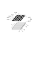
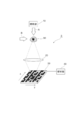
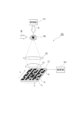
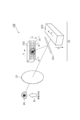
- FIG. 1 is a diagram illustrating a configuration of an imaging apparatus 1 according to the first embodiment.
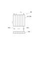
- FIG. 2 is a diagram illustrating the configuration of the detection unit 31 of the imaging device 1 according to the first embodiment.
- FIG. 3 is a diagram illustrating an image used in the simulation of the operation of the imaging device 1 according to the first embodiment.
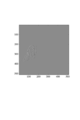
- FIG. 4 is a diagram illustrating a signal obtained by the detection unit 31 in the simulation of the operation of the imaging device 1 according to the first embodiment.
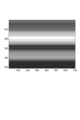
- FIG. 5 is a diagram illustrating the intensity distribution along the y direction of the image on the light receiving surface of the detection unit 31 of the imaging device 1 according to the first embodiment.
- FIG. 1 is a diagram illustrating a configuration of an imaging apparatus 1 according to the first embodiment.
- FIG. 2 is a diagram illustrating the configuration of the detection unit 31 of the imaging device 1 according to the first embodiment.
- FIG. 3 is a diagram illustrating an image used in the simulation of the operation of the imaging device 1 according to the first embodiment.
- FIG. 4 is
- FIG. 6 is a diagram illustrating an intensity distribution along the y direction of an image on the light receiving surface of the detection unit 31 of the imaging device 1 according to the first embodiment.
- FIG. 7 is a diagram illustrating an analysis process performed by the analysis unit 40 of the imaging device 1 according to the first embodiment.
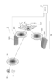
- FIG. 8 is a diagram illustrating the relationship between the visual field and the object group.
- FIG. 9 is a diagram illustrating an image obtained by the analysis unit 40 in the simulation of the operation of the imaging device 1 according to the first embodiment.
- FIG. 10 is a diagram illustrating an image used in another simulation of the operation of the imaging apparatus 1 according to the first embodiment.
- FIG. 11 is a diagram illustrating an image obtained by the analysis unit 40 in another simulation of the operation of the imaging device 1 according to the first embodiment.
- FIG. 12 is a diagram illustrating a configuration of the imaging apparatus 2 according to the second embodiment.
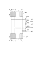
- FIG. 13 is a diagram illustrating a partial configuration of the detection unit 32 of the imaging device 2 according to the second embodiment.
- FIG. 14 is a diagram illustrating signals in the processes of the difference calculation unit 325 n and the analysis unit 42 of the imaging device 2 according to the second embodiment.
- FIG. 15 is a diagram illustrating a partial configuration of the detection unit 33 of the imaging device 3 according to the third embodiment.
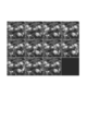
- FIG. 16 is a diagram illustrating an image used in the simulation of the operation of the imaging device 3 according to the third embodiment.
- FIG. 17 is a diagram illustrating a signal obtained by the detection unit 33 in the simulation of the operation of the imaging device 3 according to the third embodiment.
- FIG. 18 is a diagram illustrating an image obtained by the analysis unit in the simulation of the operation of the imaging device 3 according to the third embodiment.
- FIG. 19 is a diagram illustrating an image used in the simulation of the operation of the imaging apparatus according to the fourth embodiment.
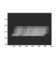
- FIG. 20 is a diagram illustrating a signal obtained by the detection unit when the butterfly object image is moving in the background in the simulation of the operation of the imaging apparatus according to the fourth embodiment.
- FIG. 21 is a diagram illustrating a signal obtained by the detection unit when there is no butterfly object image in the background in the simulation of the operation of the imaging apparatus according to the fourth embodiment.
- FIG. 22 is a diagram illustrating a signal obtained by subtracting the signal illustrated in FIG. 21 from the signal illustrated in FIG. 20 in the simulation of the operation of the imaging device according to the fourth embodiment.
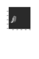
- FIG. 23 is a diagram illustrating an image obtained by the analysis unit based on the signal illustrated in FIG. 22 in the simulation of the operation of the imaging device according to the fourth embodiment.
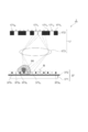
- FIG. 24 is a diagram illustrating a configuration of the imaging device 7 according to the seventh embodiment.
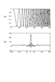
- FIG. 25 is a diagram illustrating the transmittance distribution based on the chirp signal in the mask of the imaging apparatus according to the eighth embodiment.
- FIG. 26 is a diagram illustrating signals obtained by the detection unit in the simulation of the operation of the imaging device according to the eighth embodiment.
- FIG. 27 is a diagram illustrating an image obtained by the analysis unit in the simulation of the operation of the imaging apparatus according to the eighth embodiment.
- FIG. 28 is a diagram illustrating a configuration of the imaging device 9 according to the ninth embodiment.
- FIG. 29 is a diagram illustrating the configuration of the detection unit 39 of the imaging device 9 according to the ninth embodiment.
- FIG. 30 is a diagram illustrating a two-dimensional pattern of the mask 392 used in the simulation of the operation of the imaging device 9 of the ninth embodiment.
- FIG. 31 is a diagram illustrating each signal in the simulation of the operation of the imaging device 9 according to the ninth embodiment.
- FIG. 32 is a diagram illustrating a configuration of an imaging apparatus 1A according to a modification of the first embodiment.
- FIG. 33 is a diagram illustrating a configuration of the imaging apparatus 100 according to the tenth embodiment.
- FIG. 34 is a diagram illustrating a partial configuration of the detection unit 50 of the imaging device 100 according to the tenth embodiment.
- FIG. 35 is a diagram illustrating an image used in the simulation of the operation of the imaging device 100 according to the tenth embodiment.
- FIG. 36 is a diagram illustrating a signal obtained by the detection unit 50 in the simulation of the operation of the imaging device 100 according to the tenth embodiment.
- FIG. 37 is a diagram illustrating an image obtained by the analysis unit in the simulation of the operation of the imaging device 100 according to the tenth embodiment.
- FIG. 1 is a diagram illustrating a configuration of an imaging apparatus 1 according to the first embodiment.
- the imaging device 1 includes an illumination unit 10 that irradiates a moving object 90 with light A, an optical system 20 that forms an image of the object 90, and an image of the object 90 that is formed by the optical system 20. And a detection unit 31 having a light-receiving surface, and an analysis unit 40 that analyzes a detection result of the detection unit 31 and obtains an image of the object 90.
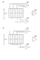
- FIG. 2 is a diagram illustrating the configuration of the detection unit 31 of the imaging device 1 according to the first embodiment.
- the illumination unit 10 outputs continuous light or pulsed light having a constant period, and irradiates the object 90 with the light A.
- the detector 31 includes a plurality of light receiving cells d 1 to d N arranged in the first direction (x direction) on the light receiving surface.
- the detector 31 is arranged so that the image moves in parallel with the second direction (y direction) on the light receiving surface as the object 90 moves in the direction B.
- the first direction (x direction) and the second direction (y direction) are orthogonal to each other.
- the detection unit 31 performs light reception or non-light reception according to the pseudo noise code sequence along the second direction (y direction) in each of the plurality of light receiving cells d 1 to d N , and the plurality of light receiving cells d 1 to d N and outputs an electric signal corresponding to the respective received light amounts.
- N is an integer of 2 or more.
- the detection unit 31 is configured by bonding a mask 312 on the light receiving surface of the one-dimensional line sensor 311.
- N light receiving cells d 1 to d N are arranged in the x direction.
- Each light-receiving cell d n is longer in the y direction. Or, it may include a case where it can be regarded as being long in the y direction by an optical image enlargement / reduction technique using a cylindrical lens or the like.
- N pseudo noise code sequence masks m 1 (y) to m n (y) are arranged in the x direction.
- the pseudo noise code sequence mask is a mask in which a pattern is engraved according to a certain pseudo noise code sequence.
- Each pixel of the pseudo-noise code sequence mask preferably has a square pixel in order to acquire an image.
- the scale in the optical y direction by the cylindrical lens 21 or the like is used. This includes the case where it can be regarded as a square pixel due to expansion.
- it can be regarded as a square pixel as a result of optical reduction of the image in the y direction. This effect can be expected to improve the image quality because the time during which the image is formed on the detection surface becomes longer.
- Each pseudo noise code sequence mask m n (y) is arranged on the corresponding light receiving cells d n, it performs one of transmission and blocking of light in accordance with the pseudo-noise code sequence along the y direction. In each of FIGS. 1 and 2, one of light transmission and blocking in the mask 312 is shown in black, and the other is shown in white. Any two pseudo-noise code sequences m n1 (y) and pseudo-noise code sequences m n2 (y) may be the same pseudo-noise code sequences or different pseudo-noise code sequences. . n, n1, and n2 are integers of 1 or more and N or less.
- the pseudo-noise code sequence includes a gold sequence, a preferred gold sequence, an orthogonal gold sequence, a gold-like sequence, a bulk sequence, a No sequence, a pseudo-ternary M sequence, a complementary sequence (see JP 2008-199140 A), and a Barker sequence.
- Golay series MJEGolay, "Complementary sequence,” IRE Transactions onInformation theory, pp.82-87, (1961)
- self-complementary sequences fully complementary sequences
- S.Naoki “Modulatable orthogonal sequences and their application to SSMA systems, "IEEE trans. on Information The theory, vol.IT-34, pp. 93-100, (1988)
- etc. can be used.
- Non-patent literature that summarizes the M-sequence (“sequences based on the M-sequence and its application to communication”, fundamentals Reviews, Vol. 3, No. 1, 32-42, 2009) Please refer to the following pseudo-noise code sequence.
- the M sequence that is one of the pseudo-noise code sequences is a binary (1/0 or -1 / + 1) periodic signal.
- the first M-sequence periodic signal is referred to as m1
- the second M-sequence periodic signal is referred to as m2.
- m 2 [0,0,0,0,0,1,1,1,1,0,1,1,1,1,1,0,0,0,1,0,. , 1,1,0,1,1,1,1,0,0,0,0,1,1,1,1,1,1,1,1] with 0 and 1 Is a code string.
- the pseudo noise code sequence mask m n (y) blocks light when the code is 0, and transmits light when the code is 1.
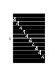
- FIG. 3 is a diagram illustrating an image used in the simulation of the operation of the imaging device 1 according to the first embodiment. It is assumed that the white character “4” is translated from left to right in the y direction in a uniform black background. The size of the character image on the light receiving surface of the detector 31 was 66 pixels in the x direction and 46 pixels in the y direction.
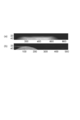
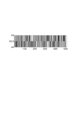
- FIG. 4 is a diagram illustrating a signal obtained by the detection unit 31 in the simulation of the operation of the imaging apparatus 1 according to the first embodiment.
- the horizontal axis represents time and the vertical axis represents the pixel position in the x direction.
- the right end is the output data of the detecting unit 31 at time 0 (the uppermost state in FIG. 3), and the left end is the output of the detecting unit 31 at the time 555 ⁇ t (the lowermost state in FIG. 3). It is data.
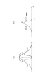
- FIGS. 5 and 6 are diagrams illustrating the intensity distribution along the y direction of the image on the light receiving surface of the detection unit 31 of the imaging device 1 of the first embodiment.
- 5 (a) shows the intensity along the y-direction of a certain image on the light receiving cell d n of the light-receiving surface distribution h a (y) by a solid line, an inverting the intensity distribution h (y) is the y-axis
- the distributed distribution h ( ⁇ y) is indicated by a broken line. In fact, it is not a calculation problem to handle an image formed on the light receiving surface on the assumption that the image is inverted with respect to the y-axis.
- FIG. 5B shows the distribution h (Vt ⁇ y) at time t when the distribution h ( ⁇ y) assumed to be inverted moves at the speed V in the + y direction.
- Equation (2) h (Vt ⁇ y) is replaced by h (y) and m (y) is replaced by m (Vt ⁇ y).
- Formula is derived. That is, as shown in FIG. 5, the image on the light receiving cell d n, instead of thinking as inverted distribution h (Vt-y) with respect to the y axis the intensity distribution h (y), the pseudo-noise code sequence m ( Consider a pseudo-noise code sequence m (Vt ⁇ y) that inverts y) with respect to the y-axis and moves at a speed V.
- Equation (3) represents the convolution integral of the pseudo noise code sequence m (y) and the intensity distribution h (y). That is, only pasting the pseudo noise code sequence mask m n (y) in the light receiving cell d n, a pseudo-noise code sequence m n (y) and the intensity distribution h (y) convolution integration result and thus, the light receiving cell d It is obtained as a time waveform of the signal output from n .
- FIG. 4 shows the result of such convolution integration.
- An M sequence is adopted as the pseudo noise code sequence and is called m (y).
- m ′ (y) is a sequence in which the element 0 of the pseudo noise code sequence m (y) is ⁇ 1 and the sequence in which the element 1 of the pseudo noise code sequence m (y) is 1, this m (y)
- a pair of m ′ (y) is called a quasi-orthogonal M sequence pair.
- the cross-correlation function r ( ⁇ ) between the above expression (3) and the pseudo noise code sequence m ′ (y) is expressed by the following expression (4).
- R mm ′ is represented by the following formula (5).
- equation (4) indicates that the correlation function of m ′ (y ′) and I dn (y ′) is a convolution integral of intensity distributions h (y) and R mm ′ (y).
- R mm ′ is a function corresponding to a Dirac delta function that is 0 other than 0 shift
- a waveform proportional to the intensity distribution h (y) can be obtained for r dn .
- the above equation (3) means cyclic convolution integration.
- the above equation (3) as a cyclic convolution integral is expressed as a matrix
- the following equation (6) is obtained.
- I dn (y ') are the result of the time-sampled obtained from the light receiving cell d n, since the discrete time-series data, it simply denoted as I i.
- the above expression (4) is similarly expressed as a matrix, the following expression (7) is obtained.
- E is a unit matrix of K rows and K columns.
- the periodic cross-correlation function r dn ( ⁇ ) between I dn (y ′) and the pseudo-noise code sequence m ′ (y) in the above equation (3) is an image h whose amplitude is amplified by (K + 1) / 2 times. (y) is represented.
- the still image of the object 90 is obtained after the luminance is amplified.
- a specific example of the quasi-orthogonal M series pair is as follows.
- the pair m ′ with respect to the M sequence m represented by the equation (8) is represented by the equation (9).
- the periodic autocorrelation function R mm of the pseudo noise code sequence m is expressed by equation (10).
- the periodic autocorrelation function R m′m ′ of the pseudo noise code sequence m ′ is expressed by the equation (11). In Expressions (10) and (11), it is not 0 other than 0 shift.
- the periodic cross-correlation function R mm ′ between the quasi-orthogonal M series pair m and m ′ is expressed by the following equation (12).
- the periodic cross-correlation function R mm ′ between the quasi-orthogonal M series pair m and m ′ is a correlation function that is all zero except for 0 shift.
- “0 shift” means that the delay amount ⁇ in equation (5) when obtaining the correlation function is zero.
- the analysis unit 40 demodulates the image of the object 90 based on the signal (FIG. 4) obtained by the detection unit 31 by using the above relationship. Since the output signal of the detection unit 31 is the result of linear convolution integration, it is necessary to correct this to the form of cyclic convolution integration.
- FIG. 7 is a diagram schematically showing how the linear convolution integration result of FIG. 4 is converted into a cyclic convolution integration form. With cumulative addition, the following equation (14) is executed.
- S (x1: x2, t1: t2) is an element surrounded by the x direction [x1 to x2] and the time t direction [t1 to t2] among the results shown in FIG. A symbol that is regarded as a matrix.
- the cyclic convolution integral shown in the equation (6) was corrected.
- FIG. 9 is a diagram illustrating an image obtained by the analysis unit 40 in the simulation of the operation of the imaging device 1 according to the first embodiment.
- a still image h (y) as shown in FIG. 9 is obtained by performing the calculation of the above expression (7) for each row (for each pixel) transformed into the cyclic convolution integral according to the expression (14).
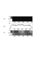
- FIG. 10 and 11 are diagrams illustrating another simulation example of the operation of the imaging apparatus 1 according to the first embodiment.
- FIG. 10 is a diagram illustrating an image used in another simulation.
- FIG. 11 is a diagram illustrating an image obtained by the analysis unit 40 in another simulation.
- a circular aperture having a diameter of 200 ⁇ m was moved at a speed of 14 ⁇ m / second and photographed with a 30 fps CCD camera using an objective lens with a magnification of 20 times.
- the CCD camera had 480 (x) ⁇ 640 (y) pixels, and one pixel size was 8.3 ⁇ 8.3 ⁇ m.
- the actually used pixels were 44 (x) ⁇ 511 (y).
- FIG. 10 shows a state in which a part of the circular opening moves at a constant speed from the left to the right in the field of view.
- FIG. 11A shows output data of a 44-pixel one-dimensional line sensor with the horizontal axis as time and the vertical axis as pixel number.
- FIG. 11B shows the result of demodulating a part of the circular aperture using the equation (7).
- the imaging apparatus 1 of the present embodiment can obtain a still image of a moving object using a one-dimensional line sensor.
- the imaging apparatus 1 of the present embodiment does not generate a pseudo noise code sequence as a time series signal, but has a pseudo noise code sequence mask fixed on the light receiving surface of the one-dimensional line sensor. Therefore, the imaging apparatus 1 of the present embodiment can obtain an image of the target object as a still image even when the target object is moving at high speed.
- FIG. 12 is a diagram illustrating a configuration of the imaging apparatus 2 according to the second embodiment.
- the imaging device 2 includes an illumination unit that irradiates light to a moving object 90, an optical system 20 that forms an image of the object 90, and an image of the object 90 formed by the optical system 20.
- FIG. 13 is a diagram illustrating a partial configuration of the detection unit 32 of the imaging device 2 according to the second embodiment. These drawings mainly show the configuration of the detection unit 32 of the imaging apparatus 2 of the second embodiment. Other components are the same as those in the first embodiment.
- the detection unit 32 includes a digital micromirror device (DMD) 320, an optical system 321, an optical system 322, a one-dimensional line sensor 323, a one-dimensional line sensor 324, and difference calculation units 325 1 to 325 N.
- the DMD 320 is configured by arranging a plurality of micromirrors each having a variable orientation of a reflecting surface in both the x direction and the y direction.
- the plurality of micromirrors are approximately 10 ⁇ m mirrors, and are disposed on the light receiving surface on which the image of the object 90 is formed by the optical system 20.
- the optical system 321 forms an image of light that has arrived from the DMD 320 on the light receiving surface of the one-dimensional line sensor 323.
- the optical system 322 forms an image of the light reaching from the DMD 320 on the light receiving surface of the one-dimensional line sensor 324.
- N light receiving cells d 1 to d N are arranged in the x direction.
- Each light-receiving cell d n is longer in the y direction. Or it can be regarded as optically long.
- DMD 320 N pseudo noise code sequences m 1 (y) to m n (y) are arranged in the x direction, and each value of the pseudo noise code sequence m n (y) is arranged in the y direction. micromirrors in the corresponding positions in accordance with the value of the noise code sequence m n (y) for reflecting the light to the one of the light receiving cells d n of the one-dimensional line sensor 323 and the one-dimensional line sensor 324.
- micromirrors value at position -1 to the light receiving cell d n of the one-dimensional line sensor 323 to reflect light micromirrors value is in the position +1 to reflect light to the light receiving cell d n of the one-dimensional line sensor 324.
- the pseudo noise code sequence m n1 (y) and the pseudo noise code sequence m n2 (y) may be the same or different pseudo noise code sequences.
- FIG. 14 is a diagram illustrating signals in the processes of the difference calculation unit 325 n and the analysis unit 42 of the imaging device 2 according to the second embodiment.
- Each difference calculation part 325 n has a data output from the light receiving cell d n of the one-dimensional line sensor 323 (FIG. (A)), data (FIG output from the light receiving cell d n of the one-dimensional line sensor 324 (B)) and a signal I dn (t) representing the difference between them is output ((c) in the figure).
- This signal I dn (t) corresponds to I dn (y ′) in the above equation (3).
- the DMD 320 uses an M sequence that takes a binary value of -1 / + 1 as the pseudo-noise code sequence m n (y), a pseudo-orthogonal M sequence pair that takes a binary value of 0 / + 1 when demodulating in the analysis unit 42. Can be used to obtain a cross-correlation function R mm ′ (Equation (12)) that is all zero except for 0 shift. Even if it is, the image of the object can be obtained as a still image ((d) in the figure).
- the first embodiment about half of the light reaching the detection unit 31 is received by the one-dimensional line sensor 311, whereas in the second embodiment, most of the light reaching the detection unit 32. All the light is received by the one-dimensional line sensor 323 or the one-dimensional line sensor 324. Therefore, in the second embodiment, it is possible to take an image with twice the amount of light as compared to the case of the first embodiment.
- FIG. 15 is a diagram illustrating a partial configuration of the detection unit 33 of the imaging device 3 according to the third embodiment.
- the imaging device 3 includes an illumination unit that irradiates light to a moving object, an optical system that forms an image of the object, and a light receiving surface on which the image of the object is formed by the optical system.
- a detection unit 33 having an analysis unit that analyzes a detection result of the detection unit 33 and obtains an image of the object.
- This figure mainly shows the configuration of the detection unit 33 of the imaging apparatus 3 of the third embodiment. Other components are the same as those in the first embodiment.
- the detection unit 33 includes a one-dimensional line sensor 331, a mask 332, capacitors 333 1 to 333 N, and a CCD shift register 334.
- Each of the one-dimensional line sensor 331 and the mask 332 is the same as that in the first embodiment.
- Each capacitor 333 n outputs the AC component of the output signal from the light receiving cell d n of the one-dimensional line sensor 331 to the CCD shift register 334.
- the CCD shift register 334 inputs the charge signals output from the capacitors 333 1 to 333 N in parallel, and outputs these charge signals serially to the analysis unit. Based on the electrical signal output from the CCD shift register 334, the analysis unit obtains an edge-enhanced image of the object image by the same processing as in the first embodiment.
- FIG. 16 is a diagram illustrating an image used in the simulation of the operation of the imaging device 3 according to the third embodiment. As shown in the figure, it is assumed that the butterfly object image is translated in the y direction from left to right in a uniform black background.
- FIG. 17 is a diagram illustrating a signal obtained by the detection unit 33 in the simulation of the operation of the imaging device 3 according to the third embodiment. In the figure, the horizontal axis represents time and the vertical axis represents the pixel position in the x direction.
- FIG. 18 is a diagram illustrating an image obtained by the analysis unit 33 in the simulation of the operation of the imaging device 3 according to the third embodiment.
- the signal corresponding to the time derivative of the electrical signal output from the detection unit is analyzed by the analysis unit, so that the edge of the image of the object moving at high speed is obtained.
- An emphasized image is obtained.
- the background erasure can be realized at the same time when the edge-enhanced image of the image of the object is obtained.
- the configuration of the imaging apparatus of the fourth embodiment is substantially the same as that shown in FIG.
- the imaging apparatus according to the fourth embodiment is characterized by the processing content of the analysis unit.
- the analysis unit in the fourth embodiment includes an electrical signal output from the detection unit when the object is moving in the background, and an electrical signal output from the detection unit when the object is not present in the background. To selectively obtain an image of an object in the background.
- FIG. 19 is a diagram illustrating an image used in the simulation of the operation of the imaging apparatus according to the fourth embodiment. As shown in the figure, it is assumed that the butterfly object image is translated from left to right in the y direction in the background on which flowers and the like are drawn.
- FIG. 20 is a diagram illustrating a signal obtained by the detection unit when the butterfly object image is moving in the background in the simulation of the operation of the imaging apparatus according to the fourth embodiment.
- FIG. 21 is a diagram illustrating a signal obtained by the detection unit when there is no butterfly object image in the background in the simulation of the operation of the imaging apparatus according to the fourth embodiment. The signal shown in FIG. 21 may be prepared in advance.
- FIG. 21 may be prepared in advance.
- FIG. 22 is a diagram illustrating a signal obtained by subtracting the signal illustrated in FIG. 21 from the signal illustrated in FIG. 20 in the simulation of the operation of the imaging device according to the fourth embodiment. 20 to 22, the horizontal axis represents time, and the vertical axis represents the pixel position in the x direction.
- FIG. 23 is a diagram illustrating an image obtained by the analysis unit based on the signal illustrated in FIG. 22 in the simulation of the operation of the imaging apparatus according to the fourth embodiment.
- the moving object 90 is modulated by the pseudo-noise code sequence, so that the background image is obtained by the demodulation processing in the analysis unit similar to the case of the first embodiment. Are removed to selectively obtain an image of the object.
- the configuration of the imaging apparatus of the fifth embodiment is substantially the same as that shown in FIG. However, the imaging apparatus of the fifth embodiment, whenever the pseudo-noise code sequence m n of each light receiving cell d n (y) is different from each other, one of the output values of the N light receiving cells d 1 ⁇ d N is changed It is characterized in that the analysis unit analyzes the electrical signal sampled in order to obtain an image of the object.
- 0 or 1 may be output continuously as a property of the pseudo-noise code sequence.
- the output difference between time t and time t + ⁇ t is 0 even though the object is moving.
- it is preferable to attach a mask having a different pseudo noise code sequence to each light receiving cell. Equation (18) selects an M sequence as a pseudo-noise code, sets m 1 [a 1 , a 2 ,..., A N ⁇ 1 , a N ] as a basic M sequence, and sets this m 1 element to the left.
- the element content only M-sequence obtained by cyclically shifting the m 2 the M-sequence elements of the m 2 was further cyclically shifted by one element to the left and m 3, in general, one element of the elements of the m n to the left
- the M sequence that is cyclically shifted by mn + 1 is defined as mn + 1 .
- This matrix is also called an M-sequence Hadamard matrix.
- the optical system that forms an image of the object on the light receiving surface of the detection unit is provided between the object and the light receiving surface of the detection unit.
- the object is moved on the light receiving surface of the detection unit without providing an imaging optical system between the object and the light receiving surface of the detection unit.
- each pixel of the pseudo-noise code sequence mask is set to the same size or smaller than the resolution required when photographing the object. Is preferred. This is suitable for observing a cell as an object on a substrate in a micro TAS (Total Analysis System), a lab-on-chip, or the like.
- FIG. 24 is a diagram illustrating a configuration of the imaging device 7 according to the seventh embodiment.
- the imaging device 7 analyzes the illumination unit 17 that irradiates light to the moving object 90, the detection unit 37 that moves the object 90 on the light receiving surface, and the detection result by the detection unit 37.
- An analysis unit that obtains an image of the object 90.
- the illumination unit 17 irradiates the object 90 with light with an illumination pattern corresponding to the pseudo-noise code sequence along the direction corresponding to the y direction.
- the illumination unit 17 includes point light sources 171 1 to 171 K , a mask 172, and an optical system 173.
- the mask 172 has a transmission and blocking pattern corresponding to the pseudo-noise code sequence of period K, and transmits the light of the point light source 171 k corresponding to the transmission part in the pattern to the optical system 173.
- the optical system 173 focuses the light output from the transmission part of the mask 172 on the light receiving surface of the detection part 37.
- an illumination pattern according to the pseudo-noise code sequence is formed on the light receiving surface of the detector 37 along the y direction of the light receiving cell. Even if the mask 172 is not used, lighting and non-lighting of the point light sources 171 1 to 171 K are set in accordance with a pattern corresponding to the pseudo-noise code sequence in the mask 172, so that pseudo-noise is generated on the light-receiving surface of the detection unit 37. Illumination patterns 373 1 to 373 N according to the code sequence can be realized.
- the object 90 moving on the light receiving surface of the detection unit 37 is labeled with a fluorescent dye that absorbs one or more photons and emits fluorescence.
- the object 90 is excited by being irradiated with light from the point light source 171 k and generates fluorescence.
- the detection unit 37 includes a one-dimensional line sensor 371 and an optical filter 372.
- the optical filter 372 transmits fluorescence generated by the object 90 to the one-dimensional line sensor 371 and blocks excitation light.
- the one-dimensional line sensor 371 receives the light transmitted through the optical filter 372 and outputs an electrical signal corresponding to the received light amount to the analysis unit.
- the one-dimensional line sensor 371 in the seventh embodiment is the same as the one-dimensional line sensor 311 in the first embodiment, and a plurality of light receiving cells are arranged in the vertical direction on the paper surface.
- the analysis unit in the seventh embodiment can obtain a still image of the moving object 90 by performing the same processing as the analysis unit in the first embodiment.
- the imaging device 7 of the seventh embodiment moves the object 90 on the light receiving surface of the detection unit 37 as in the case of the sixth embodiment, the object on the substrate in a micro TAS or a lab-on-chip. It is suitable when observing the cells.
- the point light sources 171 1 to 171 K may be spatial point light sources, or temporal point light sources (temporal focusing technology, Dan Oron, “Scanningless depth-resolved microscopy,” Opt. Exp. 13, 1468, (2005).) May be prepared.
- the configuration of the imaging apparatus of the eighth embodiment is substantially the same as that shown in FIG. However, the imaging apparatus of the eighth embodiment is characterized in that the mask used together with the one-dimensional line sensor in the detection unit has a transmittance distribution based on the chirp signal.
- FIG. 25 is a diagram for explaining the transmittance distribution based on the chirp signal in the mask of the imaging apparatus according to the eighth embodiment.
- the chirp signal for example, a waveform called Time ⁇ ⁇ Stretched Pulse (hereinafter referred to as “TSP”) whose phase changes in proportion to the square of the frequency is used (for example, the document “Shinji Aoshima,“ Signal compression method using a personal computer ”). ”Measurement of sound field in pipes”, Journal of the Acoustical Society of Japan, 40,146-151,1984 ”).
- TSP Time ⁇ ⁇ Stretched Pulse
- FIG. 4A shows the TSP waveform.
- the horizontal axis represents the spatial direction (Y direction), and the vertical axis represents the transmittance in the range from 0 to 1. That is, a mask that allows light to pass between 0% and 100% while the frequency gradually changes in the spatial direction is attached to each light receiving cell of the one-dimensional line sensor.
- FIG. 4B shows the autocorrelation function of TSP.
- the autocorrelation function of the TSP has a peak with a sharp correlation value when the delay amount ⁇ is zero.
- FIG. 26 is a diagram illustrating signals obtained by the detection unit in the simulation of the operation of the imaging device according to the eighth embodiment.
- the horizontal axis represents time and the vertical axis represents the pixel position in the x direction.
- FIG. 27 is a diagram illustrating an image obtained by the analysis unit in the simulation of the operation of the imaging apparatus according to the eighth embodiment. As shown in the figure, also in this embodiment, even when the object is moving at high speed, an image of the object can be obtained as a still image.
- FIG. 28 is a diagram illustrating a configuration of the imaging device 9 according to the ninth embodiment.
- the imaging apparatus 9 includes an illumination unit 10 that irradiates a moving object 90 with light A, an optical system 20 that forms an image of the object 90, and an image of the object 90 that is formed by the optical system 20. And a detection unit 39 having a light-receiving surface, and an analysis unit 49 that analyzes a detection result of the detection unit 39 and obtains an image of the object 90.
- FIG. 29 is a diagram illustrating the configuration of the detection unit 39 of the imaging device 9 according to the ninth embodiment.
- the illumination unit 10 and the optical system 20 in the ninth embodiment are the same as those in the first embodiment.
- the detector 39 includes a plurality of light receiving regions d 1 to d N arranged in the first direction (x direction) on the light receiving surface. These light receiving regions d 1 to d N are only divided for convenience, and constitute one light receiving cell as a whole, and output an electrical signal corresponding to the total amount of light received.
- the detector 39 is arranged so that the image moves in a direction parallel to the second direction (y direction) on the light receiving surface as the object 90 moves in the direction B.
- the first direction (x direction) and the second direction (y direction) are orthogonal to each other.
- the detection unit 39 performs either light reception or non-light reception according to the pseudo noise code sequence along the second direction (y direction) in each of the plurality of light receiving regions d 1 to d N.
- Any two pseudo-noise code sequences among the pseudo-noise code sequences in each of the plurality of light receiving regions d 1 to d N are substantially orthogonal to each other. Note that code sequences in which the cross-correlation functions of two pseudo-noise code sequences are 0 in other than 0 shift and 0 shift are referred to as substantially orthogonal to each other.
- the detector 39 outputs an electrical signal corresponding to the total amount of light received in the plurality of light receiving regions d 1 to d N.
- the detection unit 39 is configured by bonding a mask 392 on the light receiving surface of the sensor 391.
- N light receiving areas d 1 to d N are arranged in the x direction. Each light receiving regions d n is longer in the y direction. Or it can be regarded as long through an optical system.
- N pseudo-noise code sequence masks m 1 (y) to m n (y) are arranged in the x direction. Each pseudo noise code sequence mask m n (y) is arranged on the corresponding light receiving regions d n, it performs one of transmission and blocking of light in accordance with the pseudo-noise code sequence along the y direction.
- the analysis unit 49 analyzes the electrical signal output from the detection unit 39 and obtains an image of the object.
- the N pseudo-noise code sequences m 1 (y) to m n (y) and the processing contents of the analysis unit 49 will be further described.
- the most suitable code as a spreading code used in the CDMA technology in the communication field has a sharp peak in autocorrelation function when the phase difference is 0 (that is, the Kronecker delta function).
- the autocorrelation function is 0 when is not 0, and the cross-correlation function of any two sequences is 0 except for 0 shift and 0 shift. That is, the following equation (19) is established.
- the matrix E represents a unit matrix
- the matrix O represents a matrix in which all elements have a value of 0.
- ⁇ represents a constant.
- symbol M in the formula is (18) as indicated formula, is a pseudo noise code sequence and m i, a matrix with a sequence that is cyclically shifted by one the element successively in a row. Further, the matrix M 'i, to the pseudo noise code sequence m i, the pseudo-noise code sequence by the correlation function becomes zero at non-zero shift m' and i, the sequence cyclically shifted by one the element sequentially A matrix with rows.
- the output signal I from the sensor 391 can be expressed by the following equation (20).
- the transposed matrix of the matrix M ′ n is applied to the equation (20), and the following equation (21) Like this.
- the signal r dn is the image formed in a region d n of the light-receiving surface (h n).
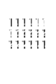
- FIG. 30 is a diagram illustrating a two-dimensional pattern of the mask 392 used in the simulation of the operation of the imaging device 9 of the ninth embodiment.
- the pattern is extended in the x direction for easy viewing.
- Each element of these M sequences m 1 and m 2 is a code of 0 or 1.
- the object 90 is assumed to move in the y direction.
- the mask pixel of 0 or 1 was 10 ⁇ 10 ⁇ m.
- FIG. 31 is a diagram illustrating each signal in the simulation of the operation of the imaging device 9 according to the ninth embodiment.
- FIG. 4A shows an image used in the simulation. It is assumed that a white-shaped object is translated in the y direction from left to right in a uniform black background.
- FIG. 5B shows a signal obtained by the detection unit 39 in the simulation. In the figure, the horizontal axis represents time, and the vertical axis represents the output signal I from the sensor 391 shown in equation (20).
- FIG. 6C shows an image obtained by the analysis unit 49 in the simulation.
- M i and M ′ i used at this time are quasi-orthogonal M-sequence pairs m i and m i ′ as in the case of the first embodiment, and their elements are cyclically shifted one by one as shown in equation (18). It is a matrix that has a series of rows in a row.
- the imaging device 9 of the present embodiment can obtain a still image of a moving object using a single pixel sensor.
- the imaging device 9 of the present embodiment does not generate a pseudo noise code sequence as a time series signal, but has a pseudo noise code sequence mask fixed on the light receiving surface of a single pixel sensor. Therefore, the imaging device 9 of the present embodiment can obtain an image of the target object as a still image even when the target object is moving at high speed.
- the autocorrelation function is divided into a periodic autocorrelation function and an aperiodic autocorrelation function.
- an M sequence and other code sequences having a property that the periodic autocorrelation function is all zero except for 0 shift are used.
- the tenth embodiment shows an example in which a self-complementary sequence that is a code sequence in which the aperiodic autocorrelation function is all 0 except for 0 shift is used.
- a series system represented by the following equations (22) and (23) is known as a self-complementary series.
- the non-periodic autocorrelation function of m 1 is expressed by the following formula (24)
- the non-periodic autocorrelation function of m 2 is expressed by the following formula (25).
- the respective aperiodic autocorrelation functions are added, the following equation (26) is obtained, and all the values other than 0 shift are 0.
- Equation (27) a matrix M 1 (Equation (27) below) having a row as a sequence obtained by sequentially acyclically shifting the elements of m 1 one by one. As shown in the equation (27), elements other than m 1 are filled with 0. Matrix product of the transposed matrix of this matrix M 1 is represented by the following equation (28).
- FIG. 33 is a diagram illustrating a configuration of the imaging apparatus 100 according to the tenth embodiment.
- the imaging apparatus 100 forms an illumination unit that irradiates light to a moving object 90, an optical system 20 that forms an image of the object 90, and an image of the object 90 formed by the optical system 20.
- a detection unit 50 having a light receiving surface, and an analysis unit that analyzes a detection result of the detection unit 50 and obtains an image of the object 90.
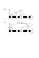
- FIG. 34 is a diagram illustrating a partial configuration of the detection unit 50 of the imaging device 100 according to the tenth embodiment. These drawings mainly show the configuration of the detection unit 50 of the imaging apparatus 100 according to the tenth embodiment.
- the detection unit 50 includes a half mirror 501, a two-dimensional sensor 502, a two-dimensional sensor 503, an adder 504 n , an adder 505 n , a subtractor 506 n , an adder 507 n , an adder 508 n and a subtractor 509 n .
- the optical system 20 images light from the object 90 on the light receiving surfaces of the two-dimensional sensor 502 and the two-dimensional sensor 503.
- the half mirror 501 splits the light from the optical system 20 into two, outputs one branched light to the two-dimensional sensor 502, and outputs the other branched light to the two-dimensional sensor 503.
- a fixed mask pattern according to the pseudo noise code sequence is not used. Instead, the pixels are electrically connected in the Y direction of the light receiving surface of the two-dimensional sensor 502 in accordance with the self-complementary series m 1 represented by the equation (22), and the linear relationship between the self-complementary series m 1 and the image is obtained.
- the convolution integral is expressed by the following equation (32). Further, the pixels are electrically connected in the Y direction of the light receiving surface of the two-dimensional sensor 503 according to the self-complementary series m 2 represented by the equation (23), and linear convolution integration between the self-complementary series m 2 and the image is performed. Is represented by the following equation (33).
- Two-dimensional sensor 502, 503 respectively of the pixel array d n (1), the output I dn of d n (2) (1), from I dn (2), in order to obtain an image without blur is (32) and What is necessary is just to add the transposed matrix of M 1 and M 2 from the left to the equation (33), and the following (34) is obtained.
- each element I k (1) of the vector on the middle side of the equation (32) is an output value of the two-dimensional sensor 502 at time k.
- each element I k (2) in the middle side of the expression (33) is an output value of the two-dimensional sensor 503 at time k.
- FIG. 34A shows a pixel array d n (1) arranged in the Y direction at a certain position X of the two-dimensional sensor 502.
- the pixel array d n (1) has a pixel structure in the Y direction, but the output of the pixel is connected to the adder 504 n or the adder 505 n according to the self-complementary series m 1 shown in the equation (22). ing. That is, each pixel corresponding to the element +1 of m 1 is connected to the adder 504 n, and the sum of these outputs is output from the adder 504 n .
- each pixel corresponding to element -1 of m 1 is connected to the adder 505 n, and the sum of these outputs is output from the adder 505 n . Then, an output difference between the adder 504 n and the adder 505 n is obtained by the subtractor 506 n . That is, the two-dimensional sensor 502 has a two-dimensional pixel structure on the light receiving surface, but outputs a signal having a value corresponding to the total intensity of light received by each pixel array d n (1) by subsequent electrical connection. .
- FIG. 34B shows a pixel array d n (2) arranged in the Y direction at a certain position X of the two-dimensional sensor 503.
- the pixel array d n (2) has a pixel structure in the Y direction, and the output of the pixel is connected to the adder 507 n or the adder 508 n according to the self-complementary series m 2 shown in the equation (23). ing. That is, each pixel corresponding to the element +1 of m 2 is connected to the adder 507 n, and the sum of these outputs is output from the adder 507 n .
- each pixel corresponding to element ⁇ 1 of m 2 is connected to the adder 508 n and the sum of these outputs is output from the adder 508 n . Then, an output difference between the adder 507 n and the adder 508 n is obtained by the subtracter 509 n . That is, in the two-dimensional sensor 503, the light receiving surface has a two-dimensional pixel structure, but outputs a signal having a value corresponding to the total intensity of light received by each pixel array d n (2) by electrical connection in the subsequent stage. .
- FIG. 35 is a diagram illustrating an image used in the simulation of the operation of the imaging device 100 according to the tenth embodiment. It is assumed that the white character “4” is translated from left to right in the y direction in a uniform black background in the order of the numbers shown in FIG. The size of the character image on the light receiving surface of the detection unit 50 was 66 pixels in the x direction and 8 pixels in the y direction. The field of view F and the moving object group G do not satisfy the relationship G ⁇ F.
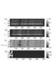
- FIG. 36 is a diagram illustrating a signal obtained by the detection unit 50 in the simulation of the operation of the imaging device 100 according to the tenth embodiment.
- FIG. 4A shows output data from one two-dimensional sensor 502, and
- FIG. 4B shows output data from the other two-dimensional sensor 503.
- FIG. FIG. 37 is a diagram illustrating an image obtained by the analysis unit in the simulation of the operation of the imaging device 100 according to the tenth embodiment.
- FIG. 4A shows the calculation result of M 1 T M 1 h
- FIG. 4B shows the calculation result of M 2 T M 2 h
- FIG. 4C shows the calculation result of the above equation (34). It is.
- an image of an object can be obtained as a still image even when the object is moving at high speed.
- the tenth embodiment since almost all of the light reaching the detection unit 50 is received by the two-dimensional sensor 502 or the two-dimensional sensor 503, the tenth embodiment has twice as much light as the first embodiment. Imaging can be performed.
- an optical system that forms an image of an object is provided, and the image of the object by the optical system is a light receiving surface of the detection unit. Is formed.
- the imaging apparatus according to each embodiment may include an optical component that emits an image of an object incident on one end surface from the other end surface.
- An optical component forms an image of an object on the light receiving surface of a detector by emitting an image of the object from the other end surface.
- an image fiber or an image fiber is formed into a taper shape. Fiber taper (Fiber Optic Tapers; FOT).
- the optical system may form an image of an object on one end surface of the optical component.
- the image fiber may be called by various names such as a fiber optic plate, an image conduit, or an image fiber bundle.
- the fiber taper can transmit an image incident on one end to the other end after being enlarged / reduced to a predetermined magnification. For example, an image of an object incident from an end face on the large diameter side of both end faces of the fiber taper is reduced and emitted on the end face on the small diameter side.
- the following effects can be obtained by using, for example, a fiber taper as an optical component.
- a fiber taper as an optical component.
- an image obtained directly from an object or an image of an object obtained through an optical system is incident on the end face on the large diameter side of the fiber taper, and an image emitted from the end face on the small diameter side is detected by light.
- a light detector having a small light receiving area can be used by guiding it to the light receiving surface of the detector. In general, the smaller the light receiving area, the better the frequency response of the photodetector. Therefore, by using a fiber taper, an object having a higher moving speed can be imaged.
- the present invention can be used as an imaging device that can obtain an image of an object as a still image even when the object is moving at high speed.
Landscapes
- Engineering & Computer Science (AREA)
- Multimedia (AREA)
- Signal Processing (AREA)
- Studio Devices (AREA)
- Length Measuring Devices By Optical Means (AREA)
Abstract
Priority Applications (3)
| Application Number | Priority Date | Filing Date | Title |
|---|---|---|---|
| US14/113,913 US9485393B2 (en) | 2011-04-25 | 2012-04-25 | Imaging device including detection unit having a light receiving plane |
| EP12777450.3A EP2704416B1 (fr) | 2011-04-25 | 2012-04-25 | Dispositif d'imagerie |
| JP2013512410A JP5886838B2 (ja) | 2011-04-25 | 2012-04-25 | 撮像装置 |
Applications Claiming Priority (2)
| Application Number | Priority Date | Filing Date | Title |
|---|---|---|---|
| JP2011-097341 | 2011-04-25 | ||
| JP2011097341 | 2011-04-25 |
Publications (1)
| Publication Number | Publication Date |
|---|---|
| WO2012147804A1 true WO2012147804A1 (fr) | 2012-11-01 |
Family
ID=47072321
Family Applications (1)
| Application Number | Title | Priority Date | Filing Date |
|---|---|---|---|
| PCT/JP2012/061112 Ceased WO2012147804A1 (fr) | 2011-04-25 | 2012-04-25 | Dispositif d'imagerie |
Country Status (4)
| Country | Link |
|---|---|
| US (1) | US9485393B2 (fr) |
| EP (1) | EP2704416B1 (fr) |
| JP (1) | JP5886838B2 (fr) |
| WO (1) | WO2012147804A1 (fr) |
Cited By (7)
| Publication number | Priority date | Publication date | Assignee | Title |
|---|---|---|---|---|
| JPWO2017073737A1 (ja) * | 2015-10-28 | 2018-09-27 | 国立大学法人 東京大学 | 分析装置 |
| US11579075B2 (en) | 2015-02-24 | 2023-02-14 | The University Of Tokyo | Dynamic high-speed high-sensitivity imaging device and imaging method |
| WO2023100734A1 (fr) * | 2021-11-30 | 2023-06-08 | コニカミノルタ株式会社 | Système de formation d'images, procédé de formation d'images et programme |
| US11788948B2 (en) | 2018-06-13 | 2023-10-17 | Thinkcyte, Inc. | Cytometry system and method for processing one or more target cells from a plurality of label-free cells |
| US12235202B2 (en) | 2019-12-27 | 2025-02-25 | Thinkcyte K.K. | Flow cytometer performance evaluation method and standard particle suspension |
| US12298221B2 (en) | 2020-04-01 | 2025-05-13 | Thinkcyte K.K. | Observation device |
| US12339217B2 (en) | 2020-04-01 | 2025-06-24 | Thinkcyte K.K. | Flow cytometer |
Families Citing this family (5)
| Publication number | Priority date | Publication date | Assignee | Title |
|---|---|---|---|---|
| JP5915949B2 (ja) * | 2014-06-25 | 2016-05-11 | パナソニックIpマネジメント株式会社 | 投影システム |
| US20160050376A1 (en) * | 2014-08-18 | 2016-02-18 | Ron Fridental | Image sensor with sub-wavelength resolution |
| US9706094B2 (en) * | 2014-12-05 | 2017-07-11 | National Security Technologies, Llc | Hyperchromatic lens for recording time-resolved phenomena |
| WO2019124106A1 (fr) * | 2017-12-22 | 2019-06-27 | ソニー株式会社 | Dispositif d'imagerie, procédé d'imagerie, et élément d'imagerie |
| US11244477B1 (en) | 2018-08-21 | 2022-02-08 | Perceive Corporation | Compressive sensing based image processing |
Citations (6)
| Publication number | Priority date | Publication date | Assignee | Title |
|---|---|---|---|---|
| JPH04336776A (ja) * | 1991-05-13 | 1992-11-24 | Olympus Optical Co Ltd | カメラシステム |
| JP2001197355A (ja) * | 2000-01-13 | 2001-07-19 | Minolta Co Ltd | デジタル撮像装置および画像復元方法 |
| JP2004506919A (ja) | 2000-08-25 | 2004-03-04 | アムニス コーポレイション | 細胞などの小さな移動物体の速度測定 |
| JP2005354157A (ja) * | 2004-06-08 | 2005-12-22 | Matsushita Electric Ind Co Ltd | 撮像装置 |
| JP2006050343A (ja) * | 2004-08-05 | 2006-02-16 | Univ Of Electro-Communications | 静止画像形成方法及びその記録装置 |
| JP2008199140A (ja) | 2007-02-09 | 2008-08-28 | Diaz Fuente Vincente | 相補系列によってsn比を改善する装置及び方法 |
Family Cites Families (4)
| Publication number | Priority date | Publication date | Assignee | Title |
|---|---|---|---|---|
| US6590979B1 (en) * | 1997-05-29 | 2003-07-08 | Macrovision Corporation | Method and apparatus for compression compatible video scrambling |
| US6849363B2 (en) * | 1997-06-27 | 2005-02-01 | Kabushiki Kaisha Toshiba | Method for repairing a photomask, method for inspecting a photomask, method for manufacturing a photomask, and method for manufacturing a semiconductor device |
| US7767949B2 (en) * | 2005-01-18 | 2010-08-03 | Rearden, Llc | Apparatus and method for capturing still images and video using coded aperture techniques |
| EP2296031A1 (fr) * | 2009-09-11 | 2011-03-16 | Astrium Limited | Détection d'un rayonnement électromagnétique |
-
2012
- 2012-04-25 JP JP2013512410A patent/JP5886838B2/ja active Active
- 2012-04-25 EP EP12777450.3A patent/EP2704416B1/fr active Active
- 2012-04-25 US US14/113,913 patent/US9485393B2/en active Active
- 2012-04-25 WO PCT/JP2012/061112 patent/WO2012147804A1/fr not_active Ceased
Patent Citations (7)
| Publication number | Priority date | Publication date | Assignee | Title |
|---|---|---|---|---|
| JPH04336776A (ja) * | 1991-05-13 | 1992-11-24 | Olympus Optical Co Ltd | カメラシステム |
| JP2001197355A (ja) * | 2000-01-13 | 2001-07-19 | Minolta Co Ltd | デジタル撮像装置および画像復元方法 |
| JP2004506919A (ja) | 2000-08-25 | 2004-03-04 | アムニス コーポレイション | 細胞などの小さな移動物体の速度測定 |
| JP2005354157A (ja) * | 2004-06-08 | 2005-12-22 | Matsushita Electric Ind Co Ltd | 撮像装置 |
| JP2006050343A (ja) * | 2004-08-05 | 2006-02-16 | Univ Of Electro-Communications | 静止画像形成方法及びその記録装置 |
| JP4452825B2 (ja) | 2004-08-05 | 2010-04-21 | 国立大学法人電気通信大学 | 静止画像形成方法及びその記録装置 |
| JP2008199140A (ja) | 2007-02-09 | 2008-08-28 | Diaz Fuente Vincente | 相補系列によってsn比を改善する装置及び方法 |
Non-Patent Citations (6)
| Title |
|---|
| "Pseudo-Noise Sequences Based on M-sequence and Its Application for Communications", FUNDAMENTALS REVIEWS, vol. 3, no. 1, 2009, pages 32 - 42 |
| "Scanningless depth-resolved microscopy", OPT. EXP., vol. 13, 2005, pages 1468 |
| AOSHIMA NOBUHARU: "Personal computer based signal compression method applied for a measurement of sound field in a pipe", ACOUSTICAL SCIENCE AND TECHNOLOGY, vol. 40, 1984, pages 146 - 151 |
| M. J. E. GOLAY: "Complementary sequence", IRE TRANSACTIONS ON INFORMATION THEORY, 1961, pages 82 - 87 |
| S. NAOKI: "Modulatable orthogonal sequences and their application to SSMA systems", IEEE TRANS. ON INFORMATION THE THEORY, vol. IT-34, 1988, pages 93 - 100, XP000560632, DOI: doi:10.1109/18.2605 |
| See also references of EP2704416A4 |
Cited By (13)
| Publication number | Priority date | Publication date | Assignee | Title |
|---|---|---|---|---|
| US11579075B2 (en) | 2015-02-24 | 2023-02-14 | The University Of Tokyo | Dynamic high-speed high-sensitivity imaging device and imaging method |
| US11867610B2 (en) | 2015-02-24 | 2024-01-09 | The University Of Tokyo | Dynamic high-speed high-sensitivity imaging device and imaging method |
| US11861889B2 (en) | 2015-10-28 | 2024-01-02 | The University Of Tokyo | Analysis device |
| US11542461B2 (en) | 2015-10-28 | 2023-01-03 | The University Of Tokyo | Analysis device |
| JPWO2017073737A1 (ja) * | 2015-10-28 | 2018-09-27 | 国立大学法人 東京大学 | 分析装置 |
| US11098275B2 (en) | 2015-10-28 | 2021-08-24 | The University Of Tokyo | Analysis device |
| US12230023B2 (en) | 2015-10-28 | 2025-02-18 | The University Of Tokyo | Analysis device |
| US11788948B2 (en) | 2018-06-13 | 2023-10-17 | Thinkcyte, Inc. | Cytometry system and method for processing one or more target cells from a plurality of label-free cells |
| US12259311B2 (en) | 2018-06-13 | 2025-03-25 | Thinkcyte K.K. | Methods and systems for cytometry |
| US12235202B2 (en) | 2019-12-27 | 2025-02-25 | Thinkcyte K.K. | Flow cytometer performance evaluation method and standard particle suspension |
| US12298221B2 (en) | 2020-04-01 | 2025-05-13 | Thinkcyte K.K. | Observation device |
| US12339217B2 (en) | 2020-04-01 | 2025-06-24 | Thinkcyte K.K. | Flow cytometer |
| WO2023100734A1 (fr) * | 2021-11-30 | 2023-06-08 | コニカミノルタ株式会社 | Système de formation d'images, procédé de formation d'images et programme |
Also Published As
| Publication number | Publication date |
|---|---|
| US9485393B2 (en) | 2016-11-01 |
| EP2704416A1 (fr) | 2014-03-05 |
| US20140078352A1 (en) | 2014-03-20 |
| JP5886838B2 (ja) | 2016-03-16 |
| EP2704416B1 (fr) | 2019-11-27 |
| JPWO2012147804A1 (ja) | 2014-07-28 |
| EP2704416A4 (fr) | 2014-09-17 |
Similar Documents
| Publication | Publication Date | Title |
|---|---|---|
| JP5886838B2 (ja) | 撮像装置 | |
| Liang | Punching holes in light: recent progress in single-shot coded-aperture optical imaging | |
| US11175489B2 (en) | Smart coded access optical sensor | |
| RU2653772C1 (ru) | Система формирования широкополосного гиперспектрального изображения на основе сжатого зондирования с нерегулярной дифракционной решеткой | |
| AU2016357089B2 (en) | Temporal compressive sensing systems | |
| KR101975081B1 (ko) | 펄스 조명을 사용한 동영상들의 고속 획득을 위한 방법 및 장치 | |
| CN104584533B (zh) | 图像取得装置以及摄像装置 | |
| Feng et al. | Digital micromirror device camera with per-pixel coded exposure for high dynamic range imaging | |
| JP7538624B2 (ja) | 時間分解ハイパースペクトル単一画素撮像 | |
| US8649002B2 (en) | Imaging system | |
| JP7050917B2 (ja) | 光を検出するための装置、システムおよび方法 | |
| JP5669071B2 (ja) | 時間相関カメラ | |
| Bouquet et al. | Design tool for TOF and SL based 3D cameras | |
| Abolbashari et al. | High dynamic range compressive imaging: a programmable imaging system | |
| Wang et al. | A fast auto-focusing technique for the long focal lens TDI CCD camera in remote sensing applications | |
| Kawachi et al. | Snapshot super-resolution indirect time-of-flight camera using a grating-based subpixel encoder and depth-regularizing compressive reconstruction | |
| Wang et al. | Clocking smear analysis and reduction for multi phase TDI CCD in remote sensing system | |
| CN109632729A (zh) | 基于波长分光法的超快连续成像方法 | |
| US11237047B2 (en) | Optical measurement device, optical measurement method, and scanning microscope | |
| WO2021131648A1 (fr) | Dispositif d'imagerie et procédé d'imagerie | |
| JP4401988B2 (ja) | 3次元画像情報取得装置 | |
| Ye et al. | Compressive confocal microscopy | |
| WO2021099761A1 (fr) | Appareil d'imagerie | |
| Mascarenas et al. | An event-driven light field, digital coded exposure imager architecture for per-pixel image regeneration in post processing | |
| Riza et al. | The CAOS camera–unleashing the power of full spectrum extreme linear dynamic ranging imaging |
Legal Events
| Date | Code | Title | Description |
|---|---|---|---|
| 121 | Ep: the epo has been informed by wipo that ep was designated in this application |
Ref document number: 12777450 Country of ref document: EP Kind code of ref document: A1 |
|
| ENP | Entry into the national phase |
Ref document number: 2013512410 Country of ref document: JP Kind code of ref document: A |
|
| NENP | Non-entry into the national phase |
Ref country code: DE |
|
| WWE | Wipo information: entry into national phase |
Ref document number: 2012777450 Country of ref document: EP |
|
| WWE | Wipo information: entry into national phase |
Ref document number: 14113913 Country of ref document: US |