WO2012148201A2 - Machine hydraulique entraînée par un moteur à combustion interne et surpresseur d'air pour ladite machine - Google Patents
Machine hydraulique entraînée par un moteur à combustion interne et surpresseur d'air pour ladite machine Download PDFInfo
- Publication number
- WO2012148201A2 WO2012148201A2 PCT/KR2012/003261 KR2012003261W WO2012148201A2 WO 2012148201 A2 WO2012148201 A2 WO 2012148201A2 KR 2012003261 W KR2012003261 W KR 2012003261W WO 2012148201 A2 WO2012148201 A2 WO 2012148201A2
- Authority
- WO
- WIPO (PCT)
- Prior art keywords
- hydraulic
- internal combustion
- combustion engine
- working fluid
- air
- Prior art date
- Legal status (The legal status is an assumption and is not a legal conclusion. Google has not performed a legal analysis and makes no representation as to the accuracy of the status listed.)
- Ceased
Links
Images
Classifications
-
- E—FIXED CONSTRUCTIONS
- E02—HYDRAULIC ENGINEERING; FOUNDATIONS; SOIL SHIFTING
- E02F—DREDGING; SOIL-SHIFTING
- E02F9/00—Component parts of dredgers or soil-shifting machines, not restricted to one of the kinds covered by groups E02F3/00 - E02F7/00
- E02F9/20—Drives; Control devices
- E02F9/2058—Electric or electro-mechanical or mechanical control devices of vehicle sub-units
- E02F9/2062—Control of propulsion units
- E02F9/2066—Control of propulsion units of the type combustion engines
-
- F—MECHANICAL ENGINEERING; LIGHTING; HEATING; WEAPONS; BLASTING
- F02—COMBUSTION ENGINES; HOT-GAS OR COMBUSTION-PRODUCT ENGINE PLANTS
- F02B—INTERNAL-COMBUSTION PISTON ENGINES; COMBUSTION ENGINES IN GENERAL
- F02B33/00—Engines characterised by provision of pumps for charging or scavenging
- F02B33/32—Engines with pumps other than of reciprocating-piston type
- F02B33/34—Engines with pumps other than of reciprocating-piston type with rotary pumps
-
- E—FIXED CONSTRUCTIONS
- E02—HYDRAULIC ENGINEERING; FOUNDATIONS; SOIL SHIFTING
- E02F—DREDGING; SOIL-SHIFTING
- E02F9/00—Component parts of dredgers or soil-shifting machines, not restricted to one of the kinds covered by groups E02F3/00 - E02F7/00
- E02F9/20—Drives; Control devices
- E02F9/22—Hydraulic or pneumatic drives
- E02F9/2217—Hydraulic or pneumatic drives with energy recovery arrangements, e.g. using accumulators, flywheels
-
- F—MECHANICAL ENGINEERING; LIGHTING; HEATING; WEAPONS; BLASTING
- F02—COMBUSTION ENGINES; HOT-GAS OR COMBUSTION-PRODUCT ENGINE PLANTS
- F02B—INTERNAL-COMBUSTION PISTON ENGINES; COMBUSTION ENGINES IN GENERAL
- F02B39/00—Component parts, details, or accessories relating to, driven charging or scavenging pumps, not provided for in groups F02B33/00 - F02B37/00
- F02B39/16—Other safety measures for, or other control of, pumps
-
- F—MECHANICAL ENGINEERING; LIGHTING; HEATING; WEAPONS; BLASTING
- F02—COMBUSTION ENGINES; HOT-GAS OR COMBUSTION-PRODUCT ENGINE PLANTS
- F02B—INTERNAL-COMBUSTION PISTON ENGINES; COMBUSTION ENGINES IN GENERAL
- F02B63/00—Adaptations of engines for driving pumps, hand-held tools or electric generators; Portable combinations of engines with engine-driven devices
-
- F—MECHANICAL ENGINEERING; LIGHTING; HEATING; WEAPONS; BLASTING
- F02—COMBUSTION ENGINES; HOT-GAS OR COMBUSTION-PRODUCT ENGINE PLANTS
- F02D—CONTROLLING COMBUSTION ENGINES
- F02D23/00—Controlling engines characterised by their being supercharged
-
- F—MECHANICAL ENGINEERING; LIGHTING; HEATING; WEAPONS; BLASTING
- F02—COMBUSTION ENGINES; HOT-GAS OR COMBUSTION-PRODUCT ENGINE PLANTS
- F02D—CONTROLLING COMBUSTION ENGINES
- F02D29/00—Controlling engines, such controlling being peculiar to the devices driven thereby, the devices being other than parts or accessories essential to engine operation, e.g. controlling of engines by signals external thereto
- F02D29/02—Controlling engines, such controlling being peculiar to the devices driven thereby, the devices being other than parts or accessories essential to engine operation, e.g. controlling of engines by signals external thereto peculiar to engines driving vehicles; peculiar to engines driving variable pitch propellers
-
- F—MECHANICAL ENGINEERING; LIGHTING; HEATING; WEAPONS; BLASTING
- F02—COMBUSTION ENGINES; HOT-GAS OR COMBUSTION-PRODUCT ENGINE PLANTS
- F02D—CONTROLLING COMBUSTION ENGINES
- F02D29/00—Controlling engines, such controlling being peculiar to the devices driven thereby, the devices being other than parts or accessories essential to engine operation, e.g. controlling of engines by signals external thereto
- F02D29/04—Controlling engines, such controlling being peculiar to the devices driven thereby, the devices being other than parts or accessories essential to engine operation, e.g. controlling of engines by signals external thereto peculiar to engines driving pumps
-
- Y—GENERAL TAGGING OF NEW TECHNOLOGICAL DEVELOPMENTS; GENERAL TAGGING OF CROSS-SECTIONAL TECHNOLOGIES SPANNING OVER SEVERAL SECTIONS OF THE IPC; TECHNICAL SUBJECTS COVERED BY FORMER USPC CROSS-REFERENCE ART COLLECTIONS [XRACs] AND DIGESTS
- Y02—TECHNOLOGIES OR APPLICATIONS FOR MITIGATION OR ADAPTATION AGAINST CLIMATE CHANGE
- Y02T—CLIMATE CHANGE MITIGATION TECHNOLOGIES RELATED TO TRANSPORTATION
- Y02T10/00—Road transport of goods or passengers
- Y02T10/10—Internal combustion engine [ICE] based vehicles
- Y02T10/12—Improving ICE efficiencies
Definitions
- the present invention relates to an internal combustion engine driven hydraulic machine and an air supercharger therefor.
- Hydraulic machines widely used in heavy equipment, heavy trucks, ships, etc. are mainly driven by internal combustion engines such as diesel engines and gasoline engines. These internal combustion engines also serve to generate power for driving the transportation equipment when the hydraulic machine is mounted on the transportation equipment.
- the internal combustion engine generates power by inhaling fuel and external air and burning it internally, and outputs power generally in proportion to the amount of inhaled air and fuel, that is, the volume or displacement of the combustion chamber.
- the suction of the outside air is made by the action of the negative pressure due to the piston movement, the intake air amount inevitably falls short of the actual cylinder volume. For example, in the case of a 5000cc cylinder, only around 4000cc of air is sucked in, so that the actual potential capacity of the internal combustion engine is not fully utilized.
- an internal combustion engine driven hydraulic machine having an internal combustion engine, a hydraulic unit for supplying a working fluid, and at least one hydraulic actuating unit operated by the working fluid from the hydraulic unit.
- An air supercharger comprising: a branching part for branching and drawing the working fluid from a working fluid pipe circulating the hydraulic unit and the hydraulic actuating part; A hydraulic motor supplied with a working fluid from the branch; An air compressor for compressing air by the hydraulic motor and supplying compressed air to the internal combustion engine; It is achieved by an air supercharger for an internal combustion engine driven hydraulic machine, characterized in that it comprises a flow control valve interposed between the branch and the hydraulic motor.
- the hydraulic motor and the hydraulic operation unit may be disposed in parallel on the working fluid pipe with the branch portion therebetween.
- the hydraulic motor and the hydraulic operation unit may be disposed in series on the working fluid pipe with the branch portion therebetween.
- the hydraulic unit and the hydraulic operation unit may further include a branch valve for branching out to the hydraulic operation unit and the branch by controlling the operating fluid from the hydraulic unit.
- the hydraulic unit may be driven by the internal combustion engine, and may further include an additional internal combustion engine for driving the hydraulic unit.
- combustion efficiency between the air compressor and the internal combustion engine further comprises an intercooler for cooling the compressed air.
- an internal combustion engine a hydraulic unit operated by the internal combustion engine, at least one hydraulic operation unit operated by a working fluid from the hydraulic unit, and the air supercharger described above.
- a hydraulic machine is provided.
- the air supercharger and the hydraulic machine according to the present invention having the above configuration, it is possible to maximize the compression efficiency by compressing the air for the air supercharger using a part or the remaining energy of the working fluid for driving the hydraulic operation unit, the internal combustion
- the compression of the boost air is controlled according to the speed of operation of the engine, thereby providing the effect of optimizing the charge efficiency.
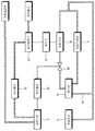
- FIG. 1 is a block diagram showing a hydraulic machine having an air supercharger according to a first embodiment of the present invention
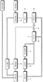
- FIG. 2 is a block diagram showing a hydraulic machine having an air supercharger according to a second embodiment of the present invention.
- the air supercharger according to the first embodiment of the present invention is constituted by an internal combustion engine 2, a hydraulic unit 4 for supplying a working fluid, and a working fluid from the hydraulic unit 4;
- a branch 10 is installed in a hydraulic machine having at least one hydraulic actuating part 6 in operation, branching out the working fluid from the working fluid pipe circulating the hydraulic unit 4 and the hydraulic actuating part 6.
- the hydraulic motor 30 receives the working fluid from the branch 10, the air compressor 50 for compressing the air by the hydraulic motor 30 to supply the compressed air to the internal combustion engine (2), And a controller 90 for controlling the flow regulating valve 80 according to the speed of the internal combustion engine 2, and a flow regulating valve 80 interposed between the branch 10 and the hydraulic motor 30.
- the hydraulic machine is an internal combustion engine 2 which is a driving source, a hydraulic unit 4 which is driven by the internal combustion engine 2 to supply a working fluid, and a hydraulic unit 4 It consists of a hydraulic actuating part 6 which is operated by the working fluid from
- the internal combustion engine 2 is usually a gasoline engine or a diesel engine, and receives fuel and air through a fuel supply unit and an intercooler, respectively, and burns the internal combustion engine to generate power. In some cases, there may be no intercooler, or may be supplied in the form of a mixture of fuel and air.
- an additional internal combustion engine for driving the hydraulic unit 4 may be further included, for example, when the internal combustion engine needs power for driving and power for generating a hydraulic actuating unit simultaneously. Can be applied.
- the hydraulic actuating unit 6 includes a hydraulic cylinder, a hydraulic motor, and the like for performing an inherent function of the hydraulic machine.
- the hydraulic actuating unit 6 performs an operation by the working fluid provided from the hydraulic unit 4 and supplies the working fluid to the hydraulic unit 4.
- a part of the working fluid from the hydraulic unit 4 is branched at the branch 10 and supplied to the hydraulic motor 30.
- the working fluid which is branched here is part of a very small amount of working fluid which performs a main function in the operation of the hydraulic actuating part 6, and is also a part of the spare working fluid which is usually prepared in the fluid machine.
- the working fluid drawn out from the branch 10 is provided to the hydraulic motor 30.
- the working fluid that has passed through the hydraulic motor 30 forms a parallel circulation circuit that joins with the working fluid exiting the hydraulic actuating part 6 and returns to the hydraulic unit 4.
- the working fluid branched from the branch 10 may further include a bypass pipe 62 for circulating the residual oil to the hydraulic unit (4) and
- the bypass tube 62 constitutes a circulation circuit between the hydraulic unit 4 and the branch 10.
- the hydraulic motor 30 rotates the impeller inside by the kinetic energy of the working fluid and generates a rotational driving force accordingly.
- the rotational driving force of the hydraulic motor 30 is transmitted to the air compressor 50 directly or indirectly. 1 is provided with a speed increaser 40 which increases the rotational output of the hydraulic motor 30 and transmits the same to the air compressor 50.
- the driving force of the hydraulic motor 30 transmitted through the speed increaser 40 compresses the air supplied to the air compressor 50 through the air filter.
- Compressed air leaving the air compressor 50 is supplied to the internal combustion engine 2 through cooling in the intercooler 70.
- the compressed air which is slightly elevated in the compression process, is sucked into the internal combustion engine at low pressure and high density by cooling in the intercooler 70 to improve combustion efficiency.
- Intercooler 70 is an optional component that can be selected whether or not installed depending on the operating environment of the hydraulic machine.
- a flow rate control valve 80 is provided between the branch portion 10 and the hydraulic motor 30 to adjust the amount of the working fluid flowing into the hydraulic motor 30. Since the hydraulic motor 30 generates an output depending on the flow rate of the working fluid, the flow rate and the degree of compression of the charge air can be controlled through the control of the flow control valve 80. Preferably, it is desirable to supply the boost air adaptively in proportion to the rotational speed of the internal combustion engine. So the controller 90 controls the flow rate control valve 80 by sensing the engine speed of the internal combustion engine. In some cases, however, it may not be necessary to control the engine speed to adapt in real time.
- the flow regulating valve 80 may be set to fit within the normal rotation speed range, and the opening degree of the valve may be set in several steps.
- Figure 2 shows a hydraulic machine having an air supercharger according to a second embodiment of the present invention. This embodiment is consistent with the above-described embodiment of FIG. 1 in the basic concept of generating the charge air with the drawn working fluid and supplying it to the internal combustion engine.
- the hydraulic motor 32 and the hydraulic actuating part 6 are arranged in series on the working fluid pipe with the branch part 12 interposed therebetween.
- (6) is arranged in parallel on the working fluid pipe with the branch portion 10 interposed therebetween.
- the hydraulic fluid from the hydraulic unit 4 is controlled between the hydraulic unit 4 and the hydraulic actuator 6 to branch to the hydraulic actuator 6 and the branch 12. It may further include a branch valve 20 for drawing out. Therefore, when the working fluid does not need to be provided to the hydraulic actuating part 6 or only partly, the branch valve 20 controls the oil supplied to the hydraulic actuating part 6 to control the oil through the bypass pipe 64. Can be diverted to the branch 12.
- bypass pipe for circulating residual oil to the hydraulic unit 4 when the working fluid passing through the branch valve 20 or the hydraulic actuating part 6 does not need to be provided to the hydraulic motor 32 or only partly.
- 66 may be further included, and the bypass pipe 62 constitutes a circulation circuit between the hydraulic unit 4 and the branch 12.
- the air supercharger of the present invention described above compresses the air for the air supercharger by using a part of the working fluid or the remaining energy for driving the hydraulic operation unit 6, thereby maximizing the compression efficiency, and the internal combustion engine 2 of the The compression rate of the boost air is controlled according to the operating speed, thereby optimizing the charging efficiency.
- the installation space is not limited. That is, a general air supercharger is connected to the crankshaft of the vehicle by a pulley and a belt, so that the installation position is limited to the upper or lower portion of the internal combustion engine, but the air supercharger according to the present invention is connected to the working fluid pipe so that the position can be freely set. Easy to install
Landscapes
- Engineering & Computer Science (AREA)
- General Engineering & Computer Science (AREA)
- Chemical & Material Sciences (AREA)
- Combustion & Propulsion (AREA)
- Mechanical Engineering (AREA)
- Mining & Mineral Resources (AREA)
- Civil Engineering (AREA)
- Structural Engineering (AREA)
- Supercharger (AREA)
Abstract
La présente invention concerne une machine hydraulique entraînée par un moteur à combustion interne et un surpresseur d'air pour ladite machine. Le surpresseur d'air selon un mode de réalisation de la présente invention est conçu pour la machine hydraulique entraînée par un moteur à combustion interne, comprenant : un moteur à combustion interne, une unité hydraulique destinée à apporter un fluide de travail et au moins un actionneur hydraulique actionné par le fluide de travail apporté par ladite unité hydraulique. Les caractéristiques techniques principales de la présente invention concernent un surpresseur d'air comprenant : une unité de séparation séparant et extrayant ledit fluide de travail d'un tuyau de fluide de travail contenant le fluide de travail circulant à travers ladite unité hydraulique et ledit actionneur hydraulique ; un moteur hydraulique auquel le fluide de travail est apporté par ladite unité de séparation ; un compresseur d'air destiné à comprimer l'air au moyen dudit moteur hydraulique et à apporter l'air comprimé au dit moteur à combustion interne ; et une soupape de réglage d'écoulement interposée entre ladite unité de séparation et ledit moteur hydraulique. Par conséquent, l'air pour le surpresseur d'air est comprimé au moyen d'une partie du fluide de travail pour faire fonctionner l'actionneur hydraulique ou au moyen de l'énergie restante, ce qui permet d'augmenter au maximum l'efficacité de la compression. De plus, le degré de compression de l'air surcomprimé est commandé en fonction de la vitesse de fonctionnement du moteur à combustion interne, et l'efficacité du chargement est ainsi optimisée.
Applications Claiming Priority (2)
| Application Number | Priority Date | Filing Date | Title |
|---|---|---|---|
| KR20110039222 | 2011-04-26 | ||
| KR10-2011-0039222 | 2011-04-26 |
Publications (2)
| Publication Number | Publication Date |
|---|---|
| WO2012148201A2 true WO2012148201A2 (fr) | 2012-11-01 |
| WO2012148201A3 WO2012148201A3 (fr) | 2013-03-21 |
Family
ID=47072927
Family Applications (1)
| Application Number | Title | Priority Date | Filing Date |
|---|---|---|---|
| PCT/KR2012/003261 Ceased WO2012148201A2 (fr) | 2011-04-26 | 2012-04-26 | Machine hydraulique entraînée par un moteur à combustion interne et surpresseur d'air pour ladite machine |
Country Status (2)
| Country | Link |
|---|---|
| KR (1) | KR101363014B1 (fr) |
| WO (1) | WO2012148201A2 (fr) |
Cited By (1)
| Publication number | Priority date | Publication date | Assignee | Title |
|---|---|---|---|---|
| CN111501886A (zh) * | 2020-05-12 | 2020-08-07 | 青田合页环保科技有限公司 | 一种河道自动清淤设备 |
Families Citing this family (1)
| Publication number | Priority date | Publication date | Assignee | Title |
|---|---|---|---|---|
| JP6409162B1 (ja) * | 2017-10-02 | 2018-10-24 | 株式会社三井E&Sマシナリー | 内燃機関の過給機余剰動力回収装置及び船舶 |
Family Cites Families (6)
| Publication number | Priority date | Publication date | Assignee | Title |
|---|---|---|---|---|
| JPH055228Y2 (fr) * | 1986-03-27 | 1993-02-10 | ||
| JPH051558A (ja) * | 1991-06-26 | 1993-01-08 | Hino Motors Ltd | エンジンへの過給および空気圧縮装置 |
| KR0151469B1 (ko) * | 1995-11-23 | 1998-10-01 | 정몽원 | 유압식 터보차져 시스템 |
| JP2008111384A (ja) * | 2006-10-31 | 2008-05-15 | Mitsui Eng & Shipbuild Co Ltd | 船舶用エンジンの余剰排気エネルギ回収システム |
| JP5037555B2 (ja) * | 2009-04-09 | 2012-09-26 | 住友重機械工業株式会社 | ハイブリッド型建設機械 |
| KR101312964B1 (ko) * | 2009-04-01 | 2013-10-01 | 스미도모쥬기가이고교 가부시키가이샤 | 하이브리드형 작업기계 |
-
2012
- 2012-04-26 WO PCT/KR2012/003261 patent/WO2012148201A2/fr not_active Ceased
- 2012-04-26 KR KR1020120043650A patent/KR101363014B1/ko not_active Expired - Fee Related
Cited By (2)
| Publication number | Priority date | Publication date | Assignee | Title |
|---|---|---|---|---|
| CN111501886A (zh) * | 2020-05-12 | 2020-08-07 | 青田合页环保科技有限公司 | 一种河道自动清淤设备 |
| CN111501886B (zh) * | 2020-05-12 | 2020-12-08 | 诸暨市智盈智能技术服务部 | 一种河道自动清淤设备 |
Also Published As
| Publication number | Publication date |
|---|---|
| WO2012148201A3 (fr) | 2013-03-21 |
| KR101363014B1 (ko) | 2014-02-24 |
| KR20120121370A (ko) | 2012-11-05 |
Similar Documents
| Publication | Publication Date | Title |
|---|---|---|
| KR101234633B1 (ko) | 터보 랙 개선 장치 | |
| CN102345535B (zh) | 用于内燃发动机的排气再循环系统 | |
| US10669955B2 (en) | Engine control device | |
| US20100139266A1 (en) | Systems for Recovering the Unused Energy of Exhaust Gas of an Internal Combustion Engine and Corresponding Methods | |
| KR101294050B1 (ko) | 터보 랙 개선 장치 | |
| JP6898346B2 (ja) | 高負荷対向ピストンエンジンの空気処理 | |
| JP5832616B2 (ja) | 二元燃料供給システムを有するターボ過給式大型低速2ストローク内燃機関 | |
| US20130233289A1 (en) | Supercharged Internal Combustion Engine | |
| CN104712419A (zh) | 发动机系统 | |
| JP6448361B2 (ja) | 内燃機関 | |
| CN104595011A (zh) | 发动机进气系统及汽车 | |
| WO2012148201A2 (fr) | Machine hydraulique entraînée par un moteur à combustion interne et surpresseur d'air pour ladite machine | |
| CN105705743B (zh) | 内燃机的增压器剩余动力回收装置 | |
| KR20170124622A (ko) | 내연 기관의 과급기 잉여 동력 회수 장치 | |
| CN104295377A (zh) | 发动机系统 | |
| KR20140142664A (ko) | 내연 기관의 작동 방법 | |
| CN104234856A (zh) | 用于控制机动车的制动力放大器内的真空压的方法 | |
| WO2013118308A1 (fr) | Dispositif de récupération d'énergie excédentaire de turbocompresseur pour moteur à combustion interne | |
| JP6558896B2 (ja) | 内燃機関 | |
| JP2011202591A (ja) | ブローバイガス還流装置 | |
| US10054039B2 (en) | Turbocharger system for an engine | |
| JP6537271B2 (ja) | 内燃機関 | |
| KR102012289B1 (ko) | 내연 기관의 과급기 잉여 동력 회수 장치 및 선박 | |
| JP6383925B1 (ja) | 内燃機関の過給機余剰動力回収装置及び船舶 | |
| CN116591928A (zh) | 用于压缩空气供应的方法和系统 |
Legal Events
| Date | Code | Title | Description |
|---|---|---|---|
| 121 | Ep: the epo has been informed by wipo that ep was designated in this application |
Ref document number: 12777111 Country of ref document: EP Kind code of ref document: A2 |
|
| NENP | Non-entry into the national phase |
Ref country code: DE |
|
| 122 | Ep: pct application non-entry in european phase |
Ref document number: 12777111 Country of ref document: EP Kind code of ref document: A2 |