WO2012153476A1 - Dispositif optique d'informations et procédé d'enregistrement ou de reproduction d'informations - Google Patents
Dispositif optique d'informations et procédé d'enregistrement ou de reproduction d'informations Download PDFInfo
- Publication number
- WO2012153476A1 WO2012153476A1 PCT/JP2012/002829 JP2012002829W WO2012153476A1 WO 2012153476 A1 WO2012153476 A1 WO 2012153476A1 JP 2012002829 W JP2012002829 W JP 2012002829W WO 2012153476 A1 WO2012153476 A1 WO 2012153476A1
- Authority
- WO
- WIPO (PCT)
- Prior art keywords
- recording
- layer
- light beam
- unit
- information
- Prior art date
- Legal status (The legal status is an assumption and is not a legal conclusion. Google has not performed a legal analysis and makes no representation as to the accuracy of the status listed.)
- Ceased
Links
Images





Classifications
-
- G—PHYSICS
- G11—INFORMATION STORAGE
- G11B—INFORMATION STORAGE BASED ON RELATIVE MOVEMENT BETWEEN RECORD CARRIER AND TRANSDUCER
- G11B21/00—Head arrangements not specific to the method of recording or reproducing
- G11B21/02—Driving or moving of heads
- G11B21/10—Track finding or aligning by moving the head ; Provisions for maintaining alignment of the head relative to the track during transducing operation, i.e. track following
- G11B21/106—Track finding or aligning by moving the head ; Provisions for maintaining alignment of the head relative to the track during transducing operation, i.e. track following on disks
-
- G—PHYSICS
- G11—INFORMATION STORAGE
- G11B—INFORMATION STORAGE BASED ON RELATIVE MOVEMENT BETWEEN RECORD CARRIER AND TRANSDUCER
- G11B7/00—Recording or reproducing by optical means, e.g. recording using a thermal beam of optical radiation by modifying optical properties or the physical structure, reproducing using an optical beam at lower power by sensing optical properties; Record carriers therefor
- G11B7/08—Disposition or mounting of heads or light sources relatively to record carriers
- G11B7/085—Disposition or mounting of heads or light sources relatively to record carriers with provision for moving the light beam into, or out of, its operative position or across tracks, otherwise than during the transducing operation, e.g. for adjustment or preliminary positioning or track change or selection
- G11B7/08505—Methods for track change, selection or preliminary positioning by moving the head
- G11B7/08511—Methods for track change, selection or preliminary positioning by moving the head with focus pull-in only
-
- G—PHYSICS
- G11—INFORMATION STORAGE
- G11B—INFORMATION STORAGE BASED ON RELATIVE MOVEMENT BETWEEN RECORD CARRIER AND TRANSDUCER
- G11B7/00—Recording or reproducing by optical means, e.g. recording using a thermal beam of optical radiation by modifying optical properties or the physical structure, reproducing using an optical beam at lower power by sensing optical properties; Record carriers therefor
- G11B2007/0003—Recording, reproducing or erasing systems characterised by the structure or type of the carrier
- G11B2007/0009—Recording, reproducing or erasing systems characterised by the structure or type of the carrier for carriers having data stored in three dimensions, e.g. volume storage
- G11B2007/0013—Recording, reproducing or erasing systems characterised by the structure or type of the carrier for carriers having data stored in three dimensions, e.g. volume storage for carriers having multiple discrete layers
-
- G—PHYSICS
- G11—INFORMATION STORAGE
- G11B—INFORMATION STORAGE BASED ON RELATIVE MOVEMENT BETWEEN RECORD CARRIER AND TRANSDUCER
- G11B7/00—Recording or reproducing by optical means, e.g. recording using a thermal beam of optical radiation by modifying optical properties or the physical structure, reproducing using an optical beam at lower power by sensing optical properties; Record carriers therefor
- G11B7/007—Arrangement of the information on the record carrier, e.g. form of tracks, actual track shape, e.g. wobbled, or cross-section, e.g. v-shaped; Sequential information structures, e.g. sectoring or header formats within a track
- G11B7/00736—Auxiliary data, e.g. lead-in, lead-out, Power Calibration Area [PCA], Burst Cutting Area [BCA], control information
-
- G—PHYSICS
- G11—INFORMATION STORAGE
- G11B—INFORMATION STORAGE BASED ON RELATIVE MOVEMENT BETWEEN RECORD CARRIER AND TRANSDUCER
- G11B7/00—Recording or reproducing by optical means, e.g. recording using a thermal beam of optical radiation by modifying optical properties or the physical structure, reproducing using an optical beam at lower power by sensing optical properties; Record carriers therefor
- G11B7/08—Disposition or mounting of heads or light sources relatively to record carriers
- G11B7/09—Disposition or mounting of heads or light sources relatively to record carriers with provision for moving the light beam or focus plane for the purpose of maintaining alignment of the light beam relative to the record carrier during transducing operation, e.g. to compensate for surface irregularities of the latter or for track following
- G11B7/095—Disposition or mounting of heads or light sources relatively to record carriers with provision for moving the light beam or focus plane for the purpose of maintaining alignment of the light beam relative to the record carrier during transducing operation, e.g. to compensate for surface irregularities of the latter or for track following specially adapted for discs, e.g. for compensation of eccentricity or wobble
- G11B7/0956—Disposition or mounting of heads or light sources relatively to record carriers with provision for moving the light beam or focus plane for the purpose of maintaining alignment of the light beam relative to the record carrier during transducing operation, e.g. to compensate for surface irregularities of the latter or for track following specially adapted for discs, e.g. for compensation of eccentricity or wobble to compensate for tilt, skew, warp or inclination of the disc, i.e. maintain the optical axis at right angles to the disc
Definitions
- a layer position detector for detecting which of the plurality of recording layers is the predetermined recording layer on which the focus of the reproducing light beam is located; and a layer detected by the layer position detector And a moving unit that moves the focus of the recording / reproducing light beam to a target position based on the position.
- layer position information for specifying the position of each recording layer is recorded in advance at a predetermined position of each recording layer before user data recording, and recording / reproduction is performed based on the recorded layer position information. It is detected which one of a plurality of recording layers is a predetermined recording layer on which the focal point of the optical beam for recording is located, and the focal point of the optical beam for recording / reproducing is based on the detected layer position Therefore, the focal point of the recording / reproducing light beam can be stably and rapidly moved from the current recording layer to the target recording layer.
- FIG. 1 is a block diagram showing the configuration of the optical disc apparatus according to Embodiment 1 of the present invention.
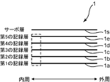
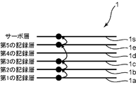
- FIG. 2 is a diagram illustrating an example of a servo layer and a plurality of recording layers of an optical disc on which an initial recording operation is performed.
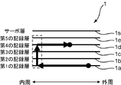
- FIG. 3 is a diagram showing an example of the movement pattern of the focus of the recording / reproducing light beam at the time of search.
- FIG. 4A is a diagram showing an example of the positional relationship between the focus of the servo light beam and the focus of the recording / reproducing light beam when the optical disc has no relative inclination.
- FIG. 4B is a diagram illustrating an example of the positional relationship between the focus of the servo light beam and the focus of the recording / reproducing light beam when the optical disc has a relative inclination.
- the optical disc 1 has a plurality of recording layers on which information is recorded and at least one servo layer used for servo control. As shown in FIG. 2, for example, the optical disc 1 includes first to fifth recording layers 1a to 1e and a servo layer 1s. In FIG. 2, the optical disc 1 has five recording layers. However, the present invention is not particularly limited to this, and there are two recording layers, three recording layers, four recording layers, or six or more recording layers. It may have a recording layer, and may have a plurality of recording layers. In FIG. 2, the optical disc 1 has one servo layer. However, the present invention is not particularly limited to this, and may have two or more servo layers, and at least one servo layer. As long as it has.
- the optical head 10 is a recording / reproducing light source that emits a recording / reproducing light beam, a servo light source that emits a servo light beam, and a recording / reproducing light beam emitted by the recording / reproducing light source.
- the search unit 22 moves the focus of the recording / reproducing light beam to a target position based on the layer position detected by the layer position detection unit 21. Based on the layer position information from the layer position detection unit 21, the search unit 22 sends a drive signal for searching (seeking) the focus of the recording / reproducing light beam to the target recording layer to the optical head 10.
- the optical head 10 moves the focal position of the recording / reproducing light beam based on the drive signal from the search unit 22.
- the radial position error detection unit 30 detects a radial position error of the recording / reproducing light beam.
- the initial recording unit 20 determines the width in the tracking direction of the recording area for pre-recording layer position information at a predetermined position of each recording layer based on the error detected by the radial position error detection unit 30.
- the initial recording unit 20 includes the layer position information in the data to be recorded, and performs the initial recording operation of the data including the layer position information.
- the recorded data is stored on the optical disc 1. Therefore, it is not necessary to perform the initial recording operation a plurality of times for one optical disc 1.
- the optical disc device 100 When the optical disc device 100 is activated, the optical disc device 100 reads the control data recorded on the optical disc 1 and confirms whether or not the initial recording operation has been performed. Thereafter, only when the initial recording operation is not performed, the initial recording unit 20 performs the initial recording operation and writes in the control data of the optical disc 1 that the initial recording operation has been performed. Thereby, the initial recording operation can be performed only once on one optical disc 1.
- the search unit 22 moves the focus of the recording / reproducing light beam in the focus direction from the first recording layer 1a to the fourth recording layer 1d.
- the focal point of the recording / reproducing light beam moves to the radial position where the initial recording operation is performed. Therefore, the layer position detector 21 can always acquire the current layer position information, and can stably and rapidly reach the focus of the recording / reproducing light beam.
- the initial recording unit 20 records the layer position information for all the recording layers at once.
- the present invention is not particularly limited to this.
- the initial recording unit 20 may perform the initial recording operation only on the recording layer on which recording is performed for the first time. That is, the initial recording unit 20 may record layer position information in advance at a predetermined position of one recording layer when user data is recorded for the first time on one of the plurality of recording layers of the optical disc 1. .
- the optical axis of the recording / reproducing light beam is perpendicular to the surface of the optical disk.
- the optical axis of the recording / reproducing light beam is not perpendicular to the surface of the optical disk. Note that the optical axis of the recording / reproducing light beam coincides with the optical axis of the servo light beam.
- the initial recording unit 20 records in advance information including layer position information at the recording start position of each recording layer using a recording / reproducing light beam before user data is recorded.
- the position where the layer position information is recorded is not limited to the recording start position.
- the initial recording unit 20 may record in advance information including layer position information at a predetermined position of each recording layer using a recording / reproducing light beam before the user data is recorded.
- the position where the layer position information is recorded may be the inner peripheral area of the optical disc 1, the outer peripheral area of the optical disc 1, or a predetermined position in the user data recording area of the optical disc 1.
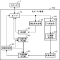
- FIG. 6 is a block diagram showing a configuration of an optical disc apparatus for recording layer position information in Embodiment 2 of the present invention.
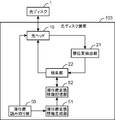
- FIG. 7 is a block diagram showing a configuration of an optical disc apparatus for moving a recording / reproducing light beam in the second embodiment of the present invention.
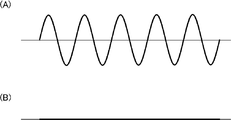
- FIG. 8A is a diagram illustrating an example of a signal output from the TE detection unit 42 when the recording / reproducing light beam is focused on the servo layer.
- the servo layer determination unit 44 includes a TE detection unit 42 and a TE amplitude measurement unit 43.
- the initial recording determination unit 40 receives a signal indicating that the initial recording operation is not being performed from the initial recording unit 20, or indicates that the initial recording operation is being performed from the initial recording unit 20. While the signal is being received, if the determination result from the end layer detection unit 41 indicates that the focal point of the recording / reproducing light beam is present in the recording layer, it is determined that the initial recording operation is not abnormal and the determination is made. The result is sent to the initial recording unit 20.
- the layer position reading unit 50 reads the layer position information recorded on each recording layer by the initial recording unit 20.
- the layer position conversion information generation unit 51 generates layer position conversion information in which the layer position information read by the layer position reading unit 50 is associated with the actual recording layer position.
- the layer position conversion information storage unit 52 stores the layer position conversion information generated by the layer position conversion information generation unit 51.
- the search unit 22 uses the layer position conversion information generated by the layer position conversion information generation unit 51 to convert the layer position information detected by the layer position detection unit 21 into the actual recording layer position for recording and reproduction. The focus of the light beam is moved to the target recording layer.
- the layer position reading unit 50 reads the layer position information recorded in each recording layer in the initial recording operation after the initial recording operation has been completed normally, and sends the read layer position information to the layer position conversion information generation unit 51.
- the layer position conversion information generation unit 51 generates a table (layer position conversion information) indicating the relationship between the layer position information from the layer position reading unit 50 and the actual recording layer position, and uses the generated table as the layer position conversion information.
- the search unit 22 uses the table stored in the layer position conversion information storage unit 52 to convert the recording layer position specified by the layer position information from the layer position detection unit 21 into the actual recording layer position. Then, a drive signal for moving the recording / reproducing light beam to the target recording layer is generated and sent to the optical head 10.
- a track exists in the servo layer 1 s of the optical disc 1.
- the TE detector 42 generates a TE signal in accordance with a change in the light amount signal from the optical head 10 generated by the track groove.
- the recording / reproducing light beam can be moved.
- the servo layer is arranged on the uppermost layer of the optical disc 1, but the present invention is not particularly limited to this, and the servo layer may be arranged on the lowermost layer or in the middle.
- FIG. 10 includes an optical head 10, an initial recording unit 20, a layer position detection unit 21, a search unit 22, an initial recording determination unit 40, an end layer detection unit 41, and an FE detection unit 46.
- the same components as those of the second embodiment shown in FIG. 10 are identical components as those of the second embodiment shown in FIG.
- the FE detection unit 46 detects a position shift signal corresponding to the position shift of the focal point of the recording / reproducing light beam with respect to the plurality of recording layers or at least one servo layer of the optical disc 1.
- the first recording unit 20 mistakenly moves the focus of the recording / reproducing light beam from the third recording layer 1c to the second recording layer 1b, for example, from the third recording layer 1c to the first recording layer.
- the initial recording unit 20 records layer position information indicating the second recording layer 1b with respect to the first recording layer 1a.
- the initial recording unit 20 moves the focus of the recording / reproducing light beam toward the surface of the optical disc 1 so as to move the focus of the recording / reproducing light beam to the first recording layer 1a.
- the layer position information is recorded on the first recording layer 1a without being recorded on the third recording layer 1c, and the focal point of the recording / reproducing light beam is the first recording layer.
- Over layer 1a If the number of recording layers in which the layer position information is recorded before exceeding the first recording layer 1a is 4, it can be determined that there is a recording layer in which the layer position information is not recorded. If the initial recording unit 20 searches for whether or not layer position information is recorded in order from the fifth recording layer 1e to the first recording layer 1a, the second recording layer 1b is not recorded. I understand that. Therefore, the initial recording unit 20 records the layer position information on the second recording layer 1b again.
- the recorded layer position is obtained when searching for the recording / reproducing light beam.
- the information shift is corrected, but the present invention is not particularly limited to this.
- the positional information may be recorded again to eliminate the deviation of the layer position information.
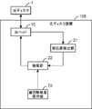
- FIG. 12 is a block diagram showing the configuration of the optical disc apparatus according to Embodiment 3 of the present invention.
- FIG. 13 is a diagram illustrating an example of a recording state of each recording layer of the optical disc 1.
- the optical disk device 106 corresponds to an example of an optical information device
- the optical head 10 corresponds to an example of a condensing irradiation unit
- the layer position detection unit 21 corresponds to an example of a layer position detection unit
- the search unit 22 corresponds to an example of a moving unit
- the interlayer driving amount holding unit 70 corresponds to an example of an interlayer driving amount holding unit.
- the interlayer driving amount holding unit 70 holds the driving amounts of the objective lens actuator and the collimating lens actuator included in the optical head 10.
- the objective lens actuator moves the objective lens in the optical axis direction and moves the focal point of the recording / reproducing light beam to the target recording layer.
- the collimating lens actuator moves the second collimating lens in the optical axis direction, and moves the focal point of the servo light beam to the servo layer.
- the search unit 22 detects that position control (focus control) in the direction perpendicular to the recording surface of the optical disc 1 at the focus of the servo light beam and the focus of the recording / reproducing light beam is not performed. In this case, the search unit 22 draws the focal point of the servo light beam into the servo layer and moves the focal point of the recording / reproducing light beam to a predetermined reference position.
- the interlayer driving amount holding unit 70 holds the driving amount of the optical head 10 for moving the focus of the recording / reproducing light beam from the reference position according to the distance between the servo layer and each recording layer. That is, the interlayer driving amount holding unit 70 holds the driving amount of the optical head 10 corresponding to the distance between the reference position and each recording layer in association with each recording layer.
- the search unit 22 uses the pre-designed drive amount held in the interlayer drive amount holding unit 70 to determine the focus of the recording / reproducing light beam and the focus of the servo light beam.
- the driving amount when the recording / reproducing light beam is actually condensed on each recording layer is measured, and the measured driving amount is held in the interlayer driving amount holding unit 70.
- the interlayer driving amount holding unit 70 determines whether the focal point of the servo light beam and the focal point of each recording layer of the recording / reproducing light beam when the focal point of the recording / reproducing light beam is focused on each recording layer. A driving amount for controlling the distance between them may be measured, and the measured driving amount may be held.
- a layer position detector for detecting which of the plurality of recording layers is the predetermined recording layer on which the focus of the reproducing light beam is located; and a layer detected by the layer position detector And a moving unit that moves the focus of the recording / reproducing light beam to a target position based on the position.
- an error in the radial position of the recording / reproducing light beam is detected, and based on the detected error, recording area tracking for pre-recording layer position information at a predetermined position of each recording layer is performed. The width of the direction is determined.
- the layer position information can be detected reliably.
- the optical information apparatus may further include a mechanical error amount holding unit that holds a mechanical error amount in the radial direction that occurs when the focal point of the recording / reproducing light beam is moved in the radial direction. It is preferable that the position error detection unit detects an error in a radial position of the recording / reproducing light beam based on the error amount held in the mechanical error amount holding unit.
- the mechanical error amount holding unit holds the radial mechanical error amount generated when the focal point of the recording / reproducing light beam is moved in the radial direction. Based on the error amount held in the mechanical error amount holding unit, an error in the position in the radial direction of the recording / reproducing light beam is detected.
- the layer position information can be reliably detected.
- the radial position error detection unit detects an error in a radial position of the recording / reproducing light beam, which is common to all recording layers.
- the radial position error detector detects an error in a radial position of the recording / reproducing light beam for each recording layer.
- the optical information apparatus may further include an end layer detection unit that detects that the focal point of the recording / reproducing light beam has passed the uppermost recording layer or the lowermost recording layer of the plurality of recording layers.
- the position information recording determination unit performs the end information detection unit before the target recording layer is reached.
- the focal point of the recording / reproducing light beam has passed the uppermost recording layer or the lowermost recording layer of the plurality of recording layers.
- the recording / reproducing light beam is focused on the upper recording layer or the lower recording layer before reaching the target recording layer.
- the layer position reading unit that reads the layer position information recorded on each recording layer by the layer position information recording unit, and the layer position information that is read by the layer position reading unit
- a layer position conversion information generating unit that generates layer position conversion information in association with the actual recording layer position
- the moving unit generates the layer position conversion information generated by the layer position conversion information generating unit. It is preferable that the layer position information detected by the layer position detector is converted into an actual recording layer position and the focus of the recording / reproducing light beam is moved to the target recording layer.
- the layer position information recording unit preferably records the layer position information in advance at a plurality of radial positions of each recording layer.
- the focus of the recording / reproducing light beam can be reliably moved.
- the end position holding unit holds the end position information for each recording layer
- the recording state information generation unit stores the end position information of each recording layer held in the end position holding unit. It is preferable to determine the recording state of each recording layer based on the end position information.
- the position control in the focus direction can be easily performed again.
- layer position information is recorded in advance at a predetermined position on each recording layer, so that, except when user data is recorded on the information carrier for the first time, Since the layer position information is not recorded, the startup time of the optical information device can be shortened.
- each recording layer is recorded at a predetermined position on each recording layer using the recording / reproducing light beam focused and irradiated on the plurality of recording layers before user data recording.
- Layer position information for specifying the position of the layer is recorded in advance.
- the layer position detecting step the layer position information recorded in the layer position information recording step in the predetermined recording layer is read using the recording / reproducing light beam, and the recording / reproducing light is based on the read layer position information. It is detected which of the plurality of recording layers is the predetermined recording layer where the focal point of the beam is located.
- the focus of the recording / reproducing light beam is moved to the target position based on the layer position detected in the layer position detecting step.
- layer position information for specifying the position of each recording layer is recorded in advance at a predetermined position of each recording layer before user data recording, and based on the recorded layer position information, the recording / reproducing light beam is recorded. It is detected which of the plurality of recording layers is the predetermined recording layer where the focal point is located, and based on the detected layer position, the focal point of the recording / reproducing light beam is moved to the target position. Therefore, the focal point of the recording / reproducing light beam can be stably and rapidly moved from the current recording layer to the target recording layer.
Landscapes
- Optical Recording Or Reproduction (AREA)
- Moving Of The Head For Recording And Reproducing By Optical Means (AREA)
Abstract
Priority Applications (3)
| Application Number | Priority Date | Filing Date | Title |
|---|---|---|---|
| JP2012552176A JPWO2012153476A1 (ja) | 2011-05-10 | 2012-04-25 | 光情報装置、及び情報記録又は再生方法 |
| US13/807,561 US20130100787A1 (en) | 2011-05-10 | 2012-04-25 | Optical information apparatus and information recording or reproducing method |
| CN201280001821.6A CN102971790A (zh) | 2011-05-10 | 2012-04-25 | 光信息装置及信息记录或再生的方法 |
Applications Claiming Priority (2)
| Application Number | Priority Date | Filing Date | Title |
|---|---|---|---|
| JP2011-104983 | 2011-05-10 | ||
| JP2011104983 | 2011-05-10 |
Publications (1)
| Publication Number | Publication Date |
|---|---|
| WO2012153476A1 true WO2012153476A1 (fr) | 2012-11-15 |
Family
ID=47138968
Family Applications (1)
| Application Number | Title | Priority Date | Filing Date |
|---|---|---|---|
| PCT/JP2012/002829 Ceased WO2012153476A1 (fr) | 2011-05-10 | 2012-04-25 | Dispositif optique d'informations et procédé d'enregistrement ou de reproduction d'informations |
Country Status (4)
| Country | Link |
|---|---|
| US (1) | US20130100787A1 (fr) |
| JP (1) | JPWO2012153476A1 (fr) |
| CN (1) | CN102971790A (fr) |
| WO (1) | WO2012153476A1 (fr) |
Families Citing this family (2)
| Publication number | Priority date | Publication date | Assignee | Title |
|---|---|---|---|---|
| USRE49652E1 (en) * | 2013-12-16 | 2023-09-12 | Qualcomm Incorporated | Power saving techniques in computing devices |
| CN106773651B (zh) * | 2016-12-31 | 2020-01-17 | 深圳市优必选科技有限公司 | 舵机临界点锁位方法和装置 |
Citations (5)
| Publication number | Priority date | Publication date | Assignee | Title |
|---|---|---|---|---|
| JPH03219440A (ja) * | 1989-10-30 | 1991-09-26 | Matsushita Electric Ind Co Ltd | 多層記録光ディスク |
| JPH09509776A (ja) * | 1994-12-19 | 1997-09-30 | フィリップス エレクトロニクス ネムローゼ フェンノートシャップ | 多層記録媒体及びこの記録媒体を走査する装置 |
| US20040001400A1 (en) * | 1999-07-29 | 2004-01-01 | Siros Technologies, Inc., A California Corporation | Optical data storage system with focus and tracking error correction |
| JP2010176762A (ja) * | 2009-01-30 | 2010-08-12 | Tdk Corp | 光記録再生方法 |
| WO2010150380A1 (fr) * | 2009-06-25 | 2010-12-29 | パイオニア株式会社 | Support d'enregistrement optique du type à séparation de couches de guidage, dispositif de commande de support d'enregistrement optique et procédé d'accès à la couche d'enregistrement |
Family Cites Families (6)
| Publication number | Priority date | Publication date | Assignee | Title |
|---|---|---|---|---|
| US6002655A (en) * | 1996-07-10 | 1999-12-14 | Hitachi, Ltd. | Optical disc apparatus accessing method and system therefor |
| US20020191501A1 (en) * | 2001-05-14 | 2002-12-19 | Matsushita Electric Industrial Co., Ltd. | Optical recording medium, optical pickup apparatus, and recording and reproducing apparatus |
| US20120069723A1 (en) * | 2009-04-24 | 2012-03-22 | Pioneer Corporation | Optical recording medium drive device and recording method |
| JP2011076659A (ja) * | 2009-09-30 | 2011-04-14 | Hitachi Consumer Electronics Co Ltd | 光ディスク装置 |
| JP2011175701A (ja) * | 2010-02-24 | 2011-09-08 | Hitachi-Lg Data Storage Inc | 光ディスク装置および光ディスク装置の制御方法 |
| JP2011192322A (ja) * | 2010-03-12 | 2011-09-29 | Hitachi Consumer Electronics Co Ltd | 光ディスク装置、光ディスク、記録方法及び再生方法 |
-
2012
- 2012-04-25 US US13/807,561 patent/US20130100787A1/en not_active Abandoned
- 2012-04-25 JP JP2012552176A patent/JPWO2012153476A1/ja active Pending
- 2012-04-25 CN CN201280001821.6A patent/CN102971790A/zh active Pending
- 2012-04-25 WO PCT/JP2012/002829 patent/WO2012153476A1/fr not_active Ceased
Patent Citations (5)
| Publication number | Priority date | Publication date | Assignee | Title |
|---|---|---|---|---|
| JPH03219440A (ja) * | 1989-10-30 | 1991-09-26 | Matsushita Electric Ind Co Ltd | 多層記録光ディスク |
| JPH09509776A (ja) * | 1994-12-19 | 1997-09-30 | フィリップス エレクトロニクス ネムローゼ フェンノートシャップ | 多層記録媒体及びこの記録媒体を走査する装置 |
| US20040001400A1 (en) * | 1999-07-29 | 2004-01-01 | Siros Technologies, Inc., A California Corporation | Optical data storage system with focus and tracking error correction |
| JP2010176762A (ja) * | 2009-01-30 | 2010-08-12 | Tdk Corp | 光記録再生方法 |
| WO2010150380A1 (fr) * | 2009-06-25 | 2010-12-29 | パイオニア株式会社 | Support d'enregistrement optique du type à séparation de couches de guidage, dispositif de commande de support d'enregistrement optique et procédé d'accès à la couche d'enregistrement |
Also Published As
| Publication number | Publication date |
|---|---|
| CN102971790A (zh) | 2013-03-13 |
| JPWO2012153476A1 (ja) | 2014-07-31 |
| US20130100787A1 (en) | 2013-04-25 |
Similar Documents
| Publication | Publication Date | Title |
|---|---|---|
| US7778136B2 (en) | Optical recording medium driving apparatus and focusing method | |
| JP2010040093A (ja) | 光記録媒体ドライブ装置及び追加記録方法 | |
| WO2001065551A1 (fr) | Dispositif de commande de focalisation, support d'enregistrement et disque optique reproduisant le dispositif | |
| JP4840167B2 (ja) | 光ディスク装置 | |
| JP2011048873A (ja) | 光ディスク装置、光ピックアップ及び光記録媒体 | |
| US7760603B2 (en) | Apparatus and method for discriminating optical disc type | |
| JPWO2012153476A1 (ja) | 光情報装置、及び情報記録又は再生方法 | |
| JP4713839B2 (ja) | 光ディスク装置及びそのフォーカスジャンプ制御方法 | |
| JPWO2010150380A1 (ja) | ガイド層分離型の光記録媒体、光記録媒体ドライブ装置及び記録層アクセス方法 | |
| JPH1079126A (ja) | 光ディスク装置のアクセス方法 | |
| JP2011192378A (ja) | 光ディスク装置および光ディスクの再生方法 | |
| JP2012038363A (ja) | 光ディスクおよび光ディスク装置 | |
| US8503273B2 (en) | Optical disc device and recording method | |
| US7729221B2 (en) | Optical disk discrimination method and optical disk device | |
| US20080025165A1 (en) | Optical disc drive and control method thereof | |
| JP5273221B2 (ja) | 光ディスク記録装置 | |
| CN101025938A (zh) | 光学拾取控制装置和方法 | |
| US7940618B2 (en) | Method for identifying optical disc type, data recording and/or reproducing apparatus, and medium using the same | |
| JP4598076B2 (ja) | 情報記録再生装置等 | |
| CN103165144A (zh) | 光盘装置和光盘装置的记录方法 | |
| JP2009176337A (ja) | 光ディスク装置 | |
| JP2008090929A (ja) | 光ディスクの判別方法及び光ディスク装置 | |
| JP2005310275A (ja) | 再生装置、フォーカスサーチ方法 | |
| JP2009277283A (ja) | 光ディスク装置 | |
| US20090161501A1 (en) | Focus control method and optical disc apparatus |
Legal Events
| Date | Code | Title | Description |
|---|---|---|---|
| WWE | Wipo information: entry into national phase |
Ref document number: 201280001821.6 Country of ref document: CN |
|
| ENP | Entry into the national phase |
Ref document number: 2012552176 Country of ref document: JP Kind code of ref document: A |
|
| WWE | Wipo information: entry into national phase |
Ref document number: 13807561 Country of ref document: US |
|
| 121 | Ep: the epo has been informed by wipo that ep was designated in this application |
Ref document number: 12782828 Country of ref document: EP Kind code of ref document: A1 |
|
| NENP | Non-entry into the national phase |
Ref country code: DE |
|
| 122 | Ep: pct application non-entry in european phase |
Ref document number: 12782828 Country of ref document: EP Kind code of ref document: A1 |