WO2012157034A1 - Dispositif de traitement de liquide et procédé de traitement de liquide - Google Patents
Dispositif de traitement de liquide et procédé de traitement de liquide Download PDFInfo
- Publication number
- WO2012157034A1 WO2012157034A1 PCT/JP2011/007272 JP2011007272W WO2012157034A1 WO 2012157034 A1 WO2012157034 A1 WO 2012157034A1 JP 2011007272 W JP2011007272 W JP 2011007272W WO 2012157034 A1 WO2012157034 A1 WO 2012157034A1
- Authority
- WO
- WIPO (PCT)
- Prior art keywords
- electrode
- liquid
- bubble
- bubbles
- processing apparatus
- Prior art date
- Legal status (The legal status is an assumption and is not a legal conclusion. Google has not performed a legal analysis and makes no representation as to the accuracy of the status listed.)
- Ceased
Links
Images


Classifications
-
- C—CHEMISTRY; METALLURGY
- C02—TREATMENT OF WATER, WASTE WATER, SEWAGE, OR SLUDGE
- C02F—TREATMENT OF WATER, WASTE WATER, SEWAGE, OR SLUDGE
- C02F1/00—Treatment of water, waste water, or sewage
- C02F1/46—Treatment of water, waste water, or sewage by electrochemical methods
- C02F1/4608—Treatment of water, waste water, or sewage by electrochemical methods using electrical discharges
-
- B—PERFORMING OPERATIONS; TRANSPORTING
- B01—PHYSICAL OR CHEMICAL PROCESSES OR APPARATUS IN GENERAL
- B01J—CHEMICAL OR PHYSICAL PROCESSES, e.g. CATALYSIS OR COLLOID CHEMISTRY; THEIR RELEVANT APPARATUS
- B01J19/00—Chemical, physical or physico-chemical processes in general; Their relevant apparatus
- B01J19/08—Processes employing the direct application of electric or wave energy, or particle radiation; Apparatus therefor
- B01J19/087—Processes employing the direct application of electric or wave energy, or particle radiation; Apparatus therefor employing electric or magnetic energy
- B01J19/088—Processes employing the direct application of electric or wave energy, or particle radiation; Apparatus therefor employing electric or magnetic energy giving rise to electric discharges
-
- C—CHEMISTRY; METALLURGY
- C02—TREATMENT OF WATER, WASTE WATER, SEWAGE, OR SLUDGE
- C02F—TREATMENT OF WATER, WASTE WATER, SEWAGE, OR SLUDGE
- C02F1/00—Treatment of water, waste water, or sewage
- C02F1/46—Treatment of water, waste water, or sewage by electrochemical methods
- C02F1/461—Treatment of water, waste water, or sewage by electrochemical methods by electrolysis
- C02F1/46104—Devices therefor; Their operating or servicing
- C02F1/46109—Electrodes
- C02F2001/46152—Electrodes characterised by the shape or form
- C02F2001/46171—Cylindrical or tubular shaped
-
- C—CHEMISTRY; METALLURGY
- C02—TREATMENT OF WATER, WASTE WATER, SEWAGE, OR SLUDGE
- C02F—TREATMENT OF WATER, WASTE WATER, SEWAGE, OR SLUDGE
- C02F2201/00—Apparatus for treatment of water, waste water or sewage
- C02F2201/46—Apparatus for electrochemical processes
- C02F2201/461—Electrolysis apparatus
- C02F2201/46105—Details relating to the electrolytic devices
- C02F2201/4619—Supplying gas to the electrolyte
-
- C—CHEMISTRY; METALLURGY
- C02—TREATMENT OF WATER, WASTE WATER, SEWAGE, OR SLUDGE
- C02F—TREATMENT OF WATER, WASTE WATER, SEWAGE, OR SLUDGE
- C02F2301/00—General aspects of water treatment
- C02F2301/04—Flow arrangements
- C02F2301/046—Recirculation with an external loop
-
- C—CHEMISTRY; METALLURGY
- C02—TREATMENT OF WATER, WASTE WATER, SEWAGE, OR SLUDGE
- C02F—TREATMENT OF WATER, WASTE WATER, SEWAGE, OR SLUDGE
- C02F2303/00—Specific treatment goals
- C02F2303/26—Reducing the size of particles, liquid droplets or bubbles, e.g. by crushing, grinding, spraying, creation of microbubbles or nanobubbles
Definitions
- the present invention relates to a liquid processing apparatus for electrochemically processing a liquid to be processed.
- the present invention relates to a liquid processing apparatus that processes liquid by generating plasma.
- FIG. 10 shows a configuration diagram of a conventional sterilizer described in Patent Document 1.
- FIG. 10 shows a configuration diagram of a conventional sterilizer described in Patent Document 1.
- the sterilizing apparatus 1 shown in FIG. 10 includes a discharge electrode 6 having a pair of a cylindrical high voltage electrode 2 and a plate-like ground electrode 3.
- the high voltage electrode 2 is covered with an insulator 4 except for the end face of the front end portion 2 a to form a high voltage electrode portion 5.
- tip part 2a of the high-voltage electrode 2 and the ground electrode 3 are provided facing each other in a state of being immersed in the water 8 to be treated in the treatment tank 7 with a predetermined electrode interval.
- the high voltage electrode 2 and the ground electrode 3 are connected to a power source 9 that generates a high voltage pulse.
- a negative high voltage pulse of 2 to 50 kV / cm and 100 Hz to 20 kHz is applied between both electrodes to discharge.
- Patent Document 6 also discloses a method in which a liquid is boiled and vaporized to form bubbles, a vaporized substance in the bubbles is ionized (plasmaized) to form ions, and ion species in the plasma are permeated and diffused in the liquid. It proposes to purify the liquid.
- a maximum value is about 1 kV to 50 kV, a repetition frequency of 1 kHz to 100 kHz, and a time width of 1 ⁇ s to 20 ⁇ s is high. The application of voltage pulses is described.
- Patent Document 2 discloses that in the liquid processing apparatus described in the same document, an applied voltage can be lowered and power consumption can be reduced by interposing bubbles supplied from outside between electrodes in the liquid. Has been. Similar techniques are also disclosed in Patent Literature 3, Patent Literature 4, and Patent Literature 5.
- the above-described conventional apparatus has a problem that the plasma generation efficiency is low and it takes a long time to process the liquid.
- the plasma generation efficiency is low and it takes a long time to process the liquid.
- the power supply device needs to have a capability of supplying electric power of 4000 W or more.
- the present invention solves the above problems, and provides a liquid processing apparatus and a liquid processing method capable of efficiently generating plasma and processing liquid in a short time and / or with low power. With the goal.
- the liquid processing apparatus of the present invention includes a first electrode at least part of which is disposed in a processing tank containing a liquid, a second electrode at least part of which is disposed in the processing tank, and the inside of the processing tank.
- a bubble generating unit that generates bubbles in the liquid when the liquid is put into the liquid, and at least a surface of the first electrode located in the treatment tank, the surface of which the conductor is exposed.
- a bubble generation unit that generates the bubbles so as to be located in the bubble, and a gas supply device that supplies the bubble generation unit with an amount of gas necessary to generate the bubbles from the outside of the processing tank; And a power source for applying a voltage between the first electrode and the second electrode.
- the liquid processing method of the present invention comprises: A step of applying a voltage using a power source between a first electrode at least part of which is placed in a liquid placed in a treatment tank and a second electrode at least part of which is placed in the liquid.
- a voltage using a power source between a first electrode at least part of which is placed in a liquid placed in a treatment tank and a second electrode at least part of which is placed in the liquid.
- Supplying a gas to a bubble generation unit disposed in the liquid to generate bubbles in the liquid In the step of generating the bubble, the bubble is generated so that at least a surface of the first electrode in the liquid where the conductor is exposed is positioned in the bubble.
- plasma is generated in the bubbles.
- plasma can be generated efficiently and liquid can be processed with low power and / or in a short time.
- Embodiment 1 is a configuration diagram of a liquid processing apparatus according to Embodiment 1 of the present invention.
- Sectional side view which expanded the opening part vicinity of the electrode in Embodiment 1 of this invention Photograph showing bubbles generated in Embodiment 1 of the present invention
- the graph which shows the spectral characteristic of the generated plasma in Embodiment 1 of this invention
- the graph which shows the time change of the transmittance
- the block diagram of the liquid processing apparatus in Embodiment 2 of this invention The sectional side view which expanded the opening part vicinity of the electrode in Embodiment 2 of this invention Photograph showing bubbles generated in Embodiment 2 of the present invention
- Configuration diagram of a liquid processing apparatus in Embodiment 3 of the present invention The graph which shows the time change of the transmittance
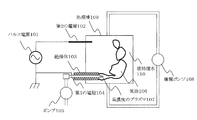
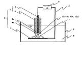
- FIG. 1 is an overall configuration diagram of a liquid processing apparatus in the present embodiment.
- the inside of the treatment tank 109 is filled with water (treated water) 110 that is a liquid to be treated.
- the processing tank 109 has a volume of about 250 milliliters (about 250 cm 3 ).
- a second electrode 102 and a first electrode 104 penetrating the wall are disposed on one wall of the processing tank 109, and one end of each is located in the processing tank 109.
- the first electrode 104 has a cylindrical shape (more specifically, a cylindrical shape) open at both ends, and a pump 105 serving as a gas supply device is connected to the opening at one end.
- Gas is supplied into the processing tank 109 from the opening at the other end of the first electrode 104 by the pump 105.
- the gas supplied from the outside of the processing tank 109 is air, He, Ar, or O 2 .
- the gas is supplied from a gas supply source (not shown) provided separately, or the gas in the atmosphere in which the treatment tank 109 is arranged is supplied as it is.
- the second electrode 102 has a cylindrical shape, and is disposed so that one end thereof is in contact with the water to be treated 110 in the treatment tank 109.
- a pulse voltage or an alternating voltage is applied between the second electrode 102 and the first electrode 104 by the power source 101.
- the treated water 110 is circulated by the circulation pump 108.
- the circulation speed of the water to be treated 110 is set to an appropriate value from the decomposition speed of the substance to be decomposed by plasma and the volume of the treatment tank 109.
- the dimensions of the treatment tank 109 are not particularly limited.
- the size of the processing tank 109 may have a volume of 0.1 liter to 1000 liter.
- the volume of the unit including the power source and the pump is preferably set to 1000 to 5000 cm 3 , for example.
- a volume is preferably designed to be a cube having, for example, length ⁇ width ⁇ height of 100 mm ⁇ 100 mm ⁇ 100 mm to 171 mm ⁇ 171 mm ⁇ 171 mm.
- the shape of the unit consisting of the power source and the pump may have a rectangular parallelepiped shape, or may be another shape.
- the size (ie, volume) of a unit composed of a power source and a pump in the liquid processing apparatus becomes excessively large, the size of the appliance itself increases. Since the liquid processing apparatus of the present invention can efficiently generate plasma, liquid processing can be performed even with a power supply that is small enough to fit in the unit having the above-described volume.
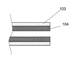
- FIG. 1-2 is an enlarged side sectional view showing the vicinity of the opening of the first electrode 104.
- the first electrode 104 is a cylindrical electrode made of metal and has an inner diameter of 0.4 mm and an outer diameter of 0.6 mm.
- an insulator is in contact with the outer peripheral surface of the first electrode 104 so as not to form a gap between the first electrode 104 and the metal is exposed only at the end surface of the first electrode. .
- the outer peripheral surface of the first electrode 104 is not in direct contact with the water to be treated 110.
- the insulator is formed by directly plasma-spraying titanium oxide on the first electrode 104, and the thickness of the insulator is 0.1 mm. Since titanium oxide has little influence on the human body, it is preferably used as an insulator when the treated liquid is used in human life.
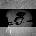
- the first electrode 104 when the gas is continuously supplied into the treated water 110 from the opening of the first electrode 104, bubbles 106 are formed in the treated water 110.
- the bubble 106 is a columnar bubble having a dimension in which the gas therein covers the opening of the first electrode 104, that is, the opening of the electrode 104 is located in the bubble 106. Therefore, in Embodiment 1, the first electrode 104 also functions as a bubble generation unit. As shown in FIG. 1-2, the end face of the opening of the first electrode 104 is not covered with the insulator 103, and the metal as the conductor is exposed.
- the pump 105 By appropriately setting the gas supply amount using the pump 105, the state in which the vicinity of the opening of the first electrode 104 is covered with the gas in the bubble 106 can be maintained.
- An insulator made of titanium oxide is disposed on the outer peripheral surface of the first electrode 104. Therefore, it can be said that the surface of the first electrode 104 is configured so as not to be in direct contact with the water to be treated 110. When an appropriate amount of gas is continuously supplied, the surface of the first electrode 104 is not in direct contact with the water to be treated 110, that is, the conductor constituting the first electrode 104 is in the water to be treated 110. It will be in a state where it is not exposed.
- the first electrode (or the surface of the first electrode) does not directly contact the liquid (water to be treated)” means that the surface of the first electrode is a large lump in the treatment tank. It means no contact with liquid. Therefore, for example, when bubbles are generated from the bubble generating portion in a state where the surface of the first electrode is wet with liquid, the surface of the first electrode remains wet with the liquid (that is, strictly speaking, the first electrode In a state where the surface of one electrode is in contact with the liquid), a state in which the gas in the bubble covers the surface may occur, but this state is also included in the state where the first electrode does not directly contact the liquid Shall.
- gas is supplied into the water 110 to be treated from the opening at one end located in the treatment tank of the first electrode 104 by the pump 105.
- the flow rate of the gas is, for example, 0.5 liter / min to 2.0 liter / min, and in the water to be treated 110, the opening of the first electrode 104 is made of the gas inside thereof as described above. Covering columnar bubbles 106 are formed.
- the bubble 106 is a single large bubble that is not interrupted over a certain distance (20 mm or more in the illustrated form) from the opening of the first electrode 104.
- the periphery of the opening of the first electrode 104 is located in the bubble 106 and can be covered with the gas in the bubble 106.
- the gas 106 in which the gas inside covers the end face of the opening of the first electrode 104 is not “closed” in the liquid because the gas-liquid interface that defines it in the liquid is not closed. It is in contact with the insulator 103 in the vicinity of the part.
- the conductor is exposed only on the end surface of the opening on the outer surface of the first electrode 104. Therefore, by generating the bubble 106, the first electrode 104 is formed by the bubble 106 and the insulator 103.
- the outer surface of 104 is isolated from the treated water 110.
- the inner surface (inner peripheral surface) of the first electrode 104 is covered with the supplied gas when the bubbles 106 are formed, and does not directly contact the water to be treated 110.
- the periphery of the opening of the first electrode 104 is continuously located in the bubble 106 while a voltage is applied between the first electrode 104 and the second electrode 102, that is, in the bubble 106. It is preferable that it is continuously covered with gas. However, if the gas supply amount (flow rate) is small, the periphery of the opening of the first electrode 104 is not located in the bubble 106 and is in direct contact with the treated water 110 even if the gas is continuously supplied. Sometimes. The presence or absence of such contact can be confirmed by photographing the vicinity of the first electrode 104 while supplying bubbles with a high-speed camera every 0.1 ms to 0.5 ms.
- the frequency of contact between the first electrode 104 and the liquid is obtained by taking and observing a photograph with a high-sensitivity camera while continuously supplying gas for 1 to 30 seconds, and determining the electrode coverage according to the following formula. Can know. Whether or not the exposed surface of the conductor of the first electrode is located in the bubble is determined visually in the photograph.
- the gas is preferably supplied so that the electrode coverage is 90% or more, more preferably 94% or more.
- Electrode coverage (%) [(number of images (photos) in which the exposed surface of the conductor of the first electrode is located in bubbles) / total number of captured images (photos)] ⁇ 100
- a voltage is applied between the first electrode 104 and the second electrode 102. That is, a pulse voltage is applied to the first electrode 104 with the second electrode 102 grounded. For example, a pulse voltage having a peak voltage of 4 kV, a pulse width of 1 ⁇ s, and a frequency of 30 kHz may be applied.
- the supplied power is 200 W, for example.
- the distance between the first electrode 104 and the second electrode 102 is not particularly limited.
- the position where the second electrode 102 is disposed is not limited as long as at least a part of the treatment tank 109 is in contact with the water to be treated 110. This is because the entire treated water functions as an electrode because the second electrode 102 is in contact with the treated water 110. That is, it can be considered that the entire surface of the water to be treated 110 in contact with the bubbles 106 functions as an electrode when viewed from the first electrode 104 side.
- the frequency of the pulse voltage there is no particular restriction on the frequency of the pulse voltage, and plasma can be sufficiently generated by applying a pulse voltage of 1 Hz to 30 kHz, for example.
- the voltage is determined not only by the power supply capability but also by the balance with the impedance of the load.
- bipolar pulse voltage when applying a pulse voltage, a positive pulse voltage and a negative pulse voltage are applied alternately, so-called bipolar pulse voltage has an advantage that the life of the electrode is prolonged.
- a power source capable of outputting a voltage of 6 kV without a load is used, and a voltage of 4 kV is actually applied in a state where a load including an electrode is connected as described above. Can do.
- plasma can be formed with little voltage loss.
- the inner diameter of the first electrode 104 is 0.4 mm and the outer diameter is 0.6 mm.
- the inner diameter is 0.07 to 2.0 mm and the outer diameter is 0.1 to 3.0 mm. Even if it exists, plasma can be formed.
- the dimension (length) of the first electrode 104 in the treatment tank 109 is not particularly limited.
- the first electrode 104 having an inner diameter and an outer diameter in the above ranges may have a length of 0.1 to 25 mm in the processing tank 109. In the present embodiment, the length of the portion of the first electrode 104 located in the treatment tank 109 is approximately 10 mm.
- the bubbles 106 formed near the opening of the first electrode 104 spread in the direction toward the wall of the treatment tank 109. Inability to do so (impacts on the wall), the area of the gas-liquid interface tends to be small, and the amount of plasma generated tends to be small. However, the plasma is generated as long as the first electrode 104 is located in the treatment tank 109. As described above, in the liquid processing apparatus of the present embodiment, the tolerance for the size of the electrode is widened.
- FIG. 2 is a graph showing the results of measuring the light emission characteristics of plasma in this embodiment with a spectrometer. This is the result when tap water is used as the water to be treated 110, the water temperature is 26.5 ° C., and the conductivity is 20.3 mS / m. As shown in FIG. 2, light emission due to OH radicals generated by the decomposition of water is observed. Further, emission of N 2 , N, H, and O is also observed. The light emission of N 2 and N is because air is supplied into the water to be treated 110 as a gas. Thus, in the present embodiment, plasma having both the characteristics of plasma formed in water and the characteristics of plasma formed in the atmosphere is generated.
- an indigo carmine aqueous solution is used as a model of the liquid to be processed.
- Indigo carmine is a water-soluble organic substance and is often used as a model for treating polluted water.
- the concentration of the indigo carmine aqueous solution used in the present embodiment was 10 mg / liter, and the volume of the water to be treated 110 was 250 milliliters.
- OH radicals, N radicals, N 2 radicals, H radicals, and O radicals are generated. These radicals act on indigo carmine and break down the indigo carmine molecule by breaking intramolecular bonds.
- the OH radical has an oxidation potential of 2.81 eV, which is larger than the oxidation potential of ozone and chlorine. Therefore, OH radicals can decompose not only indigo carmine but also many organic substances.
- the O radical and N radical also have carbon binding energies of 1076 kJ / mol and 750 kJ / mol, respectively, which are higher than the CC binding energy of 618 kJ / mol and the CH binding energy of 338 kJ / mol. Much bigger. Therefore, they greatly contribute to the degradation of indigo carmine molecules.
- N and N 2 ions are generated by plasma due to the supply of air to generate bubbles 106, which collide with indigo carmine molecules. The collision between these ions weakens the intermolecular bond of the indigo carmine molecule, so that the decomposition effect by the OH radical, O radical, and N radical becomes greater.
- FIG. 3 is a graph showing the results of measuring the change in absorbance of the indigo carmine aqueous solution with respect to the treatment time.
- the absorbance value in FIG. 3 is a value normalized with the untreated absorbance as 1.
- the result by the liquid processing apparatus of this Embodiment is shown with a white circle.
- Comparative Examples 1 and 2 the results of the conventional liquid processing apparatus are indicated by black squares and black triangles.
- both the first electrode 104 and the second electrode 102 are made of cylindrical tungsten having an outer diameter of 0.16 mm, and the end faces of these electrodes are indigo. It was made to oppose in the carmine solution at intervals of 2 mm.
- the processing result by this apparatus is shown by a black square.
- the absorbance when the same electrode configuration is employed and fine bubbles (diameter of about 0.3 mm) are continuously supplied between the first electrode 104 and the second electrode 102 from a separately provided nozzle. This change is indicated by a black triangle as Comparative Example 2.
- the power supplied to the first electrode 104 was set to 200 W as in the liquid treatment apparatus of this embodiment.
- the indigo carmine aqueous solution could be almost completely decomposed in about 16 minutes. This can be achieved by efficiently generating OH radicals.
- Comparative Example 1 it takes about 190 minutes to almost completely decompose the indigo carmine aqueous solution.
- Comparative Example 2 in which bubbles are interposed between the electrodes in the conventional liquid processing apparatus, it takes about 50 minutes.
- plasma can be generated efficiently even with the same input power, and liquid processing can be performed in a short time.
- the conventional liquid processing apparatus as a comparative example can be considered as follows.
- Comparative Example 1 in which two electrodes are opposed to each other with a spacing of 2 mm, plasma is generated in a space of about 0.04 mm 3 between the electrodes, and thus it is considered that the amount of generated radicals is small.
- the bubbles are not always generated, and when the bubbles move by buoyancy, the plasma disappears accordingly. Then, a new bubble is generated between the electrodes, and plasma is repeatedly generated inside the bubble.
- plasma can be generated simply by applying a voltage in a pulsed manner with a narrow electrode interval, but plasma generation is not possible due to the intermittent generation of plasma and the narrow space in which plasma is generated. It is not done efficiently. For this reason, it is considered that the decomposition time of the indigo carmine molecule is increased.
- the liquid processing apparatus of this embodiment can generate more plasma than when bubbles are supplied from the outside, and the decomposition time of indigo carmine molecules is reduced to one third or less. It has the remarkable effect of being able to. This is considered to be because the gas is continuously supplied from the end portion of the first electrode 104 to the water to be treated 110 at a relatively large flow rate in the present embodiment.
- iron is used as a material for the second electrode 102 and the first electrode 104.
- These electrodes may be formed using tungsten, copper, aluminum, or the like.
- the insulator provided on the outer peripheral surface of the first electrode 104 may be formed by spraying yttrium oxide. Since yttrium oxide has a higher plasma resistance than titanium oxide, the use of yttrium oxide has the effect of extending the electrode life.
- the change in the time required for the blue color of the indigo carmine aqueous solution to disappear is observed by changing the power supply.
- the gas flow rate was set to 2000 ml / min. Further, by applying a pulse voltage having a peak voltage of 4 kV, a pulse width of 500 ⁇ s, a frequency of 100 Hz, and a supply power of 30 W between the first electrode 104 and the second electrode 102, indigomin molecules in the aqueous solution are applied. The time required to decompose was measured.
- a pulse voltage having a pulse width of 500 ⁇ s, a frequency of 100 Hz, and a supply power of 6 W is applied between the first electrode 104 and the second electrode 102 to decompose indigomin molecules in the aqueous solution.
- the time required was measured. The results are shown in FIG.
- a power source having a different specification was used.
- the smaller the supply power the longer the time required for decomposition, but plasma was generated even when the supply power was about 30 W and 6 W, and the decomposition proceeded.
- the supplied power is 6 W, it is estimated that the time required for all the indigomin molecules in the aqueous solution to decompose is about 150 minutes. This is more than the same time when the supplied power is 200 W in Comparative Example 1. It was short.
- the liquid processing apparatus of the present invention enables liquid processing with a small power supply. Therefore, the liquid processing apparatus of the present invention does not require high power (4000 W or more) as required in the apparatuses of Patent Documents 1 and 6.
- the power source may be a power source whose maximum output capacity is greater than 0 W and less than 1000 W, and it is not necessary to supply power exceeding 1000 W.
- Such electric power can be obtained from the power source of household electric appliances. Therefore, the liquid processing apparatus of the present invention is suitable for incorporation into household electric appliances from the viewpoint of supply power, and the unit composed of a power source and a pump has a small size having the aforementioned volume (1000 to 5000 cm 3 ). It is also possible to do.
- the discharge between the electrodes is a corona to glow discharge.
- plasma is generated by glow discharge, it consumes less power and does not require a large current as compared with abnormal glow discharge or arc discharge, so that the electrode is less deteriorated and the capacity of the power source is also reduced. For this reason, there exists an advantage that an apparatus price and a maintenance cost also become low.
- the electrode to which voltage is applied is not positioned in the liquid, but is placed on the liquid level, the ground electrode is positioned in the liquid, discharge is performed, and plasma is generated on the liquid level.
- the method is known. This method is common to the present invention in that the electrode to which the voltage is applied is not in direct contact with the liquid. However, when plasma is generated by this method, ozone is generated. Ozone is an undesirable product. Furthermore, in this method, the area of the plasma in contact with the liquid tends to be narrow, and the amount of OH radicals generated is small.
- FIG. 4 is an overall configuration diagram of the liquid processing apparatus in the present embodiment.
- the present embodiment is different from the first embodiment in that cylindrical alumina ceramics are used as the insulator 103.
- Other configurations are the same as those of the first embodiment.
- FIG. 4-2 is an enlarged view of the vicinity of the opening of the first electrode 104.
- a cylindrical insulator 103 made of alumina ceramic and having an inner diameter of 0.6 mm and an outer diameter of 0.9 mm is disposed in close contact with the outer peripheral surface of the first electrode 104.
- the insulator 103 is configured to be slidable with respect to the first electrode 104. In this embodiment mode, the positional relationship between the end surfaces of the first electrode 104 and the insulator 103 is changed, and the influence on the processing time of the liquid to be processed is examined. As shown in FIG.
- the distance between the tip of the insulator 103 and the tip of the first electrode 104 is d, and the tip of the first electrode 104 is based on the tip position of the insulator 103.
- D is positive when protruding outward, and d is negative when retracting inward.
- the air of 2000 ml / min was supplied from the pump.
- the second electrode 102 was grounded, and a pulse voltage having a peak voltage of 4 kV, a pulse width of 1 ⁇ s, a frequency of 30 kHz, and a supplied power of 200 W was applied to the first electrode 104.
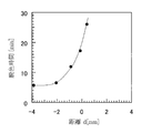
- the graph in FIG. 5 shows the relationship between the distance d and the time until the indigo carmine aqueous solution is completely decolorized.
- the decolorization time decreases rapidly as the distance d changes from positive to negative, and the decomposition of indigo carmine proceeds.
- the decolorization time is greatly reduced. This is because the tip of the first electrode 104 is more easily covered with the supplied gas when the tip of the first electrode 104 is retracted than the tip of the insulator 103.
- the bubble 106 and the insulator 103 are interposed between the first electrode 104 and the water to be treated 110, so that the first electrode 104 is treated water. 110 will not be in direct contact. As a result, there is no current path consisting only of the water to be treated 110 between the first electrode 104 and the second electrode 102. Therefore, since the pulse voltage applied to the first electrode 104 is applied to the bubble 106 without leaking into the water to be treated 110, plasma can be generated efficiently.
- the decolorization time does not change much.
- the distance d is set to -4 mm or less, the distance between the gas and water becomes longer and it becomes difficult to discharge, so that it becomes difficult for the plasma to decompose water and the amount of OH radicals decreases. In this way, it is not just that the end face of the first electrode 104 needs to be away from the water 110 to be treated, but the optimum distance d is determined according to the gas supply amount, the size and shape of the first electrode, and the like. Value exists.
- the decoloring time did not increase. This is because the generation of plasma is started in a state where the bubbles 106 are once formed in the water to be treated 110 and the vicinity of the opening of the first electrode 104 is located in the bubbles 106 and covered with the gas in the bubbles 106. It is thought that.
- Moving the first electrode 104 relative to the insulator 103 to make d negative the first electrode 104 is less likely to get wet with water, so that the voltage loss is small and stable, The effect of stable discharge is obtained.
- Moving the first electrode 104 relative to the insulator 103 may be performed by moving the insulator 103 or may be performed by moving the first electrode 104.
- the surface of the bubble is smaller than that in the first embodiment shown in FIG. It is not smooth, and many irregularities are generated on the surface due to shock waves caused by plasma. At the same time, some of the bubbles are separated by the shock wave, and microbubbles 111 are generated. This is because a higher voltage is instantaneously applied to the gas-liquid interface because the end face of the first electrode 104 has moved away from the water to be treated 110.
- FIG. 6 is a configuration diagram of the liquid processing apparatus in the present embodiment.
- the second electrode 202 is disposed so that a part of the second electrode 202 is in contact with the bubble 206 or a part of the second electrode 202 is located inside the bubble 206.
- Other configurations are the same as those of the first embodiment.
- reference numerals in FIG. 6 reference numerals having the same last two digits as the last two digits in FIG. 1 are the same elements or members as the elements or members indicated by those reference numerals in FIG. 1.
- the air of 2000 ml / min was supplied from the pump.
- the second electrode 202 was grounded, and a pulse voltage having a peak voltage of 4 kV, a pulse width of 1 ⁇ s, a frequency of 30 kHz, and a supply power of 200 W was applied to the first electrode 204.
- the surface of the bubble 206 is not smooth, and a lot of irregularities are generated on the surface due to shock waves caused by plasma. .
- some of the bubbles are separated by the shock wave, and microbubbles 211 are generated.
- the number of generated microbubbles is overwhelmingly large.
- FIG. 7 is a graph showing the results of measuring the change in absorbance of the indigo carmine aqueous solution with respect to the treatment time in the present embodiment.
- white squares are the measurement results of the present embodiment.
- White circles are the measurement results of the first embodiment.
- a power of 200 W was supplied between the first electrodes 204 and 104 and the second electrodes 202 and 102, respectively.
- the time until the indigo carmine aqueous solution was completely decomposed was about 3 minutes 30 seconds.
- the time until the indigo carmine aqueous solution was completely decomposed was about 16 minutes. That is, according to the configuration of the present embodiment, it can be seen that the processing time can be shortened to a quarter or less of the processing time required by the configuration of the first embodiment. This is because the electrode 202 is in contact with or in the bubble, so that the voltage is not lost (that is, the current does not escape into the liquid), and a stronger voltage is applied between the air in the bubble and the bubble and the solution. This is because it is applied to the interface.
- the plasma density is increased, more O and H radicals are generated as shown in FIG. 8, and the process is completed in a shorter time.
- a shock wave generated by a strong electric field acts on the interface between the bubble and the solution, and a part of the bubble is separated to generate a microbubble.
- These microbubbles contain OH radicals and O radicals, and these radicals are widely propagated throughout the solution by the microbubbles, so that the decomposition of indigo carmine can be further promoted.
- the insulator 203 is a cylindrical alumina ceramic that is movable with respect to the electrode 204, and the positions of the end face of the first electrode 204 and the end face of the insulator 203 are as follows. The relationship was changed to observe the effect of the liquid to be processed on the processing time.
- the end face of the first electrode 204 was set approximately 2 mm inside from the end face of the insulator 203, and plasma was generated to measure the absorbance of the liquid to be processed.
- Figure 7-2 shows the results. As shown in FIG. 7-2, it can be seen that the modification of the present embodiment further shortens the decolorization time compared to the second embodiment. From this result, it can be said that a stronger voltage is applied to the air and the bubble-solution interface in the bubble without the voltage being lost when the second electrode 202 is in contact with or in the bubble.
- the first electrode is cylindrical (more specifically, cylindrical), the gas is supplied from the gas supply device to the first electrode, and the gas is liquidated from the opening of the first electrode.
- a method of forming bubbles by supplying them inside was described.
- the bubble generation unit may be provided independently of the first electrode.
- the bubble generating unit generates bubbles that cover at least the surface where the conductor is exposed, among the surfaces located in the liquid of the first electrode, that is, the surface is located in the bubbles.
- the flow rate of the gas sent to the bubble generating unit, the size of the bubble generating unit (for example, the inner diameter of the bubble generating unit if the bubble generating unit is cylindrical), the position of the bubble generating unit, etc. are appropriately selected. Is formed. Since the bubbles generated in the liquid move from the bottom to the top due to buoyancy, for example, when the bubble generating part is installed below the first electrode, the gas in the bubbles easily covers the surface of the first electrode.
- the first electrode is cylindrical, and the outer peripheral surface of the first electrode is covered with an insulator so that the outer peripheral surface of the first electrode is not exposed in the liquid. Therefore, the region to be covered by the gas in the bubble may be only near the opening (end surface) of the first electrode. Therefore, the effect of the present invention can be obtained relatively easily by using the first electrode having such a configuration.
- the first electrode may not be covered with an insulator, and in that case, the entire surface of the first electrode located in the liquid is a gas in a bubble. A bubble generating part is provided so as to be covered.
- the insulator may cover only a part of the outer peripheral surface of the first electrode, in which case the surface of the first electrode that is not covered with the insulator is a bubble. It needs to be covered with the gas inside.
- a circulation pump for circulating the water to be treated is provided.
- a circulation pump is not always necessary.
- the generation of bubbles naturally causes the circulation of the liquid in the treatment tank, and further the circulation of the liquid is promoted by the generation of microbubbles.
- the entire water to be treated can be treated with plasma.
- a film for preventing corrosion of the electrode may be formed on the first electrode.
- the corrosion prevention film is formed by selecting the material and the thickness so as not to prevent the discharge between the first electrode and the second electrode in consideration of the material constituting the electrode and the voltage applied to the electrode. Is done. Even if such a film is formed on the surface of the conductor of the first electrode, the effects of the present invention can be obtained and belong to the claims of the present application.
- the liquid processing apparatus of the present invention is suitable for decomposing chemical substances present in liquids, destroying microorganisms, sterilizing, etc., and can be used with various products, particularly electric products, or incorporated into electric products (that is, built-in). Can be used). Electrical products include water purification devices, air conditioners and humidifiers, as well as ship ballast water treatment devices, electric razor washers, washing machines and dishwashers. The water purification device, the air conditioner, the humidifier, the washing machine, the electric razor washer, and the dishwasher may be for home use. According to the liquid processing apparatus of the present invention, the liquid can be processed even with low electric power, so that the liquid processing apparatus can be operated using the power source of household electrical equipment.
- the liquid treatment apparatus according to the present invention is useful as a water purification apparatus for sewage treatment, for example.
- Treatment tank 110 210 Water to be treated 111, 211 Microbubble
Landscapes
- Chemical & Material Sciences (AREA)
- Chemical Kinetics & Catalysis (AREA)
- Organic Chemistry (AREA)
- Electrochemistry (AREA)
- General Chemical & Material Sciences (AREA)
- Life Sciences & Earth Sciences (AREA)
- Hydrology & Water Resources (AREA)
- Engineering & Computer Science (AREA)
- Environmental & Geological Engineering (AREA)
- Water Supply & Treatment (AREA)
- Toxicology (AREA)
- General Health & Medical Sciences (AREA)
- Health & Medical Sciences (AREA)
- Water Treatment By Electricity Or Magnetism (AREA)
Abstract
Cette invention utilise une première électrode (104) dont une partie au moins se trouve à l'intérieur d'une cuve de traitement (109) renfermant un liquide (110), une seconde électrode (102) dont une partie au moins se trouve à l'intérieur de la cuve de traitement, une unité génératrice de bulles qui génère des bulles (106) dans le liquide quand le liquide se trouve dans la cuve de traitement et qui génère les bulles (106) de sorte qu'une surface au moins sur laquelle un conducteur est exposé, parmi les surfaces de la première électrode (104) qui se trouvent dans la cuve de traitement, se trouve au milieu des bulles (106), un dispositif d'alimentation en gaz (105) qui alimente en gaz, en une quantité nécessaire pour générer les bulles, l'unité génératrice de bulles depuis l'extérieur de la cuve de traitement, et une alimentation électrique (101) qui applique une tension à la première électrode et à la seconde électrode.
Priority Applications (1)
| Application Number | Priority Date | Filing Date | Title |
|---|---|---|---|
| US14/113,370 US20140054242A1 (en) | 2011-05-17 | 2011-12-26 | Liquid treating apparatus and liquid treating method |
Applications Claiming Priority (2)
| Application Number | Priority Date | Filing Date | Title |
|---|---|---|---|
| JP2011110169 | 2011-05-17 | ||
| JP2011-110169 | 2011-05-17 |
Publications (1)
| Publication Number | Publication Date |
|---|---|
| WO2012157034A1 true WO2012157034A1 (fr) | 2012-11-22 |
Family
ID=47176404
Family Applications (1)
| Application Number | Title | Priority Date | Filing Date |
|---|---|---|---|
| PCT/JP2011/007272 Ceased WO2012157034A1 (fr) | 2011-05-17 | 2011-12-26 | Dispositif de traitement de liquide et procédé de traitement de liquide |
Country Status (2)
| Country | Link |
|---|---|
| US (1) | US20140054242A1 (fr) |
| WO (1) | WO2012157034A1 (fr) |
Cited By (17)
| Publication number | Priority date | Publication date | Assignee | Title |
|---|---|---|---|---|
| US20140168644A1 (en) * | 2012-06-28 | 2014-06-19 | Panasonic Corporation | Apparatus for analyzing elements in liquid |
| WO2014152844A1 (fr) * | 2013-03-14 | 2014-09-25 | North Carolina State University | Sources de plasma atmosphérique entraînées à très haute fréquence (thf) et irrigation fertilisante au point d'utilisation par production plasma d'espèces portant de l'azote |
| WO2014185051A1 (fr) * | 2013-05-14 | 2014-11-20 | パナソニックIpマネジメント株式会社 | Dispositif de traitement de liquide, procédé de traitement de liquide et liquide traité par plasma |
| CN104556318A (zh) * | 2013-10-25 | 2015-04-29 | 松下知识产权经营株式会社 | 液体处理装置以及液体处理方法 |
| CN104649378A (zh) * | 2013-11-18 | 2015-05-27 | 松下电器产业株式会社 | 液体处理装置及液体处理方法 |
| CN104645370A (zh) * | 2013-11-18 | 2015-05-27 | 松下知识产权经营株式会社 | 液体处理单元、冲洗坐便盖、洗衣机及液体处理装置 |
| CN104649372A (zh) * | 2013-11-18 | 2015-05-27 | 松下知识产权经营株式会社 | 液体处理单元、冲洗坐便盖、洗衣机及液体处理装置 |
| CN104649379A (zh) * | 2013-11-18 | 2015-05-27 | 松下知识产权经营株式会社 | 液体处理装置 |
| US20150251933A1 (en) * | 2012-11-13 | 2015-09-10 | Mitsubishi Electric Corporation | Water treatment device and water treatment method |
| WO2015154711A1 (fr) * | 2014-04-12 | 2015-10-15 | 大连双迪创新科技研究院有限公司 | Dispositif de nettoyage auxiliaire pour purificateur d'eau |
| JPWO2014017020A1 (ja) * | 2012-07-24 | 2016-07-07 | パナソニックIpマネジメント株式会社 | 液体処理装置及び液体処理方法 |
| JPWO2014171138A1 (ja) * | 2013-04-18 | 2017-02-16 | パナソニックIpマネジメント株式会社 | 液体処理装置及び液体処理方法 |
| JP2017144425A (ja) * | 2016-02-17 | 2017-08-24 | パナソニックIpマネジメント株式会社 | 液体処理装置 |
| JP2017192995A (ja) * | 2016-04-19 | 2017-10-26 | 不二越機械工業株式会社 | ノズルおよびワーク研磨装置 |
| US9856144B2 (en) * | 2014-08-08 | 2018-01-02 | Panasonic Intellectual Property Management Co., Ltd. | Nitrous acid generator |
| JP2019166508A (ja) * | 2018-03-26 | 2019-10-03 | 日本碍子株式会社 | 殺菌水を生成する装置、被処理物を殺菌する方法及び殺菌水を生成する方法 |
| CN115647494A (zh) * | 2022-11-17 | 2023-01-31 | 北京科技大学 | 电火花加工过程中气泡时空控制及观测系统 |
Families Citing this family (9)
| Publication number | Priority date | Publication date | Assignee | Title |
|---|---|---|---|---|
| US11279633B2 (en) | 2014-09-15 | 2022-03-22 | Onvector Llc | System and method for plasma discharge in liquid |
| US12295090B2 (en) | 2014-09-15 | 2025-05-06 | Onvector Llc | System and method for plasma discharge in liquid |
| WO2016044239A1 (fr) * | 2014-09-15 | 2016-03-24 | Energy Onvector, LLC | Système et procédé pour une décharge de plasma dans un liquide |
| US10703653B2 (en) * | 2016-02-17 | 2020-07-07 | Panasonic Intellectual Property Management Co., Ltd. | Liquid treatment device utilizing plasma |
| JP6643649B2 (ja) * | 2016-03-31 | 2020-02-12 | パナソニックIpマネジメント株式会社 | プラズマ生成装置 |
| CN108117135A (zh) * | 2016-11-28 | 2018-06-05 | 松下知识产权经营株式会社 | 液体处理装置 |
| JP2018131659A (ja) * | 2017-02-16 | 2018-08-23 | アークレイ株式会社 | 電気分解装置 |
| WO2019006323A1 (fr) * | 2017-06-30 | 2019-01-03 | Ohio University | Décontamination de fluides par un chauffage par effet joule |
| CN113293099B (zh) * | 2021-06-01 | 2023-12-22 | 中国科学院重庆绿色智能技术研究院 | 研究微纳米气泡与细胞相互作用的方法 |
Citations (2)
| Publication number | Priority date | Publication date | Assignee | Title |
|---|---|---|---|---|
| JP2005058887A (ja) * | 2003-08-11 | 2005-03-10 | Mitsubishi Heavy Ind Ltd | 高電圧パルスを利用した廃水処理装置 |
| JP2007207540A (ja) * | 2006-02-01 | 2007-08-16 | Kurita Seisakusho:Kk | 液中プラズマ発生方法、液中プラズマ発生装置、被処理液浄化装置及びイオン液体供給装置 |
Family Cites Families (4)
| Publication number | Priority date | Publication date | Assignee | Title |
|---|---|---|---|---|
| US5626726A (en) * | 1995-09-27 | 1997-05-06 | Lockheed Idaho Technologies Company | Method for cracking hydrocarbon compositions using a submerged reactive plasma system |
| US6749759B2 (en) * | 2002-07-12 | 2004-06-15 | Wisconsin Alumni Research Foundation | Method for disinfecting a dense fluid medium in a dense medium plasma reactor |
| US9011697B2 (en) * | 2006-06-16 | 2015-04-21 | Drexel University | Fluid treatment using plasma technology |
| EP2206521B1 (fr) * | 2007-09-27 | 2019-07-17 | Satoshi Ikawa | Appareil de stérilisation |
-
2011
- 2011-12-26 WO PCT/JP2011/007272 patent/WO2012157034A1/fr not_active Ceased
- 2011-12-26 US US14/113,370 patent/US20140054242A1/en not_active Abandoned
Patent Citations (2)
| Publication number | Priority date | Publication date | Assignee | Title |
|---|---|---|---|---|
| JP2005058887A (ja) * | 2003-08-11 | 2005-03-10 | Mitsubishi Heavy Ind Ltd | 高電圧パルスを利用した廃水処理装置 |
| JP2007207540A (ja) * | 2006-02-01 | 2007-08-16 | Kurita Seisakusho:Kk | 液中プラズマ発生方法、液中プラズマ発生装置、被処理液浄化装置及びイオン液体供給装置 |
Cited By (28)
| Publication number | Priority date | Publication date | Assignee | Title |
|---|---|---|---|---|
| US9677940B2 (en) * | 2012-06-28 | 2017-06-13 | Panasonic Intellectual Property Management Co., Ltd. | Apparatus for analyzing elements in liquid with controlled amount of gas supply for plasma generation |
| US20140168644A1 (en) * | 2012-06-28 | 2014-06-19 | Panasonic Corporation | Apparatus for analyzing elements in liquid |
| JPWO2014017020A1 (ja) * | 2012-07-24 | 2016-07-07 | パナソニックIpマネジメント株式会社 | 液体処理装置及び液体処理方法 |
| US9688549B2 (en) | 2012-07-24 | 2017-06-27 | Panasonic Intellectual Property Management Co., Ltd. | Liquid treatment device and liquid treatment method |
| US9957170B2 (en) * | 2012-11-13 | 2018-05-01 | Mitsubishi Electric Corporation | Water treatment device and water treatment method |
| US20150251933A1 (en) * | 2012-11-13 | 2015-09-10 | Mitsubishi Electric Corporation | Water treatment device and water treatment method |
| WO2014152844A1 (fr) * | 2013-03-14 | 2014-09-25 | North Carolina State University | Sources de plasma atmosphérique entraînées à très haute fréquence (thf) et irrigation fertilisante au point d'utilisation par production plasma d'espèces portant de l'azote |
| US9475710B2 (en) | 2013-03-14 | 2016-10-25 | North Carolina State University | Very high frequency (VHF) driven atmospheric plasma sources and point of use fertigation of irrigation water utilizing plasma production of nitrogen bearing species |
| US9814127B2 (en) | 2013-04-18 | 2017-11-07 | Panasonic Intellectual Property Management Co., Ltd. | Liquid treatment device and liquid treatment method |
| JPWO2014171138A1 (ja) * | 2013-04-18 | 2017-02-16 | パナソニックIpマネジメント株式会社 | 液体処理装置及び液体処理方法 |
| US9540256B2 (en) | 2013-05-14 | 2017-01-10 | Panasonic Intellectual Property Management Co., Ltd. | Liquid treatment device, liquid treatment method, and plasma treatment liquid |
| JP5906444B2 (ja) * | 2013-05-14 | 2016-04-20 | パナソニックIpマネジメント株式会社 | 液体処理装置、液体処理方法及びプラズマ処理液 |
| WO2014185051A1 (fr) * | 2013-05-14 | 2014-11-20 | パナソニックIpマネジメント株式会社 | Dispositif de traitement de liquide, procédé de traitement de liquide et liquide traité par plasma |
| US9969627B2 (en) | 2013-10-25 | 2018-05-15 | Panasonic Intellectual Property Management Co., Ltd. | Liquid treatment apparatus and liquid treatment method |
| CN104556318A (zh) * | 2013-10-25 | 2015-04-29 | 松下知识产权经营株式会社 | 液体处理装置以及液体处理方法 |
| CN104649372A (zh) * | 2013-11-18 | 2015-05-27 | 松下知识产权经营株式会社 | 液体处理单元、冲洗坐便盖、洗衣机及液体处理装置 |
| CN104645370A (zh) * | 2013-11-18 | 2015-05-27 | 松下知识产权经营株式会社 | 液体处理单元、冲洗坐便盖、洗衣机及液体处理装置 |
| CN104649378A (zh) * | 2013-11-18 | 2015-05-27 | 松下电器产业株式会社 | 液体处理装置及液体处理方法 |
| CN104649379A (zh) * | 2013-11-18 | 2015-05-27 | 松下知识产权经营株式会社 | 液体处理装置 |
| CN104649379B (zh) * | 2013-11-18 | 2016-09-28 | 松下知识产权经营株式会社 | 液体处理装置 |
| WO2015154711A1 (fr) * | 2014-04-12 | 2015-10-15 | 大连双迪创新科技研究院有限公司 | Dispositif de nettoyage auxiliaire pour purificateur d'eau |
| US9856144B2 (en) * | 2014-08-08 | 2018-01-02 | Panasonic Intellectual Property Management Co., Ltd. | Nitrous acid generator |
| JP2017144425A (ja) * | 2016-02-17 | 2017-08-24 | パナソニックIpマネジメント株式会社 | 液体処理装置 |
| JP2017192995A (ja) * | 2016-04-19 | 2017-10-26 | 不二越機械工業株式会社 | ノズルおよびワーク研磨装置 |
| CN107303653A (zh) * | 2016-04-19 | 2017-10-31 | 不二越机械工业株式会社 | 喷嘴和工件研磨装置 |
| US10636685B2 (en) | 2016-04-19 | 2020-04-28 | Fujikoshi Machinery Corp. | Nozzle and work polishing apparatus |
| JP2019166508A (ja) * | 2018-03-26 | 2019-10-03 | 日本碍子株式会社 | 殺菌水を生成する装置、被処理物を殺菌する方法及び殺菌水を生成する方法 |
| CN115647494A (zh) * | 2022-11-17 | 2023-01-31 | 北京科技大学 | 电火花加工过程中气泡时空控制及观测系统 |
Also Published As
| Publication number | Publication date |
|---|---|
| US20140054242A1 (en) | 2014-02-27 |
Similar Documents
| Publication | Publication Date | Title |
|---|---|---|
| WO2012157034A1 (fr) | Dispositif de traitement de liquide et procédé de traitement de liquide | |
| US9688549B2 (en) | Liquid treatment device and liquid treatment method | |
| JP5362934B2 (ja) | プラズマ発生装置およびプラズマ発生方法 | |
| JP5884074B2 (ja) | 液体処理装置及び液体処理方法 | |
| JP6097942B2 (ja) | 液体処理装置及び液体処理方法 | |
| JP5821020B2 (ja) | 液体処理装置及び液体処理方法 | |
| JP5906444B2 (ja) | 液体処理装置、液体処理方法及びプラズマ処理液 | |
| JP5899455B2 (ja) | 液体処理装置及び液体処理方法 | |
| JP6544623B2 (ja) | 処理液生成装置および処理液生成方法 | |
| JP2015136644A (ja) | 液体処理装置及び液体処理方法、ならびにプラズマ処理液 | |
| KR101479261B1 (ko) | 액체 공급 장치 및 이를 이용한 플라즈마 수처리 장치 | |
| JP2003340454A (ja) | プラズマ殺菌装置及びプラズマ殺菌清涼水器 | |
| KR101280445B1 (ko) | 물 정화를 위한 수중 방전 장치 | |
| WO2019003484A1 (fr) | Dispositif de traitement de liquide | |
| KR20100073320A (ko) | 액체상에서의 플라즈마 방전장치 | |
| JP2016004637A (ja) | プラズマ生成装置 | |
| JP2013215682A (ja) | 水処理方法及びこの水処理方法に用いる水処理装置 | |
| KR101599733B1 (ko) | 플라즈마를 이용한 액체 처리 장치 |
Legal Events
| Date | Code | Title | Description |
|---|---|---|---|
| 121 | Ep: the epo has been informed by wipo that ep was designated in this application |
Ref document number: 11865836 Country of ref document: EP Kind code of ref document: A1 |
|
| WWE | Wipo information: entry into national phase |
Ref document number: 14113370 Country of ref document: US |
|
| NENP | Non-entry into the national phase |
Ref country code: DE |
|
| 122 | Ep: pct application non-entry in european phase |
Ref document number: 11865836 Country of ref document: EP Kind code of ref document: A1 |
|
| NENP | Non-entry into the national phase |
Ref country code: JP |