WO2012157111A1 - Correction device for air/fuel ratio sensor - Google Patents
Correction device for air/fuel ratio sensor Download PDFInfo
- Publication number
- WO2012157111A1 WO2012157111A1 PCT/JP2011/061532 JP2011061532W WO2012157111A1 WO 2012157111 A1 WO2012157111 A1 WO 2012157111A1 JP 2011061532 W JP2011061532 W JP 2011061532W WO 2012157111 A1 WO2012157111 A1 WO 2012157111A1
- Authority
- WO
- WIPO (PCT)
- Prior art keywords
- fuel ratio
- air
- output
- sensor
- catalyst
- Prior art date
- Legal status (The legal status is an assumption and is not a legal conclusion. Google has not performed a legal analysis and makes no representation as to the accuracy of the status listed.)
- Ceased
Links
Images

Classifications
-
- F—MECHANICAL ENGINEERING; LIGHTING; HEATING; WEAPONS; BLASTING
- F02—COMBUSTION ENGINES; HOT-GAS OR COMBUSTION-PRODUCT ENGINE PLANTS
- F02D—CONTROLLING COMBUSTION ENGINES
- F02D41/00—Electrical control of supply of combustible mixture or its constituents
- F02D41/24—Electrical control of supply of combustible mixture or its constituents characterised by the use of digital means
- F02D41/2406—Electrical control of supply of combustible mixture or its constituents characterised by the use of digital means using essentially read only memories
- F02D41/2425—Particular ways of programming the data
- F02D41/2429—Methods of calibrating or learning
- F02D41/2451—Methods of calibrating or learning characterised by what is learned or calibrated
- F02D41/2474—Characteristics of sensors
-
- F—MECHANICAL ENGINEERING; LIGHTING; HEATING; WEAPONS; BLASTING
- F01—MACHINES OR ENGINES IN GENERAL; ENGINE PLANTS IN GENERAL; STEAM ENGINES
- F01N—GAS-FLOW SILENCERS OR EXHAUST APPARATUS FOR MACHINES OR ENGINES IN GENERAL; GAS-FLOW SILENCERS OR EXHAUST APPARATUS FOR INTERNAL-COMBUSTION ENGINES
- F01N3/00—Exhaust or silencing apparatus having means for purifying, rendering innocuous, or otherwise treating exhaust
- F01N3/08—Exhaust or silencing apparatus having means for purifying, rendering innocuous, or otherwise treating exhaust for rendering innocuous
- F01N3/10—Exhaust or silencing apparatus having means for purifying, rendering innocuous, or otherwise treating exhaust for rendering innocuous by thermal or catalytic conversion of noxious components of exhaust
- F01N3/18—Exhaust or silencing apparatus having means for purifying, rendering innocuous, or otherwise treating exhaust for rendering innocuous by thermal or catalytic conversion of noxious components of exhaust characterised by methods of operation; Control
-
- F—MECHANICAL ENGINEERING; LIGHTING; HEATING; WEAPONS; BLASTING
- F02—COMBUSTION ENGINES; HOT-GAS OR COMBUSTION-PRODUCT ENGINE PLANTS
- F02D—CONTROLLING COMBUSTION ENGINES
- F02D41/00—Electrical control of supply of combustible mixture or its constituents
- F02D41/02—Circuit arrangements for generating control signals
- F02D41/021—Introducing corrections for particular conditions exterior to the engine
- F02D41/0235—Introducing corrections for particular conditions exterior to the engine in relation with the state of the exhaust gas treating apparatus
-
- F—MECHANICAL ENGINEERING; LIGHTING; HEATING; WEAPONS; BLASTING
- F02—COMBUSTION ENGINES; HOT-GAS OR COMBUSTION-PRODUCT ENGINE PLANTS
- F02D—CONTROLLING COMBUSTION ENGINES
- F02D41/00—Electrical control of supply of combustible mixture or its constituents
- F02D41/02—Circuit arrangements for generating control signals
- F02D41/14—Introducing closed-loop corrections
- F02D41/1438—Introducing closed-loop corrections using means for determining characteristics of the combustion gases; Sensors therefor
- F02D41/1439—Introducing closed-loop corrections using means for determining characteristics of the combustion gases; Sensors therefor characterised by the position of the sensor
- F02D41/1441—Plural sensors
-
- F—MECHANICAL ENGINEERING; LIGHTING; HEATING; WEAPONS; BLASTING
- F02—COMBUSTION ENGINES; HOT-GAS OR COMBUSTION-PRODUCT ENGINE PLANTS
- F02D—CONTROLLING COMBUSTION ENGINES
- F02D41/00—Electrical control of supply of combustible mixture or its constituents
- F02D41/02—Circuit arrangements for generating control signals
- F02D41/14—Introducing closed-loop corrections
- F02D41/1438—Introducing closed-loop corrections using means for determining characteristics of the combustion gases; Sensors therefor
- F02D41/1444—Introducing closed-loop corrections using means for determining characteristics of the combustion gases; Sensors therefor characterised by the characteristics of the combustion gases
- F02D41/1454—Introducing closed-loop corrections using means for determining characteristics of the combustion gases; Sensors therefor characterised by the characteristics of the combustion gases the characteristics being an oxygen content or concentration or the air-fuel ratio
- F02D41/1456—Introducing closed-loop corrections using means for determining characteristics of the combustion gases; Sensors therefor characterised by the characteristics of the combustion gases the characteristics being an oxygen content or concentration or the air-fuel ratio with sensor output signal being linear or quasi-linear with the concentration of oxygen
-
- F—MECHANICAL ENGINEERING; LIGHTING; HEATING; WEAPONS; BLASTING
- F02—COMBUSTION ENGINES; HOT-GAS OR COMBUSTION-PRODUCT ENGINE PLANTS
- F02D—CONTROLLING COMBUSTION ENGINES
- F02D41/00—Electrical control of supply of combustible mixture or its constituents
- F02D41/24—Electrical control of supply of combustible mixture or its constituents characterised by the use of digital means
- F02D41/2406—Electrical control of supply of combustible mixture or its constituents characterised by the use of digital means using essentially read only memories
- F02D41/2425—Particular ways of programming the data
- F02D41/2429—Methods of calibrating or learning
- F02D41/2438—Active learning methods
-
- F—MECHANICAL ENGINEERING; LIGHTING; HEATING; WEAPONS; BLASTING
- F02—COMBUSTION ENGINES; HOT-GAS OR COMBUSTION-PRODUCT ENGINE PLANTS
- F02D—CONTROLLING COMBUSTION ENGINES
- F02D41/00—Electrical control of supply of combustible mixture or its constituents
- F02D41/24—Electrical control of supply of combustible mixture or its constituents characterised by the use of digital means
- F02D41/2406—Electrical control of supply of combustible mixture or its constituents characterised by the use of digital means using essentially read only memories
- F02D41/2425—Particular ways of programming the data
- F02D41/2429—Methods of calibrating or learning
- F02D41/2451—Methods of calibrating or learning characterised by what is learned or calibrated
- F02D41/2454—Learning of the air-fuel ratio control
-
- F—MECHANICAL ENGINEERING; LIGHTING; HEATING; WEAPONS; BLASTING
- F02—COMBUSTION ENGINES; HOT-GAS OR COMBUSTION-PRODUCT ENGINE PLANTS
- F02D—CONTROLLING COMBUSTION ENGINES
- F02D41/00—Electrical control of supply of combustible mixture or its constituents
- F02D41/24—Electrical control of supply of combustible mixture or its constituents characterised by the use of digital means
- F02D41/2406—Electrical control of supply of combustible mixture or its constituents characterised by the use of digital means using essentially read only memories
- F02D41/2425—Particular ways of programming the data
- F02D41/2429—Methods of calibrating or learning
- F02D41/2441—Methods of calibrating or learning characterised by the learning conditions
Definitions
- the present invention relates to a correction device for an air-fuel ratio sensor. More specifically, the present invention relates to a correction device that corrects the output of an air-fuel ratio sensor installed downstream of a catalyst in an exhaust path of an internal combustion engine.
- Patent Document 1 discloses a catalyst deterioration detection device for an internal combustion engine.
- an air-fuel ratio sensor is installed upstream of the catalyst, and an electromotive force type oxygen sensor is installed downstream.
- the air-fuel ratio upstream of the catalyst is forcibly controlled so as to oscillate between a predetermined rich air-fuel ratio and lean air-fuel ratio.
- a time value until the downstream oxygen sensor changes from the lean output to the rich output or a time value until the lean output is detected from the rich output is detected.
- the oxygen storage amount of the catalyst is calculated based on such a time value, and further, the catalyst deterioration is determined based on whether or not the calculated oxygen storage amount is larger than a predetermined value. Determined.
- the electromotive force type oxygen sensor has a characteristic that the dependence on the gas amount and the gas concentration of the gas to be detected is large, and it is difficult to output for a low concentration or low flow rate gas. Therefore, in the future, when exhaust gas concentration exhausted downstream due to stricter exhaust gas regulations, the electromotive force type oxygen sensor may not be able to accurately detect the air-fuel ratio change downstream of the catalyst. Can happen.
- the oxygen sensor tends to be delayed in its output response as the gas to be detected becomes lower in concentration. Therefore, in a low concentration exhaust gas environment, it is difficult to react immediately to the change in the air-fuel ratio between the rich air-fuel ratio and the lean air-fuel ratio and detect the change. Therefore, it is considered difficult to maintain high control accuracy based on changes in the output of the downstream oxygen sensor, such as detection of catalyst deterioration as in the above-described prior art.
- the senor on the downstream side of the catalyst is a limit current type air-fuel ratio sensor, for example.
- a limit current type air-fuel ratio sensor can detect the air-fuel ratio of a very low concentration exhaust gas with a certain degree of accuracy.
- the output of the air-fuel ratio sensor may also be shifted due to deterioration with time or initial variations. In such a case, it is difficult to maintain high accuracy of control such as catalyst deterioration determination due to an output error of the air-fuel ratio sensor.
- the present invention aims to solve the above-described problems, and provides an improved air-fuel ratio sensor correction apparatus that can appropriately correct the output when an air-fuel ratio sensor is installed downstream of a catalyst. is there.
- the present invention is an air-fuel ratio sensor correction apparatus comprising: Air-fuel ratio control for controlling the air-fuel ratio of the exhaust gas upstream of the catalyst installed in the exhaust path of the internal combustion engine so as to switch between a rich air-fuel ratio that is rich with respect to the theoretical air-fuel ratio and a lean air-fuel ratio that is lean Means, An air-fuel ratio sensor that emits an output corresponding to the air-fuel ratio of the exhaust gas downstream from the catalyst in the exhaust path;
- the air-fuel ratio control is being performed by the air-fuel ratio control means, and the output of the air-fuel ratio sensor during a predetermined period in which the output of the air-fuel ratio sensor installed downstream from the catalyst is balanced and the reference output corresponding to the theoretical air-fuel ratio
- Correction coefficient calculating means for calculating a correction coefficient for correcting the output of the air-fuel ratio sensor according to the difference; Is provided.
- the air-fuel ratio control means controls the air-fuel ratio control means.
- the period before the fourth time can be set before switching from the air-fuel ratio to the lean air-fuel ratio.
- the first to fourth times may be the same time or different times.
- the air-fuel ratio is switched from the lean air-fuel ratio to the rich air-fuel ratio after the first time has elapsed after the air-fuel ratio is switched from the rich air-fuel ratio to the lean air-fuel ratio upstream of the catalyst by the air-fuel ratio control means. It is also possible to set the period up to the second time before the time when it is set.
- the first time and the second time may be the same time or different times.
- the air-fuel ratio sensor correction apparatus of the present invention may further include a differential value calculating means for calculating a differential value of a change in the output of the air-fuel ratio sensor.
- the predetermined period can be a period in which the differential value is within a predetermined allowable range.
- the predetermined period can be a period in which the differential value is within a permissible range and a continuous period.
- the predetermined period is a period in which the differential value is within a predetermined allowable range. Further, after the air-fuel ratio is switched from the lean air-fuel ratio to the rich air-fuel ratio, the lean air-fuel ratio is again set. It is also possible to set it as a period until it is switched to.
- the average value of the output of the air-fuel ratio sensor detected a plurality of times during the predetermined period may be used as the output of the air-fuel ratio sensor in these predetermined periods.
- the catalyst when control is performed to switch the air-fuel ratio upstream of the catalyst to the rich air-fuel ratio or lean air-fuel ratio, the catalyst is in an optimal purification state during a certain period after the air-fuel ratio switch, and in that state, the catalyst downstream
- the exhaust gas discharged to the side is obtained by reducing the exhaust gas near the stoichiometric air-fuel ratio to an optimum state. While in such a state, the output of the air-fuel ratio sensor is considered to be stable and balanced to an output corresponding to the theoretical air-fuel ratio.
- the deviation from the reference output of the air-fuel ratio sensor can be obtained by comparing the output of the air-fuel ratio sensor with the reference output corresponding to the theoretical air-fuel ratio during the period in which the output of the air-fuel ratio sensor is balanced. Further, by calculating the output correction coefficient of the air-fuel ratio sensor based on this deviation, the deviation due to deterioration of the air-fuel ratio sensor or the like can be corrected.
- the output during the period when the catalyst is in an optimal state and the output of the air-fuel ratio sensor is stabilized is more sure. Can be used.
- the air-fuel ratio sensor for obtaining the correction coefficient of the air-fuel ratio sensor based on the output of the air-fuel ratio sensor when the differential value of the output change of the air-fuel ratio sensor is within a predetermined allowable range. Noise and the like contained in the output of the air-fuel ratio can be more reliably removed, and a more appropriate output correction coefficient of the air-fuel ratio sensor can be obtained.
- the oxygen release rate of the catalyst is easily affected by the poisoning state and the deterioration state, and the influence is likely to appear when the rich air-fuel ratio is switched to the lean air-fuel ratio. Accordingly, in the present invention, the period when the lean air-fuel ratio is switched from the lean air-fuel ratio to the predetermined air-fuel ratio is used as the predetermined period, and the output of the period is used for the correction of the air-fuel ratio sensor. Correction can be performed.
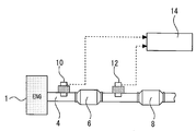
- Embodiment 1 of this invention It is a schematic diagram for demonstrating the whole structure of the system in Embodiment 1 of this invention. It is a figure for demonstrating the control in Embodiment 1 of this invention. It is a figure for demonstrating the routine of control which a control apparatus performs in Embodiment 1 of this invention. It is a figure for demonstrating the control in Embodiment 2 of this invention.
- FIG. FIG. 1 is a schematic diagram for explaining an overall configuration of a system according to Embodiment 1 of the present invention.
- the system of FIG. 1 is used by being mounted on a vehicle or the like.
- catalysts 6 and 8 are installed in the exhaust path 4 of the internal combustion engine 2.
- the catalyst 6 can purify exhaust gas by oxidizing carbon monoxide (CO) and hydrocarbons (HC) discharged from the internal combustion engine 2 and reducing nitrogen oxides (NOx).
- CO carbon monoxide
- HC hydrocarbons
- NOx nitrogen oxides
- An air-fuel ratio sensor 10 is installed upstream of the catalyst 6 in the exhaust path 4.
- An air-fuel ratio sensor 12 is installed downstream of the catalyst 6 in the exhaust path 4 and upstream of the catalyst 8. Both the air-fuel ratio sensors 10 and 12 are limit current type sensors, and emit an output corresponding to the air-fuel ratio of the exhaust gas to be detected.
- the air-fuel ratio sensor 10 on the upstream side of the catalyst 6 is also referred to as “Fr sensor 10”
- the air-fuel ratio sensor 12 on the downstream side is also referred to as “Rr sensor 12”.
- the control device 14 comprehensively controls the entire system of the internal combustion engine 2.
- Various actuators are connected to the output side of the control device 14, and various sensors such as the air-fuel ratio sensors 10 and 12 are connected to the input side.
- the control device 14 receives the sensor signal, detects the air-fuel ratio of the exhaust gas, the engine speed, and other various information necessary for the operation of the internal combustion engine 2, and operates each actuator according to a predetermined control program.
- Control executed by the control device 14 in this system includes control for correcting the output of the Rr sensor 12.
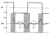
- FIG. 2 is a diagram for explaining the contents of the control in the first embodiment of the present invention.
- the straight line on the IN side represents the air-fuel ratio of the exhaust gas flowing into the catalyst 6
- the curve on the OUT side represents the Rr sensor 12 with respect to the exhaust gas flowing out of the catalyst 6. Represents the output.
- the control for correcting the Rr sensor 12 is performed by changing the air-fuel ratio of the exhaust gas flowing into the catalyst 6 to a rich air-fuel ratio that is rich with respect to the stoichiometric air-fuel ratio and a lean air-fuel ratio that is lean. This is done during active control to oscillate between. More specifically, in the example of FIG. 2, control for forcibly switching between the rich air-fuel ratio of 14.1 and the lean air-fuel ratio of 15.1 is executed.
- This active control is a control executed for other purposes such as determination of deterioration of the catalyst 6, for example, and is executed based on a control program stored in the control device 14.
- the air-fuel ratio of the IN-side exhaust gas flowing into the catalyst 6 is switched from the rich air-fuel ratio to the lean air-fuel ratio and maintained at the lean air-fuel ratio.
- the catalyst 6 oxidizes or reduces unburned components of the exhaust gas in the lean atmosphere and purifies it to an optimum state.
- a state where the exhaust gas is optimally purified in this way is referred to as an “optimal purification state”.
- exhaust gas purified to the vicinity of the theoretical air-fuel ratio is discharged downstream of the catalyst 6. Therefore, as shown in FIG. 2A, the Rr sensor 12 stably outputs a value corresponding to the theoretical air-fuel ratio.
- the catalyst 6 will occlude oxygen to the maximum extent and will no longer be able to occlude oxygen. In this state, the catalyst 6 cannot purify (reducing) the lean components (NOx, etc.), and exhaust gas in a lean atmosphere starts to be discharged downstream of the catalyst 6. Therefore, the output of the Rr sensor 12 becomes a value indicating a predetermined lean air-fuel ratio.
- the air-fuel ratio of the exhaust gas on the IN side of the catalyst 6 is switched to a rich air-fuel ratio. Rich exhaust gas flows into the catalyst 6, and gas equilibrium is advanced inside the catalyst 6, resulting in an “optimum purification state” in which the rich exhaust gas is purified to an optimum state. In this state, purified exhaust gas near the stoichiometric air-fuel ratio is discharged downstream of the catalyst 6. Accordingly, as shown in FIG. 2A, the output of the Rr sensor 12 is stabilized from a value indicating lean to a value corresponding to the stoichiometric air-fuel ratio.
- the catalyst 6 After that, if rich exhaust gas continues to flow into the catalyst 6, the catalyst 6 is in a state where it cannot purify the exhaust gas in the rich atmosphere that flows in. In this state, exhaust gas in a rich atmosphere flows out downstream of the catalyst 6. Therefore, the output of the Rr sensor 12 is a value indicating a rich atmosphere.
- the rich air-fuel ratio and lean air-fuel ratio as described above are repeatedly switched.
- the output of the Rr sensor 12 stably shows a value in the vicinity of the theoretical air-fuel ratio.
- the output of the Rr sensor 12 in the optimum purification state indicates a reference output (14.6) that is an output corresponding to the theoretical air-fuel ratio.
- the output value of the Rr sensor 12 may not be a value corresponding to the stoichiometric air-fuel ratio due to deterioration of the Fr sensor 10 and the Rr sensor 12 with time, initial variations, and the like.
- the deviation between the sensor output and the reference output in the optimum purification state is considered to be a deviation over the entire output of the Rr sensor 12.
- the output of the Rr sensor 12 in the optimal purification state during the active control is detected, the difference between the output detection value and the reference output (14.6) is obtained, and the average value of the differences Is calculated.
- the average value is used as an output correction coefficient for the Rr sensor 12.
- the rich air-fuel ratio is changed from 2 seconds after switching to the rich air-fuel ratio to 2 seconds before switching to the lean air-fuel ratio and from 2 seconds after switching to the lean air-fuel ratio.
- the period up to 2 seconds before switching to is set to the optimum state of the catalyst, and the output of the Rr sensor 12 during this period is detected and the correction coefficient is calculated.
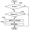
- FIG. 3 is a flowchart for illustrating a control routine executed by the control device in the first embodiment of the present invention.
- the precondition here is an operating condition in which active control is possible or whether active control is being executed, and is assumed to be predetermined and stored in the control device 14. If the establishment of the precondition is not recognized in step S102, the current process ends.
- the learning condition is, for example, whether or not the catalyst 6 is in an active state and the downstream side of the catalyst 6 is swung between a predetermined rich air-fuel ratio and a lean air-fuel ratio. It is assumed that it is stored in If the establishment of the learning condition is not recognized in step S104, the current process is temporarily terminated.
- step S106 the air-fuel ratio in the optimum purification state is detected (S106). Specifically, in the first embodiment, the air-fuel ratio is switched from the rich air-fuel ratio to the lean air-fuel ratio or from the lean air-fuel ratio to the rich air-fuel ratio during active control as the optimum purification state. A period excluding 2 seconds before and after is set. In step S106, the output of the Rr sensor 12 during this period is repeatedly detected every predetermined time until a predetermined number of samples is reached.
- a correction coefficient is calculated (S108).
- the difference between the output of the Rr sensor 12 detected in step S106 and the reference output (14.6) is obtained. Thereafter, an average value of this difference is calculated, and this average value is used as a correction coefficient. Thereafter, the current process is temporarily terminated.
- the calculated average value (correction coefficient) is used as a learning value for the optimum purification state of the Fr sensor 10 and the Rr sensor 12.
- the value (reference value) for the stoichiometric air-fuel ratio, which is the output reference is corrected as shown in the following equation (1).
- Reference value 14.6 + correction coefficient + other learning value (1)
- the outputs of the air-fuel ratio sensors 10 and 12 with respect to the optimum purification point of the catalyst 6 can be corrected, and control based on the optimum purification state can be executed.
- the present invention is not limited to this.
- the amount of intake air has a large effect on the catalyst purification performance.
- the engine speed may be divided into several regions, and the correction coefficient may be calculated in each region.
- the outputs of the air-fuel ratio sensors 10 and 12 can be corrected with higher accuracy.
- the second embodiment the same applies to the second embodiment.
- the correction of the air-fuel ratio sensors 10 and 12 of the first embodiment is made using timing during execution of active control that is other purpose control such as determination of deterioration of the catalyst 6.
- active control that is other purpose control such as determination of deterioration of the catalyst 6.
- the output of the Rr sensor 12 is detected in both cases of switching from the rich air-fuel ratio to the lean air-fuel ratio and switching from the lean air-fuel ratio to the rich air-fuel ratio, and the correction coefficient
- the catalyst 6 tends to change in the oxygen release rate depending on the deterioration state or poisoning state. The effect tends to appear when the air-fuel ratio is changed from rich to lean. Therefore, according to the present invention, in calculating the correction coefficient of the Rr sensor 12, the correction coefficient may be calculated using only the output when the lean air-fuel ratio is switched to the rich air-fuel ratio. Thereby, a more appropriate correction coefficient can be obtained. The same applies to the second embodiment.
- the upstream air-fuel ratio sensor 10 is not limited to this.
- the sensor on the upstream side of the catalyst 6 is used to control the air-fuel ratio upstream of the catalyst 6 to a predetermined rich air-fuel ratio and lean air-fuel ratio in active control. Therefore, in the present invention, instead of the air-fuel ratio sensor 10, another sensor that can detect the air-fuel ratio upstream of the catalyst 6 can be used.
- the present invention is not limited to the one in which an air-fuel ratio detection sensor is arranged upstream of the catalyst 6 in the exhaust path 4.
- the air-fuel ratio may be detected according to the output of the in-cylinder pressure sensor installed in the internal combustion engine 2 without installing the air-fuel ratio sensor 10. The same applies to the second embodiment.
- the calculation method of the correction coefficient for the air-fuel ratio sensors 10 and 12 is not limited to this, and any method may be used as long as it is detected by another method according to the difference from the reference output.
- the case where the output of the Rr sensor 12 is detected a plurality of times and this average value is used has been described, but the present invention is not limited to this, and the detection value of one time may be used as it is for the calculation of the correction coefficient. Good. The same applies to the second embodiment.
- the present invention is not limited to the case of obtaining a correction coefficient for correcting both the air-fuel ratio sensors 10 and 12, but may be a correction coefficient for correcting only the output of the air-fuel ratio sensor 12, for example. The same applies to the second embodiment.
- the air-fuel ratio is excluded from 2 seconds before and after switching from the rich air-fuel ratio to the lean air-fuel ratio or from the lean air-fuel ratio to the rich air-fuel ratio.
- the period corresponds to the “predetermined period during which the output of the air-fuel ratio sensor is balanced” in the present invention.
- FIG. The second embodiment has the same configuration as the system of FIG.
- the system of the second embodiment performs the same control as that of the system of the first embodiment except that a different period is defined as the predetermined period during which the output of the Rr sensor 12 is balanced. That is, also in the system of the second embodiment, the output of the Rr sensor 12 in the optimum purification state is detected, and the correction coefficient is calculated based on this output value. However, in the second embodiment, only the output when the differential value of the output change is equal to or less than a predetermined value is used, and the correction coefficient is calculated based on this output.
- FIG. 4 is a diagram showing the output of the Rr sensor 12 and its differential value.
- the upper curve is the output of the Rr sensor 12, and the lower curve shows a value obtained by differentiating the output change of the Rr sensor 12. Further, the hatched portion as shown in FIG. 4B is the optimum purification state.
- the differential value As shown in FIG. 4, when the air-fuel ratio of the exhaust gas downstream of the catalyst changes greatly from the rich air-fuel ratio to the lean air-fuel ratio or vice versa, it is confirmed that the differential value also increases. In the optimum purification state, the differential value also shows a stable value. However, the output of the Rr sensor 12 may include noise, and in this case, the differential value greatly changes even in the optimal purification state.
- the differential width for noise is obtained in advance by experiments or the like, and the allowable differential width (allowable range) is determined.
- the output of the Rr sensor 12 is used for calculating the correction coefficient.
- the calculation method and the correction method of the correction coefficient are the same as those in the first embodiment, and an average value of the difference between the output and the theoretical air-fuel ratio 14.6 is obtained and used as the correction coefficient.
- the noise included in the output of the Rr sensor 12 can be cut by using only the output during the period in which the differential value is within the allowable range as the output of the correction coefficient calculation. As a result, a more appropriate correction coefficient can be calculated, and the accuracy of air-fuel ratio control or the like can be improved.
- the period during which the differential value falls within the allowable range corresponds to the “predetermined period during which the output of the air-fuel ratio sensor is balanced” according to the present invention.
- the “predetermined period during which the output of the air-fuel ratio sensor is balanced” is not limited to this. For example, only the period in which the differential value falls within the allowable range for a certain period of time may be used as the “predetermined period” of the present invention, and only the output during this period may be used for calculating the correction coefficient.
Landscapes
- Engineering & Computer Science (AREA)
- Chemical & Material Sciences (AREA)
- Combustion & Propulsion (AREA)
- Mechanical Engineering (AREA)
- General Engineering & Computer Science (AREA)
- Analytical Chemistry (AREA)
- Health & Medical Sciences (AREA)
- Chemical Kinetics & Catalysis (AREA)
- Toxicology (AREA)
- Combined Controls Of Internal Combustion Engines (AREA)
- Electrical Control Of Air Or Fuel Supplied To Internal-Combustion Engine (AREA)
- Exhaust Gas After Treatment (AREA)
Abstract
Description
この発明は空燃比センサの補正装置に関する。更に具体的には、内燃機関の排気経路の触媒の下流に設置された空燃比センサの出力を補正する補正装置に関するものである。 The present invention relates to a correction device for an air-fuel ratio sensor. More specifically, the present invention relates to a correction device that corrects the output of an air-fuel ratio sensor installed downstream of a catalyst in an exhaust path of an internal combustion engine.
例えば、特許文献1には、内燃機関の触媒劣化検出装置が開示されている。この触媒劣化検出装置において、触媒の上流には空燃比センサが設置され、下流には起電力式の酸素センサが設置されている。この触媒劣化検出装置による触媒の劣化検出においては、触媒上流の空燃比が、所定のリッチ空燃比とリーン空燃比との間で振動するように強制的に制御される。そして、この制御において下流側の酸素センサがリーン出力からリッチ出力に変化するまでの時間値、あるいはリッチ出力からリーン出力を検出するまでの時間値が検出される。この触媒の劣化検出においては、このような時間値に基づいて触媒の酸素吸蔵量が算出され、更に、算出された酸素吸蔵量が所定値よりも大きいか否かに基づいて、触媒の劣化が判定される。 For example, Patent Document 1 discloses a catalyst deterioration detection device for an internal combustion engine. In this catalyst deterioration detection device, an air-fuel ratio sensor is installed upstream of the catalyst, and an electromotive force type oxygen sensor is installed downstream. In the catalyst deterioration detection by the catalyst deterioration detection device, the air-fuel ratio upstream of the catalyst is forcibly controlled so as to oscillate between a predetermined rich air-fuel ratio and lean air-fuel ratio. In this control, a time value until the downstream oxygen sensor changes from the lean output to the rich output or a time value until the lean output is detected from the rich output is detected. In this catalyst deterioration detection, the oxygen storage amount of the catalyst is calculated based on such a time value, and further, the catalyst deterioration is determined based on whether or not the calculated oxygen storage amount is larger than a predetermined value. Determined.
ところで、起電力式の酸素センサは、検出対象とするガスのガス量やガス濃度への依存が大きく、低濃度や低流量のガスに対しては出力が出にくくなる特徴がある。従って、今後、排ガス規制の厳格化等により、触媒下流に排出される排気ガスの濃度が更に低くなった場合、起電力式の酸素センサでは触媒下流の空燃比変化を正確に検出できなくなる事態が起こり得る。 By the way, the electromotive force type oxygen sensor has a characteristic that the dependence on the gas amount and the gas concentration of the gas to be detected is large, and it is difficult to output for a low concentration or low flow rate gas. Therefore, in the future, when exhaust gas concentration exhausted downstream due to stricter exhaust gas regulations, the electromotive force type oxygen sensor may not be able to accurately detect the air-fuel ratio change downstream of the catalyst. Can happen.
また、酸素センサは検出対象とするガスが低濃度になればなるほど、その出力応答性が遅れる傾向がある。従って、低濃度の排気ガス環境下では、リッチ空燃比とリーン空燃比との間での空燃比の変動に対し、即時に反応してその変化を検出することが困難となる。従って、上記従来技術のような触媒劣化検出など、下流側の酸素センサの出力変化に基づく制御の精度を高く維持することが難しくなると考えられる。 Also, the oxygen sensor tends to be delayed in its output response as the gas to be detected becomes lower in concentration. Therefore, in a low concentration exhaust gas environment, it is difficult to react immediately to the change in the air-fuel ratio between the rich air-fuel ratio and the lean air-fuel ratio and detect the change. Therefore, it is considered difficult to maintain high control accuracy based on changes in the output of the downstream oxygen sensor, such as detection of catalyst deterioration as in the above-described prior art.
これに対し、触媒下流側のセンサを例えば限界電流式の空燃比センサとすることが考えられる。限界電流式の空燃比センサであれば、極低濃度の排気ガスについても、ある程度正確にその空燃比を検出することができる。しかし空燃比センサについても、経時劣化や初期のばらつき等によりその出力にずれが生じる場合がある。このような場合には、空燃比センサの出力誤差により、触媒劣化判定等の制御の高い精度を維持することが難しい。 On the other hand, it is conceivable that the sensor on the downstream side of the catalyst is a limit current type air-fuel ratio sensor, for example. A limit current type air-fuel ratio sensor can detect the air-fuel ratio of a very low concentration exhaust gas with a certain degree of accuracy. However, the output of the air-fuel ratio sensor may also be shifted due to deterioration with time or initial variations. In such a case, it is difficult to maintain high accuracy of control such as catalyst deterioration determination due to an output error of the air-fuel ratio sensor.
以上より、この発明は上記課題を解決することを目的とし、触媒下流に空燃比センサを設置した場合に、その出力を適正に補正できるように改良した空燃比センサの補正装置を提供するものである。 In view of the above, the present invention aims to solve the above-described problems, and provides an improved air-fuel ratio sensor correction apparatus that can appropriately correct the output when an air-fuel ratio sensor is installed downstream of a catalyst. is there.
この発明は、上記の目的を達成するため、空燃比センサの補正装置であって、
内燃機関の排気経路に設置された触媒より上流側の排気ガスの空燃比を、理論空燃比に対してリッチであるリッチ空燃比とリーンであるリーン空燃比とを切り替えるように制御する空燃比制御手段と、
排気経路の触媒より下流の排気ガスの空燃比に応じた出力を発する空燃比センサと、
空燃比制御手段による空燃比制御中であって、触媒より下流に設置された空燃比センサの出力が平衡化する所定の期間における空燃比センサの出力と、理論空燃比に相当する基準出力との差異に応じて、空燃比センサの出力を補正する補正係数を算出する補正係数算出手段と、
を備える。
In order to achieve the above object, the present invention is an air-fuel ratio sensor correction apparatus comprising:
Air-fuel ratio control for controlling the air-fuel ratio of the exhaust gas upstream of the catalyst installed in the exhaust path of the internal combustion engine so as to switch between a rich air-fuel ratio that is rich with respect to the theoretical air-fuel ratio and a lean air-fuel ratio that is lean Means,
An air-fuel ratio sensor that emits an output corresponding to the air-fuel ratio of the exhaust gas downstream from the catalyst in the exhaust path;
The air-fuel ratio control is being performed by the air-fuel ratio control means, and the output of the air-fuel ratio sensor during a predetermined period in which the output of the air-fuel ratio sensor installed downstream from the catalyst is balanced and the reference output corresponding to the theoretical air-fuel ratio Correction coefficient calculating means for calculating a correction coefficient for correcting the output of the air-fuel ratio sensor according to the difference;
Is provided.
この発明において、空燃比センサの出力が平衡化する所定の期間は、空燃比制御手段により、触媒より上流側において空燃比がリッチ空燃比からリーン空燃比に切り替えられて第1の時間経過した後から、リーン空燃比から再びリッチ空燃比に切り替えられるときよりも第2の時間前までの期間、及び/又は、リーン空燃比からリッチ空燃比に切り替えられて第3の時間経過した後から、リッチ空燃比からリーン空燃比に切り替えられるときよりも第4の時間前までの期間とすることができる。ここで第1から第4の時間は、同一時間であってもよいし、それぞれ異なる時間であってもよい。 In the present invention, during a predetermined period in which the output of the air-fuel ratio sensor is balanced, after the first time has elapsed after the air-fuel ratio is switched from the rich air-fuel ratio to the lean air-fuel ratio upstream of the catalyst by the air-fuel ratio control means. Until the second time before switching from the lean air-fuel ratio to the rich air-fuel ratio again, and / or after the third time has elapsed since the lean air-fuel ratio was switched from the lean air-fuel ratio to the rich air-fuel ratio. The period before the fourth time can be set before switching from the air-fuel ratio to the lean air-fuel ratio. Here, the first to fourth times may be the same time or different times.
あるいは、所定の期間は、空燃比制御手段により、触媒より上流側において空燃比がリッチ空燃比からリーン空燃比に切り替えられて第1の時間経過した後から、リーン空燃比からリッチ空燃比に切り替えられるときよりも第2の時間前までの期間とすることもできる。ここで、第1、第2の時間は同一時間であってもよいし、互いに異なる時間であってもよい。 Alternatively, during a predetermined period, the air-fuel ratio is switched from the lean air-fuel ratio to the rich air-fuel ratio after the first time has elapsed after the air-fuel ratio is switched from the rich air-fuel ratio to the lean air-fuel ratio upstream of the catalyst by the air-fuel ratio control means. It is also possible to set the period up to the second time before the time when it is set. Here, the first time and the second time may be the same time or different times.
また、この発明の空燃比センサの補正装置は、空燃比センサの出力の変化の微分値を算出する微分値算出手段を、更に備えるものとすることができる。この場合、所定の期間は、微分値が所定の許容範囲内にある期間とすることができる。 In addition, the air-fuel ratio sensor correction apparatus of the present invention may further include a differential value calculating means for calculating a differential value of a change in the output of the air-fuel ratio sensor. In this case, the predetermined period can be a period in which the differential value is within a predetermined allowable range.
更に、微分値算出手段を用いるものについては、所定の期間は、微分値が許容範囲内にある期間が、一定時間の連続する期間とすることもできる。 Furthermore, with respect to those using the differential value calculation means, the predetermined period can be a period in which the differential value is within a permissible range and a continuous period.
また、所定の期間は、微分値が所定の許容範囲内にある期間とすると共に、更に、空燃比が空燃比センサをリーン空燃比からリッチ空燃比に切り替えられた後から、再び、リーン空燃比に切り替えられるまでの期間とすることもできる。 The predetermined period is a period in which the differential value is within a predetermined allowable range. Further, after the air-fuel ratio is switched from the lean air-fuel ratio to the rich air-fuel ratio, the lean air-fuel ratio is again set. It is also possible to set it as a period until it is switched to.
また、これらの所定の期間における空燃比センサの出力として、所定の期間の間に複数回検出された空燃比センサの出力の平均値を用いることとしてもよい。 Further, the average value of the output of the air-fuel ratio sensor detected a plurality of times during the predetermined period may be used as the output of the air-fuel ratio sensor in these predetermined periods.
この発明によれば、触媒上流の空燃比をリッチ空燃比又はリーン空燃比に切り替える制御を行った場合、触媒は、空燃比切り替え後のある期間中に最適な浄化状態となり、その状態で触媒下流側に排出される排気ガスは、理論空燃比近傍の排気ガスを最適な状態に還元したものとなる。このような状態となっている間、空燃比センサの出力は、理論空燃比に対応する出力に安定し、平衡化するものと考えられる。従って、空燃比センサの出力が平衡化する期間において、空燃比センサの出力と、理論空燃比に対応する基準出力とを比較することで、空燃比センサの基準出力に対するずれを求めることができる。更に、このずれに基づいて空燃比センサの出力補正係数を算出することで、空燃比センサの劣化等によるずれを補正することができる。 According to the present invention, when control is performed to switch the air-fuel ratio upstream of the catalyst to the rich air-fuel ratio or lean air-fuel ratio, the catalyst is in an optimal purification state during a certain period after the air-fuel ratio switch, and in that state, the catalyst downstream The exhaust gas discharged to the side is obtained by reducing the exhaust gas near the stoichiometric air-fuel ratio to an optimum state. While in such a state, the output of the air-fuel ratio sensor is considered to be stable and balanced to an output corresponding to the theoretical air-fuel ratio. Therefore, the deviation from the reference output of the air-fuel ratio sensor can be obtained by comparing the output of the air-fuel ratio sensor with the reference output corresponding to the theoretical air-fuel ratio during the period in which the output of the air-fuel ratio sensor is balanced. Further, by calculating the output correction coefficient of the air-fuel ratio sensor based on this deviation, the deviation due to deterioration of the air-fuel ratio sensor or the like can be corrected.
また、この発明において、空燃比を切り替える前後の所定時間を除いた期間を所定の期間とするものについては、触媒が最適な状態となり空燃比センサの出力が安定する期間の出力を、より確実に利用することができる。 Further, in the present invention, for a case where the period excluding the predetermined time before and after switching the air-fuel ratio is set as the predetermined period, the output during the period when the catalyst is in an optimal state and the output of the air-fuel ratio sensor is stabilized is more sure. Can be used.
また、この発明において、空燃比センサの出力変化の微分値が、所定の許容範囲内である場合の、空燃比センサの出力に基づいて空燃比センサの補正係数を求めるものについては、空燃比センサの出力に含まれるノイズ等をより確実に除去し、より適正な空燃比センサの出力補正係数を求めることができる。 Further, in the present invention, the air-fuel ratio sensor for obtaining the correction coefficient of the air-fuel ratio sensor based on the output of the air-fuel ratio sensor when the differential value of the output change of the air-fuel ratio sensor is within a predetermined allowable range. Noise and the like contained in the output of the air-fuel ratio can be more reliably removed, and a more appropriate output correction coefficient of the air-fuel ratio sensor can be obtained.
また、触媒の酸素放出速度は被毒状態や劣化状態による影響を受けやすく、その影響は、リッチ空燃比からリーン空燃比に切り替えられた場合に現れやすい。従って、この発明において、リーン空燃比からリッチ空燃比に切り替えられた場合の期間を所定の期間とし、その期間の出力を空燃比センサの補正に用いるものについては、更に高い精度で空燃比センサの補正を行うことができる。 Also, the oxygen release rate of the catalyst is easily affected by the poisoning state and the deterioration state, and the influence is likely to appear when the rich air-fuel ratio is switched to the lean air-fuel ratio. Accordingly, in the present invention, the period when the lean air-fuel ratio is switched from the lean air-fuel ratio to the predetermined air-fuel ratio is used as the predetermined period, and the output of the period is used for the correction of the air-fuel ratio sensor. Correction can be performed.
以下、図面を参照して本発明の実施の形態について説明する。なお、各図において、同一または相当する部分には同一符号を付してその説明を簡略化ないし省略する。 Hereinafter, embodiments of the present invention will be described with reference to the drawings. In the drawings, the same or corresponding parts are denoted by the same reference numerals, and the description thereof is simplified or omitted.
実施の形態1.
図1は、この発明の実施の形態1におけるシステムの全体構成について説明するための模式図である。図1のシステムは車両等に搭載されて用いられる。図1において、内燃機関2の排気経路4には、触媒6、8が設置されている。触媒6は内燃機関2から排出される一酸化炭素(CO)及び炭化水素(HC)を酸化すると共に、窒素酸化物(NOx)を還元することにより、排気ガスを浄化することができる。
Embodiment 1 FIG.
FIG. 1 is a schematic diagram for explaining an overall configuration of a system according to Embodiment 1 of the present invention. The system of FIG. 1 is used by being mounted on a vehicle or the like. In FIG. 1,
排気経路4の触媒6より上流側には空燃比センサ10が設置されている。排気経路4の触媒6より下流側かつ、触媒8より上流に、空燃比センサ12が設置されている。両空燃比センサ10、12は、共に限界電流式のセンサであり、検出対象となる排気ガスの空燃比に応じた出力を発する。なお、便宜的に、以下の実施の形態において、触媒6の上流側の空燃比センサ10を「Frセンサ10」、下流側の空燃比センサ12を「Rrセンサ12」とも称することとする。
An air-
図1のシステムは制御装置14を備えている。制御装置14は、内燃機関2のシステム全体を総合制御する。制御装置14の出力側には各種アクチュエータが接続され、入力側には空燃比センサ10、12等の各種センサが接続される。制御装置14は、センサ信号を受けて排気ガスの空燃比や機関回転数、その他内燃機関2の運転に必要な種々の情報を検出すると共に、所定の制御プログラムに従って各アクチュエータを操作する。なお、制御装置14に接続されるアクチュエータやセンサは多数存在するが、本明細書においてはその説明は省略する。このシステムにおいて制御装置14が実行する制御には、Rrセンサ12の出力の補正のための制御が含まれる。
The system shown in FIG. The
図2は、この発明の実施の形態1における制御の内容について説明するための図である。図2において、IN側(紙面上側)の直線は、触媒6に流入する排気ガスの空燃比を表し、OUT側(紙面下側)の曲線は、触媒6から流出する排気ガスに対するRrセンサ12の出力を表している。
FIG. 2 is a diagram for explaining the contents of the control in the first embodiment of the present invention. In FIG. 2, the straight line on the IN side (upper side of the paper) represents the air-fuel ratio of the exhaust gas flowing into the
図2に示されるように、Rrセンサ12の補正のための制御は、触媒6に流入させる排気ガスの空燃比を、理論空燃比に対してリッチであるリッチ空燃比とリーンであるリーン空燃比との間で振動させるアクティブ制御中に行われる。より具体的に、図2の例では、リッチ空燃比である14.1と、リーン空燃比である15.1とを強制的に切り替える制御が実行されている。なお、このアクティブ制御は、例えば触媒6の劣化判定等の他の目的のために実行される制御であり、制御装置14に記憶された制御プログラムに基づき実行される。
As shown in FIG. 2, the control for correcting the
このアクティブ制御においては、例えば、触媒6に流入するIN側の排気ガスの空燃比がリッチ空燃比から、リーン空燃比に切り替えられ、リーン空燃比に維持される。このとき、触媒6はリーン雰囲気の排気ガスの未燃成分を酸化又は還元し、最適な状態に浄化する。なお、このように排気ガスが最適に浄化されている状態を「最適浄化状態」と称することとする。この最適浄化状態において、触媒6の下流には理論空燃比近傍に浄化された排気ガスが排出される。従って、図2の(a)に示されるように、Rrセンサ12は、理論空燃比に対応する値を安定して出力する。
In this active control, for example, the air-fuel ratio of the IN-side exhaust gas flowing into the
しかし、触媒6にリーンな排気ガスが流入し続けると、触媒6が最大限に酸素を吸蔵し、もはや酸素を吸蔵できない状態となる。この状態となると、触媒6はリーン成分(NOx等)を浄化(還元)することができない状態となり、触媒6下流にはリーン雰囲気の排気ガスが排出され始める。従って、Rrセンサ12の出力は、所定のリーン空燃比を示す値となる。
However, if lean exhaust gas continues to flow into the
Rrセンサ12の出力がリーンを示す値となると、触媒6のIN側の排気ガスの空燃比がリッチ空燃比となるように切り替えられる。触媒6にはリッチな排気ガスが流入し、触媒6の内部ではガスの平衡化が進みリッチな排気ガスを最適な状態に浄化する「最適浄化状態」となる。この状態では触媒6の下流側には理論空燃比近傍の浄化された排気ガスが排出される。従って、図2(a)に示されるように、Rrセンサ12の出力は、リーンを示す値から理論空燃比に対応する値に安定する。
When the output of the
その後、触媒6にリッチな排気ガスが流入し続けると、触媒6は、流入するリッチ雰囲気の排気ガスを浄化することができない状態となる。この状態になると、触媒6下流には、リッチ雰囲気の排気ガスが流出する。従って、Rrセンサ12の出力はリッチ雰囲気を示す値となる。
After that, if rich exhaust gas continues to flow into the
その後、再びリーン雰囲気に切り替えられると、触媒6内部で再びガスの平衡化が進み、排気ガスが最適な状態に浄化される「触媒最適状態」となる。この状態ではRrセンサ12の出力は再び理論空燃比に対応する値に安定する。
After that, when the atmosphere is switched again to the lean atmosphere, the gas equilibration progresses again inside the
アクティブ制御中においては、以上のようなリッチ空燃比とリーン空燃比とを繰り返し切り替える。その切り替え後の一定期間、触媒が最適浄化状態となると、Rrセンサ12の出力も安定的に理論空燃比近傍の値を示す。ここで、理論的には、最適浄化状態におけるRrセンサ12の出力は理論空燃比に対応する出力である基準出力(14.6)を示すこととなる。
During active control, the rich air-fuel ratio and lean air-fuel ratio as described above are repeatedly switched. When the catalyst is in an optimal purification state for a certain period after the switching, the output of the
しかしながら、最適浄化状態にあっても、Frセンサ10やRrセンサ12の経時劣化、初期ばらつき等により、Rrセンサ12の出力値が理論空燃比に対応する値とならない場合がある。そして最適浄化状態におけるセンサ出力と基準出力とのずれは、Rrセンサ12の出力全体に渡るずれであると考えられる。
However, even in the optimum purification state, the output value of the
以上より、本実施の形態1では、上記アクティブ制御中の最適浄化状態におけるRrセンサ12の出力を検出し、出力検出値と基準出力(14.6)との差を求め、この差の平均値を算出する。そして、この平均値をRrセンサ12に対する出力補正係数として用いることとする。
As described above, in the first embodiment, the output of the
ただし、空燃比がリッチ空燃比からリーン空燃比あるいはリーン空燃比からリッチ空燃比に切り替えられた後、Rrセンサ12が安定的な出力を発するまでに、ある程度の時間を要する。従って、本実施の形態1では、リッチ空燃比に切り替えられて2秒後から、リーン空燃比に切り替えられる2秒前までの期間と、リーン空燃比に切り替えられて2秒後から、リッチ空燃比に切り替えられる2秒前までの期間を触媒最適状態とし、この間のRrセンサ12の出力を検出し補正係数を算出するものとする。
However, after the air-fuel ratio is switched from the rich air-fuel ratio to the lean air-fuel ratio or from the lean air-fuel ratio to the rich air-fuel ratio, it takes some time for the
図3は、この発明の実施の形態1において制御装置が実行する制御のルーチンについて説明するためのフローチャートである。図3の制御では、まず、前提条件が成立しているか否かが判別される(S102)。ここでの前提条件は、アクティブ制御が可能な運転条件か、あるいは、アクティブ制御実行中であるかなどであり、予め定められ、制御装置14に記憶されているものとする。ステップS102において前提条件の成立が認められない場合、今回の処理は終了する。
FIG. 3 is a flowchart for illustrating a control routine executed by the control device in the first embodiment of the present invention. In the control of FIG. 3, it is first determined whether or not the precondition is satisfied (S102). The precondition here is an operating condition in which active control is possible or whether active control is being executed, and is assumed to be predetermined and stored in the
一方、ステップS102において前提条件の成立が認められると、次に、学習条件が成立しているか否かが判別される(S104)。ここで学習条件は、例えば、触媒6が活性状態にあり、触媒6の下流側が所定のリッチ空燃比とリーン空燃比との間で振れているか否かなどであり、予め定められ、制御装置14に記憶されているものとする。ステップS104において、学習条件の成立が認められない場合、今回の処理は一旦終了する。
On the other hand, when the establishment of the precondition is recognized in step S102, it is next determined whether or not the learning condition is established (S104). Here, the learning condition is, for example, whether or not the
一方、ステップS104において学習条件の成立が認められると、最適浄化状態における空燃比が検出される(S106)。具体的には、本実施の形態1では、最適浄化状態として、アクティブ制御中であって、空燃比を、リッチ空燃比からリーン空燃比、あるいはリーン空燃比からリッチ空燃比とする空燃比の切り替えの前後2秒間を除いた期間が設定されている。ステップS106では、この期間におけるRrセンサ12の出力が、所定時間ごとに繰り返し所定サンプル数となるまで検出される。
On the other hand, when the learning condition is confirmed to be satisfied in step S104, the air-fuel ratio in the optimum purification state is detected (S106). Specifically, in the first embodiment, the air-fuel ratio is switched from the rich air-fuel ratio to the lean air-fuel ratio or from the lean air-fuel ratio to the rich air-fuel ratio during active control as the optimum purification state. A period excluding 2 seconds before and after is set. In step S106, the output of the
次に、補正係数が算出される(S108)。補正係数の算出においては、まず、ステップS106において検出されたRrセンサ12の出力と基準出力(14.6)との差が求められる。その後、この差の平均値が算出され、この平均値が補正係数とされる。その後、今回の処理は一旦終了する。
Next, a correction coefficient is calculated (S108). In calculating the correction coefficient, first, the difference between the output of the
なお、算出された平均値(補正係数)は、Frセンサ10、Rrセンサ12の最適浄化状態に対する学習値として用いられる。例えば、空燃比センサ10、12を用いた空燃比のフィードバック制御において、出力の基準となる理論空燃比に対する値(基準値)を、次式(1)のように補正する。
基準値=14.6+補正係数+その他学習値 ・・・・ (1)
The calculated average value (correction coefficient) is used as a learning value for the optimum purification state of the
Reference value = 14.6 + correction coefficient + other learning value (1)
このように、最適浄化状態におけるセンサ出力に基づく補正を行うことで、触媒6の劣化による浄化点のずれ、燃料の変化による理論空燃比のずれ、リッチガス増加等によるセンサの出力ずれ等の影響を受けることなく、触媒6の最適浄化点に対する空燃比センサ10、12の出力を補正することができ、最適浄化状態を基準とする制御を実行することができる。
Thus, by performing correction based on the sensor output in the optimal purification state, the influence of the deviation of the purification point due to the deterioration of the
なお、本実施の形態1においては運転領域に関わらず、アクティブ制御実行中に空燃比センサ10、12の補正係数を算出する制御を実行する場合について説明した。しかし、この発明はこれに限るものではない。吸入空気量は触媒浄化性能に対する影響が大きい。このような要素に対し、例えばエンジン回転数をいくつかの領域に分けて、各領域で、補正係数を算出するようにしてもよい。これにより、より高い精度で空燃比センサ10、12の出力を補正することが可能となる。これは、実施の形態2においても同様である。
In the first embodiment, the case where the control for calculating the correction coefficients of the air-
また、本実施の形態1においては、触媒6の劣化判定等、他の目的の制御であるアクティブ制御の実行中のタイミングを利用して、本実施の形態1の空燃比センサ10、12の補正係数を算出するための制御を実行する場合について説明した。これにより、効率的に補正係数の算出を行うことができる。しかし、この発明はこれに限るものではなく、空燃比センサ10、12の補正係数算出のために、アクティブ制御を別途実行することとしてもよい。これは実施の形態2においても同様である。
Further, in the first embodiment, the correction of the air-
また、実施の形態1においては、リッチ空燃比からリーン空燃比に切り替えた場合、リーン空燃比からリッチ空燃比に切り替えた場合のいずれの場合についても、Rrセンサ12の出力を検出し、補正係数算出に用いる場合について説明した。しかし、触媒6は、劣化状態や被毒状態によっては、酸素放出速度に変化が出やすい。そして、その影響は、リッチからリーンに空燃比を変化させた場合に現れやすい。従って、この発明は、Rrセンサ12の補正係数算出においては、リーン空燃比からリッチ空燃比へ切り替えた場合の出力のみを用いて補正係数を算出することとしてもよい。これにより、より適正な補正係数を得ることができる。これは実施の形態2においても同様である。
Further, in the first embodiment, the output of the
また、本実施の形態1では、触媒6の上流、下流にそれぞれ限界電流式の空燃比センサ10、12を配置する場合について説明した。しかし、この発明において上流側の空燃比センサ10はこれに限るものではない。触媒6の上流側のセンサは、アクティブ制御において触媒6上流の空燃比を、所定のリッチ空燃比、リーン空燃比に制御するために用いるものである。従って、本発明においては、空燃比センサ10に替えて、触媒6上流側の空燃比を検出できる他のセンサを用いることができる。また、この発明は、排気経路4の触媒6上流に空燃比検出用のセンサを配置するものに限られるものではない。例えば、空燃比センサ10を設置せず、内燃機関2に設置された筒内圧センサの出力に応じて空燃比を検出するものであってもよい。これは、実施の形態2においても同様である。
In the first embodiment, the case where limit current type air-
また、本実施の形態1においては、空燃比センサ10、12の補正係数として、Rrセンサ12の出力と基準出力との差の平均値を用いる場合について説明した。しかし、この発明において、空燃比センサ10、12に対する補正係数の算出方法はこれに限るものではなく、基準出力との差異に応じて他の手法により検出するものであればよい。また、Rrセンサ12の出力を複数回検出し、この平均値を用いる場合について説明したが、この発明はこれに限るものではなく、1回の検出値をそのまま補正係数の算出に用いることとしてもよい。これは実施の形態2においても同様である。
In the first embodiment, the case where the average value of the difference between the output of the
更に、本発明は、空燃比センサ10、12を共に補正する補正係数を求める場合にかぎられず、例えば空燃比センサ12の出力のみを補正する補正係数とするものであってもよい。これは実施の形態2においても同様である。
Furthermore, the present invention is not limited to the case of obtaining a correction coefficient for correcting both the air-
なお、例えば、実施の形態1において、アクティブ制御中であって、空燃比を、リッチ空燃比からリーン空燃比、あるいはリーン空燃比からリッチ空燃比とする空燃比の切り替えの前後2秒間を除いた期間が、この発明における「空燃比センサの出力が平衡化する所定の期間」に該当する。そして、本実施の形態1のステップS106及びS108が実行されることで、この発明の「補正係数算出手段」が実現する。 For example, in the first embodiment, during the active control, the air-fuel ratio is excluded from 2 seconds before and after switching from the rich air-fuel ratio to the lean air-fuel ratio or from the lean air-fuel ratio to the rich air-fuel ratio. The period corresponds to the “predetermined period during which the output of the air-fuel ratio sensor is balanced” in the present invention. Then, by executing steps S106 and S108 of the first embodiment, the “correction coefficient calculating means” of the present invention is realized.
実施の形態2.
実施の形態2は、図1のシステムと同様の構成を有している。また、実施の形態2のシステムは、Rrセンサ12の出力が平衡化する所定の期間として、異なる期間を規定する点を除いて、実施の形態1のシステムと同様の制御を行う。即ち、実施の形態2のシステムにおいても、最適浄化状態のRrセンサ12の出力を検出し、この出力値に基づいて補正係数を算出する。ただし、実施の形態2においては、その出力変化の微分値が所定値以下である場合の出力のみを用い、この出力に基づいて補正係数を算出する。
Embodiment 2. FIG.
The second embodiment has the same configuration as the system of FIG. The system of the second embodiment performs the same control as that of the system of the first embodiment except that a different period is defined as the predetermined period during which the output of the
図4は、Rrセンサ12の出力とその微分値を表す図である。また、図4において上部の曲線はRrセンサ12の出力であり、下部の曲線は、Rrセンサ12の出力変化を微分した値を示している。また図4におい(b)で示されるような斜線部分は最適浄化状態である。
FIG. 4 is a diagram showing the output of the
図4に示されるとおり、触媒下流の排気ガスの空燃比がリッチ空燃比からリーン空燃比、あるいはその逆に大きく変化するときに、その微分値も大きくなることが確認される。また、最適浄化状態では微分値も安定的な値を示す。しかしRrセンサ12の出力にはノイズが含まれる場合があり、この場合、最適浄化状態においても、微分値が大きく変化する。
As shown in FIG. 4, when the air-fuel ratio of the exhaust gas downstream of the catalyst changes greatly from the rich air-fuel ratio to the lean air-fuel ratio or vice versa, it is confirmed that the differential value also increases. In the optimum purification state, the differential value also shows a stable value. However, the output of the
従って、実施の形態2においては、ノイズ分の微分幅を事前に実験等により求め、許容される微分幅(許容範囲)を決定する。そして、微分値がこの許容範囲内に収まっている場合に、Rrセンサ12の出力を補正係数の算出に用いることとする。補正係数の算出方法や補正方法は、実施の形態1と同様であり、出力と理論空燃比14.6との差の平均値を求め、これを補正係数とする。
Therefore, in the second embodiment, the differential width for noise is obtained in advance by experiments or the like, and the allowable differential width (allowable range) is determined. When the differential value is within this allowable range, the output of the
以上のように、微分値が許容範囲内に収まる期間の出力のみを補正係数算出の出力として用いることで、Rrセンサ12の出力に含まれるノイズをカットすることができる。これにより、より適正な補正係数を算出することができ、空燃比制御等の精度を向上させることができる。
As described above, the noise included in the output of the
なお、本実施の形態2において、微分値が許容範囲に収まる期間が、本発明の「空燃比センサの出力が平衡化する所定の期間」に該当する。そして、本実施の形態2においては、この期間におけるセンサ出力補正係数の算出に用いる場合について説明した。しかし、この発明において、空燃比センサの出力が平衡化する所定の期間」はこれに限るものではない。例えば、微分値が許容範囲に収まる期間が、一定時間連続していう期間のみを、この発明の「所定の期間」とし、この期間における出力のみを補正係数の算出に用いるものとしてもよい。 In the second embodiment, the period during which the differential value falls within the allowable range corresponds to the “predetermined period during which the output of the air-fuel ratio sensor is balanced” according to the present invention. And in this Embodiment 2, the case where it used for calculation of the sensor output correction coefficient in this period was demonstrated. However, in the present invention, the “predetermined period during which the output of the air-fuel ratio sensor is balanced” is not limited to this. For example, only the period in which the differential value falls within the allowable range for a certain period of time may be used as the “predetermined period” of the present invention, and only the output during this period may be used for calculating the correction coefficient.
以上の実施の形態において各要素の個数、数量、量、範囲等の数に言及した場合、特に明示した場合や原理的に明らかにその数に特定される場合を除いて、その言及した数に、この発明が限定されるものではない。また、この実施の形態において説明する構造等は、特に明示した場合や明らかに原理的にそれに特定される場合を除いて、この発明に必ずしも必須のものではない。 In the above embodiment, when referring to the number of each element, quantity, quantity, range, etc., unless otherwise specified or clearly specified in principle, the number referred to However, the present invention is not limited. Further, the structure and the like described in this embodiment are not necessarily essential to the present invention unless otherwise specified or clearly specified in principle.
2 内燃機関
6、8 触媒
10 空燃比センサ(Frセンサ)
12 空燃比センサ(Rrセンサ)
14 制御装置
2
12 Air-fuel ratio sensor (Rr sensor)
14 Control device
Claims (7)
前記排気経路の前記触媒より下流の排気ガスの空燃比に応じた出力を発する空燃比センサと、
前記空燃比制御手段による空燃比制御中であって、前記触媒より下流に設置された空燃比センサの出力が平衡化する所定の期間における前記空燃比センサの出力と、理論空燃比に相当する基準出力との差異に応じて、前記空燃比センサの出力を補正する補正係数を算出する補正係数算出手段と、
を備えることを特徴とする空燃比センサの補正装置。 Air-fuel ratio control for controlling the air-fuel ratio of the exhaust gas upstream of the catalyst installed in the exhaust path of the internal combustion engine so as to switch between a rich air-fuel ratio that is rich with respect to the theoretical air-fuel ratio and a lean air-fuel ratio that is lean Means,
An air-fuel ratio sensor that emits an output corresponding to an air-fuel ratio of exhaust gas downstream from the catalyst in the exhaust path;
The air-fuel ratio control by the air-fuel ratio control means, and the output of the air-fuel ratio sensor in a predetermined period in which the output of the air-fuel ratio sensor installed downstream from the catalyst equilibrates, and a reference corresponding to the stoichiometric air-fuel ratio Correction coefficient calculating means for calculating a correction coefficient for correcting the output of the air-fuel ratio sensor according to the difference with the output;
A correction apparatus for an air-fuel ratio sensor comprising:
前記所定の期間は、前記微分値が所定の許容範囲内にある期間であることを特徴とする請求項1に記載の空燃比センサの補正装置。 A differential value calculating means for calculating a differential value of a change in the output of the air-fuel ratio sensor,
2. The correction device for an air-fuel ratio sensor according to claim 1, wherein the predetermined period is a period in which the differential value is within a predetermined allowable range.
Priority Applications (6)
| Application Number | Priority Date | Filing Date | Title |
|---|---|---|---|
| CN201180070990.0A CN103547784B (en) | 2011-05-19 | 2011-05-19 | Correction device for air-fuel ratio sensor |
| PCT/JP2011/061532 WO2012157111A1 (en) | 2011-05-19 | 2011-05-19 | Correction device for air/fuel ratio sensor |
| JP2013514938A JP5761340B2 (en) | 2011-05-19 | 2011-05-19 | Air-fuel ratio sensor correction device |
| EP11865664.4A EP2711528B1 (en) | 2011-05-19 | 2011-05-19 | Correction device for air/fuel ratio sensor |
| US14/114,770 US9347352B2 (en) | 2011-05-19 | 2011-05-19 | Correction device for air/fuel ratio sensor |
| US15/133,310 US10161343B2 (en) | 2011-05-19 | 2016-04-20 | Correction device for air/fuel ratio sensor |
Applications Claiming Priority (1)
| Application Number | Priority Date | Filing Date | Title |
|---|---|---|---|
| PCT/JP2011/061532 WO2012157111A1 (en) | 2011-05-19 | 2011-05-19 | Correction device for air/fuel ratio sensor |
Related Child Applications (2)
| Application Number | Title | Priority Date | Filing Date |
|---|---|---|---|
| US14/114,770 A-371-Of-International US9347352B2 (en) | 2011-05-19 | 2011-05-19 | Correction device for air/fuel ratio sensor |
| US15/133,310 Continuation US10161343B2 (en) | 2011-05-19 | 2016-04-20 | Correction device for air/fuel ratio sensor |
Publications (1)
| Publication Number | Publication Date |
|---|---|
| WO2012157111A1 true WO2012157111A1 (en) | 2012-11-22 |
Family
ID=47176473
Family Applications (1)
| Application Number | Title | Priority Date | Filing Date |
|---|---|---|---|
| PCT/JP2011/061532 Ceased WO2012157111A1 (en) | 2011-05-19 | 2011-05-19 | Correction device for air/fuel ratio sensor |
Country Status (5)
| Country | Link |
|---|---|
| US (2) | US9347352B2 (en) |
| EP (1) | EP2711528B1 (en) |
| JP (1) | JP5761340B2 (en) |
| CN (1) | CN103547784B (en) |
| WO (1) | WO2012157111A1 (en) |
Cited By (1)
| Publication number | Priority date | Publication date | Assignee | Title |
|---|---|---|---|---|
| US10267255B2 (en) | 2014-07-28 | 2019-04-23 | Toyota Jidosha Kabushiki Kaisha | Control system of internal combustion engine |
Families Citing this family (2)
| Publication number | Priority date | Publication date | Assignee | Title |
|---|---|---|---|---|
| WO2012157111A1 (en) * | 2011-05-19 | 2012-11-22 | トヨタ自動車株式会社 | Correction device for air/fuel ratio sensor |
| JP5668768B2 (en) * | 2013-02-25 | 2015-02-12 | トヨタ自動車株式会社 | Control device for internal combustion engine |
Citations (7)
| Publication number | Priority date | Publication date | Assignee | Title |
|---|---|---|---|---|
| JPH06280662A (en) | 1993-03-30 | 1994-10-04 | Mazda Motor Corp | Failure detection device for air-fuel ratio control device |
| JPH0979072A (en) * | 1995-09-11 | 1997-03-25 | Unisia Jecs Corp | Air-fuel ratio learning controller for internal combustion engine |
| JPH09125938A (en) * | 1995-11-07 | 1997-05-13 | Hitachi Ltd | Engine control device |
| JP2003097334A (en) | 2001-09-19 | 2003-04-03 | Toyota Motor Corp | Catalyst deterioration detection device for internal combustion engine |
| JP2005120870A (en) | 2003-10-15 | 2005-05-12 | Toyota Motor Corp | Air-fuel ratio control device for internal combustion engine |
| JP2006002579A (en) | 2004-06-15 | 2006-01-05 | Nissan Motor Co Ltd | Air-fuel ratio control device for internal combustion engine |
| JP2008075495A (en) * | 2006-09-20 | 2008-04-03 | Toyota Motor Corp | Air-fuel ratio control device for internal combustion engine |
Family Cites Families (12)
| Publication number | Priority date | Publication date | Assignee | Title |
|---|---|---|---|---|
| JP2917173B2 (en) * | 1990-09-04 | 1999-07-12 | 株式会社ユニシアジェックス | Air-fuel ratio control device for internal combustion engine |
| JP3651007B2 (en) | 1991-09-24 | 2005-05-25 | 株式会社デンソー | Air-fuel ratio control device for internal combustion engine |
| JPH10169500A (en) * | 1996-12-12 | 1998-06-23 | Unisia Jecs Corp | Air-fuel ratio sensor output correction device |
| DE60116158T2 (en) * | 2000-02-23 | 2006-06-29 | Nissan Motor Co. Ltd. | Air-fuel ratio control system |
| US7198952B2 (en) * | 2001-07-18 | 2007-04-03 | Toyota Jidosha Kabushiki Kaisha | Catalyst deterioration detecting apparatus and method |
| JP4345688B2 (en) * | 2005-02-24 | 2009-10-14 | 株式会社日立製作所 | Diagnostic device and control device for internal combustion engine |
| JP3941828B2 (en) * | 2005-09-15 | 2007-07-04 | トヨタ自動車株式会社 | Air-fuel ratio control device for internal combustion engine |
| JP4679335B2 (en) * | 2005-11-01 | 2011-04-27 | 日立オートモティブシステムズ株式会社 | Control device for internal combustion engine |
| DE102005059794B3 (en) | 2005-12-14 | 2007-03-29 | Siemens Ag | Exhaust gas probe calibrating method for use in internal combustion engine, involves detecting plateau phase of measuring signals of probe, after transfer of parameter of fat air-fuel ratio to parameter of lean air-fuel ratio |
| JP4380745B2 (en) * | 2007-07-20 | 2009-12-09 | トヨタ自動車株式会社 | Device for acquiring degree of deterioration of catalyst of internal combustion engine |
| JP5404262B2 (en) * | 2009-09-04 | 2014-01-29 | ダイハツ工業株式会社 | Air-fuel ratio control device |
| WO2012157111A1 (en) * | 2011-05-19 | 2012-11-22 | トヨタ自動車株式会社 | Correction device for air/fuel ratio sensor |
-
2011
- 2011-05-19 WO PCT/JP2011/061532 patent/WO2012157111A1/en not_active Ceased
- 2011-05-19 JP JP2013514938A patent/JP5761340B2/en not_active Expired - Fee Related
- 2011-05-19 CN CN201180070990.0A patent/CN103547784B/en not_active Expired - Fee Related
- 2011-05-19 EP EP11865664.4A patent/EP2711528B1/en not_active Not-in-force
- 2011-05-19 US US14/114,770 patent/US9347352B2/en not_active Expired - Fee Related
-
2016
- 2016-04-20 US US15/133,310 patent/US10161343B2/en active Active
Patent Citations (7)
| Publication number | Priority date | Publication date | Assignee | Title |
|---|---|---|---|---|
| JPH06280662A (en) | 1993-03-30 | 1994-10-04 | Mazda Motor Corp | Failure detection device for air-fuel ratio control device |
| JPH0979072A (en) * | 1995-09-11 | 1997-03-25 | Unisia Jecs Corp | Air-fuel ratio learning controller for internal combustion engine |
| JPH09125938A (en) * | 1995-11-07 | 1997-05-13 | Hitachi Ltd | Engine control device |
| JP2003097334A (en) | 2001-09-19 | 2003-04-03 | Toyota Motor Corp | Catalyst deterioration detection device for internal combustion engine |
| JP2005120870A (en) | 2003-10-15 | 2005-05-12 | Toyota Motor Corp | Air-fuel ratio control device for internal combustion engine |
| JP2006002579A (en) | 2004-06-15 | 2006-01-05 | Nissan Motor Co Ltd | Air-fuel ratio control device for internal combustion engine |
| JP2008075495A (en) * | 2006-09-20 | 2008-04-03 | Toyota Motor Corp | Air-fuel ratio control device for internal combustion engine |
Cited By (1)
| Publication number | Priority date | Publication date | Assignee | Title |
|---|---|---|---|---|
| US10267255B2 (en) | 2014-07-28 | 2019-04-23 | Toyota Jidosha Kabushiki Kaisha | Control system of internal combustion engine |
Also Published As
| Publication number | Publication date |
|---|---|
| JP5761340B2 (en) | 2015-08-12 |
| CN103547784A (en) | 2014-01-29 |
| US10161343B2 (en) | 2018-12-25 |
| US20140075924A1 (en) | 2014-03-20 |
| US20160230690A1 (en) | 2016-08-11 |
| US9347352B2 (en) | 2016-05-24 |
| EP2711528A1 (en) | 2014-03-26 |
| EP2711528B1 (en) | 2019-04-10 |
| JPWO2012157111A1 (en) | 2014-07-31 |
| EP2711528A4 (en) | 2016-01-06 |
| CN103547784B (en) | 2016-05-04 |
Similar Documents
| Publication | Publication Date | Title |
|---|---|---|
| JP6256240B2 (en) | Control device for internal combustion engine | |
| JP4941323B2 (en) | Control device for internal combustion engine | |
| JP6018543B2 (en) | Catalyst oxygen storage amount estimation method for internal combustion engine, air-fuel ratio control method for internal combustion engine, catalyst oxygen storage amount estimation device, air-fuel ratio control device for internal combustion engine, and motorcycle | |
| US20120317960A1 (en) | Catalyst degradation detection device | |
| EP2207953A2 (en) | Air-fuel ratio control apparatus and air-fuel ratio control method for internal combustion engine | |
| JP6056864B2 (en) | Control device for internal combustion engine | |
| JP5556962B2 (en) | Sensor characteristic correction device | |
| JP5761340B2 (en) | Air-fuel ratio sensor correction device | |
| JP5515967B2 (en) | Diagnostic equipment | |
| JP5783091B2 (en) | Output correction device for air-fuel ratio sensor | |
| JP2009002170A (en) | Air-fuel ratio control device for internal combustion engine | |
| JP2020026756A (en) | Engine control device and engine control method | |
| JP5761127B2 (en) | Catalyst deterioration diagnosis device | |
| JP2009092002A (en) | Air-fuel ratio control device for internal combustion engine | |
| JP5704038B2 (en) | Air-fuel ratio sensor correction device | |
| CN105822444A (en) | Supplementing and correcting device of air-fuel ratio sensor | |
| JP5835343B2 (en) | Air-fuel ratio detection device and air-fuel ratio detection method | |
| JP4345462B2 (en) | Air-fuel ratio control device for internal combustion engine | |
| JP2008128012A (en) | Air-fuel ratio detection device | |
| JP2007247412A (en) | Air-fuel ratio control device for internal combustion engine | |
| JP2006153026A (en) | Air-fuel ratio control device for internal combustion engine | |
| JP2008128070A (en) | Air-fuel ratio control device for internal combustion engine | |
| JP2009235997A (en) | Air-fuel ratio control method | |
| JP2008151058A (en) | Catalyst deterioration detection device for internal combustion engine | |
| JP2009235996A (en) | Air-fuel ratio control method |
Legal Events
| Date | Code | Title | Description |
|---|---|---|---|
| WWE | Wipo information: entry into national phase |
Ref document number: 201180070990.0 Country of ref document: CN |
|
| 121 | Ep: the epo has been informed by wipo that ep was designated in this application |
Ref document number: 11865664 Country of ref document: EP Kind code of ref document: A1 |
|
| ENP | Entry into the national phase |
Ref document number: 2013514938 Country of ref document: JP Kind code of ref document: A |
|
| WWE | Wipo information: entry into national phase |
Ref document number: 14114770 Country of ref document: US |
|
| WWE | Wipo information: entry into national phase |
Ref document number: 2011865664 Country of ref document: EP |
|
| NENP | Non-entry into the national phase |
Ref country code: DE |