WO2012157111A1 - Dispositif de correction pour détecteur de rapport air/carburant - Google Patents
Dispositif de correction pour détecteur de rapport air/carburant Download PDFInfo
- Publication number
- WO2012157111A1 WO2012157111A1 PCT/JP2011/061532 JP2011061532W WO2012157111A1 WO 2012157111 A1 WO2012157111 A1 WO 2012157111A1 JP 2011061532 W JP2011061532 W JP 2011061532W WO 2012157111 A1 WO2012157111 A1 WO 2012157111A1
- Authority
- WO
- WIPO (PCT)
- Prior art keywords
- fuel ratio
- air
- output
- sensor
- catalyst
- Prior art date
- Legal status (The legal status is an assumption and is not a legal conclusion. Google has not performed a legal analysis and makes no representation as to the accuracy of the status listed.)
- Ceased
Links
Images

Classifications
-
- F—MECHANICAL ENGINEERING; LIGHTING; HEATING; WEAPONS; BLASTING
- F02—COMBUSTION ENGINES; HOT-GAS OR COMBUSTION-PRODUCT ENGINE PLANTS
- F02D—CONTROLLING COMBUSTION ENGINES
- F02D41/00—Electrical control of supply of combustible mixture or its constituents
- F02D41/24—Electrical control of supply of combustible mixture or its constituents characterised by the use of digital means
- F02D41/2406—Electrical control of supply of combustible mixture or its constituents characterised by the use of digital means using essentially read only memories
- F02D41/2425—Particular ways of programming the data
- F02D41/2429—Methods of calibrating or learning
- F02D41/2451—Methods of calibrating or learning characterised by what is learned or calibrated
- F02D41/2474—Characteristics of sensors
-
- F—MECHANICAL ENGINEERING; LIGHTING; HEATING; WEAPONS; BLASTING
- F01—MACHINES OR ENGINES IN GENERAL; ENGINE PLANTS IN GENERAL; STEAM ENGINES
- F01N—GAS-FLOW SILENCERS OR EXHAUST APPARATUS FOR MACHINES OR ENGINES IN GENERAL; GAS-FLOW SILENCERS OR EXHAUST APPARATUS FOR INTERNAL-COMBUSTION ENGINES
- F01N3/00—Exhaust or silencing apparatus having means for purifying, rendering innocuous, or otherwise treating exhaust
- F01N3/08—Exhaust or silencing apparatus having means for purifying, rendering innocuous, or otherwise treating exhaust for rendering innocuous
- F01N3/10—Exhaust or silencing apparatus having means for purifying, rendering innocuous, or otherwise treating exhaust for rendering innocuous by thermal or catalytic conversion of noxious components of exhaust
- F01N3/18—Exhaust or silencing apparatus having means for purifying, rendering innocuous, or otherwise treating exhaust for rendering innocuous by thermal or catalytic conversion of noxious components of exhaust characterised by methods of operation; Control
-
- F—MECHANICAL ENGINEERING; LIGHTING; HEATING; WEAPONS; BLASTING
- F02—COMBUSTION ENGINES; HOT-GAS OR COMBUSTION-PRODUCT ENGINE PLANTS
- F02D—CONTROLLING COMBUSTION ENGINES
- F02D41/00—Electrical control of supply of combustible mixture or its constituents
- F02D41/02—Circuit arrangements for generating control signals
- F02D41/021—Introducing corrections for particular conditions exterior to the engine
- F02D41/0235—Introducing corrections for particular conditions exterior to the engine in relation with the state of the exhaust gas treating apparatus
-
- F—MECHANICAL ENGINEERING; LIGHTING; HEATING; WEAPONS; BLASTING
- F02—COMBUSTION ENGINES; HOT-GAS OR COMBUSTION-PRODUCT ENGINE PLANTS
- F02D—CONTROLLING COMBUSTION ENGINES
- F02D41/00—Electrical control of supply of combustible mixture or its constituents
- F02D41/02—Circuit arrangements for generating control signals
- F02D41/14—Introducing closed-loop corrections
- F02D41/1438—Introducing closed-loop corrections using means for determining characteristics of the combustion gases; Sensors therefor
- F02D41/1439—Introducing closed-loop corrections using means for determining characteristics of the combustion gases; Sensors therefor characterised by the position of the sensor
- F02D41/1441—Plural sensors
-
- F—MECHANICAL ENGINEERING; LIGHTING; HEATING; WEAPONS; BLASTING
- F02—COMBUSTION ENGINES; HOT-GAS OR COMBUSTION-PRODUCT ENGINE PLANTS
- F02D—CONTROLLING COMBUSTION ENGINES
- F02D41/00—Electrical control of supply of combustible mixture or its constituents
- F02D41/02—Circuit arrangements for generating control signals
- F02D41/14—Introducing closed-loop corrections
- F02D41/1438—Introducing closed-loop corrections using means for determining characteristics of the combustion gases; Sensors therefor
- F02D41/1444—Introducing closed-loop corrections using means for determining characteristics of the combustion gases; Sensors therefor characterised by the characteristics of the combustion gases
- F02D41/1454—Introducing closed-loop corrections using means for determining characteristics of the combustion gases; Sensors therefor characterised by the characteristics of the combustion gases the characteristics being an oxygen content or concentration or the air-fuel ratio
- F02D41/1456—Introducing closed-loop corrections using means for determining characteristics of the combustion gases; Sensors therefor characterised by the characteristics of the combustion gases the characteristics being an oxygen content or concentration or the air-fuel ratio with sensor output signal being linear or quasi-linear with the concentration of oxygen
-
- F—MECHANICAL ENGINEERING; LIGHTING; HEATING; WEAPONS; BLASTING
- F02—COMBUSTION ENGINES; HOT-GAS OR COMBUSTION-PRODUCT ENGINE PLANTS
- F02D—CONTROLLING COMBUSTION ENGINES
- F02D41/00—Electrical control of supply of combustible mixture or its constituents
- F02D41/24—Electrical control of supply of combustible mixture or its constituents characterised by the use of digital means
- F02D41/2406—Electrical control of supply of combustible mixture or its constituents characterised by the use of digital means using essentially read only memories
- F02D41/2425—Particular ways of programming the data
- F02D41/2429—Methods of calibrating or learning
- F02D41/2438—Active learning methods
-
- F—MECHANICAL ENGINEERING; LIGHTING; HEATING; WEAPONS; BLASTING
- F02—COMBUSTION ENGINES; HOT-GAS OR COMBUSTION-PRODUCT ENGINE PLANTS
- F02D—CONTROLLING COMBUSTION ENGINES
- F02D41/00—Electrical control of supply of combustible mixture or its constituents
- F02D41/24—Electrical control of supply of combustible mixture or its constituents characterised by the use of digital means
- F02D41/2406—Electrical control of supply of combustible mixture or its constituents characterised by the use of digital means using essentially read only memories
- F02D41/2425—Particular ways of programming the data
- F02D41/2429—Methods of calibrating or learning
- F02D41/2451—Methods of calibrating or learning characterised by what is learned or calibrated
- F02D41/2454—Learning of the air-fuel ratio control
-
- F—MECHANICAL ENGINEERING; LIGHTING; HEATING; WEAPONS; BLASTING
- F02—COMBUSTION ENGINES; HOT-GAS OR COMBUSTION-PRODUCT ENGINE PLANTS
- F02D—CONTROLLING COMBUSTION ENGINES
- F02D41/00—Electrical control of supply of combustible mixture or its constituents
- F02D41/24—Electrical control of supply of combustible mixture or its constituents characterised by the use of digital means
- F02D41/2406—Electrical control of supply of combustible mixture or its constituents characterised by the use of digital means using essentially read only memories
- F02D41/2425—Particular ways of programming the data
- F02D41/2429—Methods of calibrating or learning
- F02D41/2441—Methods of calibrating or learning characterised by the learning conditions
Definitions
- the present invention relates to a correction device for an air-fuel ratio sensor. More specifically, the present invention relates to a correction device that corrects the output of an air-fuel ratio sensor installed downstream of a catalyst in an exhaust path of an internal combustion engine.
- Patent Document 1 discloses a catalyst deterioration detection device for an internal combustion engine.
- an air-fuel ratio sensor is installed upstream of the catalyst, and an electromotive force type oxygen sensor is installed downstream.
- the air-fuel ratio upstream of the catalyst is forcibly controlled so as to oscillate between a predetermined rich air-fuel ratio and lean air-fuel ratio.
- a time value until the downstream oxygen sensor changes from the lean output to the rich output or a time value until the lean output is detected from the rich output is detected.
- the oxygen storage amount of the catalyst is calculated based on such a time value, and further, the catalyst deterioration is determined based on whether or not the calculated oxygen storage amount is larger than a predetermined value. Determined.
- the electromotive force type oxygen sensor has a characteristic that the dependence on the gas amount and the gas concentration of the gas to be detected is large, and it is difficult to output for a low concentration or low flow rate gas. Therefore, in the future, when exhaust gas concentration exhausted downstream due to stricter exhaust gas regulations, the electromotive force type oxygen sensor may not be able to accurately detect the air-fuel ratio change downstream of the catalyst. Can happen.
- the oxygen sensor tends to be delayed in its output response as the gas to be detected becomes lower in concentration. Therefore, in a low concentration exhaust gas environment, it is difficult to react immediately to the change in the air-fuel ratio between the rich air-fuel ratio and the lean air-fuel ratio and detect the change. Therefore, it is considered difficult to maintain high control accuracy based on changes in the output of the downstream oxygen sensor, such as detection of catalyst deterioration as in the above-described prior art.
- the senor on the downstream side of the catalyst is a limit current type air-fuel ratio sensor, for example.
- a limit current type air-fuel ratio sensor can detect the air-fuel ratio of a very low concentration exhaust gas with a certain degree of accuracy.
- the output of the air-fuel ratio sensor may also be shifted due to deterioration with time or initial variations. In such a case, it is difficult to maintain high accuracy of control such as catalyst deterioration determination due to an output error of the air-fuel ratio sensor.
- the present invention aims to solve the above-described problems, and provides an improved air-fuel ratio sensor correction apparatus that can appropriately correct the output when an air-fuel ratio sensor is installed downstream of a catalyst. is there.
- the present invention is an air-fuel ratio sensor correction apparatus comprising: Air-fuel ratio control for controlling the air-fuel ratio of the exhaust gas upstream of the catalyst installed in the exhaust path of the internal combustion engine so as to switch between a rich air-fuel ratio that is rich with respect to the theoretical air-fuel ratio and a lean air-fuel ratio that is lean Means, An air-fuel ratio sensor that emits an output corresponding to the air-fuel ratio of the exhaust gas downstream from the catalyst in the exhaust path;
- the air-fuel ratio control is being performed by the air-fuel ratio control means, and the output of the air-fuel ratio sensor during a predetermined period in which the output of the air-fuel ratio sensor installed downstream from the catalyst is balanced and the reference output corresponding to the theoretical air-fuel ratio
- Correction coefficient calculating means for calculating a correction coefficient for correcting the output of the air-fuel ratio sensor according to the difference; Is provided.
- the air-fuel ratio control means controls the air-fuel ratio control means.
- the period before the fourth time can be set before switching from the air-fuel ratio to the lean air-fuel ratio.
- the first to fourth times may be the same time or different times.
- the air-fuel ratio is switched from the lean air-fuel ratio to the rich air-fuel ratio after the first time has elapsed after the air-fuel ratio is switched from the rich air-fuel ratio to the lean air-fuel ratio upstream of the catalyst by the air-fuel ratio control means. It is also possible to set the period up to the second time before the time when it is set.
- the first time and the second time may be the same time or different times.
- the air-fuel ratio sensor correction apparatus of the present invention may further include a differential value calculating means for calculating a differential value of a change in the output of the air-fuel ratio sensor.
- the predetermined period can be a period in which the differential value is within a predetermined allowable range.
- the predetermined period can be a period in which the differential value is within a permissible range and a continuous period.
- the predetermined period is a period in which the differential value is within a predetermined allowable range. Further, after the air-fuel ratio is switched from the lean air-fuel ratio to the rich air-fuel ratio, the lean air-fuel ratio is again set. It is also possible to set it as a period until it is switched to.
- the average value of the output of the air-fuel ratio sensor detected a plurality of times during the predetermined period may be used as the output of the air-fuel ratio sensor in these predetermined periods.
- the catalyst when control is performed to switch the air-fuel ratio upstream of the catalyst to the rich air-fuel ratio or lean air-fuel ratio, the catalyst is in an optimal purification state during a certain period after the air-fuel ratio switch, and in that state, the catalyst downstream
- the exhaust gas discharged to the side is obtained by reducing the exhaust gas near the stoichiometric air-fuel ratio to an optimum state. While in such a state, the output of the air-fuel ratio sensor is considered to be stable and balanced to an output corresponding to the theoretical air-fuel ratio.
- the deviation from the reference output of the air-fuel ratio sensor can be obtained by comparing the output of the air-fuel ratio sensor with the reference output corresponding to the theoretical air-fuel ratio during the period in which the output of the air-fuel ratio sensor is balanced. Further, by calculating the output correction coefficient of the air-fuel ratio sensor based on this deviation, the deviation due to deterioration of the air-fuel ratio sensor or the like can be corrected.
- the output during the period when the catalyst is in an optimal state and the output of the air-fuel ratio sensor is stabilized is more sure. Can be used.
- the air-fuel ratio sensor for obtaining the correction coefficient of the air-fuel ratio sensor based on the output of the air-fuel ratio sensor when the differential value of the output change of the air-fuel ratio sensor is within a predetermined allowable range. Noise and the like contained in the output of the air-fuel ratio can be more reliably removed, and a more appropriate output correction coefficient of the air-fuel ratio sensor can be obtained.
- the oxygen release rate of the catalyst is easily affected by the poisoning state and the deterioration state, and the influence is likely to appear when the rich air-fuel ratio is switched to the lean air-fuel ratio. Accordingly, in the present invention, the period when the lean air-fuel ratio is switched from the lean air-fuel ratio to the predetermined air-fuel ratio is used as the predetermined period, and the output of the period is used for the correction of the air-fuel ratio sensor. Correction can be performed.
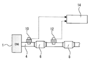
- Embodiment 1 of this invention It is a schematic diagram for demonstrating the whole structure of the system in Embodiment 1 of this invention. It is a figure for demonstrating the control in Embodiment 1 of this invention. It is a figure for demonstrating the routine of control which a control apparatus performs in Embodiment 1 of this invention. It is a figure for demonstrating the control in Embodiment 2 of this invention.
- FIG. FIG. 1 is a schematic diagram for explaining an overall configuration of a system according to Embodiment 1 of the present invention.
- the system of FIG. 1 is used by being mounted on a vehicle or the like.
- catalysts 6 and 8 are installed in the exhaust path 4 of the internal combustion engine 2.
- the catalyst 6 can purify exhaust gas by oxidizing carbon monoxide (CO) and hydrocarbons (HC) discharged from the internal combustion engine 2 and reducing nitrogen oxides (NOx).
- CO carbon monoxide
- HC hydrocarbons
- NOx nitrogen oxides
- An air-fuel ratio sensor 10 is installed upstream of the catalyst 6 in the exhaust path 4.
- An air-fuel ratio sensor 12 is installed downstream of the catalyst 6 in the exhaust path 4 and upstream of the catalyst 8. Both the air-fuel ratio sensors 10 and 12 are limit current type sensors, and emit an output corresponding to the air-fuel ratio of the exhaust gas to be detected.
- the air-fuel ratio sensor 10 on the upstream side of the catalyst 6 is also referred to as “Fr sensor 10”
- the air-fuel ratio sensor 12 on the downstream side is also referred to as “Rr sensor 12”.
- the control device 14 comprehensively controls the entire system of the internal combustion engine 2.
- Various actuators are connected to the output side of the control device 14, and various sensors such as the air-fuel ratio sensors 10 and 12 are connected to the input side.
- the control device 14 receives the sensor signal, detects the air-fuel ratio of the exhaust gas, the engine speed, and other various information necessary for the operation of the internal combustion engine 2, and operates each actuator according to a predetermined control program.
- Control executed by the control device 14 in this system includes control for correcting the output of the Rr sensor 12.
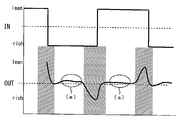
- FIG. 2 is a diagram for explaining the contents of the control in the first embodiment of the present invention.
- the straight line on the IN side represents the air-fuel ratio of the exhaust gas flowing into the catalyst 6
- the curve on the OUT side represents the Rr sensor 12 with respect to the exhaust gas flowing out of the catalyst 6. Represents the output.
- the control for correcting the Rr sensor 12 is performed by changing the air-fuel ratio of the exhaust gas flowing into the catalyst 6 to a rich air-fuel ratio that is rich with respect to the stoichiometric air-fuel ratio and a lean air-fuel ratio that is lean. This is done during active control to oscillate between. More specifically, in the example of FIG. 2, control for forcibly switching between the rich air-fuel ratio of 14.1 and the lean air-fuel ratio of 15.1 is executed.
- This active control is a control executed for other purposes such as determination of deterioration of the catalyst 6, for example, and is executed based on a control program stored in the control device 14.
- the air-fuel ratio of the IN-side exhaust gas flowing into the catalyst 6 is switched from the rich air-fuel ratio to the lean air-fuel ratio and maintained at the lean air-fuel ratio.
- the catalyst 6 oxidizes or reduces unburned components of the exhaust gas in the lean atmosphere and purifies it to an optimum state.
- a state where the exhaust gas is optimally purified in this way is referred to as an “optimal purification state”.
- exhaust gas purified to the vicinity of the theoretical air-fuel ratio is discharged downstream of the catalyst 6. Therefore, as shown in FIG. 2A, the Rr sensor 12 stably outputs a value corresponding to the theoretical air-fuel ratio.
- the catalyst 6 will occlude oxygen to the maximum extent and will no longer be able to occlude oxygen. In this state, the catalyst 6 cannot purify (reducing) the lean components (NOx, etc.), and exhaust gas in a lean atmosphere starts to be discharged downstream of the catalyst 6. Therefore, the output of the Rr sensor 12 becomes a value indicating a predetermined lean air-fuel ratio.
- the air-fuel ratio of the exhaust gas on the IN side of the catalyst 6 is switched to a rich air-fuel ratio. Rich exhaust gas flows into the catalyst 6, and gas equilibrium is advanced inside the catalyst 6, resulting in an “optimum purification state” in which the rich exhaust gas is purified to an optimum state. In this state, purified exhaust gas near the stoichiometric air-fuel ratio is discharged downstream of the catalyst 6. Accordingly, as shown in FIG. 2A, the output of the Rr sensor 12 is stabilized from a value indicating lean to a value corresponding to the stoichiometric air-fuel ratio.
- the catalyst 6 After that, if rich exhaust gas continues to flow into the catalyst 6, the catalyst 6 is in a state where it cannot purify the exhaust gas in the rich atmosphere that flows in. In this state, exhaust gas in a rich atmosphere flows out downstream of the catalyst 6. Therefore, the output of the Rr sensor 12 is a value indicating a rich atmosphere.
- the rich air-fuel ratio and lean air-fuel ratio as described above are repeatedly switched.
- the output of the Rr sensor 12 stably shows a value in the vicinity of the theoretical air-fuel ratio.
- the output of the Rr sensor 12 in the optimum purification state indicates a reference output (14.6) that is an output corresponding to the theoretical air-fuel ratio.
- the output value of the Rr sensor 12 may not be a value corresponding to the stoichiometric air-fuel ratio due to deterioration of the Fr sensor 10 and the Rr sensor 12 with time, initial variations, and the like.
- the deviation between the sensor output and the reference output in the optimum purification state is considered to be a deviation over the entire output of the Rr sensor 12.
- the output of the Rr sensor 12 in the optimal purification state during the active control is detected, the difference between the output detection value and the reference output (14.6) is obtained, and the average value of the differences Is calculated.
- the average value is used as an output correction coefficient for the Rr sensor 12.
- the rich air-fuel ratio is changed from 2 seconds after switching to the rich air-fuel ratio to 2 seconds before switching to the lean air-fuel ratio and from 2 seconds after switching to the lean air-fuel ratio.
- the period up to 2 seconds before switching to is set to the optimum state of the catalyst, and the output of the Rr sensor 12 during this period is detected and the correction coefficient is calculated.
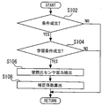
- FIG. 3 is a flowchart for illustrating a control routine executed by the control device in the first embodiment of the present invention.
- the precondition here is an operating condition in which active control is possible or whether active control is being executed, and is assumed to be predetermined and stored in the control device 14. If the establishment of the precondition is not recognized in step S102, the current process ends.
- the learning condition is, for example, whether or not the catalyst 6 is in an active state and the downstream side of the catalyst 6 is swung between a predetermined rich air-fuel ratio and a lean air-fuel ratio. It is assumed that it is stored in If the establishment of the learning condition is not recognized in step S104, the current process is temporarily terminated.
- step S106 the air-fuel ratio in the optimum purification state is detected (S106). Specifically, in the first embodiment, the air-fuel ratio is switched from the rich air-fuel ratio to the lean air-fuel ratio or from the lean air-fuel ratio to the rich air-fuel ratio during active control as the optimum purification state. A period excluding 2 seconds before and after is set. In step S106, the output of the Rr sensor 12 during this period is repeatedly detected every predetermined time until a predetermined number of samples is reached.
- a correction coefficient is calculated (S108).
- the difference between the output of the Rr sensor 12 detected in step S106 and the reference output (14.6) is obtained. Thereafter, an average value of this difference is calculated, and this average value is used as a correction coefficient. Thereafter, the current process is temporarily terminated.
- the calculated average value (correction coefficient) is used as a learning value for the optimum purification state of the Fr sensor 10 and the Rr sensor 12.
- the value (reference value) for the stoichiometric air-fuel ratio, which is the output reference is corrected as shown in the following equation (1).
- Reference value 14.6 + correction coefficient + other learning value (1)
- the outputs of the air-fuel ratio sensors 10 and 12 with respect to the optimum purification point of the catalyst 6 can be corrected, and control based on the optimum purification state can be executed.
- the present invention is not limited to this.
- the amount of intake air has a large effect on the catalyst purification performance.
- the engine speed may be divided into several regions, and the correction coefficient may be calculated in each region.
- the outputs of the air-fuel ratio sensors 10 and 12 can be corrected with higher accuracy.
- the second embodiment the same applies to the second embodiment.
- the correction of the air-fuel ratio sensors 10 and 12 of the first embodiment is made using timing during execution of active control that is other purpose control such as determination of deterioration of the catalyst 6.
- active control that is other purpose control such as determination of deterioration of the catalyst 6.
- the output of the Rr sensor 12 is detected in both cases of switching from the rich air-fuel ratio to the lean air-fuel ratio and switching from the lean air-fuel ratio to the rich air-fuel ratio, and the correction coefficient
- the catalyst 6 tends to change in the oxygen release rate depending on the deterioration state or poisoning state. The effect tends to appear when the air-fuel ratio is changed from rich to lean. Therefore, according to the present invention, in calculating the correction coefficient of the Rr sensor 12, the correction coefficient may be calculated using only the output when the lean air-fuel ratio is switched to the rich air-fuel ratio. Thereby, a more appropriate correction coefficient can be obtained. The same applies to the second embodiment.
- the upstream air-fuel ratio sensor 10 is not limited to this.
- the sensor on the upstream side of the catalyst 6 is used to control the air-fuel ratio upstream of the catalyst 6 to a predetermined rich air-fuel ratio and lean air-fuel ratio in active control. Therefore, in the present invention, instead of the air-fuel ratio sensor 10, another sensor that can detect the air-fuel ratio upstream of the catalyst 6 can be used.
- the present invention is not limited to the one in which an air-fuel ratio detection sensor is arranged upstream of the catalyst 6 in the exhaust path 4.
- the air-fuel ratio may be detected according to the output of the in-cylinder pressure sensor installed in the internal combustion engine 2 without installing the air-fuel ratio sensor 10. The same applies to the second embodiment.
- the calculation method of the correction coefficient for the air-fuel ratio sensors 10 and 12 is not limited to this, and any method may be used as long as it is detected by another method according to the difference from the reference output.
- the case where the output of the Rr sensor 12 is detected a plurality of times and this average value is used has been described, but the present invention is not limited to this, and the detection value of one time may be used as it is for the calculation of the correction coefficient. Good. The same applies to the second embodiment.
- the present invention is not limited to the case of obtaining a correction coefficient for correcting both the air-fuel ratio sensors 10 and 12, but may be a correction coefficient for correcting only the output of the air-fuel ratio sensor 12, for example. The same applies to the second embodiment.
- the air-fuel ratio is excluded from 2 seconds before and after switching from the rich air-fuel ratio to the lean air-fuel ratio or from the lean air-fuel ratio to the rich air-fuel ratio.
- the period corresponds to the “predetermined period during which the output of the air-fuel ratio sensor is balanced” in the present invention.
- FIG. The second embodiment has the same configuration as the system of FIG.
- the system of the second embodiment performs the same control as that of the system of the first embodiment except that a different period is defined as the predetermined period during which the output of the Rr sensor 12 is balanced. That is, also in the system of the second embodiment, the output of the Rr sensor 12 in the optimum purification state is detected, and the correction coefficient is calculated based on this output value. However, in the second embodiment, only the output when the differential value of the output change is equal to or less than a predetermined value is used, and the correction coefficient is calculated based on this output.
- FIG. 4 is a diagram showing the output of the Rr sensor 12 and its differential value.
- the upper curve is the output of the Rr sensor 12, and the lower curve shows a value obtained by differentiating the output change of the Rr sensor 12. Further, the hatched portion as shown in FIG. 4B is the optimum purification state.
- the differential value As shown in FIG. 4, when the air-fuel ratio of the exhaust gas downstream of the catalyst changes greatly from the rich air-fuel ratio to the lean air-fuel ratio or vice versa, it is confirmed that the differential value also increases. In the optimum purification state, the differential value also shows a stable value. However, the output of the Rr sensor 12 may include noise, and in this case, the differential value greatly changes even in the optimal purification state.
- the differential width for noise is obtained in advance by experiments or the like, and the allowable differential width (allowable range) is determined.
- the output of the Rr sensor 12 is used for calculating the correction coefficient.
- the calculation method and the correction method of the correction coefficient are the same as those in the first embodiment, and an average value of the difference between the output and the theoretical air-fuel ratio 14.6 is obtained and used as the correction coefficient.
- the noise included in the output of the Rr sensor 12 can be cut by using only the output during the period in which the differential value is within the allowable range as the output of the correction coefficient calculation. As a result, a more appropriate correction coefficient can be calculated, and the accuracy of air-fuel ratio control or the like can be improved.
- the period during which the differential value falls within the allowable range corresponds to the “predetermined period during which the output of the air-fuel ratio sensor is balanced” according to the present invention.
- the “predetermined period during which the output of the air-fuel ratio sensor is balanced” is not limited to this. For example, only the period in which the differential value falls within the allowable range for a certain period of time may be used as the “predetermined period” of the present invention, and only the output during this period may be used for calculating the correction coefficient.
Landscapes
- Engineering & Computer Science (AREA)
- Chemical & Material Sciences (AREA)
- Combustion & Propulsion (AREA)
- Mechanical Engineering (AREA)
- General Engineering & Computer Science (AREA)
- Analytical Chemistry (AREA)
- Health & Medical Sciences (AREA)
- Chemical Kinetics & Catalysis (AREA)
- Toxicology (AREA)
- Combined Controls Of Internal Combustion Engines (AREA)
- Electrical Control Of Air Or Fuel Supplied To Internal-Combustion Engine (AREA)
- Exhaust Gas After Treatment (AREA)
Abstract
Priority Applications (6)
| Application Number | Priority Date | Filing Date | Title |
|---|---|---|---|
| JP2013514938A JP5761340B2 (ja) | 2011-05-19 | 2011-05-19 | 空燃比センサの補正装置 |
| US14/114,770 US9347352B2 (en) | 2011-05-19 | 2011-05-19 | Correction device for air/fuel ratio sensor |
| EP11865664.4A EP2711528B1 (fr) | 2011-05-19 | 2011-05-19 | Dispositif de correction pour détecteur de rapport air/carburant |
| CN201180070990.0A CN103547784B (zh) | 2011-05-19 | 2011-05-19 | 空燃比传感器的补正装置 |
| PCT/JP2011/061532 WO2012157111A1 (fr) | 2011-05-19 | 2011-05-19 | Dispositif de correction pour détecteur de rapport air/carburant |
| US15/133,310 US10161343B2 (en) | 2011-05-19 | 2016-04-20 | Correction device for air/fuel ratio sensor |
Applications Claiming Priority (1)
| Application Number | Priority Date | Filing Date | Title |
|---|---|---|---|
| PCT/JP2011/061532 WO2012157111A1 (fr) | 2011-05-19 | 2011-05-19 | Dispositif de correction pour détecteur de rapport air/carburant |
Related Child Applications (2)
| Application Number | Title | Priority Date | Filing Date |
|---|---|---|---|
| US14/114,770 A-371-Of-International US9347352B2 (en) | 2011-05-19 | 2011-05-19 | Correction device for air/fuel ratio sensor |
| US15/133,310 Continuation US10161343B2 (en) | 2011-05-19 | 2016-04-20 | Correction device for air/fuel ratio sensor |
Publications (1)
| Publication Number | Publication Date |
|---|---|
| WO2012157111A1 true WO2012157111A1 (fr) | 2012-11-22 |
Family
ID=47176473
Family Applications (1)
| Application Number | Title | Priority Date | Filing Date |
|---|---|---|---|
| PCT/JP2011/061532 Ceased WO2012157111A1 (fr) | 2011-05-19 | 2011-05-19 | Dispositif de correction pour détecteur de rapport air/carburant |
Country Status (5)
| Country | Link |
|---|---|
| US (2) | US9347352B2 (fr) |
| EP (1) | EP2711528B1 (fr) |
| JP (1) | JP5761340B2 (fr) |
| CN (1) | CN103547784B (fr) |
| WO (1) | WO2012157111A1 (fr) |
Cited By (1)
| Publication number | Priority date | Publication date | Assignee | Title |
|---|---|---|---|---|
| US10267255B2 (en) | 2014-07-28 | 2019-04-23 | Toyota Jidosha Kabushiki Kaisha | Control system of internal combustion engine |
Families Citing this family (2)
| Publication number | Priority date | Publication date | Assignee | Title |
|---|---|---|---|---|
| WO2012157111A1 (fr) * | 2011-05-19 | 2012-11-22 | トヨタ自動車株式会社 | Dispositif de correction pour détecteur de rapport air/carburant |
| JP5668768B2 (ja) * | 2013-02-25 | 2015-02-12 | トヨタ自動車株式会社 | 内燃機関の制御装置 |
Citations (7)
| Publication number | Priority date | Publication date | Assignee | Title |
|---|---|---|---|---|
| JPH06280662A (ja) | 1993-03-30 | 1994-10-04 | Mazda Motor Corp | 空燃比制御装置の故障検出装置 |
| JPH0979072A (ja) * | 1995-09-11 | 1997-03-25 | Unisia Jecs Corp | 内燃機関の空燃比学習制御装置 |
| JPH09125938A (ja) * | 1995-11-07 | 1997-05-13 | Hitachi Ltd | エンジン制御装置 |
| JP2003097334A (ja) | 2001-09-19 | 2003-04-03 | Toyota Motor Corp | 内燃機関の触媒劣化検出装置 |
| JP2005120870A (ja) | 2003-10-15 | 2005-05-12 | Toyota Motor Corp | 内燃機関の空燃比制御装置 |
| JP2006002579A (ja) | 2004-06-15 | 2006-01-05 | Nissan Motor Co Ltd | 内燃機関の空燃比制御装置 |
| JP2008075495A (ja) * | 2006-09-20 | 2008-04-03 | Toyota Motor Corp | 内燃機関の空燃比制御装置 |
Family Cites Families (12)
| Publication number | Priority date | Publication date | Assignee | Title |
|---|---|---|---|---|
| JP2917173B2 (ja) * | 1990-09-04 | 1999-07-12 | 株式会社ユニシアジェックス | 内燃機関の空燃比制御装置 |
| JP3651007B2 (ja) * | 1991-09-24 | 2005-05-25 | 株式会社デンソー | 内燃機関の空燃比制御装置 |
| JPH10169500A (ja) * | 1996-12-12 | 1998-06-23 | Unisia Jecs Corp | 空燃比センサの出力補正装置 |
| EP1128045B1 (fr) * | 2000-02-23 | 2005-12-28 | Nissan Motor Co., Ltd. | Système de commande de rapport air-carburant |
| US7198952B2 (en) | 2001-07-18 | 2007-04-03 | Toyota Jidosha Kabushiki Kaisha | Catalyst deterioration detecting apparatus and method |
| JP4345688B2 (ja) * | 2005-02-24 | 2009-10-14 | 株式会社日立製作所 | 内燃機関の診断装置および制御装置 |
| JP3941828B2 (ja) * | 2005-09-15 | 2007-07-04 | トヨタ自動車株式会社 | 内燃機関の空燃比制御装置 |
| JP4679335B2 (ja) * | 2005-11-01 | 2011-04-27 | 日立オートモティブシステムズ株式会社 | 内燃機関の制御装置 |
| DE102005059794B3 (de) * | 2005-12-14 | 2007-03-29 | Siemens Ag | Verfahren und Vorrichtung zum Kalibrieren einer Abgassonde und Verfahren und Vorrichtung zum Betreiben einer Brennkraftmaschine |
| JP4380745B2 (ja) * | 2007-07-20 | 2009-12-09 | トヨタ自動車株式会社 | 内燃機関の触媒の劣化度合い取得装置 |
| JP5404262B2 (ja) * | 2009-09-04 | 2014-01-29 | ダイハツ工業株式会社 | 空燃比制御装置 |
| WO2012157111A1 (fr) * | 2011-05-19 | 2012-11-22 | トヨタ自動車株式会社 | Dispositif de correction pour détecteur de rapport air/carburant |
-
2011
- 2011-05-19 WO PCT/JP2011/061532 patent/WO2012157111A1/fr not_active Ceased
- 2011-05-19 JP JP2013514938A patent/JP5761340B2/ja not_active Expired - Fee Related
- 2011-05-19 US US14/114,770 patent/US9347352B2/en not_active Expired - Fee Related
- 2011-05-19 CN CN201180070990.0A patent/CN103547784B/zh not_active Expired - Fee Related
- 2011-05-19 EP EP11865664.4A patent/EP2711528B1/fr not_active Not-in-force
-
2016
- 2016-04-20 US US15/133,310 patent/US10161343B2/en active Active
Patent Citations (7)
| Publication number | Priority date | Publication date | Assignee | Title |
|---|---|---|---|---|
| JPH06280662A (ja) | 1993-03-30 | 1994-10-04 | Mazda Motor Corp | 空燃比制御装置の故障検出装置 |
| JPH0979072A (ja) * | 1995-09-11 | 1997-03-25 | Unisia Jecs Corp | 内燃機関の空燃比学習制御装置 |
| JPH09125938A (ja) * | 1995-11-07 | 1997-05-13 | Hitachi Ltd | エンジン制御装置 |
| JP2003097334A (ja) | 2001-09-19 | 2003-04-03 | Toyota Motor Corp | 内燃機関の触媒劣化検出装置 |
| JP2005120870A (ja) | 2003-10-15 | 2005-05-12 | Toyota Motor Corp | 内燃機関の空燃比制御装置 |
| JP2006002579A (ja) | 2004-06-15 | 2006-01-05 | Nissan Motor Co Ltd | 内燃機関の空燃比制御装置 |
| JP2008075495A (ja) * | 2006-09-20 | 2008-04-03 | Toyota Motor Corp | 内燃機関の空燃比制御装置 |
Cited By (1)
| Publication number | Priority date | Publication date | Assignee | Title |
|---|---|---|---|---|
| US10267255B2 (en) | 2014-07-28 | 2019-04-23 | Toyota Jidosha Kabushiki Kaisha | Control system of internal combustion engine |
Also Published As
| Publication number | Publication date |
|---|---|
| EP2711528A4 (fr) | 2016-01-06 |
| US20160230690A1 (en) | 2016-08-11 |
| EP2711528B1 (fr) | 2019-04-10 |
| JPWO2012157111A1 (ja) | 2014-07-31 |
| CN103547784A (zh) | 2014-01-29 |
| US10161343B2 (en) | 2018-12-25 |
| CN103547784B (zh) | 2016-05-04 |
| US20140075924A1 (en) | 2014-03-20 |
| JP5761340B2 (ja) | 2015-08-12 |
| US9347352B2 (en) | 2016-05-24 |
| EP2711528A1 (fr) | 2014-03-26 |
Similar Documents
| Publication | Publication Date | Title |
|---|---|---|
| JP6256240B2 (ja) | 内燃機関の制御装置 | |
| JP4941323B2 (ja) | 内燃機関の制御装置 | |
| JP6018543B2 (ja) | 内燃機関における触媒の酸素吸蔵量推定方法、内燃機関の空燃比制御方法、触媒の酸素吸蔵量推定装置、内燃機関の空燃比制御装置及び自動二輪車 | |
| EP2207953A2 (fr) | Appareil de régulation de rapport air-carburant et procédé de régulation de rapport air-carburant pour moteur à combustion interne | |
| JP6056864B2 (ja) | 内燃機関の制御装置 | |
| JP5556962B2 (ja) | センサの特性補正装置 | |
| JP5761340B2 (ja) | 空燃比センサの補正装置 | |
| JP5515967B2 (ja) | 診断装置 | |
| JP5783091B2 (ja) | 空燃比センサの出力補正装置 | |
| JP2009002170A (ja) | 内燃機関の空燃比制御装置 | |
| JP2020026756A (ja) | エンジン制御装置及エンジン制御方法 | |
| JP5761127B2 (ja) | 触媒劣化診断装置 | |
| JP2009092002A (ja) | 内燃機関の空燃比制御装置 | |
| JP5704038B2 (ja) | 空燃比センサの補正装置 | |
| CN105822444A (zh) | 空燃比传感器的补正装置 | |
| JP5835343B2 (ja) | 空燃比検出装置及び空燃比検出方法 | |
| JP4345462B2 (ja) | 内燃機関の空燃比制御装置 | |
| JP2005139921A (ja) | 内燃機関の排気浄化システム | |
| JP2007032438A (ja) | 内燃機関の空燃比制御装置 | |
| JP2008128012A (ja) | 空燃比検出装置 | |
| JP2007247412A (ja) | 内燃機関の空燃比制御装置 | |
| JP2009127561A (ja) | 内燃機関の空燃比制御装置 | |
| JP2006153026A (ja) | 内燃機関の空燃比制御装置 | |
| JP2008128070A (ja) | 内燃機関の空燃比制御装置 | |
| JP2009235997A (ja) | 空燃比制御方法 |
Legal Events
| Date | Code | Title | Description |
|---|---|---|---|
| WWE | Wipo information: entry into national phase |
Ref document number: 201180070990.0 Country of ref document: CN |
|
| 121 | Ep: the epo has been informed by wipo that ep was designated in this application |
Ref document number: 11865664 Country of ref document: EP Kind code of ref document: A1 |
|
| ENP | Entry into the national phase |
Ref document number: 2013514938 Country of ref document: JP Kind code of ref document: A |
|
| WWE | Wipo information: entry into national phase |
Ref document number: 14114770 Country of ref document: US |
|
| WWE | Wipo information: entry into national phase |
Ref document number: 2011865664 Country of ref document: EP |
|
| NENP | Non-entry into the national phase |
Ref country code: DE |