WO2012157190A1 - Système optique pour appareil de mesure de la caractéristique de réflexion, et appareil de mesure de la caractéristique de réflexion - Google Patents
Système optique pour appareil de mesure de la caractéristique de réflexion, et appareil de mesure de la caractéristique de réflexion Download PDFInfo
- Publication number
- WO2012157190A1 WO2012157190A1 PCT/JP2012/002716 JP2012002716W WO2012157190A1 WO 2012157190 A1 WO2012157190 A1 WO 2012157190A1 JP 2012002716 W JP2012002716 W JP 2012002716W WO 2012157190 A1 WO2012157190 A1 WO 2012157190A1
- Authority
- WO
- WIPO (PCT)
- Prior art keywords
- light
- reflection characteristic
- optical system
- characteristic measuring
- sample
- Prior art date
- Legal status (The legal status is an assumption and is not a legal conclusion. Google has not performed a legal analysis and makes no representation as to the accuracy of the status listed.)
- Ceased
Links
Images


Classifications
-
- G—PHYSICS
- G01—MEASURING; TESTING
- G01N—INVESTIGATING OR ANALYSING MATERIALS BY DETERMINING THEIR CHEMICAL OR PHYSICAL PROPERTIES
- G01N21/00—Investigating or analysing materials by the use of optical means, i.e. using sub-millimetre waves, infrared, visible or ultraviolet light
- G01N21/17—Systems in which incident light is modified in accordance with the properties of the material investigated
- G01N21/47—Scattering, i.e. diffuse reflection
- G01N21/4738—Diffuse reflection, e.g. also for testing fluids, fibrous materials
-
- G—PHYSICS
- G01—MEASURING; TESTING
- G01N—INVESTIGATING OR ANALYSING MATERIALS BY DETERMINING THEIR CHEMICAL OR PHYSICAL PROPERTIES
- G01N21/00—Investigating or analysing materials by the use of optical means, i.e. using sub-millimetre waves, infrared, visible or ultraviolet light
- G01N21/17—Systems in which incident light is modified in accordance with the properties of the material investigated
- G01N21/25—Colour; Spectral properties, i.e. comparison of effect of material on the light at two or more different wavelengths or wavelength bands
- G01N21/27—Colour; Spectral properties, i.e. comparison of effect of material on the light at two or more different wavelengths or wavelength bands using photo-electric detection ; circuits for computing concentration
- G01N21/274—Calibration, base line adjustment, drift correction
Definitions
- a standard plate is provided in the reflection characteristic measuring apparatus, the standard plate is moved to a measurement opening facing a sample, and the standard plate is measured to determine the amount of change in the optical characteristics of illumination light.
- the reflection surface of the standard plate is closer to the illumination optical system and the light receiving optical system than the measurement surface of the sample, the irradiation position where the illumination light is irradiated onto the sample and the irradiation position where the standard plate is irradiated are shifted. Therefore, the calibration accuracy is reduced accordingly.
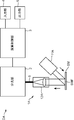
- the illumination light-receiving optical system 1A transmits illumination light to the sample measurement surface of the sample SM with a predetermined geometry set in advance with respect to a predetermined measurement plane set in advance as a position (place) for measuring the sample SM to be measured.
- This is an optical system that irradiates the SMF and receives the reflected light.
- the geometry is an incident direction of illumination light and an observation direction of reflected light with respect to the measurement plane.
- the illumination light receiving optical system 1A includes an illumination system 11A and a light receiving optical system 12A.
- the reflection member 13A and the standard member 14A are further provided for calibration in the reflection characteristic measuring apparatus DA. I have. In FIG. 1, the reflecting member 13A and the standard member 14A are not shown.
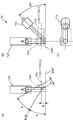
- the reflection member 13A is configured to be insertable / removable at a calibration position arranged when the reflection characteristic measuring apparatus DA is calibrated. That is, the reflection member 13A can be inserted and arranged at the calibration position when calibration is performed, and can be removed from the calibration position when measurement is performed. More specifically, the reflecting member 13A measures the calibration position arranged when the reflection characteristic measuring apparatus DA is calibrated, and the reflection characteristic of the sample measurement surface SMF in the sample SM that is retracted from the calibration position. The standby position arranged in this case can be switched by, for example, a mechanism described later.
- the calibration position of the reflecting member 13A is a predetermined position on the first optical path of the illumination light irradiated on the sample measurement surface SMF of the sample SM.
- the first and second guide rods 26-1 and 26-2 are protruded with a space therebetween.
- the reflecting member 13A (the first reflecting member 13A-1 and the second reflecting member 13A-2) and the standard member are guided by the pair of first and second guide rods 26-1 and 26-2.
- An attachment member 25 attached to one side of 14A is movably disposed on the pair of first and second guide rods 26-1 and 26-2.
- a long rod-like arm member 24 is connected to the other end of the mounting member 25 at one end thereof.
- a rotation shaft of the solenoid motor 23 is fixed at the approximate center of the arm member 24.
- the solenoid motor 23 is fixed to the fixed body 21 via a substantially L-shaped fixed connection member 22 in a side view.
- the arithmetic control unit 3 is, for example, a microcomputer including a CPU (Central Processing Unit), storage elements such as ROM and RAM, and peripheral circuits thereof.
- CPU Central Processing Unit
- the input unit 4 is a device for inputting commands (commands), data, and the like from the outside, such as a touch panel and a keyboard.
- the output unit 5 is a device for outputting commands and data input from the input unit 4 and the calculation result of the calculation control unit 3, and is an LCD (liquid crystal display), an organic EL display, or the like.
- the sample surface of the sample SM is arranged on the measurement plane (the outer surface of the cover glass 27) by the operator (user). Then, when the reflecting member 13A and the standard member 14A are arranged at the standby position by the above-described operation, the arithmetic control unit 3 controls the illumination system 11A to send illumination light to the illumination system 11A and the sample measurement surface SMF of the sample SM. To irradiate.
- the illumination light emitted from the illumination system 11A is incident on the sample measurement surface SMF (measurement plane) of the sample SM with a predetermined geometry and reflected as shown in FIG.
- the reflected light of the illumination light is received by the light receiving optical system 12A with a predetermined geometry with respect to the sample measurement surface SMF (measurement plane) of the sample SM, and is incident on the spectroscopic unit 2 through the light guide member 6.
- the reflecting member 13A and the standard member 14A are at the standby position and not at the calibration position, the reflecting member 13A and the standard member 14A are indicated by broken lines in FIG.
- the spectroscopic unit 2 splits the diffuse reflected light and outputs the result to the arithmetic control unit 3.
- the arithmetic control unit 3 obtains calibration data for calibrating the reflection characteristic measuring device DA based on the output of the spectroscopic unit 2.
- the obtained calibration data is stored in the arithmetic control unit 3, and is used when obtaining the reflection characteristic of the sample measurement surface SMF in the sample SM in the measurement mode.
- Such a calibration mode is performed, for example, when the power switch of the reflection characteristic measuring apparatus DA is turned on or when a predetermined time set in advance has passed since the most recent calibration mode.
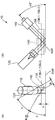
- the first reflecting member 13A-1 of the reflecting member 13A is arranged at the first calibration position and the reflecting member 13A
- the second reflecting member 13A-2 is disposed at the second calibration position, the illumination light is reflected by the first reflecting member 13A-1, and thereby the illumination light is guided to the standard member 14A, and the sample measurement surface of the sample SM
- the diffuse reflected light of the illumination light diffusely reflected by the standard member 14 is reflected by the second reflecting member 13A-2 so that it has substantially the same optical path as the reflected light of the illumination light reflected by the SMF, and is received by the light receiving optical system 12A. Is done.
- the first reflecting member 13A-1, the second reflecting member 13A-2, and the standard member 14A are attached to the attaching member 25. Therefore, the reflection characteristic measuring apparatus DA and its illumination light receiving optical system 1A in the present embodiment can move the first reflecting member 13A-1, the second reflecting member 13A-2, and the standard member 14 together. Accordingly, the mutual geometric arrangement relationship between the first reflecting member 13A-1, the second reflecting member 13A-2, and the standard member 14 is maintained constant, and even if these are repeatedly rearranged between the calibration position and the standby position. Further, the displacement of the mutual geometric arrangement relationship between the first reflecting member 13A-1, the second reflecting member 13A-2 and the standard member 14 is reduced. As a result, calibration is performed well over a longer period.
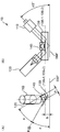
- the measurement plane, the optical axis in the first optical path of illumination light irradiated on the sample measurement surface SMF of the sample SM (that is, the optical axis of the illumination optical system of the illumination system 11B), and the sample measurement surface of the sample SM
- the rotation axis R is inclined at a predetermined angle.
- the spectroscopic unit 2 splits the reflected light of the illumination light and outputs the result to the arithmetic control unit 3.
- the arithmetic control unit 3 obtains a reflection characteristic such as a spectral reflection characteristic in the reflected light of the illumination light based on the output of the spectroscopic unit 2.
- the obtained reflection characteristic is output to the output unit 5 under the control of the arithmetic control unit 3.
- the light shielding state and the non-light shielding state can be switched, and the diffuse reflection of the standard member 14 in the light shielding state.
- This light shielding member is in a light shielding state at least when the reflected light of the illumination light reflected by the sample measurement surface SMF of the sample SM is guided to the spectroscopic unit 2 via the light guide member 6. More specifically, the light shielding member is in a light shielding state at least in the measurement mode.
- an angle formed by the first reflecting surface and the measuring plane is formed on the first reflecting surface and the standard member.
- the optical distance between the first reflection surface and the diffuse reflection surface is equal to the distance between the first reflection surface and the measurement plane.
- the optical system for the reflection characteristic measuring apparatus can move the first reflecting member and the second reflecting member integrally.
- the optical system for the reflection characteristic measuring device can move the first reflecting member, the second reflecting member, and the standard member integrally.
- a first driving mechanism that moves the first reflecting member forward and backward with respect to the first calibration position, and the second reflecting member is the second reflecting member.
- a second drive mechanism that moves forward and backward with respect to the calibration position.
- a housing including a measurement opening through which the reflected light of the illumination light reflected by the sample is incident, and a measurement opening light shield that blocks the measurement opening. And a member.
Landscapes
- Physics & Mathematics (AREA)
- Health & Medical Sciences (AREA)
- Life Sciences & Earth Sciences (AREA)
- Chemical & Material Sciences (AREA)
- Analytical Chemistry (AREA)
- Biochemistry (AREA)
- General Health & Medical Sciences (AREA)
- General Physics & Mathematics (AREA)
- Immunology (AREA)
- Pathology (AREA)
- Engineering & Computer Science (AREA)
- Mathematical Physics (AREA)
- Theoretical Computer Science (AREA)
- Spectroscopy & Molecular Physics (AREA)
- Investigating Or Analysing Materials By Optical Means (AREA)
Abstract
Dans le système optique (1A) pour appareil de mesure de la caractéristique de réflexion selon l'invention, au moment d'effectuer l'étalonnage, un premier élément de réflexion (13A-1) est placé en une première position d'étalonnage, et un second élément de réflexion (13A-2) est placé en une seconde position d'étalonnage, de la lumière d'éclairage est guidée vers un élément standard (14A) par réflexion de la lumière d'éclairage au moyen du premier élément de réflexion (13A-1), et la lumière réfléchie par diffusion de la lumière d'éclairage, ladite lumière réfléchie par diffusion ayant été réfléchie par diffusion au moyen de l'élément standard (14A), est réfléchie au moyen du second élément de réflexion (13A-2) de façon que le trajet optique soit sensiblement identique à celui de la lumière réfléchie de la lumière d'éclairage, ladite lumière réfléchie ayant été réfléchie au moyen d'un échantillon (SM).
Priority Applications (1)
| Application Number | Priority Date | Filing Date | Title |
|---|---|---|---|
| JP2013514971A JP5672376B2 (ja) | 2011-05-13 | 2012-04-19 | 反射特性測定装置用光学系および反射特性測定装置 |
Applications Claiming Priority (2)
| Application Number | Priority Date | Filing Date | Title |
|---|---|---|---|
| JP2011-107814 | 2011-05-13 | ||
| JP2011107814 | 2011-05-13 |
Publications (1)
| Publication Number | Publication Date |
|---|---|
| WO2012157190A1 true WO2012157190A1 (fr) | 2012-11-22 |
Family
ID=47176544
Family Applications (1)
| Application Number | Title | Priority Date | Filing Date |
|---|---|---|---|
| PCT/JP2012/002716 Ceased WO2012157190A1 (fr) | 2011-05-13 | 2012-04-19 | Système optique pour appareil de mesure de la caractéristique de réflexion, et appareil de mesure de la caractéristique de réflexion |
Country Status (2)
| Country | Link |
|---|---|
| JP (1) | JP5672376B2 (fr) |
| WO (1) | WO2012157190A1 (fr) |
Cited By (3)
| Publication number | Priority date | Publication date | Assignee | Title |
|---|---|---|---|---|
| JP2015138028A (ja) * | 2014-01-23 | 2015-07-30 | ベーユプスィロンカー−ガードネルゲーエムベーハー | 光学測定機器の較正のための装置 |
| CN109964105A (zh) * | 2016-11-14 | 2019-07-02 | 浜松光子学株式会社 | 分光测量装置和分光测量系统 |
| CN113203707A (zh) * | 2020-01-31 | 2021-08-03 | 精工爱普生株式会社 | 处理装置 |
Citations (5)
| Publication number | Priority date | Publication date | Assignee | Title |
|---|---|---|---|---|
| JPS5278484A (en) * | 1975-12-25 | 1977-07-01 | Asahi Optical Co Ltd | Apparatus for measuring reflection factor of mirror surface |
| JPS6388430A (ja) * | 1986-09-30 | 1988-04-19 | Shimadzu Corp | 絶対反射率測定装置 |
| JPH05142036A (ja) * | 1991-05-10 | 1993-06-08 | Mitsui Mining & Smelting Co Ltd | 光センサ装置 |
| JP2002022656A (ja) * | 2000-07-04 | 2002-01-23 | Shimadzu Corp | 分光光度計 |
| JP2007506976A (ja) * | 2003-09-23 | 2007-03-22 | メトロソル・インコーポレーテツド | 基準合わせ型真空紫外線反射率計 |
Family Cites Families (1)
| Publication number | Priority date | Publication date | Assignee | Title |
|---|---|---|---|---|
| FR2710564B1 (fr) * | 1993-10-01 | 1995-11-24 | Iname Int | Dispositif de reconnaissance et/ou de tri de fruits ou légumes, procédé et utilisation correspondants. |
-
2012
- 2012-04-19 JP JP2013514971A patent/JP5672376B2/ja active Active
- 2012-04-19 WO PCT/JP2012/002716 patent/WO2012157190A1/fr not_active Ceased
Patent Citations (5)
| Publication number | Priority date | Publication date | Assignee | Title |
|---|---|---|---|---|
| JPS5278484A (en) * | 1975-12-25 | 1977-07-01 | Asahi Optical Co Ltd | Apparatus for measuring reflection factor of mirror surface |
| JPS6388430A (ja) * | 1986-09-30 | 1988-04-19 | Shimadzu Corp | 絶対反射率測定装置 |
| JPH05142036A (ja) * | 1991-05-10 | 1993-06-08 | Mitsui Mining & Smelting Co Ltd | 光センサ装置 |
| JP2002022656A (ja) * | 2000-07-04 | 2002-01-23 | Shimadzu Corp | 分光光度計 |
| JP2007506976A (ja) * | 2003-09-23 | 2007-03-22 | メトロソル・インコーポレーテツド | 基準合わせ型真空紫外線反射率計 |
Cited By (6)
| Publication number | Priority date | Publication date | Assignee | Title |
|---|---|---|---|---|
| JP2015138028A (ja) * | 2014-01-23 | 2015-07-30 | ベーユプスィロンカー−ガードネルゲーエムベーハー | 光学測定機器の較正のための装置 |
| CN109964105A (zh) * | 2016-11-14 | 2019-07-02 | 浜松光子学株式会社 | 分光测量装置和分光测量系统 |
| EP3540394A4 (fr) * | 2016-11-14 | 2020-11-11 | Hamamatsu Photonics K.K. | Dispositif de mesure spectroscopique et système de spectrométrie |
| US10928249B2 (en) | 2016-11-14 | 2021-02-23 | Hamamatsu Photonics K.K. | Spectroscopic measurement device and spectrometry system |
| CN109964105B (zh) * | 2016-11-14 | 2021-07-06 | 浜松光子学株式会社 | 分光测量装置和分光测量系统 |
| CN113203707A (zh) * | 2020-01-31 | 2021-08-03 | 精工爱普生株式会社 | 处理装置 |
Also Published As
| Publication number | Publication date |
|---|---|
| JP5672376B2 (ja) | 2015-02-18 |
| JPWO2012157190A1 (ja) | 2014-07-31 |
Similar Documents
| Publication | Publication Date | Title |
|---|---|---|
| JP2005207982A5 (fr) | ||
| KR20130106810A (ko) | 반사율 측정 장치, 반사율 측정 방법, 막두께 측정 장치 및 막두께 측정 방법 | |
| KR101987506B1 (ko) | 측정 장치 및 측정 방법 | |
| JP2012215569A (ja) | 携帯型色計測デバイス | |
| US9551612B2 (en) | Tandem dispersive range monochromator | |
| JP5672376B2 (ja) | 反射特性測定装置用光学系および反射特性測定装置 | |
| HU186069B (en) | Spectrophotometer operating on discrete wave-lengths | |
| KR100495604B1 (ko) | 광학 자동 측정 방법 | |
| CN110678722A (zh) | 分光光度计 | |
| US8717557B2 (en) | Spectrophotometer and method for determining performance thereof | |
| JP5985629B2 (ja) | 測光装置 | |
| US20160238525A1 (en) | V-block refractometer | |
| KR101823197B1 (ko) | 광학 측정 장치 | |
| KR20070110140A (ko) | 코팅 처리의 광학 모니터링을 위한 측정 시스템 | |
| JP2007327923A (ja) | 分光測定装置および分光測定装置の調整方法 | |
| US8625092B2 (en) | Apparatus for measuring a spectral distribution of a translucent printed product produced with a printing device | |
| WO2018020779A1 (fr) | Dispositif de mesure optique | |
| JP4660693B2 (ja) | 光学特性測定装置 | |
| JP2010281696A (ja) | 発光素子測定装置及び発光素子測定方法 | |
| US7787125B2 (en) | Apparatus for measuring a spectral distribution of a printed product produced with a printing device | |
| JP2001235370A (ja) | 反射特性測定装置 | |
| CN117441094A (zh) | 经稳定化且经调制的双通道宽带光源 | |
| JP2025092247A (ja) | 分光分析装置及び分光分析方法 | |
| CN118392306A (zh) | 光源测量装置、光源测量系统及光源测量方法 | |
| JP4569316B2 (ja) | 分光測色装置 |
Legal Events
| Date | Code | Title | Description |
|---|---|---|---|
| 121 | Ep: the epo has been informed by wipo that ep was designated in this application |
Ref document number: 12785106 Country of ref document: EP Kind code of ref document: A1 |
|
| ENP | Entry into the national phase |
Ref document number: 2013514971 Country of ref document: JP Kind code of ref document: A |
|
| NENP | Non-entry into the national phase |
Ref country code: DE |
|
| 122 | Ep: pct application non-entry in european phase |
Ref document number: 12785106 Country of ref document: EP Kind code of ref document: A1 |