WO2012157489A1 - 車両のインレットボックスの取付け構造 - Google Patents
車両のインレットボックスの取付け構造 Download PDFInfo
- Publication number
- WO2012157489A1 WO2012157489A1 PCT/JP2012/061873 JP2012061873W WO2012157489A1 WO 2012157489 A1 WO2012157489 A1 WO 2012157489A1 JP 2012061873 W JP2012061873 W JP 2012061873W WO 2012157489 A1 WO2012157489 A1 WO 2012157489A1
- Authority
- WO
- WIPO (PCT)
- Prior art keywords
- inlet box
- hole
- outer panel
- flange
- vehicle
- Prior art date
- Legal status (The legal status is an assumption and is not a legal conclusion. Google has not performed a legal analysis and makes no representation as to the accuracy of the status listed.)
- Ceased
Links
Images








Classifications
-
- B—PERFORMING OPERATIONS; TRANSPORTING
- B60—VEHICLES IN GENERAL
- B60K—ARRANGEMENT OR MOUNTING OF PROPULSION UNITS OR OF TRANSMISSIONS IN VEHICLES; ARRANGEMENT OR MOUNTING OF PLURAL DIVERSE PRIME-MOVERS IN VEHICLES; AUXILIARY DRIVES FOR VEHICLES; INSTRUMENTATION OR DASHBOARDS FOR VEHICLES; ARRANGEMENTS IN CONNECTION WITH COOLING, AIR INTAKE, GAS EXHAUST OR FUEL SUPPLY OF PROPULSION UNITS IN VEHICLES
- B60K15/00—Arrangement in connection with fuel supply of combustion engines or other fuel consuming energy converters, e.g. fuel cells; Mounting or construction of fuel tanks
- B60K15/03—Fuel tanks
- B60K15/04—Tank inlets
- B60K15/05—Inlet covers
-
- B—PERFORMING OPERATIONS; TRANSPORTING
- B60—VEHICLES IN GENERAL
- B60J—WINDOWS, WINDSCREENS, NON-FIXED ROOFS, DOORS, OR SIMILAR DEVICES FOR VEHICLES; REMOVABLE EXTERNAL PROTECTIVE COVERINGS SPECIALLY ADAPTED FOR VEHICLES
- B60J5/00—Doors
-
- E—FIXED CONSTRUCTIONS
- E06—DOORS, WINDOWS, SHUTTERS, OR ROLLER BLINDS IN GENERAL; LADDERS
- E06B—FIXED OR MOVABLE CLOSURES FOR OPENINGS IN BUILDINGS, VEHICLES, FENCES OR LIKE ENCLOSURES IN GENERAL, e.g. DOORS, WINDOWS, BLINDS, GATES
- E06B7/00—Special arrangements or measures in connection with doors or windows
-
- H—ELECTRICITY
- H02—GENERATION; CONVERSION OR DISTRIBUTION OF ELECTRIC POWER
- H02G—INSTALLATION OF ELECTRIC CABLES OR LINES, OR OF COMBINED OPTICAL AND ELECTRIC CABLES OR LINES
- H02G3/00—Installations of electric cables or lines or protective tubing therefor in or on buildings, equivalent structures or vehicles
- H02G3/02—Details
- H02G3/08—Distribution boxes; Connection or junction boxes
-
- B—PERFORMING OPERATIONS; TRANSPORTING
- B60—VEHICLES IN GENERAL
- B60K—ARRANGEMENT OR MOUNTING OF PROPULSION UNITS OR OF TRANSMISSIONS IN VEHICLES; ARRANGEMENT OR MOUNTING OF PLURAL DIVERSE PRIME-MOVERS IN VEHICLES; AUXILIARY DRIVES FOR VEHICLES; INSTRUMENTATION OR DASHBOARDS FOR VEHICLES; ARRANGEMENTS IN CONNECTION WITH COOLING, AIR INTAKE, GAS EXHAUST OR FUEL SUPPLY OF PROPULSION UNITS IN VEHICLES
- B60K1/00—Arrangement or mounting of electrical propulsion units
- B60K1/04—Arrangement or mounting of electrical propulsion units of the electric storage means for propulsion
-
- B—PERFORMING OPERATIONS; TRANSPORTING
- B60—VEHICLES IN GENERAL
- B60K—ARRANGEMENT OR MOUNTING OF PROPULSION UNITS OR OF TRANSMISSIONS IN VEHICLES; ARRANGEMENT OR MOUNTING OF PLURAL DIVERSE PRIME-MOVERS IN VEHICLES; AUXILIARY DRIVES FOR VEHICLES; INSTRUMENTATION OR DASHBOARDS FOR VEHICLES; ARRANGEMENTS IN CONNECTION WITH COOLING, AIR INTAKE, GAS EXHAUST OR FUEL SUPPLY OF PROPULSION UNITS IN VEHICLES
- B60K15/00—Arrangement in connection with fuel supply of combustion engines or other fuel consuming energy converters, e.g. fuel cells; Mounting or construction of fuel tanks
- B60K15/03—Fuel tanks
- B60K15/04—Tank inlets
- B60K2015/0458—Details of the tank inlet
-
- B—PERFORMING OPERATIONS; TRANSPORTING
- B60—VEHICLES IN GENERAL
- B60K—ARRANGEMENT OR MOUNTING OF PROPULSION UNITS OR OF TRANSMISSIONS IN VEHICLES; ARRANGEMENT OR MOUNTING OF PLURAL DIVERSE PRIME-MOVERS IN VEHICLES; AUXILIARY DRIVES FOR VEHICLES; INSTRUMENTATION OR DASHBOARDS FOR VEHICLES; ARRANGEMENTS IN CONNECTION WITH COOLING, AIR INTAKE, GAS EXHAUST OR FUEL SUPPLY OF PROPULSION UNITS IN VEHICLES
- B60K15/00—Arrangement in connection with fuel supply of combustion engines or other fuel consuming energy converters, e.g. fuel cells; Mounting or construction of fuel tanks
- B60K15/03—Fuel tanks
- B60K15/04—Tank inlets
- B60K15/05—Inlet covers
- B60K2015/0507—Arrangements for adjusting the inlet cover
-
- B—PERFORMING OPERATIONS; TRANSPORTING
- B60—VEHICLES IN GENERAL
- B60K—ARRANGEMENT OR MOUNTING OF PROPULSION UNITS OR OF TRANSMISSIONS IN VEHICLES; ARRANGEMENT OR MOUNTING OF PLURAL DIVERSE PRIME-MOVERS IN VEHICLES; AUXILIARY DRIVES FOR VEHICLES; INSTRUMENTATION OR DASHBOARDS FOR VEHICLES; ARRANGEMENTS IN CONNECTION WITH COOLING, AIR INTAKE, GAS EXHAUST OR FUEL SUPPLY OF PROPULSION UNITS IN VEHICLES
- B60K15/00—Arrangement in connection with fuel supply of combustion engines or other fuel consuming energy converters, e.g. fuel cells; Mounting or construction of fuel tanks
- B60K15/03—Fuel tanks
- B60K15/04—Tank inlets
- B60K15/05—Inlet covers
- B60K2015/0515—Arrangements for closing or opening of inlet cover
- B60K2015/053—Arrangements for closing or opening of inlet cover with hinged connection to the vehicle body
-
- B—PERFORMING OPERATIONS; TRANSPORTING
- B60—VEHICLES IN GENERAL
- B60K—ARRANGEMENT OR MOUNTING OF PROPULSION UNITS OR OF TRANSMISSIONS IN VEHICLES; ARRANGEMENT OR MOUNTING OF PLURAL DIVERSE PRIME-MOVERS IN VEHICLES; AUXILIARY DRIVES FOR VEHICLES; INSTRUMENTATION OR DASHBOARDS FOR VEHICLES; ARRANGEMENTS IN CONNECTION WITH COOLING, AIR INTAKE, GAS EXHAUST OR FUEL SUPPLY OF PROPULSION UNITS IN VEHICLES
- B60K15/00—Arrangement in connection with fuel supply of combustion engines or other fuel consuming energy converters, e.g. fuel cells; Mounting or construction of fuel tanks
- B60K15/03—Fuel tanks
- B60K15/04—Tank inlets
- B60K15/05—Inlet covers
- B60K2015/0553—Details concerning the inlet box or bowl in the vehicle car body panel
Definitions
- the present invention relates to a structure for attaching an inlet box to an outer panel of a vehicle.
- an operator first enters an inlet 103 into a hole 103 formed in a recess of the outer panel 101 of the vehicle as shown in FIG.
- the cylindrical portion 113 of the box 110 is inserted.
- the flange 114 formed on the peripheral edge of the opening of the inlet box 110 is overlapped on the peripheral edge 102 of the hole 103 from the outside.
- the flange 114 of the inlet box 110 is screwed to the peripheral edge 102 of the hole 103 from the outside of the outer panel 101.
- the outer panel 101 is connected to a lid portion (not shown) configured so as to be able to close the recess of the outer panel 101 via a hinge mechanism (not shown).
- the flange 114 of the inlet box 110 is screwed to the peripheral edge 102 of the hole 103 of the outer panel 101 from the outside. Therefore, since the removal of the inlet box 110 becomes easy when the lid is open, it is desired to prevent the inlet box 110 from being stolen. In addition, since the head of the screw can be seen when the lid is open, an improvement in appearance is also desired.
- the inlet box 110 is screwed to the peripheral edge 102 of the hole 103 of the outer panel 101 from the inside.
- the inlet box 110 is generally attached to the side surface of the outer panel 101. For this reason, if a force is applied to the inlet box 110 when screwing, the inlet box 110 may come off the outer panel 101 or be displaced from the screwing position. For this reason, it is desired to improve the working efficiency of screwing the inlet box 110 to the outer panel 101 from the inside.
- a vehicle inlet box mounting structure includes a vehicle outer panel including a hole, an inlet box inserted into the hole, a flange formed at an opening periphery of the inlet box, and an inlet.
- Engaging claws formed on the outer peripheral surface of the box.
- the flange is set from the outside to the periphery of the hole, and is screwed from the inside to the periphery of the hole of the outer panel.
- the engaging claw engages with the periphery of the hole from the inside of the outer panel, and can be detached from the periphery of the hole by an engagement releasing operation from the inside of the outer panel.
- the inlet box when the inlet box is screwed to the outer panel, it is possible to prevent the inlet box from being detached from the outer panel or being displaced even if a force is applied to the inlet box. Therefore, the working efficiency when the inlet box is screwed to the outer panel is improved. By improving the work efficiency, for example, the inlet box can be easily replaced.
- the engaging claw of the inlet box is configured to be disengaged from the peripheral edge of the hole portion by an engagement releasing operation from the inner side of the outer panel. For this reason, when replacing the inlet box, the engaging claw does not prevent removal of the inlet box.
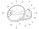
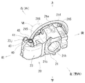
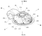
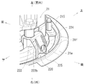
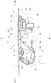
- FIG. 1 It is a perspective view of a vehicle provided with the attachment structure of the inlet box concerning this embodiment. It is a perspective view of the assembly concerning this embodiment seen from the front side. It is a perspective view of an outer panel and an assembly seen from the vehicle inside. It is a perspective view of the back side of the inlet box seen from the front upper part. It is a perspective view of the back side of the inlet box looked up from back lower direction. It is VI arrow enlarged view of FIG. It is an VII arrow enlarged view of FIG. It is a cross-sectional view showing the assembly structure of the assembly and the inlet box. It is an IX arrow enlarged view of FIG. It is a plane sectional view showing a hinge mechanism which connects an inlet box and a lid.
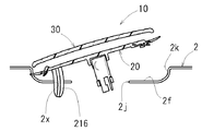
- FIG. 6 is a side view of the outer panel and the assembly at the first stage set on the outer panel. It is a side view of the assembly in the 2nd step
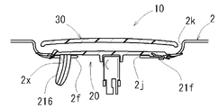
- FIG. 10 is a side view of the outer panel and the assembly in a third stage set on the outer panel. It is a perspective view of the conventional inlet box attachment structure of a vehicle.
- FIGS. 8 A vehicle inlet box mounting structure according to an embodiment of the present invention will be described with reference to FIGS.
- an electric vehicle (EV), a plug-in hybrid electric vehicle (PHEV) or the like equipped with a battery that can be charged by an external power source has a power supply side connector connected when the battery is charged.
- Charging connector 50 is provided.
- the charging connector 50 is accommodated in the resin inlet box 20.
- the inlet box 20 is assembled as a part of a resin inlet box assembly 10 (hereinafter simply referred to as an assembly).
- the assembly 10 is connected to a resin lid 30 that opens and closes the opening 22 of the inlet box 20, and the lid 30 is connected to the inlet box 20 in a rotatable state.
- a hinge mechanism 40 In the following description, front and rear, left and right, and top and bottom mean front and rear, left and right, and top and bottom of the vehicle, respectively.
- the inlet box 20 is attached to a predetermined position on the side surface of the outer panel 2 of the vehicle, as shown in FIGS.
- the inlet box 20 according to the present embodiment is attached to an outer panel on the right side of the vehicle, and the left side of the inlet box 20 corresponds to the inside (front side) of the vehicle compartment, and the right side corresponds to the outside (back side) of the vehicle compartment.
- the inlet box 20 includes a box main body portion 21 that houses the charging connector 50 (see FIG. 8), and an overhang portion 23 that protrudes laterally from the box main body portion 21. It is equipped with.
- the box body portion 21 is formed in a substantially cup shape having an opening 22 (see FIG. 8) and a bottom portion 21b.
- the overhang portion 23 is formed in a substantially square bag shape opened on the box body portion 21 side.
- a circular flange 21f (see FIGS. 4 and 5) is formed on the periphery of the opening 22 of the box body 21.
- a rubber seal 21e is attached along the periphery of the flange 21f.
- a floor surface opening 21h through which a cable (not shown) connected to the charging connector 50 is passed is formed in the bottom 21b of the box body 21.
- bolts 215 for attaching the inlet box 20 to the outer panel 2 of the vehicle are formed on the rear surface of the flange 21f.
- the bolt 215 protrudes at a substantially right angle to the back surface of the flange 21f.
- the bolts 215 are provided at intervals of about 90 ° in the circumferential direction of the flange 21 f so that two bolts 215 are arranged on the upper side and the lower side of the box main body 21. .
- the outer panel 2 is formed with a circular recess 2k that can accommodate the lid 30 and the like.
- a substantially cross-shaped hole 2j into which the inlet box 20 can be inserted is formed at the bottom of the recess 2k.
- bolt holes 2b through which four bolts 215 provided on the flange 21f are respectively inserted are formed in the peripheral edge 2f of the hole 2j at the bottom of the recess 2k. The four bolts 215 are passed through the bolt holes 2b, and the nuts N are fastened to the respective bolts 215 from the inner side of the outer panel 2, whereby the inlet box 20 is attached to the vehicle.
- a positioning pin 216 is formed on the rear side of the flange 21 f at the rear side position of the front upper bolt 215.
- auxiliary positioning pins 217 are formed on the rear side of the flange 21 f at the front position of the rear lower bolt 215.
- the positioning pin 216 and the auxiliary positioning pin 217 are pins for positioning the bolt 215 with respect to the bolt hole 2b.
- a positioning hole 2x and an auxiliary positioning hole 2y are formed in the peripheral edge 2f of the hole 2j of the outer panel 2.
- the positioning pin 216 and the auxiliary positioning pin 217 are passed through the positioning hole 2x and the auxiliary positioning hole 2y, respectively.
- the positioning pin 216 is formed with a predetermined length so that the inlet box 20 can be passed through the positioning hole 2x from the initial stage when the inlet box 20 is inserted into the hole 2j.
- the positioning pin 216 is curved so as to coincide with the insertion locus of the inlet box 20 described later.
- the auxiliary positioning pin 217 is passed through the auxiliary positioning hole 2y at the end of insertion of the inlet box 20, that is, immediately before the bolt 215 of the flange 21f is passed through the bolt hole 2b of the outer panel 2.
- an engagement claw 220 is formed at the rear end of the box body 21.
- the engaging claw 220 is a claw that prevents the inlet box 20 from being detached from the outer panel 2 in a state where the flange 21f is set on the peripheral edge 2f of the hole 2j of the outer panel 2 from the outside. That is, with the bolts 215, positioning pins 216, and auxiliary positioning pins 217 of the inlet box 20 inserted through the bolt holes 2b, positioning holes 2x, and auxiliary positioning holes 2y of the outer panel 2, the engaging claws 220 are located on the inner side of the outer panel 2. Can engage with the peripheral edge 2f of the hole 2j of the outer panel 2.
- the engaging claw 220 includes a claw body 224 and a claw support portion 222 (see FIG. 9).
- the claw support portion 222 has a groove shape having a substantially U-shaped cross section that is open on the flange 21f side, and has a rear wall portion 222b.
- the claw body 224 is formed by cutting the rear wall portion 222b so as to have a U-shaped slit, and is integrated with the groove-shaped bottom portion.
- the claw body 224 can be bent in the radial direction of the box body 21 with the vicinity of the bottom of the groove shape of the claw support 222 as a fulcrum, as shown in FIG. 9.
- the claw body 224 slides on the peripheral edge 2f of the hole 2j, so that the claw body 224 resists elastic force and reaches the position of the two-dot chain line. Elastically deforms.
- An edge portion 225 is formed in parallel to the flange 21f at the tip of the claw body 224, that is, the portion farthest from the fulcrum.
- the edge part 225 can be engaged with the peripheral edge 2f of the hole 2j from the inner side of the outer panel 2. As indicated by a two-dot chain line in FIG. 9, the edge portion 225 engaged with the peripheral edge 2 f is bent to the peripheral edge by manually bending the claw main body 224 against the elastic force inward in the radial direction of the box main body portion 21. 2f can be removed.
- the lid 30 includes a disc-shaped lid body 32 that closes the opening 22 while being coaxially disposed with the flange 21 f, and an inlet through the hinge mechanism 40. And a lever 35 of a substantially U-shaped lid 30 connected to the box 20.
- the lid body 32 is set to have an outer diameter that is substantially equal to the flange 21f, and is accommodated in the recess 2k of the outer panel 2. As shown in FIG. 8, the lid body 32 is configured by combining a front surface plate portion 32f and a back surface plate portion 32u. A cover portion 32c of the charging connector 50 is formed at the center position of the back plate portion 32u.
- the lever 35 of the lid 30 can be rotated around the rotation center of the hinge mechanism 40.
- the rotating end portion of the lever 35 of the lid portion 30 is connected to the front end portion of the back plate portion 32 u of the lid body 32.
- the lever 35 of the lid portion 30 can be housed in the overhang portion 23 of the inlet box 20.
- the hinge mechanism 40 is a mechanism that connects the lid portion 30 to the inlet box 20 in a state in which the lid portion 30 can be rotated almost horizontally.
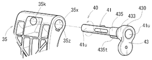
- the hinge mechanism 40 includes a hinge pin 41 and a lever 43 that is provided at the proximal end portion of the hinge pin 41 and is attached to the hinge pin 41 so as not to be relatively rotatable.
- the hinge mechanism 40 further includes a coil spring 45 (biasing member) provided between the lever 43 and the overhang portion 23 of the inlet box 20.
- the hinge pin 41 includes a pin main body 41 u and a cylindrical portion 430.
- the base end portion of the pin main body 41u is integrated with the cylindrical portion 430.
- the cylindrical portion 430 includes a large-diameter large-diameter cylindrical portion 433 located near the proximal end of the pin main body 41u and a small-diameter detent portion 435 located near the distal end.
- an upper bearing portion 23j and a lower bearing portion 23k are formed at positions closer to the outer side on the upper wall portion and the lower wall portion of the front end of the overhang portion 23 of the inlet box 20, respectively.
- the large-diameter cylindrical portion 433 of the hinge pin 41 and the tip end portion of the pin main body 41u are respectively passed through the upper bearing portion 23j and the lower bearing portion 23k.
- the anti-rotation portion 435 includes a protrusion 435t formed on the outer peripheral surface and extending in the axial direction.
- a protrusion 435t formed on the outer peripheral surface and extending in the axial direction.
- two side surfaces 435s and 435u (contact surfaces) arranged outward in the circumferential direction are centered on the rotation center O of the hinge pin 41 as seen in a cross section as shown in FIG. It is formed so as to overlap with the radius line R. That is, the protrusion 435t has a substantially sectoral cross section.
- the lever 43 is a substantially bowl-shaped plate member in which two disks are connected as shown in FIG. One disk constituting the lever 43 is integrated with the large-diameter cylindrical portion 433 of the hinge pin 41.
- the base end of the lever 35 of the lid 30 has a through hole 35k through which the pin main body 41u passes and a rotation stop hole 35x (hinge) through which the rotation prevention portion 435 passes. Hole) is formed.
- a groove 35z into which the protrusion 435t is fitted from the axial direction is formed in the rotation stop hole 35x.
- the groove 35z has two side surfaces 351 and 352 (abutment surfaces) arranged so as to face each other in the circumferential direction, as shown in FIG. 12, with a radius centered on the rotation center O of the hinge pin 41 as viewed in cross section. It is formed so as to overlap the line R.
- One side 351 of the protrusion 435t abuts one side 435s of the groove 35z, and the other side 352 of the protrusion 435t abuts the other side 435u of the groove 35z.
- the protrusion 435t and the groove 35z have side surfaces that are in surface contact with each other, and are thus engaged in the circumferential direction. That is, the side surfaces 435s and 435u of the protrusion 435t and the side surfaces 351 and 352 of the groove 35z are provided perpendicular to the direction of the rotational force.
- the coil spring 45 (biasing member) is mounted between the lever 43 of the hinge mechanism 40 and the overhanging portion 23 of the inlet box 20.
- the coil spring 45 can apply a rotational force (biasing force) in the direction to fully close the opening 22 of the inlet box 20 and the direction to fully open the opening 22 to the lid portion 30. Since the hinge pin 41 and the cover part 30 are prevented from rotating by fitting the protrusion 435t and the groove part 35z, the rotational force by the coil spring 45 is generated from the lever 43 and the rotation stopper part 435 of the hinge pin 41 from the protrusion 435t and the groove part. It adds to the cover part 30 via 35z.
- the operator first inserts the lever 35 of the lid 30 from the opening 22 of the inlet box 20 to the position of the overhang 23 as shown in FIG. 8.
- the through hole 35k and the rotation preventing hole 35x of the lever 35 of the lid portion 30 are held coaxially by the lower bearing portion 23k and the upper bearing portion 23j provided in the overhang portion 23 of the inlet box 20.
- the hinge pin 41 is inserted from the upper bearing portion 23j side of the inlet box 20.
- the pin main body 41u of the hinge pin 41 is passed through the through hole 35k of the lever 35 of the lid portion 30, and the tip end portion of the pin main body 41u is the lower bearing portion 23k of the inlet box 20 as shown in FIG. Will be passed through.
- the rotation prevention portion 435 of the hinge pin 41 is passed through the rotation prevention hole 35x of the lever 35 of the lid portion 30, and as shown in FIG. 12, the protrusion 435t of the rotation prevention portion 435 is a groove portion 35z of the rotation prevention hole 35x. Mates with.
- the large-diameter cylindrical portion 433 of the hinge pin 41 is passed through the upper bearing portion 23j of the inlet box 20 as shown in FIG. Thereby, the lever 35 and the hinge pin 41 of the cover part 30 can be rotated around the upper bearing part 23j and the lower bearing part 23k of the inlet box 20.
- the overhanging portion 23 of the inlet box 20 is inserted into the hole 2j of the outer panel 2 with the assembly 10 inclined.
- the tip of the positioning pin 216 formed on the flange 21 f of the inlet box 20 is passed through the positioning hole 2 x formed on the peripheral edge 2 f of the hole 2 j of the outer panel 2.
- the inlet box 20 is inserted into the hole 2j of the outer panel 2 as shown in FIG.
- the bolt 215 of the flange 21f and the bolt hole 2b of the outer panel 2 can be aligned.
- the bolt 215 of the flange 21f is passed through the bolt hole 2b of the peripheral edge 2f of the hole 2j. In this way, as shown in FIGS. 8 and 15, the flange 21 f and the lid body 32 of the lid portion 30 are accommodated in the circular recess 2 k of the outer panel 2.
- the flange 21f is set on the peripheral edge 2f of the hole 2j of the outer panel 2.
- the claw body 224 of the engagement claw 220 of the inlet box 20 against the edge of the hole 2j
- the claw body 224 is deformed radially inward against the elastic force and passes through the hole 2j (see FIG. 9). (See dotted line).
- the edge part 225 of the claw body 224 becomes the inner side of the outer panel 2.
- the nut 10 is fastened from the inside of the outer panel 2 to each bolt 215 of the flange 21 f, and the assembly 10 is attached to the outer panel 2.
- the edge portion 225 of the claw body 224 of the inlet box 20 is engaged with the peripheral edge 2 f of the hole portion 2 j of the outer panel 2. It is possible to prevent the inlet box 20 from coming off or from being displaced.
- the mounting structure of the vehicle inlet box 20 includes the vehicle outer panel 2 including the hole 2j, the inlet box 20 inserted into the hole 2j, and the flange formed on the periphery of the opening 22 of the inlet box 20. 21 f and an engaging claw 220 formed on the outer peripheral surface of the inlet box 20.
- the flange 21f is set from the outside to the peripheral edge 2f of the hole 2j and is screwed to the peripheral edge 2f of the hole 2j of the outer panel 2 from the inside.
- the engaging claw 220 engages with the peripheral edge 2f of the hole 2j from the inside of the outer panel 2 when the flange 21f is set on the peripheral edge 2f of the hole 2j, and also releases the hole by the disengagement operation from the inner side of the outer panel 2. It can deviate from the peripheral edge 2f of the portion 2j.
- the inlet box 20 when the inlet box 20 is screwed to the outer panel 2, it is possible to prevent the inlet box 20 from being detached from the outer panel 2 or causing a displacement even if a force pushing the inlet box 20 outward is applied. . Therefore, the work efficiency when the inlet box 20 is screwed to the outer panel 2 is improved. By improving the work efficiency, for example, the inlet box 20 can be easily replaced.
- the engaging claw 220 of the inlet box 20 is disengaged from the peripheral edge 2f of the hole 2j by an engagement releasing operation from the inner side of the outer panel 2. For this reason, when replacing the inlet box 20, the engaging claw 220 does not prevent removal of the inlet box 20.
- the mounting structure of the inlet box 20 further includes positioning holes 2x formed in the peripheral edge 2f of the hole 2j of the outer panel 2 and positioning pins 216 provided in the flange 21f of the inlet box 20.
- the positioning pin 216 is curved in accordance with the insertion locus of the inlet box 20 into the hole of the outer panel 2 and is inserted through the positioning hole 2x.
- the inlet box 20 can be inserted into the hole 2j of the outer panel 2 with a correct insertion locus. Therefore, even when the shape of the inlet box 20 is complicated, the inlet box 20 can be easily set on the outer panel 2. In addition, the surface of the outer panel 2 is less likely to be wrinkled.
- the mounting structure of the inlet box 20 further includes a lid 30 that opens and closes the opening of the inlet box 20 and a hinge mechanism that connects the lid 30 to the inlet box 20.
- the hinge mechanism is provided between the anti-rotation hole 35x (hinge hole) provided in the lid portion 30, the hinge pin 41 inserted into the anti-rotation hole 35x, and between the anti-rotation hole 35x and the hinge pin 41 and is fitted to each other.
- a protrusion 435t and a groove 35z that restrict relative rotation between the lid 30 and the hinge pin 41, a coil spring 45 (biasing member) that biases the hinge pin 41 so as to hold the lid 30 in a predetermined position, and Is provided.
- the protrusion 435t and the groove 35z include contact surfaces that are perpendicular to the direction of the rotational force applied by the coil spring 45 and contact each other.
- the mounting structure of the inlet box 20 further includes a charging connector in the inlet box to which a power supply side connector is connected when the vehicle battery is charged. Thereby, the mounting structure of the inlet box 20 can be applied to vehicles such as electric vehicles and plug-in hybrid electric vehicles, and the above-described effects can be obtained.
- a plurality of engaging claws 220 can be provided, and the plurality of engaging claws can be arranged along the circumferential direction of the inlet box 20, for example.
- the protrusion 435t of the hinge pin 41 of the lever 43 and the groove portion 35z of the rotation stop hole 35x (hinge hole) of the lid portion 30 can be provided not only in one set but also in the circumferential direction.
- the inlet box may be a fuel inlet box including a fuel filler port in addition to the inlet box 20 including the charging connector 50.
Landscapes
- Engineering & Computer Science (AREA)
- Mechanical Engineering (AREA)
- Civil Engineering (AREA)
- Structural Engineering (AREA)
- Sustainable Energy (AREA)
- Sustainable Development (AREA)
- Life Sciences & Earth Sciences (AREA)
- Chemical & Material Sciences (AREA)
- Combustion & Propulsion (AREA)
- Transportation (AREA)
- Architecture (AREA)
- Arrangement Or Mounting Of Propulsion Units For Vehicles (AREA)
- Cooling, Air Intake And Gas Exhaust, And Fuel Tank Arrangements In Propulsion Units (AREA)
- Hybrid Electric Vehicles (AREA)
Abstract
Description
Claims (4)
- 車両のインレットボックスの取付け構造であって、
穴部を備える車両のアウタパネルと、
前記穴部に挿入されるインレットボックスと、
前記インレットボックスの開口周縁に形成されるフランジで、前記穴部の周縁に外側からセットされるとともに、前記アウタパネルの前記穴部の周縁に内側からネジ止めされる前記フランジと、
前記インレットボックスの外周面に形成される係合爪で、前記フランジが前記穴部の周縁にセットされたときに前記アウタパネルの内側から前記穴部の周縁に係合するとともに、前記アウタパネルの内側からの係合解除操作により前記穴部の周縁から外れ得る前記係合爪と、
を備える車両のインレットボックスの取付け構造。 - 請求項1に記載の車両のインレットボックスの取付け構造であって、
前記アウタパネルの前記穴部の周縁に形成された位置決め孔と、
前記インレットボックスの前記フランジに設けられる位置決めピンで、前記アウタパネルの前記穴部への前記インレットボックスの挿入軌跡に合わせて湾曲しており、前記位置決め孔に挿通される前記位置決めピンと、
を備える車両のインレットボックスの取付け構造。 - 請求項1又は請求項2に記載の車両のインレットボックスの取付け構造であって、
前記インレットボックスの開口を開閉する蓋部と、
前記蓋部を前記インレットボックスに連結するヒンジ機構とを備え、
前記ヒンジ機構は、
前記蓋部に設けられたヒンジ孔と、
前記ヒンジ孔に挿し込まれるヒンジピンと、
前記ヒンジ孔と前記ヒンジピンとの間に設けられ、互いに嵌合することにより前記蓋部と前記ヒンジピンの相対回転を規制する突条と溝部と、
前記蓋部を所定位置に保持するように前記ヒンジピンを付勢する付勢部材と、を備え、
前記突条及び前記溝部は、前記付勢部材により加わる回転力の方向に対して垂直でかつ互いに当接する当接面を備える、
車両のインレットボックスの取付け構造。 - 請求項1から請求項3のいずれか1項に記載の車両のインレットボックスの取付け構造であって、
車両のバッテリを充電する際に電源側のコネクタが接続される充電コネクタが前記インレットボックス内に設けられる、
車両のインレットボックスの取付け構造。
Priority Applications (3)
| Application Number | Priority Date | Filing Date | Title |
|---|---|---|---|
| US13/808,560 US9083163B2 (en) | 2011-05-16 | 2012-05-09 | Inlet box mounting structure of car |
| CN201280001909.8A CN103025555B (zh) | 2011-05-16 | 2012-05-09 | 车辆的嵌入箱的安装结构 |
| EP12785265.5A EP2581250B1 (en) | 2011-05-16 | 2012-05-09 | Structure for mounting vehicle inlet box |
Applications Claiming Priority (2)
| Application Number | Priority Date | Filing Date | Title |
|---|---|---|---|
| JP2011-109342 | 2011-05-16 | ||
| JP2011109342A JP5636566B2 (ja) | 2011-05-16 | 2011-05-16 | 車両のインレットボックスの取付け構造 |
Publications (1)
| Publication Number | Publication Date |
|---|---|
| WO2012157489A1 true WO2012157489A1 (ja) | 2012-11-22 |
Family
ID=47176819
Family Applications (1)
| Application Number | Title | Priority Date | Filing Date |
|---|---|---|---|
| PCT/JP2012/061873 Ceased WO2012157489A1 (ja) | 2011-05-16 | 2012-05-09 | 車両のインレットボックスの取付け構造 |
Country Status (5)
| Country | Link |
|---|---|
| US (1) | US9083163B2 (ja) |
| EP (1) | EP2581250B1 (ja) |
| JP (1) | JP5636566B2 (ja) |
| CN (1) | CN103025555B (ja) |
| WO (1) | WO2012157489A1 (ja) |
Cited By (1)
| Publication number | Priority date | Publication date | Assignee | Title |
|---|---|---|---|---|
| JP2015157505A (ja) * | 2014-02-21 | 2015-09-03 | トヨタ自動車株式会社 | 車両の充電部 |
Families Citing this family (27)
| Publication number | Priority date | Publication date | Assignee | Title |
|---|---|---|---|---|
| JP5920146B2 (ja) * | 2012-09-27 | 2016-05-18 | 豊田合成株式会社 | フューエルインレットボックスのシール構造 |
| DE102013222686A1 (de) * | 2013-11-07 | 2015-05-21 | Volkswagen Aktiengesellschaft | Klappenmodul |
| US20160280061A1 (en) * | 2013-11-19 | 2016-09-29 | Illinois Tool Works Inc. | A fuel filler assembly for a vehicle |
| WO2015079960A1 (ja) * | 2013-11-28 | 2015-06-04 | 八千代工業株式会社 | 燃料タンクのシール構造 |
| DE102014115907A1 (de) | 2014-10-31 | 2016-05-04 | Dr. Ing. H.C. F. Porsche Aktiengesellschaft | Ladevorrichtung für ein elektrisch antreibbares Fahrzeug |
| US10179518B2 (en) | 2014-11-14 | 2019-01-15 | Ricky Jay Henderson | Power docking port system with tetrahedral charging probe |
| CN105172580A (zh) * | 2015-09-25 | 2015-12-23 | 重庆博荣拓尔科技有限公司 | 一种防松动油箱 |
| CN105172581A (zh) * | 2015-09-25 | 2015-12-23 | 重庆博荣拓尔科技有限公司 | 一种油箱盖 |
| CN105172582A (zh) * | 2015-09-25 | 2015-12-23 | 重庆博荣拓尔科技有限公司 | 一种防滑油箱盖 |
| US20170101022A1 (en) * | 2015-10-12 | 2017-04-13 | Revitalize Charging Solutions, Inc. | Apparatus and method for dual automobile electric charger |
| IT201600104772A1 (it) * | 2016-10-18 | 2018-04-18 | Cebi Italy Spa | Sistema per la chiusura di un portello del serbatoio carburante. |
| CN107042769A (zh) * | 2017-03-16 | 2017-08-15 | 重庆国翰能源发展有限公司 | 一种家庭用电动汽车识别及充电系统 |
| JP2018192925A (ja) * | 2017-05-18 | 2018-12-06 | ダイキョーニシカワ株式会社 | フューエルケース組立体 |
| JP7003779B2 (ja) * | 2018-03-23 | 2022-01-21 | トヨタ自動車株式会社 | 車両用給油部構造 |
| JP7587344B2 (ja) | 2018-04-12 | 2024-11-20 | レーヴェンシュタイン メディカル テクノロジー エス.アー. | データ伝送をするためのシステム |
| FR3087160B1 (fr) * | 2018-10-10 | 2021-05-21 | Renault Sas | Systeme de montage d'un bol de trappe a carburant |
| DE102018125209A1 (de) * | 2018-10-11 | 2020-04-16 | Bayerische Motoren Werke Aktiengesellschaft | Tank- oder Ladeklappenanordnung |
| JP7233307B2 (ja) * | 2019-05-31 | 2023-03-06 | ダイキョーニシカワ株式会社 | フューエルリッド装置の取付構造 |
| DE102019119091B4 (de) * | 2019-07-15 | 2022-02-10 | Illinois Tool Works Inc. | Lade- oder tankmulde und verfahren zum herstellen hiervon |
| JP7489263B2 (ja) * | 2020-08-20 | 2024-05-23 | 西川ゴム工業株式会社 | シール部材取付構造 |
| CN116783090A (zh) * | 2021-01-27 | 2023-09-19 | 浙江智马达智能科技有限公司 | 一种汽车充电口盖结构及汽车 |
| JP7649097B2 (ja) * | 2021-01-28 | 2025-03-19 | 株式会社Fts | 蓋の取付構造 |
| JP7649098B2 (ja) * | 2021-01-28 | 2025-03-19 | 株式会社Fts | 蓋の取付構造 |
| JP7563343B2 (ja) * | 2021-09-07 | 2024-10-08 | トヨタ自動車株式会社 | 車両のフューエルインレット部構造 |
| US11794821B2 (en) * | 2022-02-14 | 2023-10-24 | Honda Motor Co., Ltd. | Vehicle fender assembly including a charge port assembly |
| JP7597064B2 (ja) * | 2022-03-22 | 2024-12-10 | トヨタ自動車株式会社 | 充電インレット装置 |
| JP7838453B2 (ja) | 2022-11-10 | 2026-04-01 | 豊田合成株式会社 | リッド開閉装置 |
Citations (6)
| Publication number | Priority date | Publication date | Assignee | Title |
|---|---|---|---|---|
| JPS57165514U (ja) * | 1981-03-11 | 1982-10-19 | ||
| JPH0528731U (ja) * | 1991-06-14 | 1993-04-16 | ダイハツ工業株式会社 | フユーエルインレツトボツクスのシール構造 |
| JPH1134674A (ja) * | 1997-07-18 | 1999-02-09 | Suzuki Motor Corp | フューエルリッドの取付方法及びその取付構造 |
| JP2005125949A (ja) | 2003-10-24 | 2005-05-19 | Honda Motor Co Ltd | フューエルアダプタ構造 |
| JP2010203208A (ja) * | 2009-03-06 | 2010-09-16 | Toyota Auto Body Co Ltd | 車両の蓋材開閉構造 |
| JP2010280243A (ja) * | 2009-06-02 | 2010-12-16 | Mitsubishi Motors Corp | リッド装置 |
Family Cites Families (18)
| Publication number | Priority date | Publication date | Assignee | Title |
|---|---|---|---|---|
| JPS58139328U (ja) * | 1982-03-17 | 1983-09-19 | スズキ株式会社 | 自動車の燃料注入口 |
| US5090760A (en) * | 1990-01-29 | 1992-02-25 | Wheeler Basil W | Break-away gas fill guard |
| JPH0613924U (ja) | 1992-07-29 | 1994-02-22 | トヨタ車体株式会社 | 給油口構造 |
| JPH0671246U (ja) | 1993-03-23 | 1994-10-04 | 日野自動車工業株式会社 | 車両の燃料注入口装置 |
| US5906406A (en) * | 1997-06-25 | 1999-05-25 | General Motors Corporation | Fuel filler pocket assembly |
| DE10157395B4 (de) * | 2001-11-23 | 2019-08-01 | Volkswagen Ag | Einsatztopf für ein Tankklappenmodul eines Fahrzeuges, insbesondere eines Kraftfahrzeuges |
| DE20305291U1 (de) | 2003-04-01 | 2003-06-18 | Dr. Schneider Engineering GmbH, 96317 Kronach | Schwenklager für eine Klappe, insbesondere für die Klappe vor einem Tankverschluss in einem Kraftfahrzeug |
| DE20311149U1 (de) | 2003-07-18 | 2003-10-16 | Dr. Schneider Engineering GmbH, 96317 Kronach | Tankmulde aus Kunststoff |
| JP4406411B2 (ja) * | 2006-03-31 | 2010-01-27 | 本田技研工業株式会社 | フューエルリッド構造 |
| KR100844672B1 (ko) * | 2006-11-13 | 2008-07-07 | 기아자동차주식회사 | 차량의 연료도어 장착용 하우징 |
| JP5191813B2 (ja) * | 2007-07-26 | 2013-05-08 | 株式会社ニフコ | 固定具、被固定部材の固定構造、被固定部材の固定方法及び固定具の固定解除方法 |
| JP4367559B2 (ja) | 2007-08-10 | 2009-11-18 | トヨタ自動車株式会社 | 車両 |
| JP2009061974A (ja) * | 2007-09-07 | 2009-03-26 | Honda Motor Co Ltd | フューエルリッド部構造 |
| DE102008047464A1 (de) | 2008-09-17 | 2010-04-15 | Dr.Ing.H.C.F.Porsche Aktiengesellschaft | Tankklappenmodul |
| FR2936448B1 (fr) * | 2008-09-29 | 2011-06-17 | Peugeot Citroen Automobiles Sa | Dispositif pour monter avec precision une trappe a carburant dans une ouverture realisee dans la tole de la caisse d'un vehicule automobile |
| JP5198361B2 (ja) * | 2009-06-04 | 2013-05-15 | トヨタ自動車株式会社 | リテーナ構造 |
| JP5360480B2 (ja) * | 2009-06-22 | 2013-12-04 | 株式会社ニフコ | 留め具 |
| WO2010151635A2 (en) * | 2009-06-24 | 2010-12-29 | Huawei Technologies Co., Ltd. | Method and apparatus for electric powered vehicle recharging safety |
-
2011
- 2011-05-16 JP JP2011109342A patent/JP5636566B2/ja active Active
-
2012
- 2012-05-09 US US13/808,560 patent/US9083163B2/en active Active
- 2012-05-09 CN CN201280001909.8A patent/CN103025555B/zh not_active Expired - Fee Related
- 2012-05-09 WO PCT/JP2012/061873 patent/WO2012157489A1/ja not_active Ceased
- 2012-05-09 EP EP12785265.5A patent/EP2581250B1/en not_active Not-in-force
Patent Citations (6)
| Publication number | Priority date | Publication date | Assignee | Title |
|---|---|---|---|---|
| JPS57165514U (ja) * | 1981-03-11 | 1982-10-19 | ||
| JPH0528731U (ja) * | 1991-06-14 | 1993-04-16 | ダイハツ工業株式会社 | フユーエルインレツトボツクスのシール構造 |
| JPH1134674A (ja) * | 1997-07-18 | 1999-02-09 | Suzuki Motor Corp | フューエルリッドの取付方法及びその取付構造 |
| JP2005125949A (ja) | 2003-10-24 | 2005-05-19 | Honda Motor Co Ltd | フューエルアダプタ構造 |
| JP2010203208A (ja) * | 2009-03-06 | 2010-09-16 | Toyota Auto Body Co Ltd | 車両の蓋材開閉構造 |
| JP2010280243A (ja) * | 2009-06-02 | 2010-12-16 | Mitsubishi Motors Corp | リッド装置 |
Non-Patent Citations (1)
| Title |
|---|
| See also references of EP2581250A4 * |
Cited By (2)
| Publication number | Priority date | Publication date | Assignee | Title |
|---|---|---|---|---|
| JP2015157505A (ja) * | 2014-02-21 | 2015-09-03 | トヨタ自動車株式会社 | 車両の充電部 |
| US9610850B2 (en) | 2014-02-21 | 2017-04-04 | Toyota Jidosha Kabushiki Kaisha | Vehicle charging unit |
Also Published As
| Publication number | Publication date |
|---|---|
| EP2581250A4 (en) | 2014-05-14 |
| CN103025555A (zh) | 2013-04-03 |
| US9083163B2 (en) | 2015-07-14 |
| US20140060920A1 (en) | 2014-03-06 |
| EP2581250A1 (en) | 2013-04-17 |
| EP2581250B1 (en) | 2016-08-03 |
| JP2012240443A (ja) | 2012-12-10 |
| CN103025555B (zh) | 2015-08-26 |
| JP5636566B2 (ja) | 2014-12-10 |
Similar Documents
| Publication | Publication Date | Title |
|---|---|---|
| JP5636566B2 (ja) | 車両のインレットボックスの取付け構造 | |
| JP5585362B2 (ja) | 充電ポート用カバーの配設構造 | |
| WO2012161087A1 (ja) | 車両のインレットボックスアッセンブリ | |
| JP5268868B2 (ja) | 充電自動車用の充電コネクタのロック機構 | |
| JP6017857B2 (ja) | 車両用リッドロック装置 | |
| US20140235087A1 (en) | Charging port locking device | |
| JP5741196B2 (ja) | 充電コネクタの取り付け構造 | |
| CN105673653B (zh) | 锁定装置 | |
| JP2012195215A (ja) | 充電用コネクタ | |
| JP2012076605A (ja) | 充電ポート用カバーの配設構造 | |
| WO2020100397A1 (ja) | フードロック装置 | |
| JP2011183878A (ja) | 車両用シート | |
| JP5355035B2 (ja) | 車両用リッドロック装置 | |
| JP5530889B2 (ja) | 充電ポート用カバーの配設構造 | |
| JP2014108669A (ja) | ドアミラー | |
| KR101819577B1 (ko) | 체결 조립체 | |
| JP5798062B2 (ja) | 受電装置 | |
| JP5347944B2 (ja) | 車両の充電口構造 | |
| JP2012015058A (ja) | 車両側コネクタ | |
| CN112455588A (zh) | 电能装置、电动车及二轮车架 | |
| JP5786683B2 (ja) | 車両用充電リッド部構造 | |
| JP2013011094A (ja) | 車両用ロック装置 | |
| WO2019220812A1 (ja) | 樹脂部品 | |
| WO2018070068A1 (ja) | パーキングブレーキレバー装置 | |
| CN102255181B (zh) | 插座及具备该插座的充电装置 |
Legal Events
| Date | Code | Title | Description |
|---|---|---|---|
| WWE | Wipo information: entry into national phase |
Ref document number: 201280001909.8 Country of ref document: CN |
|
| REEP | Request for entry into the european phase |
Ref document number: 2012785265 Country of ref document: EP |
|
| WWE | Wipo information: entry into national phase |
Ref document number: 2012785265 Country of ref document: EP |
|
| 121 | Ep: the epo has been informed by wipo that ep was designated in this application |
Ref document number: 12785265 Country of ref document: EP Kind code of ref document: A1 |
|
| WWE | Wipo information: entry into national phase |
Ref document number: 13808560 Country of ref document: US |
|
| NENP | Non-entry into the national phase |
Ref country code: DE |