WO2012160672A1 - Transformateur - Google Patents
Transformateur Download PDFInfo
- Publication number
- WO2012160672A1 WO2012160672A1 PCT/JP2011/061984 JP2011061984W WO2012160672A1 WO 2012160672 A1 WO2012160672 A1 WO 2012160672A1 JP 2011061984 W JP2011061984 W JP 2011061984W WO 2012160672 A1 WO2012160672 A1 WO 2012160672A1
- Authority
- WO
- WIPO (PCT)
- Prior art keywords
- transformer
- magnetic flux
- mounting members
- electromagnetic shield
- coil
- Prior art date
- Legal status (The legal status is an assumption and is not a legal conclusion. Google has not performed a legal analysis and makes no representation as to the accuracy of the status listed.)
- Ceased
Links
Images



Classifications
-
- H—ELECTRICITY
- H01—ELECTRIC ELEMENTS
- H01F—MAGNETS; INDUCTANCES; TRANSFORMERS; SELECTION OF MATERIALS FOR THEIR MAGNETIC PROPERTIES
- H01F27/00—Details of transformers or inductances, in general
- H01F27/34—Special means for preventing or reducing unwanted electric or magnetic effects, e.g. no-load losses, reactive currents, harmonics, oscillations, leakage fields
- H01F27/36—Electric or magnetic shields or screens
-
- H—ELECTRICITY
- H01—ELECTRIC ELEMENTS
- H01F—MAGNETS; INDUCTANCES; TRANSFORMERS; SELECTION OF MATERIALS FOR THEIR MAGNETIC PROPERTIES
- H01F27/00—Details of transformers or inductances, in general
- H01F27/34—Special means for preventing or reducing unwanted electric or magnetic effects, e.g. no-load losses, reactive currents, harmonics, oscillations, leakage fields
- H01F27/36—Electric or magnetic shields or screens
- H01F27/366—Electric or magnetic shields or screens made of ferromagnetic material
Definitions
- the present invention relates to a transformer, and more particularly to a structure for supporting an electromagnetic shield included in the transformer.
- Oil-filled transformers generally include a transformer body and a tank that houses the transformer body.
- the transformer body includes a high voltage coil, a low voltage coil, and an iron core.
- the tank is filled with insulating oil, and the transformer body is immersed in the insulating oil.
- the tank is generally made of steel.
- an electromagnetic shield is attached to the inner wall of the tank.
- Patent Document 1 discloses an electromagnetic shield used for a transformer.
- the electromagnetic shield includes a plurality of laminated magnetic thin plates and a pair of metal plates sandwiching the plurality of magnetic thin plates.
- a plurality of seats are provided to attach the electromagnetic shield to the tank. These seat plates are connected to the electromagnetic shield body and the inner wall of the tank by welding. As a result, the electromagnetic shield is attached to the tank.
- a closed circuit is formed by two seat plates, one of a pair of metal plates sandwiching a plurality of magnetic thin plates, and a steel plate to which the seat plates are attached.
- the purpose of the present invention is to more effectively reduce transformer losses.
- a transformer according to an aspect of the present invention includes a tank and a transformer body housed in the tank.
- the transformer body includes an iron core and a coil wound around the iron core.
- the transformer further includes a plurality of electromagnetic shields.
- Each of the plurality of electromagnetic shields includes a plurality of magnetic thin plates stacked on each other, a pair of metal plates sandwiching the plurality of magnetic thin plates, and a plurality of attachment members each connected to the pair of metal plates.
- the plurality of attachment members are arranged at positions where the sum of leakage magnetic fluxes interlinking regions between the first and second attachment members adjacent to each other among the plurality of attachment members becomes zero.
- stray load loss of the transformer can be reduced. Therefore, according to the present invention, the loss of the transformer can be reduced.
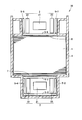
- FIG. 2 is a cross-sectional view of a part of the transformer taken along line II-II in FIG. 1.
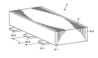
- FIG. 7 is a diagram showing one unit of the electromagnetic shields 5-1 to 5-7 shown in FIG.
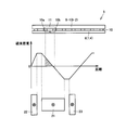
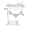
- FIG. 4 is a diagram for explaining leakage magnetic flux generated from a coil 2. It is a figure explaining the electromagnetic shield which concerns on the comparative example of this Embodiment, and the circulating current which arises in the electromagnetic shield. It is a figure explaining one structural example of the electromagnetic shield which concerns on embodiment of this invention, and the leakage magnetic flux which links the area
- FIG. 6 is a diagram illustrating an example of a support structure for an electromagnetic shield according to Embodiment 2.
- FIG. It is the figure which showed the other example of the support structure of the electromagnetic shield which concerns on Embodiment 2.
- FIG. 6 is a diagram illustrating an example of a support structure for an electromagnetic shield according to Embodiment 2.
- FIG. It is the figure which showed the other example of the support structure of the electromagnetic shield which concerns on Embodiment 2.
- FIG. 1 is a schematic diagram of a transformer according to an embodiment of the present invention.
- transformer 50 includes a plurality of iron cores 1 and a plurality of coils 2 wound around the plurality of iron cores 1.
- the plurality of iron cores 1 and the plurality of coils 2 constitute a transformer body.
- Each of the plurality of iron cores 1 has an annular shape.
- the coil 2 is wound around two adjacent iron cores 1.
- the insulator 3 covers the coil 2.
- the coil 2 includes a high voltage coil 21 and low voltage coils 22 and 23.
- the high voltage coil 21 is disposed between the low voltage coils 22 and 23.
- the transformer 50 further has a tank 4 for accommodating the transformer body. Although not shown, the inside of the tank 4 is filled with insulating oil. During operation of the transformer 50, insulating oil is circulated to cool the transformer body.
- the tank 4 is formed of a steel material.
- FIG. 2 is a cross-sectional view of a part of the transformer along the line II-II in FIG.
- the transformer 50 includes an iron core 1, a coil 2, electromagnetic shields 5-1 to 5-7, a tongue wedge 6, and a tongue support 7.
- the insulator 3 is not shown in FIG.
- the tongue wedge 6 is arranged on the uppermost surface of the iron core 1.
- the tongue support 7 is disposed so as to penetrate the opening of the coil 2 and supports the iron core 1.
- the tongue support 7 is passed between the flanges at the bottom of the tank.
- the tongue wedge 6 and the tongue support 7 are made of steel.
- the iron core 1 is fixed by the tongue wedge 6 and the tongue support 7.
- the high voltage coil 21 and the low voltage coils 22 and 23 are arranged coaxially.
- FIG. 3 is a diagram showing one unit of the electromagnetic shields 5-1 to 5-7 shown in FIG. 2 and 3, the electromagnetic shield 5 includes a plurality of magnetic thin plates 8 stacked on each other, metal plates 9-1 and 9-2 sandwiching the plurality of magnetic thin plates 8, and a plurality of seat plates 10-. 1 to 10-3.
- the metal plates 9-1 and 9-2 and the seat plates 10-1 to 10-3 are made of iron or stainless steel.
- Seat plates 10-1 to 10-3 function as mounting members. Each of the seat plates 10-1 to 10-3 is connected to the metal plates 9-1 and 9-2 by welding. The seat plates 10-1 to 10-3 are further attached to the inner wall of the tank 4, the tongue wedge 6 or the tongue support 7 by welding. Thus, the electromagnetic shield 5 is attached at a desired position. Specifically, the electromagnetic shield 5-1 is attached to the tongue support 7. The electromagnetic shields 5-2, 5-3, and 5-4 are attached to the inner wall of the tank 4 (lower tank). The electromagnetic shields 5-5 and 5-7 are attached to the inner wall of the tank 4. The electromagnetic shield 5-6 is attached to the tongue wedge 6. In this embodiment, a metal plate is shown as the mounting member. However, the shape of the mounting member is not limited as shown in FIG.
- the electromagnetic shields 5-1 to 5-7 are provided to prevent the leakage magnetic flux from entering the tank 4, the tongue wedge 6 or the tongue support 7.
- FIG. 4 is a diagram for explaining the leakage magnetic flux generated from the coil 2.
- the density of the leakage magnetic flux reaches a positive peak value or a negative peak value in a region between the high voltage coil and the low voltage coil.
- the density of the leakage magnetic flux reaches a positive peak value in the region between the high voltage coil 21 and the low voltage coil 22.
- the density of the leakage magnetic flux reaches a negative peak value.
- the relationship between the two regions and the positive peak value and the negative peak value of the leakage magnetic flux density may be opposite to the above relationship.
- FIG. 5 is a diagram for explaining an electromagnetic shield according to a comparative example of the present embodiment and a circulating current generated in the electromagnetic shield.
- the hatched area in the graph indicates the integrated value of the magnetic flux density of the leakage magnetic flux interlinking the area between the two seat plates 10a and 10b (in the subsequent figures). The same).
- the integrated value of the magnetic flux density over the range of the positive value of the magnetic flux density is different from the absolute value of the integrated value of the magnetic flux density over the range of the negative value of the magnetic flux density. For this reason, the integrated value of the magnetic flux density of the leakage magnetic flux interlinking the region between the two seat plates 10a and 10b does not become zero.
- the circulating current 11 flows in a closed circuit formed by the seat plates 10a and 10b, the tongue wedge 6 and the metal plate 9-1.
- the circulating current is also applied to the closed circuit located on the opposite side to the side shown in FIG. 5, that is, the closed circuit formed by the seat plates 10a and 10b, the tongue wedge 6 and the metal plate 9-2. Flowing. Further, the same phenomenon occurs in the electromagnetic shield attached to the tongue support 7 or the tank 4. Stray load loss occurs when the circulating current 11 flows through the closed circuit.
- the plurality of seat plates 10 are arranged so that the total sum of the leakage magnetic flux interlinking the region between the two seat plates is zero.
- the arrangement of the plurality of seat plates 10 will be described in detail below.
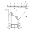
- FIG. 6 is a diagram for explaining one configuration example of the electromagnetic shield according to the embodiment of the present invention and the leakage magnetic flux interlinking the region between the two seat plates of the electromagnetic shield.
- One of the two seats is attached at a position corresponding to the positive peak value of the leakage flux density, and the other is attached at a position corresponding to the negative peak value of the leakage flux density.
- the positive integral value of magnetic flux density and the absolute value of the negative integral value of magnetic flux density become substantially equal. Therefore, the sum total of the leakage magnetic flux interlinking the region between the seat plates 10a and 10b can be made substantially zero.
- the density of the leakage magnetic flux reaches a positive peak value in the region between the high voltage coil 21 and the low voltage coil 22.
- the density of the leakage magnetic flux reaches a negative peak value in the region between the high voltage coil 21 and the low voltage coil 23. Therefore, the period L of the density distribution of the leakage magnetic flux can be estimated based on the arrangement of the high voltage coil 21 and the low voltage coils 22 and 23. As a result, the distance d between the two seats can be determined. Further, the positions of the plurality of seat plates 10 can be determined.
- the position of the seat plate may exactly coincide with the peak position of the magnetic flux density, or may be in the vicinity of the peak position.
- FIG. 7 is a diagram for explaining another configuration example of the electromagnetic shield according to the present embodiment and a leakage magnetic flux interlinking the region between the two seat plates of the electromagnetic shield.
- the positive integral value of the magnetic flux density is almost equal to the absolute value of the negative integral value of the magnetic flux density. Therefore, the sum total of the leakage magnetic flux interlinking the region between the seat plates 10a and 10b can be made substantially zero. As a result, stray load loss can be reduced, and transformer loss can be effectively reduced.
- the position of the seat plate is equal to the position corresponding to the positive peak value of the magnetic flux density of the leakage magnetic flux.
- the position of the seat plate need not be limited as described above.
- the integrated value of the magnetic flux density during one period of the magnetic flux density distribution is zero. Therefore, according to the configuration shown in FIG. 7, the degree of freedom in the arrangement of the electromagnetic shield can be increased.
- the distance d between the two seats can be determined according to the following equation.
- m is an integer of 1 or more.
- m is an integer of 1 or more.
- two adjacent seat plates among the plurality of seat plates 10 are attached to a steel material such as a tank wedge as follows. That is, one of the two seats is attached at a position corresponding to the positive peak of the leakage magnetic flux density, and the other is attached at a position corresponding to the negative peak of the leakage magnetic flux density. Thereby, it is possible to reduce the total sum of the leakage magnetic fluxes interlinking the region between the two seat plates (ideally, the total sum of the leakage magnetic fluxes becomes zero).
- the position of the seat plate need not be limited to the position of the peak of the leakage magnetic flux density.
- the electromagnetic shield according to the embodiment of the present invention is attached to at least the tongue portion (the tongue wedge 6 and the tongue support 7). That is, the electromagnetic shield according to the embodiment of the present invention is preferably provided in a region between the iron core and the coil.
- the magnetic flux density of the leakage magnetic flux interlinking the region between the two seat plates is particularly large in the tongue portion. Therefore, the loss of a transformer can be effectively reduced by attaching the electromagnetic shield which concerns on embodiment of this invention to a tongue part.
- the electromagnetic shield according to the embodiment of the present invention is attached not only to the tongue portion but also to the inner wall of the tank 4.
- the electromagnetic shield attached to the tank 4 has a function of preventing leakage magnetic flux from the coil from entering the tank 4. Therefore, the loss of the transformer can be further reduced.
- the distance d between the two seats of the electromagnetic shield is determined to be, for example, 1/2 times or 1 time the period of the density distribution of the leakage magnetic flux.
- the support strength of the electromagnetic shield may decrease.
- a spacer is disposed between two seat plates. Thereby, the fall of the support strength of an electromagnetic shield can be prevented.
- the spacer is formed of an insulator.
- FIG. 8 is a view showing an example of a support structure for an electromagnetic shield according to the second embodiment.
- the insulating spacer 31 is inserted into a part of the region between the two seat plates. That is, in this configuration, the support strength of the electromagnetic shield is increased by the point support by the insulating spacer 31.
- FIG. 9 is a view showing another example of a support structure for an electromagnetic shield according to the second embodiment.
- the insulating spacer 32 is inserted so as to fill the entire area between the two seat plates. That is, in this configuration, the support strength of the electromagnetic shield is increased by the surface support by the insulating spacer 31.
- interval d between the two seats is the same as the interval according to the first embodiment, and therefore the following description will not be repeated.
- the loss of the transformer can be effectively reduced as in the first embodiment. Furthermore, according to Embodiment 2, even when the space
Landscapes
- Engineering & Computer Science (AREA)
- Power Engineering (AREA)
- Regulation Of General Use Transformers (AREA)
Abstract
Priority Applications (4)
| Application Number | Priority Date | Filing Date | Title |
|---|---|---|---|
| US13/984,041 US8928446B2 (en) | 2011-05-25 | 2011-05-25 | Transformer |
| JP2011549778A JP5010055B1 (ja) | 2011-05-25 | 2011-05-25 | 変圧器 |
| CN201180070465.9A CN103503092B (zh) | 2011-05-25 | 2011-05-25 | 变压器 |
| PCT/JP2011/061984 WO2012160672A1 (fr) | 2011-05-25 | 2011-05-25 | Transformateur |
Applications Claiming Priority (1)
| Application Number | Priority Date | Filing Date | Title |
|---|---|---|---|
| PCT/JP2011/061984 WO2012160672A1 (fr) | 2011-05-25 | 2011-05-25 | Transformateur |
Publications (1)
| Publication Number | Publication Date |
|---|---|
| WO2012160672A1 true WO2012160672A1 (fr) | 2012-11-29 |
Family
ID=46844508
Family Applications (1)
| Application Number | Title | Priority Date | Filing Date |
|---|---|---|---|
| PCT/JP2011/061984 Ceased WO2012160672A1 (fr) | 2011-05-25 | 2011-05-25 | Transformateur |
Country Status (4)
| Country | Link |
|---|---|
| US (1) | US8928446B2 (fr) |
| JP (1) | JP5010055B1 (fr) |
| CN (1) | CN103503092B (fr) |
| WO (1) | WO2012160672A1 (fr) |
Cited By (1)
| Publication number | Priority date | Publication date | Assignee | Title |
|---|---|---|---|---|
| JP6594597B1 (ja) * | 2019-03-27 | 2019-10-23 | 三菱電機株式会社 | 静止誘導機器 |
Families Citing this family (5)
| Publication number | Priority date | Publication date | Assignee | Title |
|---|---|---|---|---|
| DE102013226226A1 (de) * | 2012-12-21 | 2014-06-26 | Robert Bosch Gmbh | Induktivladespulenvorrichtung |
| JPWO2017002225A1 (ja) * | 2015-07-01 | 2017-06-29 | 三菱電機株式会社 | 変圧器 |
| EP3654354A1 (fr) * | 2018-11-14 | 2020-05-20 | ABB Schweiz AG | Supports internes pour transformateurs en forme de coque |
| EP4309197A2 (fr) * | 2021-03-19 | 2024-01-24 | Redur Gmbh & Co. KG | Corps de blindage basse tension, transformateur de courant basse tension, agencement de transformateur de courant basse tension ou ensemble électrique basse tension |
| KR102372134B1 (ko) * | 2021-07-23 | 2022-03-08 | 신건일 | 전자파 차폐필터 |
Citations (6)
| Publication number | Priority date | Publication date | Assignee | Title |
|---|---|---|---|---|
| JPS5632423U (fr) * | 1979-08-22 | 1981-03-30 | ||
| JPS5681914A (en) * | 1979-12-10 | 1981-07-04 | Hitachi Ltd | Stationary induction electrical apparatus |
| JPS60219717A (ja) * | 1984-04-16 | 1985-11-02 | Mitsubishi Electric Corp | 静止誘導器の磁気遮へい装置 |
| JPS6310533U (fr) * | 1986-07-09 | 1988-01-23 | ||
| JPS63215028A (ja) * | 1987-03-04 | 1988-09-07 | Mitsubishi Electric Corp | 静止誘導機器用鉄心の組立方法 |
| JP2001244128A (ja) * | 2000-02-25 | 2001-09-07 | Hitachi Ltd | 静止誘導電器 |
Family Cites Families (8)
| Publication number | Priority date | Publication date | Assignee | Title |
|---|---|---|---|---|
| US4156862A (en) * | 1978-02-21 | 1979-05-29 | Westinghouse Electric Corp. | Electrical inductive apparatus having non-magnetic flux shields |
| US4231074A (en) * | 1978-09-18 | 1980-10-28 | General Electric Company | Zero sequence current source for transformer having a nonwound tertiary |
| JPS5632423A (en) | 1979-08-28 | 1981-04-01 | Sunstar Inc | Promotion of thrombolytic activity of urokinase with crude drug extract, and pharmaceutical preparation containing the same |
| JPS6310533A (ja) | 1986-07-02 | 1988-01-18 | Matsushita Electric Ind Co Ltd | 封止金型 |
| JP3311391B2 (ja) * | 1991-09-13 | 2002-08-05 | ヴィエルティー コーポレーション | 漏洩インダクタンス低減トランス、これを用いた高周波回路及びパワーコンバータ並びにトランスにおける漏洩インダクタンスの低減方法 |
| JPH0883721A (ja) * | 1994-09-12 | 1996-03-26 | Toshiba Corp | 三相変圧器 |
| JPH10116741A (ja) * | 1996-10-14 | 1998-05-06 | Toshiba Corp | 静止誘導電器の磁気シールド及びその取付方法 |
| BRPI1008599A2 (pt) * | 2009-02-18 | 2016-03-15 | Abb Research Ltd | derivação magnética, disposição de derivação magnética e dispositivo de força |
-
2011
- 2011-05-25 US US13/984,041 patent/US8928446B2/en not_active Expired - Fee Related
- 2011-05-25 WO PCT/JP2011/061984 patent/WO2012160672A1/fr not_active Ceased
- 2011-05-25 JP JP2011549778A patent/JP5010055B1/ja not_active Expired - Fee Related
- 2011-05-25 CN CN201180070465.9A patent/CN103503092B/zh not_active Expired - Fee Related
Patent Citations (6)
| Publication number | Priority date | Publication date | Assignee | Title |
|---|---|---|---|---|
| JPS5632423U (fr) * | 1979-08-22 | 1981-03-30 | ||
| JPS5681914A (en) * | 1979-12-10 | 1981-07-04 | Hitachi Ltd | Stationary induction electrical apparatus |
| JPS60219717A (ja) * | 1984-04-16 | 1985-11-02 | Mitsubishi Electric Corp | 静止誘導器の磁気遮へい装置 |
| JPS6310533U (fr) * | 1986-07-09 | 1988-01-23 | ||
| JPS63215028A (ja) * | 1987-03-04 | 1988-09-07 | Mitsubishi Electric Corp | 静止誘導機器用鉄心の組立方法 |
| JP2001244128A (ja) * | 2000-02-25 | 2001-09-07 | Hitachi Ltd | 静止誘導電器 |
Cited By (2)
| Publication number | Priority date | Publication date | Assignee | Title |
|---|---|---|---|---|
| JP6594597B1 (ja) * | 2019-03-27 | 2019-10-23 | 三菱電機株式会社 | 静止誘導機器 |
| WO2020194580A1 (fr) * | 2019-03-27 | 2020-10-01 | 三菱電機株式会社 | Dispositif d'induction stationnaire |
Also Published As
| Publication number | Publication date |
|---|---|
| US20130314199A1 (en) | 2013-11-28 |
| CN103503092A (zh) | 2014-01-08 |
| US8928446B2 (en) | 2015-01-06 |
| JPWO2012160672A1 (ja) | 2014-07-31 |
| CN103503092B (zh) | 2016-05-25 |
| JP5010055B1 (ja) | 2012-08-29 |
Similar Documents
| Publication | Publication Date | Title |
|---|---|---|
| JP5010055B1 (ja) | 変圧器 | |
| JP6464582B2 (ja) | 磁気回路部品 | |
| US20180040409A1 (en) | Transformer | |
| TWI595517B (zh) | Static induction electrical appliances | |
| JP6613784B2 (ja) | 変圧器の鉄心支持構造及び鉄心支持方法 | |
| US20120146760A1 (en) | Transformer | |
| JP5414401B2 (ja) | 静止誘導電器 | |
| JP2019149517A (ja) | 電磁機器 | |
| JP5701120B2 (ja) | 変圧器用磁気遮蔽装置 | |
| JP3646595B2 (ja) | 静止誘導電器 | |
| JP2012028642A (ja) | 変圧器 | |
| JP6504936B2 (ja) | 変圧器 | |
| JP5815116B2 (ja) | 静止誘導機器 | |
| KR101573813B1 (ko) | 저손실 하이브리드 변압기 및 그 제조 방법 | |
| JP6491835B2 (ja) | 静止誘導電器 | |
| JP2013065701A (ja) | 静止機器 | |
| JP7176306B2 (ja) | 変圧器 | |
| JP2012004345A (ja) | 静止誘導機器およびその製造方法 | |
| JP2018107224A (ja) | 静止誘導電器 | |
| JP7593733B2 (ja) | 静止誘導機器用ギャップ付鉄心 | |
| JP2009088084A (ja) | 静止誘導電器 | |
| JP6253963B2 (ja) | 静止機器 | |
| JP7149908B2 (ja) | 静止誘導機器 | |
| JP7356852B2 (ja) | 静止誘導電器用鉄心 | |
| JP2008103416A (ja) | 静止誘導電気機器 |
Legal Events
| Date | Code | Title | Description |
|---|---|---|---|
| ENP | Entry into the national phase |
Ref document number: 2011549778 Country of ref document: JP Kind code of ref document: A |
|
| 121 | Ep: the epo has been informed by wipo that ep was designated in this application |
Ref document number: 11866306 Country of ref document: EP Kind code of ref document: A1 |
|
| WWE | Wipo information: entry into national phase |
Ref document number: 13984041 Country of ref document: US |
|
| NENP | Non-entry into the national phase |
Ref country code: DE |
|
| 122 | Ep: pct application non-entry in european phase |
Ref document number: 11866306 Country of ref document: EP Kind code of ref document: A1 |