WO2012160944A1 - Dispositif de récupération de la chaleur sensible d'un gaz de four à coke - Google Patents
Dispositif de récupération de la chaleur sensible d'un gaz de four à coke Download PDFInfo
- Publication number
- WO2012160944A1 WO2012160944A1 PCT/JP2012/061315 JP2012061315W WO2012160944A1 WO 2012160944 A1 WO2012160944 A1 WO 2012160944A1 JP 2012061315 W JP2012061315 W JP 2012061315W WO 2012160944 A1 WO2012160944 A1 WO 2012160944A1
- Authority
- WO
- WIPO (PCT)
- Prior art keywords
- heat
- heat exchange
- tar
- coke oven
- heat medium
- Prior art date
- Legal status (The legal status is an assumption and is not a legal conclusion. Google has not performed a legal analysis and makes no representation as to the accuracy of the status listed.)
- Ceased
Links
Images


Classifications
-
- C—CHEMISTRY; METALLURGY
- C10—PETROLEUM, GAS OR COKE INDUSTRIES; TECHNICAL GASES CONTAINING CARBON MONOXIDE; FUELS; LUBRICANTS; PEAT
- C10K—PURIFYING OR MODIFYING THE CHEMICAL COMPOSITION OF COMBUSTIBLE GASES CONTAINING CARBON MONOXIDE
- C10K1/00—Purifying combustible gases containing carbon monoxide
- C10K1/04—Purifying combustible gases containing carbon monoxide by cooling to condense non-gaseous materials
- C10K1/06—Purifying combustible gases containing carbon monoxide by cooling to condense non-gaseous materials combined with spraying with water
-
- C—CHEMISTRY; METALLURGY
- C10—PETROLEUM, GAS OR COKE INDUSTRIES; TECHNICAL GASES CONTAINING CARBON MONOXIDE; FUELS; LUBRICANTS; PEAT
- C10K—PURIFYING OR MODIFYING THE CHEMICAL COMPOSITION OF COMBUSTIBLE GASES CONTAINING CARBON MONOXIDE
- C10K1/00—Purifying combustible gases containing carbon monoxide
- C10K1/04—Purifying combustible gases containing carbon monoxide by cooling to condense non-gaseous materials
- C10K1/046—Reducing the tar content
-
- C—CHEMISTRY; METALLURGY
- C10—PETROLEUM, GAS OR COKE INDUSTRIES; TECHNICAL GASES CONTAINING CARBON MONOXIDE; FUELS; LUBRICANTS; PEAT
- C10K—PURIFYING OR MODIFYING THE CHEMICAL COMPOSITION OF COMBUSTIBLE GASES CONTAINING CARBON MONOXIDE
- C10K1/00—Purifying combustible gases containing carbon monoxide
- C10K1/08—Purifying combustible gases containing carbon monoxide by washing with liquids; Reviving the used wash liquors
- C10K1/10—Purifying combustible gases containing carbon monoxide by washing with liquids; Reviving the used wash liquors with aqueous liquids
- C10K1/12—Purifying combustible gases containing carbon monoxide by washing with liquids; Reviving the used wash liquors with aqueous liquids alkaline-reacting including the revival of the used wash liquors
- C10K1/121—Purifying combustible gases containing carbon monoxide by washing with liquids; Reviving the used wash liquors with aqueous liquids alkaline-reacting including the revival of the used wash liquors containing NH3 only (possibly in combination with NH4 salts)
-
- F—MECHANICAL ENGINEERING; LIGHTING; HEATING; WEAPONS; BLASTING
- F28—HEAT EXCHANGE IN GENERAL
- F28C—HEAT-EXCHANGE APPARATUS, NOT PROVIDED FOR IN ANOTHER SUBCLASS, IN WHICH THE HEAT-EXCHANGE MEDIA COME INTO DIRECT CONTACT WITHOUT CHEMICAL INTERACTION
- F28C3/00—Other direct-contact heat-exchange apparatus
- F28C3/06—Other direct-contact heat-exchange apparatus the heat-exchange media being a liquid and a gas or vapour
-
- Y—GENERAL TAGGING OF NEW TECHNOLOGICAL DEVELOPMENTS; GENERAL TAGGING OF CROSS-SECTIONAL TECHNOLOGIES SPANNING OVER SEVERAL SECTIONS OF THE IPC; TECHNICAL SUBJECTS COVERED BY FORMER USPC CROSS-REFERENCE ART COLLECTIONS [XRACs] AND DIGESTS
- Y02—TECHNOLOGIES OR APPLICATIONS FOR MITIGATION OR ADAPTATION AGAINST CLIMATE CHANGE
- Y02P—CLIMATE CHANGE MITIGATION TECHNOLOGIES IN THE PRODUCTION OR PROCESSING OF GOODS
- Y02P20/00—Technologies relating to chemical industry
- Y02P20/10—Process efficiency
Definitions
- the present invention relates to a coke oven gas sensible heat recovery device that recovers sensible heat of coke oven gas (COG) generated in a coke oven with high efficiency.
- COG coke oven gas
- COG In the coke production process in which coal is charged into the coking chamber of a coke oven and carbonized in a high temperature reducing atmosphere, COG of about 800 ° C is generated as a by-product. This COG is cooled to about 80 ° C. or less by receiving a cold flush in the process of passing through the riser pipe provided at the top of the coke oven, and further cooled by a gas cooler. It is separated into tar and water and recovered.
- a high boiling point tar fraction of about 150 ° C. is directly sprayed into COG to primarily cool COG to 320 to 330 ° C., and then directly contact with a medium boiling point tar fraction of about 70 ° C. And secondary cooling to about 120 ° C.
- tar is used as a heat medium, and although there is an advantage that it is not necessary to separate the heat medium and tar, the temperature of the tar after heat recovery becomes a low temperature tar with low exergy, There is a major drawback that it is no longer suitable for low pressure steam production. In addition, when it is designed to increase the tar temperature after recovery, volatilized tar appears at 200 ° C. or higher and heat recovery cannot be established.
- Non-Patent Document 1 a method for reforming volatile tar in high-temperature COG to dry gas.
- the tar content that can be dry gasified by the conventional dry gasification method is about 70% of tar (91% dry gasification), and although tar is gasified and the total calorific value of COG increases, For the 30% tar content, the sensible heat of COG after reforming (invariant before and after reforming) cannot be recovered.
- the present invention has been made in consideration of the problems in the conventional COG sensible heat recovery method as described above, and provides a coke oven gas sensible heat recovery apparatus capable of recovering heat from coke oven gas with high efficiency. Is.
- tar condenses and adheres to the surface of the heat medium that is in direct contact, but the specific gravity of tar is reduced by using an existing tar decanter (specific gravity separation tank for water, tar, and tar cake) and a heat medium recovery tank.
- tar decanter specific gravity separation tank for water, tar, and tar cake
- heat medium recovery tank By separating, tar can be prevented from being brought into a subsequent process using the heat of the heat medium.
- the heat medium it is preferable to use a low-melting-point metal, such as tin (melting point: 232 ° C., specific gravity: 7.0), which has a remarkably large specific gravity compared with tar (specific gravity of 1.1). If there is a sufficient specific gravity difference compared to tar, for example, molten salt, gallium or the like having a specific gravity of about 2 can be used.
- the direct heat exchange includes a countercurrent heat exchange in which COG and the heat medium (cooling medium) are in contact with each other and a cocurrent heat exchange in which the COG and the heat medium are in contact with each other in the same direction.
- the heat exchange by direct contact was predicted from the numerical calculation, and the basic design of the sensible heat recovery device was performed.
- the size of the direct contact heat exchange tower is ⁇ 3.6m x H10m (heat exchange effective height)
- the circulation flow rate of tin, which is the heat medium is 422kg / s (3.63 m 3 / min).
- the total power of the two pumps that circulate tin is 120 kW, and the power of the blower that draws COG that rises in the tower against the tin droplets falling in the heat exchange tower is expected to be 30 kW. Is expected to be 27.5 MW.
- the temperature of tin after heat recovery is 500 ° C.
- steam of 315 kt / year can be produced. This can reduce the amount of external fuel that is currently purchased to produce process steam, and can achieve significant cost savings even as pump and blower power charges increase. become.
- the coke oven gas sensible heat recovery apparatus of the present invention that performs heat recovery with high efficiency is a heat exchange tower that directly contacts the coke oven gas generated in the coke oven with the heat medium, and condenses tar on the surface of the heat medium.
- the gist of the present invention is to provide a heat medium recovery tank that collects the heat medium to which tar is attached, separates the tar from the heat medium by specific gravity separation, and recovers the heat medium.
- a heat medium having a heavier specific gravity than the tar can be used as the heat medium.
- a coke oven gas cooled by heat exchange in the heat exchange tower can be guided to sprinkle the water, and a non-condensed tar can be condensed and stored.
- a tar decanter that guides the aqueous water and the condensate from the aqueous water sprinkler to separate the specific gravity.
- the counter-flow coke oven gas sensible heat recovery device has a gas supply / exhaust passage for supplying the coke oven gas from the bottom of the heat exchange tower and drawing it from the top of the heat exchange tower.
- the countercurrent coke oven gas sensible heat recovery device has a passage portion for taking out a part of the heat medium to which tar has adhered to the outside of the heat exchange tower, and the heat medium recovery tank is provided at the outlet portion of the passage portion. Can be provided.
- the heat exchange tower has a droplet receiving portion for receiving the heat medium that has been subjected to heat exchange and has tar attached thereto, and the droplet receiving portion is It can be connected to the entrance of the passage.
- a second spray nozzle can be provided for spraying the heat medium separated in the heat medium recovery tank from below the droplet receiving portion.
- the cocurrent coke oven gas sensible heat recovery apparatus has a second gas supply / exhaust passage that supplies the coke oven gas from the top of the heat exchange tower and draws it from the bottom of the heat exchange tower.
- the heat medium recovery tank can be provided in the lower part of the heat exchange tower.
- the sensible heat of the high temperature coke oven gas can be recovered with high efficiency.
- 1 is an overall configuration diagram of a countercurrent coke oven gas sensible heat recovery apparatus according to the present invention. It is a top view which shows the structure of the basket provided in the heat exchange tower of FIG. It is a graph which shows the particle size distribution of the tin particle sprayed in a heat exchange tower. It is the graph which showed the relationship between the particle
- 1 is an overall configuration diagram of a cocurrent coke oven gas sensible heat recovery device according to the present invention. It is a graph which shows the performance prediction calculation result of the heat exchange tower in a co-current type coke oven gas sensible heat recovery apparatus.
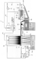
- FIG. 1 is an overall configuration diagram of a counter-current coke oven gas sensible heat recovery device (hereinafter abbreviated as a counter-current type sensible heat recovery device) 1 according to the present invention. It is.
- FIG. 1 An 800 ° C. coke oven gas (hereinafter referred to as COG) generated from a coke oven (not shown) is introduced into the heat exchange tower 2 from the tower lower part 2a of the heat exchange tower 2. It is introduced, rises upward in the tower, and is sent out from the tower top 2b.
- COG coke oven gas
- the main components of COG are hydrogen, methane, and carbon monoxide, but other components such as tar, crude light oil, ammonia, hydrogen sulfide, and hydrogen cyanide are also included.
- the diameter of the heat exchange tower 2 in this embodiment is ⁇ 3.6 m, and the height H is 10 m. The basis of design will be described later.
- a spray mist nozzle (spray nozzle) 3 is disposed in the tower top 2b. From the spray mist nozzle 3, tin as a heating medium has an initial temperature of 250 ° C. above the melting point and an average droplet particle diameter of 1 mm. It is supposed to be sprayed with.
- Tin droplets fall in the tower, while COG flows upward in the tower, thereby forming a countercurrent direct contact heat exchange. During this time, gravity acts downward on the droplet, but it falls slowly because it receives fluid drag by the upwardly flowing COG. As a result, heat exchange can be performed for a longer time than in the case of free-falling.
- the tin particles falling in the tower are heated by contact with the high-temperature COG, whereas the COG is cooled by passing heat to the tin.
- the tar content in the COG falls below 450 ° C., it begins to condense in the heat exchange environment with the surface of the tin droplet, which is the lowest temperature, as the nucleus. Thereby, tar adheres to the surface of the tin droplet.
- the falling tar-attached tin droplets are received by the scissors 4 provided at a height of 5 m from the tin liquid surface L (0 m) and guided to the adjacent heat medium recovery tank 5.
- a plurality of openings are provided in the eaves 4 so as not to completely block the flow of COG rising in the heat exchange tower 2.
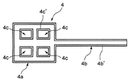
- FIG. 2 is a plan view showing the configuration of the cage 4.
- the tub 4 is a window frame-shaped droplet receiving portion 4a disposed in the horizontal direction in the heat exchange tower 2, and extends linearly from a part of the droplet receiving portion 4a and is inclined downward.
- the droplet receiving portion 4a is provided with a plurality of rectangular openings 4c.
- openings 4c are provided in order to make the closed area occupied in the horizontal section of the heat exchange tower 2 50%, leading 50% of the falling tin particles to the heat medium recovery tank 5 and the remaining 50%. Is directly dropped to the bottom of the heat exchange tower 2.
- 4b ' is a side wall forming the passage 4b
- 4c' is a side wall formed around the opening 4c.
- the opening 4c is not limited to the rectangular shape as long as the closed area can be reduced to 50%.
- the opening 4c may be formed of a punching metal having a large number of circular holes.
- the tar is discharged from the outlet 5a to the outside of the heat medium recovery tank 5 with sensible heat of about 350 ° C., and is used and processed as before after cooling.
- the tin sinking in the lower part of the heat medium recovery tank 5 is positioned at a height of 5 m in the heat exchange tower 2 from the lower part of the heat medium recovery tank 5 by the first vertical pump 6 provided in the heat medium recovery tank 5, that is, It is sent to the lower surface position of the basket 4 and sprayed again into the heat exchange tower 2 from the second spray mist nozzle (second spray nozzle) 7.
- the sprayed tin is brought into direct contact with the high-temperature COG and is heated together with the tin that directly falls through the opening 4c.
- the tin that pours into the liquid tin bath provided in the tower lower part 2a of the heat exchange tower 2 includes tin that does not contain tar that has passed through the heat medium recovery tank 5, and the opening 4c (opening ratio 50%) of the basket 4. Both tin that has fallen through the surface and has tar attached to the surface are present.
- the tar volatilizes again by the time it arrives here and rises in the heat exchange tower 2 together with the high-temperature COG. And as it rises, it cools again and condenses. As a result, the tar gas concentration in the heat exchange tower 2 is slightly increased due to the re-volatilized tar, and is stabilized to a steady state.
- the tin of the liquid tin bath is pumped up from the heat exchange tower 2 by the second vertical pump 8 and used as heat. For example, it is sent to a boiler 9 for producing low-pressure process steam and cooled to 250 ° C. higher than the melting point. And the operation
- the liquid tin and tin vapor also become solid and flow into the tar decanter 10 together with the water.
- the specific gravity is separated from the top in the order of water A, tar B, tar trough C, and the water A is re-charged through the pump 12 and the circulation path 13 except for a part that is extracted and treated with water. Water is sprayed from the water sprinkler 11.
- the tar B is discharged and used / processed, and the tar cake C is scraped and processed by the conveyor 14 as a scraping device.
- ⁇ Tar C is mainly composed of solid particles consisting of fine coal powder and fine coke powder. Solid tin with the highest specific gravity is also mixed in the tar. In order to reuse this solid tin, in this embodiment, the tar soot C containing solid tin is dumped into the heat medium recovery tank 5 as it is.
- Tar C has a specific gravity larger than that of tar and smaller than that of tin. Therefore, a layer is formed so as to be sandwiched between tar and tin.
- the solid tin contained in tar C will dissolve again in an environment of 350 ° C. It becomes liquid and merges with the tin layer stored at the bottom of the heat medium recovery tank 5.
- a shelf 5b is provided at the boundary height between tin and tar, and the tar-medium C in a solid state even at 350 ° C. is heated by the second conveyor 15 as a second scraping device by the heat medium recovery tank 5. It is trying to discharge outside.
- a float type level gauge (not shown) is used to control the first vertical pump 6 for tin feeding. This can be realized.
- the specific gravity of the float is set between tar (specific gravity 1.1) and tin (specific gravity 7), and the height of the tar-tin interface is detected with a float-type liquid level gauge. If it is higher than 5b, the rotational speed of the first saddle pump 6 is increased to increase the pump flow rate and lower the interface height. On the contrary, when the interface height is lower than the shelf 5b, the pump flow rate is reduced by decreasing the rotational speed of the first saddle pump 6 so that the interface height is increased.
- the said tar decanter 10 can use the existing thing.
- a dive weir 4d is provided in the passage portion 4b of the cage 4 so as to prevent the COG from being exhausted in the middle of heat exchange.
- the droplet receiving part 4a is connected to the inlet part of the channel
- One is a second vertical pump 8 for sending again the tin accumulated in the liquid metal bath at the lower part of the heat exchange tower 2 to the spray mist nozzle 3 at the upper part of the heat exchange tower 2, and the temperature range to be handled is 500-600. ° C.
- the other is a first vertical pump 6 that feeds the tin accumulated in the lower part of the heat medium recovery tank 5 to a second spray mist nozzle 7 installed at an intermediate height of the heat exchange tower 2, and the temperature to be handled.
- the range is around 350 ° C.
- vertical (vertical shaft) multistage pumps made by Nissan Kiko Co., Ltd. or Arai Seisakusho Co., Ltd., which put the motor part on the top outside the tank and lower the shaft vertically, are used. can do.
- This type of vertical (vertical shaft) multistage pump is also used for liquid feeding of molten metal and molten salt.
- a third chamber 16 is provided between the seal portion through which the shaft passes and the outside air, and nitrogen is applied to the third chamber 16 at a pressure higher than the pressure on the COG side. To supply. Thereby, even if there is a leak in the seal, either nitrogen is mixed into the COG side or nitrogen leaks into the outside air, so that safety is ensured.
- An example of the sealing material is Inconel fiber heat-resistant expanded graphite gland packing that can be used up to 600 ° C.
- Spray Mist Nozzle As the spray mist nozzle 3 for tin spray, a high temperature packing (for example, metal packing such as copper) that can withstand only the packing is used, and the water mist nozzle is made of tin. Can be used for spraying.
- a high temperature packing for example, metal packing such as copper
- the particle diameter produced by the same mist nozzle is almost the same for both tin and water.
- the pressure becomes 7 times depending on the density ratio (specific gravity ratio) of tin and water.
- the volume flow rate is the same for both.
- 17 is a blower connected to the safety water sprinkler 11, and when this blower 17 is driven, COG supplied to the heat exchange tower 2 rises due to the tin spray, It is discharged out of the counter-flow sensible heat recovery device 1 through the connecting pipe 18 ⁇ the water spraying device 11 ⁇ the discharge pipe 19. That is, the COG supply line 21 and the connecting pipe 18 function as a gas supply / exhaust path for supplying COG from the tower lower portion 2 a of the heat exchange tower 2 and drawing it from the tower top 2 b of the heat exchange tower 2.
- reference numeral 24 denotes a pressure equalizing pipe for equalizing the water spraying device 11 and the tar decanter 10.
- Tin dispersion As a method for evaluating the critical condition of splitting into particles during atomization, the critical Weber number We crit is used which represents the ratio of the drag force received from the fluid to the surface tension force.
- equation (2-2) is proposed as a correction equation for equation (2-1).
- W dot e crit is the critical Weber number when the viscosity of the fluid is zero. That is, in general, the atomized particle diameter is expressed by a function of the Weber number We and the Onesorge number Oh.
- Table 1 shows the physical property values of tin and water, the Reynolds number Re, the Weber number We, and the Ohnesorge number Oh at the particle diameter and injection speed assumed for the tin mist nozzle of this time.
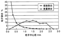
- the particle size distribution is shown in the graph of FIG.
- the graph shows the expected particle size distribution of tin with the selected mist nozzle.
- the number ratio, the mass ratio, and the heat recovery ratio when sprayed in the heat exchange tower 2 for each particle diameter are shown, and the minimum particle diameter is 0.1 mm.
- Tin particles having a particle size of 0.1 mm have a terminal velocity of 2.0 m / s in a COG atmosphere at 800 ° C., so that the COG ascent rate is reduced by a slight wind so that all tin particles can fall down the heat exchange tower 2. If an attempt is made to design at about 2.0 m / s or less, the heat exchange tower 2 becomes large and is not realistic.
- the final velocity of tin particles having a particle diameter of 0.4 mm in an 800 ° C. static COG atmosphere is 11.86 m / s
- the cross-sectional area of the heat exchange tower required for this flow velocity is 10.12 m 2 ( ⁇ 3.6 m )
- a particle having a diameter of less than 0.4 mm, which is 2.9 wt% of the whole, is allowed to be discharged together with the COG, and a method of collecting at a later stage is adopted. This is why the tar decanter 10 is connected to the heat medium recovery tank 5.
- a candidate for a spray mist nozzle for spraying tin is Ikeuchi WP901000 having a fan-shaped injection angle of 90 °, a flow rate of 408 L/min@0.35 MPa (Sn), and a foreign substance passage diameter of 5.6 mm.
- m dot mass flow rate
- Cp constant pressure specific heat
- T temperature
- z vertical distance
- ⁇ thermal conductivity
- D diameter
- ⁇ density
- v speed
- A heat exchange tower cross section
- Nu Nusselt number
- subscripts represent COG: coke oven gas
- m heating medium (tin)
- i particle group number having each center diameter shown in FIG.
- Equation (3-3) The Nusselt number Nu i representing the heat transfer around the heat medium (tin) droplet assuming a spherical shape is expressed by Equation (3-3).
- Re i is the particle Reynolds number of the i-th particle
- Pr is the Prandtl number of COG.
- Equation (3-4) The equation of motion of the particle is obtained by equation (3-4) considering gravity and drag.
- g gravitational acceleration
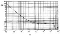
- C Di drag coefficient acting on the particle group i, which is given by the relationship between the particle Reynolds number and the drag coefficient of the sphere in FIG. 4 as a function of Re i .
- the initial velocity of the particles was determined by Bernoulli's equation from the pressure difference before and after the spray slit of the spray mist nozzle. Actually, the initial speed when tin is supplied to the mist nozzle having the characteristics shown in FIG. 3 at 0.35 MPa is estimated to be 10 m / s.
- Equation (3-5) The end velocity u mit of the particle is obtained by equation (3-5) from the balance condition between gravity and drag where the right side of equation (3-4) becomes zero.
- volume occupation ratio R occupied by the liquid metal particles in the tower can be obtained by the equation (3-8).
- the density of the COG in the heat exchange tower changes as it cools.
- the relationship between density and temperature is varied according to the ideal gas equation of state.
- Table 2 shows the physical property values and operating conditions used for this calculation.
- the physical property values at 250 ° C. and 800 ° C. shown in Table 3 are taken out, and a linear approximation formula is constructed and used for the change in temperature. Yes.
- Each physical property value of COG at 250 ° C and 800 ° C is the physical property value of the mixed gas having the composition of COG after purification (H 2 : 58%, CH 4 : 27%, CO: 7%, N 2 : 8%) Is substituted.
- the input power was the sum of the pump power for feeding liquid tin and the COG blower power taking into consideration the pressure loss on the piping to the heat exchange tower and the water sprinkler and the drag on the droplets.
- the combined power of the tin feed pumps is in the order of 0.25 kJ / kg-tin, and the power of the COG blower is in the order of 0.33 to 1.0 kJ / Nm 3 -COG.
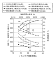
- tower height 10 m and 5 m is shown in the same graph for comparison.
- the ratio of tin and COG supplied to the heat exchange tower 2 is represented by a metal / gas mass flow ratio
- the temperature of tin stored in the tower lower part 2a is represented as a liquid metal bath temperature
- the tin droplets are heated.
- the ratio occupied in the exchange tower 2 is expressed as a liquid enemy space occupation ratio.
- the COG outlet temperature gradually approaches the low temperature of the heat exchanger, that is, the temperature of the sprayed tin 250 ° C. (see L1 and L2).
- the heat exchange efficiency when the tower height is 5 m is 82%.
- the heat exchange efficiency is 95 to 96%. If an attempt is made to obtain a heat exchange efficiency equivalent to that of a tower height of 10 m at a tower height of 5 m, the metal / gas mass flow rate ratio must be significantly increased.
- the liquid metal bath temperature (see L5) will be below 500 ° C.
- L6 has shown the liquid metal bath temperature in case the tower height is 10 m.
- the blower (blower 17 of FIG. 1) is driven by the drag acting on the tin feed pump (first vertical pump 6 and second vertical pump 8 of FIG. 1) and the tin particles. ) And the recovered heat / input power ratio with a tower height of 5 m and the recovered heat / input power ratio with a tower height of 10 m both decrease.
- the space occupancy rate of liquid tin in the space in the heat exchange tower 2 is almost independent of the tower height and substantially corresponds to the metal / gas mass flow rate ratio, Moreover, it is a small value of less than 0.1%. From this calculation result, the following can be understood.
- COG outlet temperature gradually approaches a temperature of 250 ° C. on the low temperature side of the heat exchanger, and its tendency becomes vertically symmetrical with the heat exchange efficiency. If a further low melting point metal such as gallium is used as the heat medium, sufficient heat recovery can be achieved up to 250 ° C. or less.
- the scale of heat utilization equipment such as a boiler using tin as a heat medium increases.
- this temperature should increase due to increased heat recovery, but in practice the metal / gas mass flow ratio increases further, and the increase in the metal / gas mass flow ratio Thus, the temperature of the liquid metal bath tends to decrease.
- the metal / gas mass flow rate ratio is 32 (at this time when the heat exchange height is 10 m.
- the metal / gas mass flow ratio 27 (the heat exchange efficiency at this time is 82%) is the upper limit. Therefore, when the heat exchange efficiency of both is compared, it is more advantageous to adopt a heat exchange height of 10 m.
- the effective height of the heat exchange tower 2 is 10 m and the metal / gas mass flow rate ratio is 32.
- the graph of FIG. 6 shows the temperature distribution of the COG inside the heat exchange tower and the liquid metal particles of each particle size at a heat exchange tower height of 10 m and a metal / gas mass flow rate ratio of 30.6, which is almost equal to the conditions.
- the vertical axis in the graph of FIG. 6 indicates the height of the heat exchange tower 2, and 0 m corresponds to the liquid level L of tin (see FIG. 1), and 10 m corresponds to the top 2b of the tower.
- the horizontal axis indicates the temperature. It shows a case where tin having various particle diameters is injected from a height of 10 m at a temperature of 250 ° C., while COG of 800 ° C. is supplied from the lower part of the heat exchange tower 2.
- particle diameter 0.5 mm the larger the specific surface area is, so that the temperature rises quickly due to heat exchange, but as the particle diameter increases (particle diameter 2.5 mm), the temperature rise slows down.
- the cage 4 is provided at the height of 5 m of the heat exchange tower 2, and at this height of the cage 4, tin with a particle diameter of 2.5 mm rises in temperature from 250 ° C. to 290 ° C.
- the temperature of tin having a particle diameter of 0.5 mm rises to 400 ° C., and the average temperature is about 350 ° C.
- tar components having a boiling point of at least 290 ° C. such as benzo [a] pyrene and phenanthrene, can be recovered. Therefore, it is only necessary to install a grid-like ridge 4 having an aperture ratio of 50% at a position 5 m at the middle height of the heat exchange tower 2.
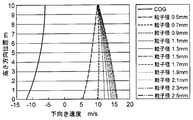
- FIG. 7 shows the velocity distributions of COG and liquid metal particles of various particle sizes under the same conditions.
- the vertical axis indicates the height direction position of the heat exchange tower 2, and the horizontal axis indicates the downward speed.
- tin having a small particle diameter for example, having a particle diameter of 0.5 mm, is ejected from the spray mist nozzle 3 at an initial speed of 10 m / s. It falls while being decelerated to about 5m / s.
- the particle diameter is 2.5 mm, the gravity is higher than the fluid drag, and it falls while accelerating.
- Cocurrent coke oven gas sensible heat recovery device 20 (hereinafter abbreviated as a cocurrent sensible heat recovery device) 20 shown in FIG.
- the exchange tower 2 and the heat medium recovery tank 5 are integrated.
- FIG. 8 the same constituent elements as those in FIG.
- the 800 ° C. COG is introduced into the heat exchange tower 22 from the top 22 a of the heat exchange tower 22 via the COG supply line 21, and is drawn out from the tower lower portion 22 b of the heat exchange tower 2 through the connecting pipe 18. ing.
- the COG supply line 21 and the connecting pipe 18 function as a second gas supply / exhaust path for supplying COG from the tower top 22 a of the heat exchange tower 22 and drawing it from the tower lower part 22 b of the heat exchange tower 22.
- the tar-attached tin droplets falling in the heat exchange tower 22 are received by a heat medium recovery tank 23 as a specific gravity separation tank provided in the lower part of the heat exchange tower 22, while the COG is cooled to about 320 ° C. It is sent out from the tower lower part 22b to the water sprinkler 11.
- the heat exchange tower 22 has a diameter of 3.6 m and a height H of 20 m.
- the droplet slowly falls due to the drag of the upward flowing COG, and the contact time with the droplet can be increased.
- the heat exchange efficiency is lower than that in the countercurrent direct contact heat exchange. Therefore, in the cocurrent sensible heat recovery apparatus 20, the height of the heat exchange tower 22 is increased to compensate for the decrease in heat exchange efficiency.
- a passage portion for taking out a part of the heat medium (tin droplets) condensed with tar is not provided, and all of the heat medium is removed. It is made to pour into the heat medium recovery tank 23 provided in the lower part of the heat exchange tower 22. Thereby, the spear 4, the first scissor pump 6, and the second spray nozzle 7 can be omitted, and the apparatus can be simplified.
- reference numeral 24 denotes a pressure equalizing tube.
- FIG. 9 is a graph showing the performance prediction calculation result of the heat exchange tower by the cocurrent sensible heat recovery device.
- the horizontal axis is the metal / gas mass flow ratio indicating the ratio of tin and coke oven gas supplied to the heat exchange tower 22, and the left vertical axis is the recovered heat / input power ratio and the liquid metal bath temperature ° C.
- the temperature of tin stored in the heat medium recovery tank 23 is shown, and the right vertical axis shows the heat exchange efficiency%.
- the heat medium amount flow rate is 125 times the COG mass flow rate because of cocurrent flow contact. Therefore, only 24 times heat recovery can be performed with respect to the power of the pump and the blower supplied to the cocurrent flow sensible heat recovery device 20.
- the cocurrent sensible heat recovery device 20 requires about eight times the power of the countercurrent sensible heat recovery device 1.
- the pump power is primarily larger than the blower power, and the pump power P (W) is proportional to mdot ⁇ H,
- m dot is the heat medium flow rate (kg / s)
- g is the acceleration of gravity (m / s 2 )
- H is the head (heat exchange tower height) (m)
- ⁇ is the pump efficiency.
- the parallel flow sensible heat recovery device 20 has an advantage that the facilities and the operation method can be greatly simplified.
- the operation of the first vertical pump 6 for the second spray mist nozzle 7 can be controlled so that the liquid level of the heat medium recovery tank 5 is maintained constant.
- the cocurrent flow sensible heat recovery device 20 such liquid level control is not required.
- the gutter 4 for taking out a part of the heat medium to the outside of the heat exchange tower 22 is not required, the passage portion 4b is not clogged and the maintenance is facilitated.
- COG has a sensible heat of about 800 ° C, so despite the amount of generated heat of about 0.95MJ / Nm 3 -COG, the tar condenses and adheres to the heat transfer tube when cooled to 450 ° C or below. So far, almost no heat recovery has been performed.
- tar is condensed on the surface of liquid tin by bringing tin droplets into direct contact with high-temperature COG, and then the specific gravity of tar and liquid tin is reduced. Since they are configured to be separated, if the present invention is applied to a coke oven, a significant cost reduction can be realized, and the amount of CO 2 emission can also be greatly reduced.
- the trap 4 is provided in the heat exchange tower 2 to receive the tin droplets with tar and supply it to the heat medium recovery tank 5.
- a heat medium recovery tank may be provided in the lower part of the heat exchange tower 2 without providing the tub 4. it can.
- the coke oven gas sensible heat recovery apparatus of the present invention can be used in the field of saving energy by recovering sensible heat of COG generated in a coke oven.
- Counter-current sensible heat recovery device Heat exchange tower (heat exchange device) 2a Tower lower part 2b Tower top part 3 Spattering mist nozzle (spraying nozzle) 4 ⁇ 4a Droplet receiving portion 4b Passage portion 4c Opening portion 4d Dive weir 5 Heat medium recovery tank 5a Discharge port 5b Shelf portion 6 First vertical pump 7 Second spray mist nozzle (second spray nozzle) 8 Second vertical pump 9 Boiler 10 Tar decanter 11 Aqueous water sprinkler 12 Pump 13 Circulation path 14 Conveyor 15 Second conveyor 16 Third chamber 17 Blower 18 Connection pipe 19 Discharge pipe 20 Cocurrent flow sensible heat recovery device 21 COG supply Line 22 Heat exchange tower 23 Heat medium recovery tank
Landscapes
- Chemical & Material Sciences (AREA)
- Engineering & Computer Science (AREA)
- Combustion & Propulsion (AREA)
- Chemical Kinetics & Catalysis (AREA)
- General Chemical & Material Sciences (AREA)
- Oil, Petroleum & Natural Gas (AREA)
- Organic Chemistry (AREA)
- Mechanical Engineering (AREA)
- General Engineering & Computer Science (AREA)
- Industrial Gases (AREA)
- Vaporization, Distillation, Condensation, Sublimation, And Cold Traps (AREA)
Abstract
Ce dispositif de récupération de la chaleur sensible d'un gaz de four à coke, qui peut effectuer une récupération de chaleur avec un rendement élevé à partir d'un gaz de four à coke, est caractérisé en ce qu'il comporte une colonne d'échange de chaleur (2), qui met le gaz de four à coke généré par le four à coke en contact direct avec un milieu thermique et qui condense le goudron sur la surface de ce milieu thermique, et un réservoir de récupération de véhicule thermique (5) qui est conçu pour recueillir le véhicule thermique auquel le goudron adhère, sépare le goudron du véhicule thermique par une séparation gravimétrique spécifique, et récupère le véhicule thermique.
Priority Applications (2)
| Application Number | Priority Date | Filing Date | Title |
|---|---|---|---|
| CN201280014682.0A CN103459556B (zh) | 2011-05-20 | 2012-04-27 | 炼焦炉气体显热回收装置 |
| KR1020137030374A KR101552416B1 (ko) | 2011-05-20 | 2012-04-27 | 코크스로 가스 현열 회수 장치 |
Applications Claiming Priority (2)
| Application Number | Priority Date | Filing Date | Title |
|---|---|---|---|
| JP2011-114027 | 2011-05-20 | ||
| JP2011114027 | 2011-05-20 |
Publications (1)
| Publication Number | Publication Date |
|---|---|
| WO2012160944A1 true WO2012160944A1 (fr) | 2012-11-29 |
Family
ID=47217027
Family Applications (1)
| Application Number | Title | Priority Date | Filing Date |
|---|---|---|---|
| PCT/JP2012/061315 Ceased WO2012160944A1 (fr) | 2011-05-20 | 2012-04-27 | Dispositif de récupération de la chaleur sensible d'un gaz de four à coke |
Country Status (4)
| Country | Link |
|---|---|
| JP (1) | JP5820328B2 (fr) |
| KR (1) | KR101552416B1 (fr) |
| CN (1) | CN103459556B (fr) |
| WO (1) | WO2012160944A1 (fr) |
Cited By (1)
| Publication number | Priority date | Publication date | Assignee | Title |
|---|---|---|---|---|
| CN114534313A (zh) * | 2022-03-03 | 2022-05-27 | 广东韶钢松山股份有限公司 | 一种焦油氨水分离槽顶部浮油消除方法 |
Citations (4)
| Publication number | Priority date | Publication date | Assignee | Title |
|---|---|---|---|---|
| JPS5311901A (en) * | 1976-07-16 | 1978-02-02 | Otto & Co Gmbh Dr C | Method and apparatus for cooling gas containing solids* tar and naphthalene |
| JPS57117591A (en) * | 1981-01-12 | 1982-07-22 | Sumitomo Metal Ind Ltd | Heat recovery from coke oven by-product gas |
| JPS6060182A (ja) * | 1983-09-13 | 1985-04-06 | Sumikin Coke Co Ltd | コ−クス炉ガス液の顕熱回収法 |
| JP2000093728A (ja) * | 1998-09-22 | 2000-04-04 | Ishikawajima Harima Heavy Ind Co Ltd | ガス精製方法及びその装置 |
Family Cites Families (1)
| Publication number | Priority date | Publication date | Assignee | Title |
|---|---|---|---|---|
| DE1751090A1 (de) * | 1968-04-02 | 1971-10-07 | Basf Ag | Verfahren zur Kuehlung von Spalt- oder Synthesegas und Waermeaustauscher zur Durchfuehrung des Verfahrens |
-
2012
- 2012-04-17 JP JP2012093669A patent/JP5820328B2/ja not_active Expired - Fee Related
- 2012-04-27 CN CN201280014682.0A patent/CN103459556B/zh not_active Expired - Fee Related
- 2012-04-27 KR KR1020137030374A patent/KR101552416B1/ko not_active Expired - Fee Related
- 2012-04-27 WO PCT/JP2012/061315 patent/WO2012160944A1/fr not_active Ceased
Patent Citations (4)
| Publication number | Priority date | Publication date | Assignee | Title |
|---|---|---|---|---|
| JPS5311901A (en) * | 1976-07-16 | 1978-02-02 | Otto & Co Gmbh Dr C | Method and apparatus for cooling gas containing solids* tar and naphthalene |
| JPS57117591A (en) * | 1981-01-12 | 1982-07-22 | Sumitomo Metal Ind Ltd | Heat recovery from coke oven by-product gas |
| JPS6060182A (ja) * | 1983-09-13 | 1985-04-06 | Sumikin Coke Co Ltd | コ−クス炉ガス液の顕熱回収法 |
| JP2000093728A (ja) * | 1998-09-22 | 2000-04-04 | Ishikawajima Harima Heavy Ind Co Ltd | ガス精製方法及びその装置 |
Cited By (1)
| Publication number | Priority date | Publication date | Assignee | Title |
|---|---|---|---|---|
| CN114534313A (zh) * | 2022-03-03 | 2022-05-27 | 广东韶钢松山股份有限公司 | 一种焦油氨水分离槽顶部浮油消除方法 |
Also Published As
| Publication number | Publication date |
|---|---|
| CN103459556B (zh) | 2015-02-04 |
| CN103459556A (zh) | 2013-12-18 |
| KR20140000350A (ko) | 2014-01-02 |
| JP5820328B2 (ja) | 2015-11-24 |
| KR101552416B1 (ko) | 2015-09-10 |
| JP2013007027A (ja) | 2013-01-10 |
Similar Documents
| Publication | Publication Date | Title |
|---|---|---|
| CN100569908C (zh) | 穹顶式除尘熄焦塔 | |
| US7156381B2 (en) | Heat recovery using fluidized spray tower | |
| EP1877522B1 (fr) | Procede de quench de gaz de synthèse | |
| CN103826737B (zh) | 多级循环流化床合成气冷却 | |
| JP5820328B2 (ja) | コークス炉ガス顕熱回収装置 | |
| CN108261883B (zh) | 含有氯硅烷的硅烷尾气处理方法 | |
| CN204981786U (zh) | 一种煤气除尘降温系统及煤气化系统 | |
| CN113462423B (zh) | 处理气相夹带的方法和放空系统 | |
| CN221638466U (zh) | 一种初冷器上段冷凝液固液分离喷洒装置 | |
| CN102559281B (zh) | 对气化骤冷室组件的水分移除 | |
| CN112774423A (zh) | 一种有机废气焚烧后烟气的净化处理工艺 | |
| CN201259384Y (zh) | 一种间接直接循环喷洒冷却气体捕集器 | |
| CN113265274B (zh) | 一种节能防堵的煤气洗涤方法 | |
| CN111712676A (zh) | 具有加压传热流体系统的太阳能接收器设备 | |
| CN105289179A (zh) | 一种低阻强制水冷滴型管式除雾器及除雾方法 | |
| CN204311033U (zh) | 多级的原始气体洗涤系统 | |
| CN106839808B (zh) | 荒煤气余热高低温综合回收系统及方法 | |
| CN114622056B (zh) | 转炉烟气激冷器、降温装置及提高降温效率的方法 | |
| CN107537266A (zh) | 一种高温热解气体的除尘系统及除尘方法 | |
| CN201043166Y (zh) | 穹顶式除尘熄焦塔 | |
| CN203768319U (zh) | 一种煤气余热回收利用装置 | |
| CN105419842B (zh) | 废塑料熔盐二次加热裂解塔 | |
| CN222503796U (zh) | 一种锅炉炉水排放处理装置 | |
| CN220558857U (zh) | 一种升华硫粉尘过滤回收装置 | |
| JPH0826330B2 (ja) | 連続式コークス製造設備における炉頂ガスダクトの閉塞防止設備 |
Legal Events
| Date | Code | Title | Description |
|---|---|---|---|
| 121 | Ep: the epo has been informed by wipo that ep was designated in this application |
Ref document number: 12789838 Country of ref document: EP Kind code of ref document: A1 |
|
| ENP | Entry into the national phase |
Ref document number: 20137030374 Country of ref document: KR Kind code of ref document: A |
|
| NENP | Non-entry into the national phase |
Ref country code: DE |
|
| 122 | Ep: pct application non-entry in european phase |
Ref document number: 12789838 Country of ref document: EP Kind code of ref document: A1 |