WO2012161021A1 - Endoscope - Google Patents
Endoscope Download PDFInfo
- Publication number
- WO2012161021A1 WO2012161021A1 PCT/JP2012/062322 JP2012062322W WO2012161021A1 WO 2012161021 A1 WO2012161021 A1 WO 2012161021A1 JP 2012062322 W JP2012062322 W JP 2012062322W WO 2012161021 A1 WO2012161021 A1 WO 2012161021A1
- Authority
- WO
- WIPO (PCT)
- Prior art keywords
- bending
- shape switching
- guide pipe
- built
- curved shape
- Prior art date
- Legal status (The legal status is an assumption and is not a legal conclusion. Google has not performed a legal analysis and makes no representation as to the accuracy of the status listed.)
- Ceased
Links
Images


Classifications
-
- A—HUMAN NECESSITIES
- A61—MEDICAL OR VETERINARY SCIENCE; HYGIENE
- A61B—DIAGNOSIS; SURGERY; IDENTIFICATION
- A61B1/00—Instruments for performing medical examinations of the interior of cavities or tubes of the body by visual or photographical inspection, e.g. endoscopes; Illuminating arrangements therefor
- A61B1/005—Flexible endoscopes
- A61B1/008—Articulations
-
- A—HUMAN NECESSITIES
- A61—MEDICAL OR VETERINARY SCIENCE; HYGIENE
- A61B—DIAGNOSIS; SURGERY; IDENTIFICATION
- A61B1/00—Instruments for performing medical examinations of the interior of cavities or tubes of the body by visual or photographical inspection, e.g. endoscopes; Illuminating arrangements therefor
- A61B1/00064—Constructional details of the endoscope body
- A61B1/00071—Insertion part of the endoscope body
- A61B1/0008—Insertion part of the endoscope body characterised by distal tip features
- A61B1/00096—Optical elements
-
- A—HUMAN NECESSITIES
- A61—MEDICAL OR VETERINARY SCIENCE; HYGIENE
- A61B—DIAGNOSIS; SURGERY; IDENTIFICATION
- A61B1/00—Instruments for performing medical examinations of the interior of cavities or tubes of the body by visual or photographical inspection, e.g. endoscopes; Illuminating arrangements therefor
- A61B1/00112—Connection or coupling means
- A61B1/00114—Electrical cables in or with an endoscope
-
- A—HUMAN NECESSITIES
- A61—MEDICAL OR VETERINARY SCIENCE; HYGIENE
- A61B—DIAGNOSIS; SURGERY; IDENTIFICATION
- A61B1/00—Instruments for performing medical examinations of the interior of cavities or tubes of the body by visual or photographical inspection, e.g. endoscopes; Illuminating arrangements therefor
- A61B1/005—Flexible endoscopes
- A61B1/0051—Flexible endoscopes with controlled bending of insertion part
- A61B1/0052—Constructional details of control elements, e.g. handles
-
- A—HUMAN NECESSITIES
- A61—MEDICAL OR VETERINARY SCIENCE; HYGIENE
- A61B—DIAGNOSIS; SURGERY; IDENTIFICATION
- A61B1/00—Instruments for performing medical examinations of the interior of cavities or tubes of the body by visual or photographical inspection, e.g. endoscopes; Illuminating arrangements therefor
- A61B1/005—Flexible endoscopes
- A61B1/0051—Flexible endoscopes with controlled bending of insertion part
- A61B1/0055—Constructional details of insertion parts, e.g. vertebral elements
-
- A—HUMAN NECESSITIES
- A61—MEDICAL OR VETERINARY SCIENCE; HYGIENE
- A61B—DIAGNOSIS; SURGERY; IDENTIFICATION
- A61B1/00—Instruments for performing medical examinations of the interior of cavities or tubes of the body by visual or photographical inspection, e.g. endoscopes; Illuminating arrangements therefor
- A61B1/005—Flexible endoscopes
- A61B1/0051—Flexible endoscopes with controlled bending of insertion part
- A61B1/0057—Constructional details of force transmission elements, e.g. control wires
-
- A—HUMAN NECESSITIES
- A61—MEDICAL OR VETERINARY SCIENCE; HYGIENE
- A61B—DIAGNOSIS; SURGERY; IDENTIFICATION
- A61B1/00—Instruments for performing medical examinations of the interior of cavities or tubes of the body by visual or photographical inspection, e.g. endoscopes; Illuminating arrangements therefor
- A61B1/005—Flexible endoscopes
- A61B1/01—Guiding arrangements therefore
-
- A—HUMAN NECESSITIES
- A61—MEDICAL OR VETERINARY SCIENCE; HYGIENE
- A61B—DIAGNOSIS; SURGERY; IDENTIFICATION
- A61B1/00—Instruments for performing medical examinations of the interior of cavities or tubes of the body by visual or photographical inspection, e.g. endoscopes; Illuminating arrangements therefor
- A61B1/012—Instruments for performing medical examinations of the interior of cavities or tubes of the body by visual or photographical inspection, e.g. endoscopes; Illuminating arrangements therefor characterised by internal passages or accessories therefor
- A61B1/018—Instruments for performing medical examinations of the interior of cavities or tubes of the body by visual or photographical inspection, e.g. endoscopes; Illuminating arrangements therefor characterised by internal passages or accessories therefor for receiving instruments
-
- A—HUMAN NECESSITIES
- A61—MEDICAL OR VETERINARY SCIENCE; HYGIENE
- A61B—DIAGNOSIS; SURGERY; IDENTIFICATION
- A61B1/00—Instruments for performing medical examinations of the interior of cavities or tubes of the body by visual or photographical inspection, e.g. endoscopes; Illuminating arrangements therefor
- A61B1/04—Instruments for performing medical examinations of the interior of cavities or tubes of the body by visual or photographical inspection, e.g. endoscopes; Illuminating arrangements therefor combined with photographic or television appliances
- A61B1/05—Instruments for performing medical examinations of the interior of cavities or tubes of the body by visual or photographical inspection, e.g. endoscopes; Illuminating arrangements therefor combined with photographic or television appliances characterised by the image sensor, e.g. camera, being in the distal end portion
-
- A—HUMAN NECESSITIES
- A61—MEDICAL OR VETERINARY SCIENCE; HYGIENE
- A61B—DIAGNOSIS; SURGERY; IDENTIFICATION
- A61B1/00—Instruments for performing medical examinations of the interior of cavities or tubes of the body by visual or photographical inspection, e.g. endoscopes; Illuminating arrangements therefor
- A61B1/06—Instruments for performing medical examinations of the interior of cavities or tubes of the body by visual or photographical inspection, e.g. endoscopes; Illuminating arrangements therefor with illuminating arrangements
- A61B1/0661—Endoscope light sources
- A61B1/0676—Endoscope light sources at distal tip of an endoscope
-
- A—HUMAN NECESSITIES
- A61—MEDICAL OR VETERINARY SCIENCE; HYGIENE
- A61B—DIAGNOSIS; SURGERY; IDENTIFICATION
- A61B1/00—Instruments for performing medical examinations of the interior of cavities or tubes of the body by visual or photographical inspection, e.g. endoscopes; Illuminating arrangements therefor
- A61B1/06—Instruments for performing medical examinations of the interior of cavities or tubes of the body by visual or photographical inspection, e.g. endoscopes; Illuminating arrangements therefor with illuminating arrangements
- A61B1/07—Instruments for performing medical examinations of the interior of cavities or tubes of the body by visual or photographical inspection, e.g. endoscopes; Illuminating arrangements therefor with illuminating arrangements using light-conductive means, e.g. optical fibres
-
- A—HUMAN NECESSITIES
- A61—MEDICAL OR VETERINARY SCIENCE; HYGIENE
- A61B—DIAGNOSIS; SURGERY; IDENTIFICATION
- A61B1/00—Instruments for performing medical examinations of the interior of cavities or tubes of the body by visual or photographical inspection, e.g. endoscopes; Illuminating arrangements therefor
- A61B1/12—Instruments for performing medical examinations of the interior of cavities or tubes of the body by visual or photographical inspection, e.g. endoscopes; Illuminating arrangements therefor with cooling or rinsing arrangements
-
- A—HUMAN NECESSITIES
- A61—MEDICAL OR VETERINARY SCIENCE; HYGIENE
- A61B—DIAGNOSIS; SURGERY; IDENTIFICATION
- A61B17/00—Surgical instruments, devices or methods
- A61B17/28—Surgical forceps
- A61B17/29—Forceps for use in minimally invasive surgery
-
- A—HUMAN NECESSITIES
- A61—MEDICAL OR VETERINARY SCIENCE; HYGIENE
- A61B—DIAGNOSIS; SURGERY; IDENTIFICATION
- A61B18/00—Surgical instruments, devices or methods for transferring non-mechanical forms of energy to or from the body
- A61B18/04—Surgical instruments, devices or methods for transferring non-mechanical forms of energy to or from the body by heating
- A61B18/12—Surgical instruments, devices or methods for transferring non-mechanical forms of energy to or from the body by heating by passing a current through the tissue to be heated, e.g. high-frequency current
-
- G—PHYSICS
- G02—OPTICS
- G02B—OPTICAL ELEMENTS, SYSTEMS OR APPARATUS
- G02B23/00—Telescopes, e.g. binoculars; Periscopes; Instruments for viewing the inside of hollow bodies; Viewfinders; Optical aiming or sighting devices
- G02B23/24—Instruments or systems for viewing the inside of hollow bodies, e.g. fibrescopes
- G02B23/2476—Non-optical details, e.g. housings, mountings, supports
Definitions
- the present invention relates to an endoscope having a bending portion whose bending radius can be changed on the distal end side of the insertion portion.
- endoscopes are widely used in the medical field and the industrial field. Endoscopes used in the medical field can observe the inside of the body by inserting the insertion portion into the body.
- endoscopes used in the industrial field can be inspected for the presence or absence of scratches or corrosion by inserting a soft and slender insertion part into a jet engine, a factory pipe or the like. It has become.
- various treatments can be performed by guiding a treatment tool into the body through a treatment tool insertion channel provided in the insertion portion.
- various repairs and the like can be performed by introducing a tool into the engine through an insertion channel provided in the insertion portion.
- Endoscopes having a soft and slender insertion part generally have a curved part on the distal end side of the insertion part.
- the bending portion is configured to bend in a plurality of directions according to a user's hand operation.
- the observation direction of the observation optical system provided at the distal end portion of the insertion portion can be changed to perform a wide range of examinations.
- an endoscope provided with a bending portion
- the bending portion is appropriately bent and the distal end portion is directed to the deep portion of the pipeline,
- the insertion part can be smoothly inserted toward the deep part of the pipeline.
- the bendable bending portion is arranged such that a plurality of bending pieces are arranged in the longitudinal axis direction, and the bending pieces are rotatably connected to each other so as to be bent in, for example, two directions of up and down, or four directions of up and down, left and right. It is mainly configured by providing a plurality of bending wires so as to correspond to the bending direction.
- the distal end of the bending wire is fixed at a predetermined position of the distal end bending piece located closest to the distal end among the bending pieces constituting the bending portion.
- the base end of each bending wire is fixed to a predetermined position of a pulley that is interlocked with a bending knob, for example, a bending operation device provided in the operation unit.
- the bending portion is bent with a predetermined bending radius (also referred to as curvature) starting from the bending portion proximal end in the longitudinal direction of the insertion portion.
- a bending portion configured by arranging a plurality of bending pieces is set to be bent at a predetermined bending radius starting from the bending portion proximal end side.
- the bending radius of the predetermined bending portion is smaller than the bending radius of the bending portion of the conduit, after bending the bending portion, even if trying to push the insertion portion in the direction in which the tip portion is facing, The insertion force is not transmitted in the target traveling direction, and there is a possibility that the insertion toward the deep part of the insertion part may be difficult.
- the bending radius of the predetermined bending portion is larger than the space of the observation site, the tip portion etc. will come into contact with the wall etc. May not be able to be performed.
- the user can selectively switch the bending radius by the user's own hand operation in consideration of the bending radius of the bent part of the pipe line or the size of the space of the examination site.
- An endoscope having a curved portion is desired.
- Japanese Patent Application Laid-Open No. 2002-345742 (hereinafter referred to as Document 1) describes an operability of a flexible adjustment mechanism in an endoscope of a type that adjusts the flexibility of a flexible tube portion by changing the bending rigidity of a coil.
- a flexible variable endoscope that improves durability is shown.
- the flexible variable endoscope includes a wire operation mechanism shown in FIG.
- the wire operating mechanism includes a coil in the flexible tube portion that is substantially concentric with the flexible tube portion, and a plurality of coil pulling wires that are engaged with the coil at different positions in the circumferential direction of the coil. The coil pulling wire is pulled or relaxed to expand and contract the coil.
- the flexible adjustment knob is operated to pull the coil pulling wire to compress the coil, so that the flexible tube portion is not easily bent (soft) but difficult to bend (hard). Can be adjusted.
- the flexible variable endoscope of Document 1 since the coil is arranged in the insertion portion, the internal space through which the internal part of the insertion portion is inserted is reduced by the amount of the arrangement of the coil. As a result, there is a risk of hindering the diameter reduction of the insertion portion.
- the coil pulling wire disposed on the inner peripheral surface of the coil shown in FIG. 2 is a wire for pulling the coil, and does not change the hardness of the insertion portion by the wire itself.
- the present invention has been made in view of the above circumstances, has a simple structure, and reliably bends the bending portion in all the four bending directions of the bending portion without reducing the space in the insertion portion.
- An object of the present invention is to provide an endoscope capable of selectively switching the radius.
- An endoscope includes an observation optical system at a distal end portion disposed at a distal end, and has a first direction, a second direction, a third direction, and a fourth direction on a proximal end side of the distal end portion.
- a bending portion configured to bend in four directions; and an insertion portion configured by connecting a flexible and flexible flexible tube portion on the proximal end side of the bending portion.
- a first bending portion that bends, and a plurality of bending pieces that are connected to the proximal end side of the first bending portion and that constitute the proximal end side of the bending portion are rotatably connected to the four directions.
- the flexible tube portion includes an inner peripheral surface of the flexible tube portion and corresponding to four directions that are the bending directions of the bend portion.
- the bending portion is fixed to a bending portion operating device provided at an operating portion arranged at a distal end fixed to the distal end of the first bending portion and having a proximal end connected to the proximal end side of the insertion portion.
- first guide pipes through which four bending wires corresponding to the bending direction of each of the first and second bending wires are inserted so as to freely advance and retract, and a distal end disposed at a predetermined position on the inner peripheral surface of the flexible tube portion Are fixed to the distal end of the second curved portion, and three curved shape switching wires whose base ends are fixed to the curved portion curved shape switching device provided in the operation portion are inserted through the three curved shape switching wires, respectively.
- the built-in object having the largest outer diameter is a position that contacts the adjacent first guide pipe, and two of the three guide pipes The circumferential position of the second guide pipe is the outermost diameter.
- the first guide pipe adjacent to the built-in object having a diameter is in a position in contact with the side opposite to the side in contact with the built-in object having the largest outer diameter, and the remaining one of the three guide pipes
- the circumferential position of one second guide pipe is at a position facing the built-in object having the largest outer diameter.
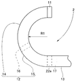
- FIG. 1 is a diagram for explaining an endoscope.
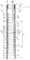
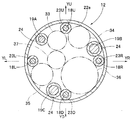
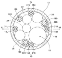
- Longitudinal section of the insertion portion for explaining the bending wire and the bending shape switching wire inserted into the insertion portion of the endoscope Y3-Y3 line cross-sectional view of FIG. Y4-Y4 cross-sectional view of FIG. Sectional view taken along line Y5-Y5 in FIG.
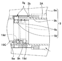
- the figure explaining the curved part curved with the pulling of the bending wire in the bending shape switching wire non-traction state The figure explaining the structure of the bending part curve shape switching apparatus provided in the operation part.
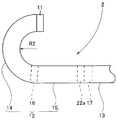
- the figure explaining the curved part curved with the pulling of the bending wire in the bending shape switching wire pulling state FIGS.
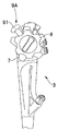
- FIG. 9 to 11 are diagrams for explaining another configuration of the bending portion bending shape switching device, and FIG. 9 is a view for explaining an operation portion having a lever for pulling the bending shape switching wire.
- the endoscope 1 includes an insertion portion 2, an operation portion 3, and a universal cord 4.
- the universal cord 4 is extended from the side part of the operation part 3, and the connector 5 is provided in the extension end.
- the connector 5 is electrically connected to an external device such as a control device and a lighting device.
- the operation section 3 is mainly provided with a bending portion operation device 6 and a bending portion bending shape switching device (hereinafter abbreviated as a bending shape switching device) 9.
- the curved shape switching device 9 includes an operation ring 9 a that rotates about the axis of the insertion portion 2.
- the bending portion operating device 6 is a device for performing an operation of bending the bending portion (see reference numeral 12 described later) of the insertion portion 2.
- the bending portion operating device 6 includes an up / down bending operation knob (hereinafter abbreviated as an up / down knob) 7 and a left / right bending operation knob (hereinafter abbreviated as a left / right knob) 8.
- the up / down knob 7 and the left / right knob 8 are rotatable around an axis (not shown), and are configured to rotate clockwise or counterclockwise in FIG.
- the insertion portion 2 is configured by connecting a distal end portion 11, a bending portion 12, and a flexible tube portion 13 in order from the distal end side.
- the operation unit 3 is connected to the proximal end side of the insertion unit 2.
- the distal end portion 11 is provided with an observation optical system.
- the observation optical system includes an illumination unit (not shown) that illuminates the observation site and an imaging unit (not shown) that images the observation site illuminated by the illumination unit.
- the bending portion 12 includes a first bending portion 14, a second bending portion 15, and a connecting piece 16. That is, the bending portion 12 is divided into a first bending portion 14 and a second bending portion 15.
- the first bending portion 14 constitutes the distal end side of the bending portion 12.
- the second bending portion 15 is connected to the proximal end side of the first bending portion 14 and constitutes the proximal end side of the bending portion 12.
- the first bending portion 14 is configured to bend in four directions, up, down, left, and right by connecting a plurality of bending pieces 21 and the like in a freely rotatable manner.
- the second bending portion 15 is configured to bend in four directions, up, down, left and right, by connecting a plurality of bending pieces 22 and the like in a freely rotatable manner.
- the bending piece 21 constituting the first bending portion 14 and the bending piece 22 constituting the second bending portion 15 may have the same configuration or different configurations.
- the first bending portion 14 is configured to bend in four directions, up, down, left, and right by rotatably connecting the tip bending piece 21f, the plurality of bending pieces 21, and the connecting piece 16.
- the tip bending piece 21f constitutes the tip of the bending portion 12 and the tip of the first bending portion.
- the connecting piece 16 constitutes the first curved portion proximal end.
- the second bending portion 15 has a configuration in which the connecting piece 16, the plurality of bending pieces 22, and the base end bending piece 22e are rotatably connected to bend in four directions, up, down, left, and right.
- the connecting piece 16 constitutes the distal end of the second curved portion.
- the proximal end bending piece 22e constitutes the most proximal end of the bending portion 12 and the second curved portion proximal end.
- the connecting piece 16 serves as both the proximal bending piece of the first bending portion 14 and the distal bending piece of the second bending portion 15.
- the flexible tube portion 13 is soft and flexible.
- the proximal bending piece 22e is connected to a connection base 17 fixed on the distal end side of the flexible tube portion 13.
- a treatment instrument channel As shown in FIGS. 2 to 5, in the insertion portion 2, four bending wires 18 that bend the bending portion 12 in four directions, up and down, left and right, three bending shape switching wires 19 to be described later, and an imaging cable 33.
- the four bending wires 18 are respectively inserted into four first guide pipes 31 described later so as to freely advance and retract.
- the four first guide pipes 31 respectively correspond to the bending direction.
- the three curved shape switching wires 19 are inserted into three second guide pipes 32, which will be described later, so as to freely advance and retract.
- the imaging cable 33, the light guides 34 and 35, the treatment instrument channel 36, and the air / water supply tube 37 are not shown in order to simplify the drawing.
- the four bending wires 18 illustrate two bending wires 18, and the three bending shape switching wires 19 illustrate one bending shape switching wire.
- the imaging cable 33, the light guides 34 and 35, the treatment instrument channel 36, and the air / water supply tube 37 are built-in objects that are inserted through the insertion portion 2, and are indicated by two-dot chain lines.
- the treatment instrument channel 36 is a conduit for introducing a treatment instrument such as a grasping forceps or an electric knife into the body, for example.
- the treatment instrument channel 36 is desired to have a large inner diameter.
- the treatment instrument channel 36 is a built-in object having the largest outer diameter.
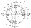
- the four first guide pipes 31 are positions corresponding to the four bending directions of the bending portion 12, and are predetermined positions on the inner peripheral surface of the flexible tube portion 13. It is arranged. Specifically, the four first guide pipes 31 are provided on the inner peripheral surface of the flexible tube portion 13 at a predetermined interval in the circumferential direction, for example, at equal intervals.
- the distal ends of the four first guide pipes 31 are fixed at predetermined positions of the connection cap 17, and the respective proximal ends are fixed at predetermined positions (not shown) in the operation unit 3. .
- Each bending wire 18 is inserted into the first guide pipe 31.
- Each distal end of the bending wire 18 extends from the distal end opening of the first guide pipe 31 into the bending portion 12, and is fixed to a predetermined position of the distal bending piece 21f by, for example, brazing.
- the distal ends of the bending wires 18 are fixed at positions corresponding to the upper, lower, left, and right, which are the four bending directions of the bending portion 12.
- each base end of the bending wire 18 extends from the base end opening of the first guide pipe 31 into the operation unit 3, and a predetermined position of an upper and lower pulley (not shown) constituting the bending unit operation device 6, and The left and right pulleys (not shown) are fixed at predetermined positions.
- the upper and lower pulleys are configured integrally with the upper and lower knobs 7, and the left and right pulleys are configured integrally with the left and right knobs 8.
- the arrow YU direction indicates a first direction (upward direction) that is one of the bending directions of the bending portion 12, and the arrow YD direction is a direction opposite to the upward direction and indicates the bending portion.
- the arrow YL direction indicates a third direction (left direction) that is one of the bending directions of the bending portion 12, and the arrow YR direction is the direction opposite to the left direction and is the bending portion.
- reference numeral 31U indicates an upper first guide pipe
- reference numeral 31D indicates a lower first guide pipe
- reference numeral 31L indicates a left first guide pipe
- reference numeral 31R indicates a right first guide pipe.
- Reference numeral 18U represents an upward bending wire
- reference numeral 18D represents a downward bending wire
- reference numeral 18L represents a left bending wire
- reference numeral 18R represents a right bending wire.
- symbol 23 in FIG. 2 is a curved wire receptacle.
- the bending wire receiver 23 has predetermined inner surfaces of the bending pieces 21 and 22 for the purpose of defining the circumferential position and the radial position of the bending wires 18U, 18D, 18L, and 18R in the bending portion 12. It is fixed in position.
- the bending portion 12 of the endoscope 1 is preliminarily configured as shown in FIG. 6 when, for example, the upward bending wire 18U is pulled by the operation of the up / down knob 7 in a non-traction state of a bending shape switching wire described later. It bends upward with a defined radius of curvature R1. In this curved state, the downward bending wire 18D is in a relaxed state. The bending portion 12 is bent starting from a proximal bending piece 22e that constitutes the most proximal end.
- the bending portion 12 of the endoscope 1 has a bending radius R1 starting from the proximal bending piece 22e when, for example, the left bending wire 18L is pulled by operating the left and right knobs 8 when the bending shape switching wire is not pulled. To the left. In this curved state, the right-direction bending wire 18R is in a relaxed state. Conversely, when the right bending wire 18R is pulled by operating the left and right knob 8, the bending portion 12 bends to the right with the bending radius R1 starting from the proximal bending piece 22e. In this curved state, the left-direction bending wire 18L is in a relaxed state.
- the bending portion 12 is integrated with the second bending portion 15 and the first bending portion 14 included in the bending portion 12 in accordance with the operation of the up / down knob 7 or the left / right knob 8. To bend in any direction of up, down, left and right.
- the three second guide pipes 32 are arranged on the inner peripheral surface of the flexible tube portion 13 in consideration of the insertion positions of a plurality of built-in objects inserted into the insertion portion 2. . Specifically, the arrangement positions in the circumferential direction of the three second guide pipes 32 are determined based on the arrangement position of the treatment instrument channel 36 having the largest outer diameter among the built-in objects.
- two of the three second guide pipes 32 are arranged to form the widest maximum built-in object insertion space 2S for arranging the treatment instrument channel 36 in the insertion portion 2. That is, the second guide pipe 32 which is one of the two second guide pipes 32 is on the YU side of the right first guide pipe 31R and abuts on the outer peripheral surface of the right first guide pipe 31R. Be placed. On the other hand, the second guide pipe 32, which is the other of the second guide pipes 32, is arranged on the YL side of the lower first guide pipe 31D and in contact with the outer peripheral surface of the lower first guide pipe 31D. . As a result, a maximum built-in object insertion space 2S for arranging the treatment instrument channel 36 is formed between the right first guide pipe 31R and the lower first guide pipe 31D.
- the remaining one of the three second guide pipes 32 is disposed inside the left first guide pipe 31L and the upper first guide pipe 31U. Specifically, the remaining one second guide pipe 32 is arranged at a position facing the treatment instrument channel 36 arranged between the right first guide pipe 31R and the lower first guide pipe 31D.
- Each distal end of each of the three second guide pipes 32 is fixed at a predetermined position of the connection base 17, and each base end is fixed at a predetermined position (not shown) in the operation unit 3.
- Each curved shape switching wire 19 is inserted into the second guide pipe 32.
- Each distal end of the curved shape switching wire 19 extends from the distal end opening of the second guide pipe 32 into the curved portion 12 and is fixed to a predetermined position of the connecting piece 16 by, for example, brazing.
- the proximal end of each curved shape switching wire 19 extends from the proximal end of the second guide pipe 32 into the operation unit 3 and is fixed to a predetermined position of the curved shape switching device 9.
- the curved shape switching wires 19 inserted through the second guide pipes 32 have different tensile strengths. For this reason, in the present embodiment, reference numerals 19A, 19B, and 19C are assigned to distinguish the curved shape switching wires.
- the tensile strength of the curved shape switching wires 19B and 19C is set in advance stronger than the tensile strength of the curved shape switching wire 19A, and one curved shape switching wire 19B and one curved shape are set.
- the switching wire 19 ⁇ / b> C has a tensile strength that can maintain a cured state of the second curved portion 15 described later.
- the diameter dimensions are different. The diameters of the curved shape switching wires 19B and 19C are larger than the diameter of the curved shape switching wire 19A, and the tensile strength is set to be large.
- the three second guide pipes 32 are distinguished from each other by being provided with reference numerals 32A, 32B, and 32C, respectively. That is, the curved shape switching wire 19C is inserted through the second guide pipe 32C, the curved shape switching wire 19B is inserted through the second guide pipe 32B, and the curved shape switching wire 19A is inserted through the second guide pipe 32A.
- the tensile strength of the curved shape switching wire may be changed using curved shape switching wires having different Young's moduli without changing the wire diameter.
- the curved shape switching wire 19A is also set to have a predetermined tensile strength or more. Specifically, the cured state of the second curved portion 15 is held by the two curved shape switching wires 19A and 19C, and the cured state of the second curved portion 15 is held by the two curved shape switching wires 19A and 19B. Is the tensile strength at which
- the curved shape switching device 9 in which the proximal ends of the curved shape switching wires 19A, 19B, and 19C are arranged will be described.
- the curved shape switching device 9 mainly includes an operation ring 9a, a cam ring 9b, a moving ring 9c, and a cam pin 9d.
- a stopper 19d is fixed in advance to the base ends of the curved shape switching wires 19A, 19B, and 19C.
- FIG. 7 for simplification of the drawing, one of the three curved shape switching wires 19A, 19B, 19C is shown.
- the operation ring 9a is configured to rotate about the operation unit longitudinal axis at a predetermined position on the outer peripheral surface side of the operation unit tip 3A. That is, the operation ring 9a is configured to be gripped by the user and rotated clockwise or counterclockwise about the longitudinal axis.
- the cam ring 9b is disposed in the inner peripheral surface of the operation ring 9a, and is slidably disposed on the outer peripheral surface of the operation portion tip portion 3A.
- the cam ring 9b is configured to advance and retract the operation unit 3 in the longitudinal axis direction as the operation ring 9a rotates.
- a groove cam 9g having a predetermined shape is formed on the cam ring 9b.
- the moving ring 9c is arranged to slide in the operation unit 3. Specifically, the moving ring 9c is disposed on the inner peripheral surface side of the cam ring 9b so as to slide in the operation portion distal end portion 3A.
- a cam pin 9d protruding in the outer peripheral direction is fixed at a predetermined position of the moving ring 9c.
- the protruding end portion of the cam pin 9d passes through a long hole 3b formed in advance in the operation portion distal end portion 3A and is disposed in the groove cam 9g of the cam ring 9b.
- Numeral 9h is a stopper accommodating hole for accommodating the stopper 19d.
- the stopper accommodating hole 9h is formed at a predetermined position on the proximal end surface of the moving ring 9c for the purpose of defining the circumferential position of the proximal end portion of the curved shape switching wires 19A, 19B, 19C.
- Reference numeral 9w denotes an axial through hole through which a curved shape switching wire is inserted.
- the central axis of the stopper accommodating hole 9h and the central axis of the axial through hole 9w are coaxial.
- the cam ring 9b when the operation ring 9a is rotated in the clockwise direction, for example, the cam ring 9b is moved to the longitudinal base end side of the operation unit 3 along with the rotation.
- the cam pin 9d moves in the groove cam 9g, and as the pin 9d moves, the moving ring 9c moves toward the longitudinal base end side of the operation portion 3.
- the moving ring 9c is retracted from the position indicated by the solid line to the position indicated by the broken line.
- the stoppers 19d fixed to the base ends of the curved shape switching wires 19A, 19B, and 19C are simultaneously retracted as indicated by solid lines.
- the tensions of the curved shape switching wires 19A, 19B, 19C are increased simultaneously.
- the distal ends of the curved shape switching wires 19 ⁇ / b> A, 19 ⁇ / b> B, and 19 ⁇ / b> C are fixed to the connecting piece 16 that is the distal bending piece of the second bending portion 15.
- the tension of the wires 19A, 19B, and 19C is simultaneously increased and stretched.
- the plurality of bending pieces 22 constituting the second bending portion 15 are compressed in the insertion portion axial direction. As a result, the second bending portion 15 changes from a bendable state to a cured state.
- the first bending portion 14 constituting the bending portion 12 of the present embodiment is in a bendable state.
- the second bending portion 15 is cured by operating the bending shape switching device 9 of the endoscope 1, and for example, the upward bending wire 18 ⁇ / b> U is pulled by operating the up / down knob 7. Then, the first bending portion 14 of the bending portion 12 is bent upward from the connecting piece 16 constituting the most proximal end of the first bending portion 14.
- the bending shape switching wire 19 ⁇ / b> C is positioned substantially opposite to the upward bending wire 18 ⁇ / b> U, in other words, the bending shape switching wire 19 ⁇ / b> C and the upward bending wire 18 ⁇ / b> U are substantially points across the center point O.
- the upward bending wire 18U is disposed at a symmetric position, that is, a position displaced from the wire 19C by approximately 180 degrees with respect to the circumferential direction. According to this configuration, when the second bending portion 15 is in the cured state, the first bending portion 14 is arranged in the upper space of the insertion portion divided by the horizontal line H passing through the center point O when the first bending portion 14 is bent upward.
- the bending shape switching wire 19C disposed in the space below the insertion portion is more tensioned than the bending shape switching wires 19A and 19B.
- the tensile strength of the curved shape switching wire 19C is set so that the cured state of the second curved portion 15 can be maintained. Accordingly, the single bending shape switching wire 19 ⁇ / b> C maintains the cured state of the second bending portion 15, and only the first bending portion 14 is bent upward. As a result, as shown in FIG. 8, in the bending portion 12, the first bending portion 14 is bent upward at a predetermined bending radius R2 smaller than the bending radius R1.
- the first bending portion 14 is bent leftward from the connecting piece 16 with a bending radius R2.
- the bending shape switching wire 19B is disposed at a position substantially opposite to the left bending wire 18L. For this reason, when the first curved portion 14 is curved leftward, the curved shape switching wire 19A disposed in the insertion portion left space divided by the vertical line V perpendicular to the horizontal line H passing through the center point O, Greater tension is applied to the curved shape switching wire 19B arranged in the right space of the insertion portion than 19C.
- the tensile strength of the curved shape switching wire 19B is set so that the cured state of the second curved portion 15 can be maintained. Accordingly, one bending shape switching wire 19B maintains the cured state of the second bending portion 15, and only the first bending portion 14 is bent leftward. As a result, as shown in FIG. 8, in the bending portion 12, the first bending portion 14 is bent leftward with the bending radius R2.
- the first bending portion 14 starts from the connecting piece 16 and the bending radius R2 It will be bent downward.
- the first bending portion 14 starts from the connecting piece 16 to the right. It is curved in the direction.
- the lighting unit includes two light guides 34 and 35.
- the illumination unit is not limited to the two light guides 34 and 35, and may be one light guide or three or more light guides.
- the lighting unit is not limited to a light guide, and may be a light emitting element such as an LED. In the case of a light emitting element, an electric wire extending from the light emitting element is a built-in object.
- the treatment instrument channel 36 is disposed between the right first guide pipe 31R and the lower first guide pipe 31D.
- the arrangement position of the treatment instrument channel 36 is not limited between the right first guide pipe 31R and the lower first guide pipe 31D. That is, if the first guide pipes 31U, 31R, 31D, 31L are adjacent to each other between the adjacent first guide pipes, the lower first guide pipe 31D and the left first guide pipe 31L, or the left It may be between the direction first guide pipe 31L and the upper first guide pipe 31U, or between the upper first guide pipe 31U and the right first guide pipe 31R.
- the endoscope is not limited to the configuration including the treatment instrument channel 36 as a built-in object, and may be configured such that the treatment instrument insertion channel is unnecessary.
- the curved shape switching wire receiver 24 is provided in advance on the inner surface of each curved portion 22 for the purpose of defining the circumferential position and the radial position of each curved shape switching wire 19A, 19B, 19C in the second curved portion 15. It is provided at a fixed position.
- the positions of the curved shape switching wires 19A, 19B, and 19C may be defined by providing a string guide (see reference numeral 25 in FIG. 3) instead of the curved shape switching wire receiver 24.
- the diameter of the curved shape switching wire receiver 24 also corresponds to the diameter of the curved shape switching wires 19A, 19B, and 19C, as with the second guide pipe 32.
- symbol 26 in FIG. 2 is a braid
- the blade 26 covers the outer periphery of the first curved portion 14 and the outer periphery of the second curved portion 15.
- Reference numeral 27 is a curved rubber. The curved rubber 27 covers the outer periphery of the blade 26.
- the bending angle is generally set to be the largest and the bending performance in the bending upward direction with the highest bending operation frequency is reliably maintained over a long period of time. be able to.
- the tension of the bending shape switching wires 19A, 19B, and 19C is simultaneously reduced by rotating the operation ring 9a in the reverse direction.
- the second bending portion 15 returns from the cured state to the bendable state.
- the bending portion 12 of the endoscope 1 is divided into two parts by the first bending portion 14 and the second bending portion 15.
- the operation unit 3 of the endoscope 1 includes an upper / lower knob 7 for bending the bending portion 12 in the up / down direction, a left / right knob 8 for bending the bending portion in the left / right direction, and a second bending portion 15.
- a curved shape switching device 9 for changing to a cured state is provided.
- the tips of the four bending wires 18 corresponding to the up and down and left and right directions pulled and relaxed by the up and down knob 7 and the left and right knob 8 of the endoscope 1 are fixed to the tip bending piece 21f constituting the forefront of the bending portion 12, respectively. To do.
- first bending portion 14 and the second bending portion 15 are connected to the distal ends of the three bending shape switching wires 19 that are pulled and relaxed by the bending shape switching device 9 of the endoscope 1. It fixes to the connection piece 16 which comprises the most proximal end.
- the bending portion 12 is configured by operating the up / down knob 7 or the left / right knob 8 after curing the second bending portion 15 by operating the bending shape switching device 9. Only the first bending portion 14 to be bent can be bent with the bending radius R2 in either the upward direction or the downward direction, or in the left direction or the right direction.
- the up / down knob 7 or the left / right knob 8 without operating the bending shape switching device 9, that is, in a state where the second bending portion 15 can be bent, the first bending portion constituting the bending portion 12. 14 and the second curved portion 15 can be simultaneously bent in either the upward direction or the downward direction, or in the left direction or the right direction with a bending radius R1 larger than the bending radius R2.
- the user can consider the size of the space of the observation site in advance, and by selectively switching the bending radius of the bending portion to the bending radius R1 and the bending radius R2 by his / her hand operation, the best operability is achieved. Alternatively, the best observation performance can be obtained.
- the operator arranges the treatment instrument channel 36 which is the endoscope having the largest diameter dimension between the first guide pipes 31R and 31D, and the endoscope having the largest diameter.
- the imaging cable 33, the light guides 34 and 35, the air / water supply tube 37, and the like, which are a plurality of built-in objects having a smaller diameter, can be easily arranged in the insertion portion 2.
- the bending radius of the bending portion 12 can be selectively selected with respect to all the upper, lower, left and right bending directions of the bending portion 12 without increasing the diameter of the insertion portion 2 of the endoscope 1.
- the endoscope 1 which can be switched to the curvature radius R2 is realizable.
- FIG. 9 is a diagram showing a lever that pulls the curved shape switching wire provided in the operation portion
- FIG. 10 is a diagram illustrating a link mechanism provided in the operation portion that pulls the curved shape switching wire
- FIG. 11 is Y11 in FIG. This is a cross section taken along line -Y11.
- the operation ring 9a of the bending shape switching device 9 is rotated in the insertion portion axial direction, and the bending shape switching wires 19A, 19B, and 19C are pulled, and the second bending portion 15 is in a cured state.
- the configuration of the bending shape switching device that cures the second bending portion 15 is not limited to this configuration, and the vicinity of the upper and lower knobs 7 and 8 provided in the operation unit 3 as shown in FIG.
- a curved shape switching lever (hereinafter abbreviated as a lever) 91 may be provided.
- the lever 91 is rotated clockwise or counterclockwise about an axis to be described later to pull and loosen the curved shape switching wires 19A, 19B, 19C, and the second curved portion 15 is cured. It can be switched to a state or a bendable state.
- the curved shape switching device 9 ⁇ / b> A includes a lever 91 that rotates clockwise or counterclockwise with respect to the operation shaft 90.
- the base end of the link 92 is pivotally supported at a predetermined position of the lever 91.
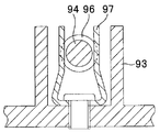
- the distal end of the link 92 is pivotally supported by the base end of an elongated rod 94 slidably disposed in the guide member 93.
- a locking member 95 is fixed to the tip of the rod 94.
- the locking member 95 is formed with an axial through hole 95w through which the curved shape switching wires 19A, 19B, and 19C are inserted.
- a stopper 19d is fixed to the base ends of the curved shape switching wires 19A, 19B, and 19C.
- FIG. 10 one of the three curved shape switching wires 19A, 19B, and 19C is shown to simplify the drawing.
- the convex part 96 is provided in the position previously spaced apart from the front-end
- the convex portion 96 is provided so as to protrude to the inner peripheral surface side on the distal end side of the guide member 93 when the lever 91 is rotated and the rod 94 is moved to the proximal end side by the link 92, for example.
- the spring 97 is fixed by a snap fit as shown by a two-dot chain line. As a result, the moving position of the rod 94 is fixed, and the curved shape switching wires 19A, 19B, 19C are held in the pulled state.
Landscapes
- Health & Medical Sciences (AREA)
- Life Sciences & Earth Sciences (AREA)
- Surgery (AREA)
- Physics & Mathematics (AREA)
- Engineering & Computer Science (AREA)
- Animal Behavior & Ethology (AREA)
- Nuclear Medicine, Radiotherapy & Molecular Imaging (AREA)
- Biomedical Technology (AREA)
- Heart & Thoracic Surgery (AREA)
- Medical Informatics (AREA)
- Molecular Biology (AREA)
- General Health & Medical Sciences (AREA)
- Public Health (AREA)
- Veterinary Medicine (AREA)
- Optics & Photonics (AREA)
- Radiology & Medical Imaging (AREA)
- Pathology (AREA)
- Biophysics (AREA)
- Ophthalmology & Optometry (AREA)
- Otolaryngology (AREA)
- Plasma & Fusion (AREA)
- Rehabilitation Therapy (AREA)
- Astronomy & Astrophysics (AREA)
- General Physics & Mathematics (AREA)
- Instruments For Viewing The Inside Of Hollow Bodies (AREA)
- Endoscopes (AREA)
Abstract
La présente invention concerne un endoscope comportant une première partie courbe configurant le côté terminal d'une section courbe, et une seconde partie courbe formée de façon continue avec le côté base de la première partie courbe. Dans une section de tube flexible, sont placés quatre premiers tubes de guidage qui sont disposés sur la surface interne de la section de tube flexible et à travers lesquels sont insérés de manière rétractable quatre câbles de flexion fixés, au niveau des extrémités, de la première partie courbe ; et trois seconds tubes de guidage à travers lesquels sont insérés de manière rétractable trois câbles d'aiguillage de forme courbe fixés, au niveau des extrémités, à l'extrémité de la seconde partie courbe. L'élément intégré ayant le plus grand diamètre extérieur est dans une position de contact avec le premier tube de guidage adjacent. La position d'arrangement dans la direction de circonférence de deux des trois tubes de guidage est en contact avec le côté opposé à l'emplacement où ledit premier tube de guidage adjacent à l'élément intégré ayant le plus grand diamètre extérieur touche ledit élément intégré ayant le plus grand diamètre extérieur, et la position dans la direction de circonférence du second tube de guidage restant se situe opposé audit élément intégré ayant le plus grand diamètre.
Priority Applications (2)
| Application Number | Priority Date | Filing Date | Title |
|---|---|---|---|
| JP2012552603A JP5253676B2 (ja) | 2011-05-20 | 2012-05-14 | 内視鏡 |
| US13/682,355 US9173552B2 (en) | 2011-05-20 | 2012-11-20 | Endoscope |
Applications Claiming Priority (2)
| Application Number | Priority Date | Filing Date | Title |
|---|---|---|---|
| JP2011113903 | 2011-05-20 | ||
| JP2011-113903 | 2011-05-20 |
Related Child Applications (1)
| Application Number | Title | Priority Date | Filing Date |
|---|---|---|---|
| US13/682,355 Continuation US9173552B2 (en) | 2011-05-20 | 2012-11-20 | Endoscope |
Publications (1)
| Publication Number | Publication Date |
|---|---|
| WO2012161021A1 true WO2012161021A1 (fr) | 2012-11-29 |
Family
ID=47217101
Family Applications (1)
| Application Number | Title | Priority Date | Filing Date |
|---|---|---|---|
| PCT/JP2012/062322 Ceased WO2012161021A1 (fr) | 2011-05-20 | 2012-05-14 | Endoscope |
Country Status (3)
| Country | Link |
|---|---|
| US (1) | US9173552B2 (fr) |
| JP (1) | JP5253676B2 (fr) |
| WO (1) | WO2012161021A1 (fr) |
Cited By (2)
| Publication number | Priority date | Publication date | Assignee | Title |
|---|---|---|---|---|
| CN115397302A (zh) * | 2020-03-30 | 2022-11-25 | 奥林巴斯株式会社 | 内窥镜的弯曲部、内窥镜插入部、内窥镜 |
| JP2024523007A (ja) * | 2021-06-10 | 2024-06-25 | ボストン サイエンティフィック サイムド,インコーポレイテッド | 遠位関節可動セクションを有する医療デバイス |
Families Citing this family (12)
| Publication number | Priority date | Publication date | Assignee | Title |
|---|---|---|---|---|
| EP2598075A4 (fr) | 2010-07-28 | 2016-11-30 | Medrobotics Corp | Positionnement chirurgical et système de support |
| JP5080702B2 (ja) * | 2010-09-28 | 2012-11-21 | オリンパスメディカルシステムズ株式会社 | 内視鏡装置 |
| AU2011316849B2 (en) * | 2010-10-22 | 2016-05-26 | Medrobotics Corporation | Highly articulated robotic probes and methods of production and use of such probes |
| EP2637551B1 (fr) | 2010-11-11 | 2019-10-02 | Medrobotics Corporation | Dispositifs d'introduction de sondes robotiques très articulées |
| EP2755805B1 (fr) | 2011-09-13 | 2018-05-09 | Medrobotics Corporation | Sondes très articulées pourvues d'un dispositif d'articulation anti-torsion |
| WO2017006376A1 (fr) * | 2015-07-09 | 2017-01-12 | 川崎重工業株式会社 | Robot chirurgical |
| US11559190B2 (en) | 2017-05-03 | 2023-01-24 | Canon U.S.A., Inc. | Steerable medical device and method |
| WO2020008571A1 (fr) * | 2018-07-04 | 2020-01-09 | オリンパス株式会社 | Endoscope |
| CN115023170B (zh) | 2020-01-16 | 2026-04-10 | 奥林巴斯株式会社 | 内窥镜系统、控制装置以及信息处理方法 |
| EP4216795A1 (fr) | 2020-09-25 | 2023-08-02 | Boston Scientific Scimed, Inc. | Dispositif d'imagerie médicale |
| DE102020126239A1 (de) * | 2020-10-07 | 2022-04-07 | Hoya Corporation | Endoskop mit flexiblem Einführschlauch und Biegeabschnitt |
| CN112806949A (zh) * | 2021-02-01 | 2021-05-18 | 邢媛媛 | 一种可视化的多功能ercp插管导管及其插管方法 |
Citations (8)
| Publication number | Priority date | Publication date | Assignee | Title |
|---|---|---|---|---|
| JPH02118501U (fr) * | 1989-03-13 | 1990-09-25 | ||
| JPH0343802U (fr) * | 1989-09-07 | 1991-04-24 | ||
| JPH1014861A (ja) * | 1996-07-01 | 1998-01-20 | Olympus Optical Co Ltd | 内視鏡 |
| JPH1024013A (ja) * | 1996-07-12 | 1998-01-27 | Olympus Optical Co Ltd | 内視鏡 |
| JPH10201703A (ja) * | 1997-01-24 | 1998-08-04 | Olympus Optical Co Ltd | 内視鏡 |
| JP2002143084A (ja) * | 2000-11-06 | 2002-05-21 | Olympus Optical Co Ltd | 内視鏡装置 |
| JP2006068393A (ja) * | 2004-09-03 | 2006-03-16 | Olympus Corp | 内視鏡 |
| WO2011114570A1 (fr) * | 2010-03-15 | 2011-09-22 | オリンパスメディカルシステムズ株式会社 | Endoscope |
Family Cites Families (7)
| Publication number | Priority date | Publication date | Assignee | Title |
|---|---|---|---|---|
| JPH02118501A (ja) * | 1988-10-28 | 1990-05-02 | Hitachi Ltd | 投写形テレビ用レンズ |
| JPH0343802A (ja) * | 1989-07-12 | 1991-02-25 | Omron Corp | ファジィコントローラ |
| WO1993013704A1 (fr) * | 1992-01-09 | 1993-07-22 | Endomedix Corporation | Mini-endoscope bidirectionnel |
| JPH10328131A (ja) * | 1997-06-04 | 1998-12-15 | Olympus Optical Co Ltd | 内視鏡装置 |
| JP4855867B2 (ja) * | 2006-08-22 | 2012-01-18 | オリンパスメディカルシステムズ株式会社 | 内視鏡 |
| JP2009112537A (ja) * | 2007-11-07 | 2009-05-28 | Hoya Corp | 可撓性内視鏡 |
| JP5235773B2 (ja) * | 2009-04-30 | 2013-07-10 | Hoya株式会社 | 可撓性内視鏡 |
-
2012
- 2012-05-14 JP JP2012552603A patent/JP5253676B2/ja not_active Expired - Fee Related
- 2012-05-14 WO PCT/JP2012/062322 patent/WO2012161021A1/fr not_active Ceased
- 2012-11-20 US US13/682,355 patent/US9173552B2/en not_active Expired - Fee Related
Patent Citations (8)
| Publication number | Priority date | Publication date | Assignee | Title |
|---|---|---|---|---|
| JPH02118501U (fr) * | 1989-03-13 | 1990-09-25 | ||
| JPH0343802U (fr) * | 1989-09-07 | 1991-04-24 | ||
| JPH1014861A (ja) * | 1996-07-01 | 1998-01-20 | Olympus Optical Co Ltd | 内視鏡 |
| JPH1024013A (ja) * | 1996-07-12 | 1998-01-27 | Olympus Optical Co Ltd | 内視鏡 |
| JPH10201703A (ja) * | 1997-01-24 | 1998-08-04 | Olympus Optical Co Ltd | 内視鏡 |
| JP2002143084A (ja) * | 2000-11-06 | 2002-05-21 | Olympus Optical Co Ltd | 内視鏡装置 |
| JP2006068393A (ja) * | 2004-09-03 | 2006-03-16 | Olympus Corp | 内視鏡 |
| WO2011114570A1 (fr) * | 2010-03-15 | 2011-09-22 | オリンパスメディカルシステムズ株式会社 | Endoscope |
Cited By (2)
| Publication number | Priority date | Publication date | Assignee | Title |
|---|---|---|---|---|
| CN115397302A (zh) * | 2020-03-30 | 2022-11-25 | 奥林巴斯株式会社 | 内窥镜的弯曲部、内窥镜插入部、内窥镜 |
| JP2024523007A (ja) * | 2021-06-10 | 2024-06-25 | ボストン サイエンティフィック サイムド,インコーポレイテッド | 遠位関節可動セクションを有する医療デバイス |
Also Published As
| Publication number | Publication date |
|---|---|
| US20130150673A1 (en) | 2013-06-13 |
| JPWO2012161021A1 (ja) | 2014-07-31 |
| JP5253676B2 (ja) | 2013-07-31 |
| US9173552B2 (en) | 2015-11-03 |
Similar Documents
| Publication | Publication Date | Title |
|---|---|---|
| JP5253676B2 (ja) | 内視鏡 | |
| US9345390B2 (en) | Endoscope flexible tube and endoscope device | |
| EP2457491B1 (fr) | Endoscope | |
| EP2529658A1 (fr) | Dispositif médical | |
| JP6043027B2 (ja) | 内視鏡 | |
| JP4323441B2 (ja) | 内視鏡 | |
| US8728089B2 (en) | Endoscope treatment instrument | |
| EP2974647A1 (fr) | Endoscope | |
| EP3199088A1 (fr) | Endoscope | |
| US20130331651A1 (en) | Flexible tube portion of endoscope and endoscope having this flexible tube portion | |
| WO2018029908A1 (fr) | Structure de fixation de fil de manipulation de courbure et endoscope | |
| JPWO2015190284A1 (ja) | 内視鏡 | |
| WO2018070342A1 (fr) | Endoscope | |
| US20150313447A1 (en) | Insertion instrument and endoscope | |
| US9770158B2 (en) | Holding mechanism for endoscope guide member, and endoscope | |
| CN105208910A (zh) | 医疗器具 | |
| JP6284182B2 (ja) | 屈曲処置具用操作部 | |
| WO2019150627A1 (fr) | Endoscope | |
| JP2014108171A (ja) | 挿入機器及び内視鏡 | |
| EP3243423A1 (fr) | Garniture frontale pour pointe d'endoscope | |
| JP2018143583A (ja) | 内視鏡 | |
| JP5284917B2 (ja) | 内視鏡 | |
| JP3798884B2 (ja) | 内視鏡 | |
| JPH10314106A (ja) | 内視鏡 | |
| JP6157334B2 (ja) | 挿入機器 |
Legal Events
| Date | Code | Title | Description |
|---|---|---|---|
| ENP | Entry into the national phase |
Ref document number: 2012552603 Country of ref document: JP Kind code of ref document: A |
|
| 121 | Ep: the epo has been informed by wipo that ep was designated in this application |
Ref document number: 12789556 Country of ref document: EP Kind code of ref document: A1 |
|
| NENP | Non-entry into the national phase |
Ref country code: DE |
|
| 122 | Ep: pct application non-entry in european phase |
Ref document number: 12789556 Country of ref document: EP Kind code of ref document: A1 |