WO2012161093A1 - 車両シート装置 - Google Patents
車両シート装置 Download PDFInfo
- Publication number
- WO2012161093A1 WO2012161093A1 PCT/JP2012/062688 JP2012062688W WO2012161093A1 WO 2012161093 A1 WO2012161093 A1 WO 2012161093A1 JP 2012062688 W JP2012062688 W JP 2012062688W WO 2012161093 A1 WO2012161093 A1 WO 2012161093A1
- Authority
- WO
- WIPO (PCT)
- Prior art keywords
- restriction
- release
- switch
- lock mechanism
- drive source
- Prior art date
- Legal status (The legal status is an assumption and is not a legal conclusion. Google has not performed a legal analysis and makes no representation as to the accuracy of the status listed.)
- Ceased
Links
Images






Classifications
-
- B—PERFORMING OPERATIONS; TRANSPORTING
- B60—VEHICLES IN GENERAL
- B60N—SEATS SPECIALLY ADAPTED FOR VEHICLES; VEHICLE PASSENGER ACCOMMODATION NOT OTHERWISE PROVIDED FOR
- B60N2/00—Seats specially adapted for vehicles; Arrangement or mounting of seats in vehicles
- B60N2/02—Seats specially adapted for vehicles; Arrangement or mounting of seats in vehicles the seat or part thereof being movable, e.g. adjustable
- B60N2/04—Seats specially adapted for vehicles; Arrangement or mounting of seats in vehicles the seat or part thereof being movable, e.g. adjustable the whole seat being movable
- B60N2/06—Seats specially adapted for vehicles; Arrangement or mounting of seats in vehicles the seat or part thereof being movable, e.g. adjustable the whole seat being movable slidable
- B60N2/08—Seats specially adapted for vehicles; Arrangement or mounting of seats in vehicles the seat or part thereof being movable, e.g. adjustable the whole seat being movable slidable characterised by the locking device
- B60N2/0881—Activation of the latches by the control mechanism
-
- B—PERFORMING OPERATIONS; TRANSPORTING
- B60—VEHICLES IN GENERAL
- B60N—SEATS SPECIALLY ADAPTED FOR VEHICLES; VEHICLE PASSENGER ACCOMMODATION NOT OTHERWISE PROVIDED FOR
- B60N2/00—Seats specially adapted for vehicles; Arrangement or mounting of seats in vehicles
- B60N2/02—Seats specially adapted for vehicles; Arrangement or mounting of seats in vehicles the seat or part thereof being movable, e.g. adjustable
- B60N2/0224—Non-manual adjustments, e.g. with electrical operation
- B60N2/0226—User interfaces specially adapted for seat adjustment
- B60N2/0228—Hand-activated mechanical switches
-
- B—PERFORMING OPERATIONS; TRANSPORTING
- B60—VEHICLES IN GENERAL
- B60N—SEATS SPECIALLY ADAPTED FOR VEHICLES; VEHICLE PASSENGER ACCOMMODATION NOT OTHERWISE PROVIDED FOR
- B60N2/00—Seats specially adapted for vehicles; Arrangement or mounting of seats in vehicles
- B60N2/02—Seats specially adapted for vehicles; Arrangement or mounting of seats in vehicles the seat or part thereof being movable, e.g. adjustable
- B60N2/0224—Non-manual adjustments, e.g. with electrical operation
- B60N2/0244—Non-manual adjustments, e.g. with electrical operation with logic circuits
-
- B—PERFORMING OPERATIONS; TRANSPORTING
- B60—VEHICLES IN GENERAL
- B60N—SEATS SPECIALLY ADAPTED FOR VEHICLES; VEHICLE PASSENGER ACCOMMODATION NOT OTHERWISE PROVIDED FOR
- B60N2/00—Seats specially adapted for vehicles; Arrangement or mounting of seats in vehicles
- B60N2/02—Seats specially adapted for vehicles; Arrangement or mounting of seats in vehicles the seat or part thereof being movable, e.g. adjustable
- B60N2/04—Seats specially adapted for vehicles; Arrangement or mounting of seats in vehicles the seat or part thereof being movable, e.g. adjustable the whole seat being movable
- B60N2/06—Seats specially adapted for vehicles; Arrangement or mounting of seats in vehicles the seat or part thereof being movable, e.g. adjustable the whole seat being movable slidable
-
- B—PERFORMING OPERATIONS; TRANSPORTING
- B60—VEHICLES IN GENERAL
- B60N—SEATS SPECIALLY ADAPTED FOR VEHICLES; VEHICLE PASSENGER ACCOMMODATION NOT OTHERWISE PROVIDED FOR
- B60N2/00—Seats specially adapted for vehicles; Arrangement or mounting of seats in vehicles
- B60N2/02—Seats specially adapted for vehicles; Arrangement or mounting of seats in vehicles the seat or part thereof being movable, e.g. adjustable
- B60N2/04—Seats specially adapted for vehicles; Arrangement or mounting of seats in vehicles the seat or part thereof being movable, e.g. adjustable the whole seat being movable
- B60N2/06—Seats specially adapted for vehicles; Arrangement or mounting of seats in vehicles the seat or part thereof being movable, e.g. adjustable the whole seat being movable slidable
- B60N2/08—Seats specially adapted for vehicles; Arrangement or mounting of seats in vehicles the seat or part thereof being movable, e.g. adjustable the whole seat being movable slidable characterised by the locking device
-
- B—PERFORMING OPERATIONS; TRANSPORTING
- B60—VEHICLES IN GENERAL
- B60N—SEATS SPECIALLY ADAPTED FOR VEHICLES; VEHICLE PASSENGER ACCOMMODATION NOT OTHERWISE PROVIDED FOR
- B60N2/00—Seats specially adapted for vehicles; Arrangement or mounting of seats in vehicles
- B60N2/90—Details or parts not otherwise provided for
- B60N2/919—Positioning and locking mechanisms
- B60N2002/952—Positioning and locking mechanisms characterised by details of the locking system
Definitions
- the present invention relates to a vehicle seat device.
- the vehicle seat device includes a lock mechanism that restricts sliding movement of the seat in the vehicle front-rear direction, and a drive source (actuator) for releasing the restriction of the lock mechanism based on an operation of an operation switch.
- a current is supplied from the controller to the drive source based on the operation of the operation switch, the drive source pulls a wire connected to the lock mechanism to release the restriction of the lock mechanism.
- the lock mechanism is regulated by the biasing force of the spring.
- An object of the present invention is to provide a vehicle seat device capable of reducing power consumption.
- a lock mechanism that restricts the sliding movement of the seat, an output unit that can be selectively moved in the forward direction and the reverse direction, and a non-energized state.
- the output unit is controlled according to the energization direction so as to exert a self-binding force that does not move the output unit, and to restrict the sliding movement of the seat by the lock mechanism based on the operation of the operation switch and to release the regulation.
- a drive source configured to be selectively drivable in two directions, a forward direction to release the restriction and a reverse direction to restrict, a release detection unit that detects that the restriction by the lock mechanism is released,
- a vehicle seat device including a restriction detection unit configured to detect that the restriction by the lock mechanism is performed, wherein the vehicle seat device releases the restriction based on an operation of the operation switch.
- the drive unit is energized so that the output unit moves in the forward direction until the release is detected by the release detection unit, and when the release is detected, the energization to the drive source is stopped.
- the drive source is energized and regulated so that the output unit moves in the reverse direction until the regulation is detected by the regulation detection unit.
- a vehicle seat device configured to stop energization of the drive source is provided.
- the output unit is in the forward direction (direction in which the restriction is released) until the release is detected by the release detection unit.
- energization for driving is performed and release is detected
- energization to the drive source is stopped.
- the drive source has a self-binding force that does not move its output part in a non-energized state, even if the operation for releasing the restriction of the operation switch is continued, the state where the restriction by the lock mechanism is released is maintained and the current is kept. Is interrupted.
- the drive source is energized and regulated so that the output unit moves in the reverse direction (regulation direction) until the regulation is detected by the regulation detection unit.
- the reverse direction regulation direction
- energization to the drive source is stopped. Therefore, the flow of current is interrupted after the regulation by the lock mechanism is performed. For these reasons, it is possible to prevent a current from continuing to flow to the drive source, and to reduce power consumption.
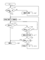
- the block diagram for demonstrating the vehicle seat apparatus of the 1st Embodiment of this invention The flowchart for demonstrating the process of ECU (Electronic
- the flowchart for demonstrating the process of ECU of 1st Embodiment The flowchart for demonstrating the process of ECU of 1st Embodiment.
- the flowchart for demonstrating the process of ECU of another example The flowchart for demonstrating the process of ECU of another example.
- the flowchart for demonstrating the process of ECU of another example The flowchart for demonstrating the process of ECU of another example.
- the flowchart for demonstrating the process of ECU of another example The flowchart for demonstrating the process of ECU of another example.
- the seat 1 includes a seat cushion 2 that forms a seating surface, and a seat back 3 that is supported to be tiltable at the rear end portion of the seat cushion 2.
- the seat 1 is provided with a lock mechanism 4 that restricts the sliding movement of the seat 1. Further, the seat 1 is provided with a motor M as a drive source for driving the lock mechanism 4 so as to restrict the sliding movement of the seat 1 by the lock mechanism 4 and to release the restriction.
- the seat 1 of the present embodiment is provided so as to be slidable along a lower rail (not shown) that is fixed to the vehicle floor and extends in the vehicle front-rear direction, and the lock mechanism 4 is for restricting the sliding movement.
- the lock mechanism 4 is a known mechanism, and specifically, the slide 1 is slid by inserting a lock claw provided in the seat 1 into any one of a number of lock holes formed in the lower rail. It restricts movement.
- the motor M has an output portion that can selectively move, that is, rotate in the forward and reverse directions. Further, the motor M is connected to the lock mechanism 4 at its output part, and exerts a self-binding force that does not move in the non-energized state, and the output part is regulated by the lock mechanism 4 according to the energization direction. It can be selectively driven in two directions, a forward direction that is a release direction and a reverse direction that is a restricting direction. Further, the motor M is provided with a rotation sensor S that can detect the number of rotations of its own rotation shaft connected to the output unit.
- the sheet 1 includes, for example, a release limit switch 5 as a release detection unit that detects that the restriction by the lock mechanism 4 is released by contact / non-contact with a part of the lock claw or the output unit,
- a regulation limit switch 6 is provided as a regulation detection unit that detects that regulation by the lock mechanism 4 is being performed.
- the seat 1 includes an ECU (Electronic Control Unit) 7 as a control unit for controlling the motor M, a side switch 8 as an operation switch for operating restriction and release by the lock mechanism 4, and a rear surface.
- a switch 9 is provided.
- the side switch 8 is disposed on the side surface of the seat cushion 2, and the back switch 9 is disposed on the back surface of the seat back 3.
- the side switch 8 or the back switch 9 keeps the released state in the energized (pressed) state, and automatically returns to the restricted state when the energized (not pushed) state. This is a set of automatic return type push button operation switches.
- the seat 1 is provided with a seating sensor 10 that can detect whether or not a passenger is seated on the seat 1.
- the ECU 7 includes an electric motor M (including a rotation sensor S), a release limit switch 5, a restriction limit switch 6, a side switch 8 or a back switch 9, and a seating sensor 10. It is connected to the.
- the ECU 7 is connected to a vehicle speed sensor 11, a collision detection sensor 12, a collision detection sensor 13, and a notification unit 14 via an in-vehicle network CAN (controller area network) or a module (not shown).
- the collision detection sensor 12 is, for example, an acceleration sensor that can detect that the vehicle has collided or has collided.
- the collision detection sensor 13 is, for example, a rear radar capable of detecting the distance to the following vehicle and detecting that there is a possibility or high possibility of a collision.
- the notification unit 14 is an indicator including a car navigation display, a warning lamp, or the like that enables visual notification, or a speaker that enables auditory notification.
- the ECU 7 is further connected to components such as an ignition sensor 15 and a door courtesy switch 16 via an in-vehicle network CAN and a module (not shown).
- the ECU 7 controls the energization of the motor M based on the operation of the operation switch (the side switch 8 or the back switch 9).
- the ECU 7 starts the processing shown in FIG. 2 and operates the operation switch (the side switch 8 or the back switch 9).
- the motor M is controlled so as to maintain the state where the restriction by the lock mechanism 4 is performed until a preset release condition that is excluded from the conditions is satisfied (release restriction control).
- the release condition of the present embodiment is a vehicle speed release condition that is satisfied when the vehicle speed is 0 when the operation switch (side switch 8 or back switch 9) is operated. That is, in step S11, the ECU 7 determines whether or not the vehicle speed detected by the vehicle speed sensor 11 is 0. If it is determined that the vehicle speed is 0, the process proceeds to step S12. If the vehicle speed detected by the vehicle speed sensor 11 is not 0, that is, the vehicle is running, step S11 is repeated.
- step S12 the ECU 7 starts energizing the motor M so that the output unit is driven in the positive direction, which is the direction in which the restriction by the lock mechanism 4 is released, and the process proceeds to step S13.
- step S13 the ECU 7 determines whether or not the release limit switch 5 detects that the restriction by the lock mechanism 4 has been released. When it is detected that the release has been released, the ECU 7 proceeds to step S14. Stop energization of the motor M. If it is not detected that the release has been made, the ECU 7 shifts the process to step S15.
- step S15 the ECU 7 determines whether a preset time (for example, 3 seconds) has elapsed since the start of energization. If the preset time (for example, 3 seconds) has not elapsed, the ECU 7 Return to S13. That is, the ECU 7 releases the restriction based on the operation of the operation switch (the side switch 8 or the back switch 9) with the release limit switch 5 within a range in which a preset time (for example, 3 seconds) does not elapse. Energization is performed to the motor M so that the output unit moves in the positive direction until the detection is detected.
- a preset time for example, 3 seconds
- the time set in advance in step S15 (for example, 3 seconds) is a time when it is detected that the restriction has been released first by the release limit switch 5 without passing if the operation is performed normally. This is the time that elapses when some failure occurs in the power transmission path.
- step S15 the ECU 7 proceeds to step S16 when a preset time (for example, 3 seconds) elapses.
- a preset time for example, 3 seconds
- step S ⁇ b> 16 the ECU 7 stops energization of the motor M, operates the notification unit 14 to the notification state, notifies the fact (for example, that the release has not been performed normally), and performs the processing step.
- the process proceeds to S17. That is, the ECU 7 stops energization of the motor M when a preset forced stop condition excluding detection by the release limit switch 5 or the restriction limit switch 6 is satisfied while the motor M is energized.
- the forced stop condition of the present embodiment is a time lapse forced stop condition that is satisfied when a preset time (for example, 3 seconds) elapses.
- step S17 the ECU 7 determines whether or not the forced stop count value is “3”. If it is not “3”, the process proceeds to step S18. In step S18, the ECU 7 increments the forced stop count value (initial value is “0”) by 1 (+1), and returns to step S12. If the forced stop count value is “3” in step S17, the process proceeds to step S14, and the state where the energization to the motor M is stopped is held. That is, the ECU 7 stops the energization of the motor M when a preset time (for example, 3 seconds) elapses without the release being detected by the release limit switch 5, and then performs retry control for energizing the motor M again. , A preset number of times (three times in this example).
- a preset time for example, 3 seconds
- step S21 when the side switch 8 is pushed to release the regulation by the lock mechanism 4, the ECU 7 performs the process (regulation restriction control) shown in FIG. 3 in parallel with the process shown in FIG. In step S21, the operation of other operation switches (other than the operated side switch 8), that is, the rear switch 9, is invalidated, and the process proceeds to step S22.
- the process regulation restriction control
- step S22 the ECU 7 determines whether or not a preset time (for example, 3 minutes) has elapsed.
- a preset time for example, 3 minutes
- the ECU 7 proceeds to step S23, and other operation switches. That is, the operation of the back switch 9 is made effective. If the preset time (for example, 3 minutes) has not elapsed, step S22 is repeated.
- the time end condition that is satisfied when a preset time (for example, 3 minutes) elapses is set as a priority end condition (a condition for ending priority on the previously operated operation switch). ing.
- the ECU 7 starts the control of the motor M based on the operation of the operation switch (side switch 8) that is operated first among the side switch 8 and the back switch 9, and then the time end condition (priority end condition) Until the condition is satisfied, the operation of the other operation switch (rear switch 9) is invalidated.
- step S13 when it is detected that the restriction is released in step S13 (see FIG. 2), the ECU 7 starts the process shown in FIG. 4 in parallel with the process in step S14.
- step S31 the ECU 7 determines whether or not the collision detection sensor 12 and the collision detection sensor 13 have detected a vehicle collision or a possibility of a vehicle collision, If it is determined that a vehicle collision has been detected or there is a possibility of a vehicle collision, the ECU 7 proceeds to step S32. If it is determined that no vehicle collision has been detected and there is no possibility of a vehicle collision, step S31 is repeated.
- step S ⁇ b> 32 the ECU 7 energizes the motor M so that the output unit moves in the reverse direction, which is the direction in which the lock mechanism 4 performs the regulation, performs regulation by the lock mechanism 4, and informs the informing unit 14 in the notification state.
- the restriction by the lock mechanism 4 for an emergency state For example, the restriction by the lock mechanism 4 for an emergency state. That is, when the restriction by the lock mechanism 4 is released based on the operation of the operation switch (the side switch 8 or the back switch 9), the ECU 7 sets a preset forced restriction condition that excludes the operation of the operation switch from the condition. When satisfied, the motor M is controlled so as to be regulated by the lock mechanism 4 regardless of the operation of the operation switch (forced regulation control).
- the forcible restriction condition is an emergency condition that is satisfied when a vehicle collision is detected or when it is determined that there is a possibility of a vehicle collision.
- the ECU 7 starts the processing shown in FIG.
- the motor M is controlled so as to maintain the state where the restriction by the lock mechanism 4 is released until a preset restriction condition that is excluded from is satisfied (regulation restriction control).
- the restriction condition of the present embodiment is a time passage restriction condition that is satisfied when a preset time (for example, 10 seconds) has elapsed since the operation switch (side switch 8 or back switch 9) is operated. ing. That is, in step S41, it is determined whether a preset time (for example, 10 seconds) has elapsed since the operation switch (side switch 8 or back switch 9) was operated (after the automatic return). If the ECU 7 determines that a preset time (for example, 10 seconds) has not elapsed, the ECU 7 proceeds to step S42. In step S42, the ECU 7 operates the notification unit 14 to the notification state to notify the fact (for example, that the state is still released), and returns to step S41.
- a preset time for example, 10 seconds
- step S41 when the preset time (for example, 10 seconds) has elapsed in step S41, the ECU 7 proceeds to step S43.
- the preset time for example, 10 seconds
- step S ⁇ b> 43 the ECU 7 puts the notification unit 14 into a non-notification state (for example, terminates the notification that the released state is still maintained), and the output unit regulates the lock mechanism 4.
- the energization of the motor M is started so as to drive in the reverse direction, and the process proceeds to step S44.
- step S44 the ECU 7 determines whether or not the restriction by the lock mechanism 4 is detected by the restriction limit switch 6. When the restriction is detected, the ECU 7 proceeds to step S45. Stop energization of the motor M. On the other hand, if it is not detected that the restriction is made, the ECU 7 shifts the process to step S46.
- step S46 the ECU 7 determines whether or not a preset time (for example, 3 seconds) has elapsed since the start of energization. If the preset time (for example, 3 seconds) has not elapsed, the ECU 7 Return to S44. That is, when the ECU 7 performs the restriction based on the operation of the operation switch (the side switch 8 or the back switch 9), the restriction is performed by the restriction limit switch 6 within a range in which a preset time (for example, 3 seconds) does not elapse.
- the motor M is energized so that the output unit moves in the reverse direction until it is detected, and when regulation is detected, the motor M is de-energized.
- the time set in advance in step S46 (for example, 3 seconds) is the time when it is detected that the restriction is first performed by the restriction limit switch 6 without passing if it operates normally. This is the time that elapses when some failure occurs in the power transmission path or the like.
- step S46 when a preset time (for example, 3 seconds) elapses, the ECU 7 proceeds to step S47.
- a preset time for example, 3 seconds
- step S47 the ECU 7 stops energization of the motor M, operates the notification unit 14 to the notification state, notifies the fact (for example, that regulation is not normally performed), and performs the processing step.
- the process proceeds to S48.
- step S48 the ECU 7 determines whether or not the forced stop count value is “3”. If it is not “3”, the process proceeds to step S49. In step S49, the ECU 7 increments the forced stop count value (initial value is “0”) by 1 (+1), and returns to step S43. In step S48, if the forced stop count value is "3", the process proceeds to step S45, and the state where the energization to the motor M is stopped is held. That is, the ECU 7 stops the energization of the motor M when a preset time (for example, 3 seconds) elapses without the restriction being detected by the restriction limit switch 6, and then performs retry control for energizing the motor M again. , A preset number of times (three times in this example).
- a preset time for example, 3 seconds
- the restriction by the lock mechanism 4 is not released during traveling.
- the vehicle speed is 0, that is, when the vehicle is stopped, energization to the motor M is started in a direction to release the regulation.
- the operation of other operation switches is invalidated for a preset time (for example, 3 minutes).
- the release limit switch 5 detects that the restriction by the lock mechanism 4 is released, the energization of the motor M is stopped. In addition, after it is detected that the restriction has been released, if it is determined that the vehicle collision is detected by the collision detection sensor 12 and the collision detection sensor 13 or that there is a possibility of the vehicle collision, the restriction is performed in the direction in which the restriction is performed.
- the motor M is energized and regulated by the lock mechanism 4 and is notified by the notification unit 14.
- a preset time for example, 3 seconds
- Retry control for energizing M is performed a preset number of times (three times in this example).
- the side switch 8 when the hand is released from the side switch 8 in a state where the restriction by the lock mechanism 4 is released and the energization to the motor M is stopped, the side switch 8 is automatically restored, and then a preset time (for example, The state where the restriction is released is maintained until 10 seconds), and the notification unit 14 notifies the fact. Then, when a preset time (for example, 10 seconds) elapses, energization of the motor M is started in the direction in which the regulation is performed.
- a preset time for example, 10 seconds
- the restriction limit switch 6 detects that the restriction by the lock mechanism 4 has been performed, the energization of the motor M is stopped. In addition, when the restriction limit switch 6 does not detect that the regulation has been performed and a preset time (for example, 3 seconds) has elapsed since the start of energization, the energization of the motor M is stopped, and then the motor is again activated. Retry control for energizing M is performed a preset number of times (three times in this example).
- the motor M is energized to drive the output unit in the reverse direction (regulation direction) until the regulation limit switch 6 detects the regulation.
- the regulation is detected, the power supply to the motor M is stopped. Therefore, the flow of current is interrupted after the regulation by the lock mechanism 4 is performed. For these reasons, it is possible to avoid the current from continuing to flow through the motor M, and to reduce the power consumption.
- the forced stop condition is a time lapse forced stop condition that is satisfied when a preset time (for example, 3 seconds) elapses.
- a preset time for example, 3 seconds
- the release limit switch 5 or the restriction limit Even if some failure occurs in the switch 6, it is possible to prevent the current from continuing to flow through the motor M when a preset time (for example, 3 seconds) elapses.
- the notification unit 14 When the forced stop condition (time lapse forced stop condition) is satisfied, the notification unit 14 is activated in the notification state by the ECU 7 to notify that fact. Therefore, the passengers can easily know that the forced stop condition (time lapse forced stop condition) is satisfied.
- the ECU 7 When the ECU 7 performs the restriction by the lock mechanism 4 based on the operation of the operation switch (the side switch 8 or the back switch 9), the ECU 7 is locked until a preset restriction condition excluding the operation switch operation is satisfied.
- the motor M is controlled so that the state where the restriction by the mechanism 4 is released is maintained.
- the restriction condition is a time passage restriction condition that is satisfied when a preset time (for example, 10 seconds) has elapsed since the operation switch was operated.
- the state where the restriction by the lock mechanism 4 is released is maintained until (for example, 10 seconds) elapses. Therefore, for example, even when the operation switch is not operated, the seat 1 can be freely moved until a preset time elapses, and convenience can be improved.
- the operation switch (the side switch 8 or the back switch 9) keeps the released state in the energized (pressed) state, and releases the hand when it is not energized (pressed).
- an automatic return type push button operation switch that automatically returns to a regulated state. Therefore, even after releasing the operation switch, the seat 1 can be moved freely until the regulation condition is satisfied, and convenience can be improved.
- the operation switch (side switch 8 or back switch 9) includes a back switch 9 disposed on the back of the seat back 3. Therefore, for example, it is possible to move the seat 1 freely until the regulation condition is satisfied even after the passenger in the seat behind the seat back 3 urges (presses) the rear switch and releases the hand. Therefore, it is possible to easily go out of the vehicle through the front vehicle door.
- the notification unit 14 When performing the regulation by the lock mechanism 4 based on the operation of the operation switch, the notification unit 14 is operated to the notification state until the regulation condition is satisfied by the ECU 7 (for example, a state in which the notification is still released) Is held). Therefore, the passenger can easily know that the state where the restriction by the lock mechanism 4 is released is maintained.
- the release condition is a vehicle speed release condition that is satisfied when the vehicle speed is 0 when the operation switch is operated. Therefore, until the vehicle speed becomes 0, that is, while the vehicle is traveling. The state in which the restriction by the lock mechanism 4 is performed is maintained. Therefore, for example, it is possible to prevent the seat 1 from sliding unexpectedly due to the behavior of the vehicle.
- the motor M is controlled by the ECU 7 based on the operation of the operation switch (for example, the side switch 8) operated first among the side switch 8 and the back switch 9, and then another operation is performed until the priority termination condition is satisfied.
- the operation of the switch for example, the rear switch 9) is invalidated. Therefore, the operation of the operation switch that has been operated first is given priority, and for example, it is possible to prevent an abnormal operation from being performed by operating another operation switch.
- the priority end condition includes a time end condition that is satisfied when a preset time (for example, 3 minutes) has elapsed
- the other end of the operation switch is set until the preset time (for example, 3 minutes) has elapsed.
- the operation is invalidated. Therefore, for example, the operation of the operation switch that has been operated first can be prioritized and an abnormal operation can be suppressed, and a state in which the restriction is canceled due to some abnormality such as sticking of the operation switch is preset.
- the lock mechanism 4 can be controlled by operating another operation switch.
- the compulsory restriction condition is an emergency condition that is satisfied when a vehicle collision is detected or when it is determined that there is a possibility of a vehicle collision.
- the sheet 1 can be fixed by quickly regulating the lock mechanism 4.
- the notification unit 14 When the compulsory restriction condition (emergency condition) is satisfied, the notification unit 14 is activated to notify the fact. Therefore, the passengers can easily know that the compulsory restriction condition (emergency condition) is satisfied.
- the release condition (see step S11 in FIG. 2) in the above embodiment may be changed to another release condition.
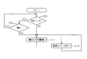
- the release condition may be a seat release condition that is satisfied when no passenger is seated on the seat 1 when the rear switch 9 is operated (see FIG. 6).
- step S51 the ECU 7 operates the operation switch operated in step S51 as shown in FIG. Is not the back switch 9, and if it is not the back switch 9 (the side switch 8), the process proceeds to step S12 (refer to FIG. 2 hereinafter).
- the ECU 7 shifts the process to step S52.
- step S ⁇ b> 52 the ECU 7 determines whether a passenger is seated on the seat 1 based on information detected by the seating sensor 10. When the ECU 7 determines that the passenger is not seated on the seat 1, the ECU 7 shifts the processing to the step S12 (hereinafter, refer to FIG. 2). If seated, the process returns to step S51.
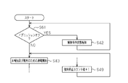
- the restriction condition may be an ignition restriction condition that is satisfied when the ignition is turned on if the ignition is turned off when the operation switch is operated (see FIG. 7).
- step S61 when the restriction by the lock mechanism 4 is released and the energization of the motor M is stopped, when the hand is released from the side switch 8 (when the side switch 8 is automatically restored), the ECU 7 performs an ignition in step S61. Based on the information detected by the sensor 15, it is determined whether or not the ignition is off (on). If the ECU 7 determines that the ignition is off, the ECU 7 proceeds to step S42. In step S42, the ECU 7 operates the notification unit 14 in the notification state to notify the fact (for example, that the state is still released), and returns to step S61. If the ECU 7 determines in step S61 that the ignition is on, the process proceeds to step S43 (refer to FIG. 5 hereinafter).
- the seat 1 can be freely moved until the ignition is turned on, and convenience can be improved.
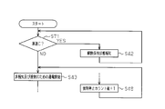
- the regulation condition may be a vehicle speed regulation condition that is satisfied when the vehicle speed is zero when the operation switch is operated and the vehicle speed becomes zero (see FIG. 8).
- step S71 determines the vehicle speed. It is determined whether or not the vehicle speed detected by the sensor 11 is zero. If the ECU 7 determines that the vehicle speed is 0, the process proceeds to step S42. In step S42, the ECU 7 operates the notification unit 14 in the notification state to notify the fact (for example, that the state is still released), and returns to step S71. If the ECU 7 determines in step S71 that the vehicle speed is not 0, that is, the vehicle is running, the process proceeds to step S43 (refer to FIG. 5 hereinafter).
- the seat 1 can be freely moved until the vehicle moves, and convenience can be improved.
- the restriction condition may be a door restriction condition that is satisfied when the vehicle door is in an open state when the operation switch is operated (see FIG. 9).
- step S81 the ECU 7 updates the information detected by the door courtesy switch 16 in step S81. Based on this, it is determined whether the vehicle door is open (off) or closed (on). When the ECU 7 determines that the vehicle door is in the open state (off), the process proceeds to step S42. In step S42, the ECU 7 operates the notification unit 14 in the notification state to notify the fact (for example, that the state is still released), and returns to step S81. If the ECU 7 determines in step S81 that the vehicle door is closed (ON), the process proceeds to step S43 (refer to FIG. 5 hereinafter).
- the seat 1 can be moved freely until the vehicle door is closed, and convenience can be improved.
- the restriction condition may be a restriction condition after the collision that is satisfied when the collision detection flag is reset if the collision is detected when the operation switch is operated (see FIG. 10).
- step S91 when the restriction by the lock mechanism 4 is released and the energization to the motor M is stopped, when the hand is released from the side switch 8 (when the side switch 8 automatically returns), the ECU 7 performs a collision in step S91. It is determined whether or not the vehicle collision is detected by the detection sensor 12. If the ECU 7 determines that the vehicle collision has been detected, the ECU 7 proceeds to step S42. Whether or not a vehicle collision is detected by the collision detection sensor 12 is determined by a collision detection flag. Specifically, the collision detection flag is set to “1” when a vehicle collision is detected. Is “1” or not (“0”). If the ECU 7 determines that the collision detection flag is “1”, the process proceeds to step S42.
- step S42 the ECU 7 operates the notification unit 14 to the notification state to notify the fact (for example, that the state is still released), and returns to step S91. If the ECU 7 determines in step S91 that a vehicle collision is not detected, that is, the collision detection flag is “0”, the process proceeds to step S43 (refer to FIG. 5 hereinafter).
- the seat 1 can be freely moved after the collision is detected, and the convenience can be improved.
- the compulsory restriction condition (see step S31 in Fig. 4) of the above embodiment may be changed to another compulsory restriction condition.
- the forced restriction condition may be a time lapse forced restriction condition that is satisfied when a preset time (for example, 20 seconds) elapses after the restriction by the lock mechanism 4 is released in a state where the vehicle speed is not zero (FIG. 11). reference).
- a preset time for example, 20 seconds
- step S13 when it is detected that the restriction is released in step S13 (see FIG. 2), the ECU 7 starts the process shown in FIG. 11 in parallel with the process in step S14.
- step S101 the ECU 7 determines whether or not a preset time (for example, 20 seconds) has elapsed after the restriction is released in a state where the vehicle speed is not zero. If the ECU 7 determines that a preset time (for example, 20 seconds) has elapsed while the vehicle speed is not 0, the process proceeds to step S102. If the preset time (for example, 20 seconds) has not elapsed while the vehicle speed is not 0, step S101 is repeated.
- a preset time for example, 20 seconds
- step S ⁇ b> 102 the ECU 7 energizes the motor M so that the output unit moves in the reverse direction, which is the direction in which the lock mechanism 4 is regulated, regulates the lock mechanism 4, and informs the notification unit 14 in the notification state. To that effect (for example, performing a restriction by the lock mechanism 4).
- the lock mechanism 4 is regulated and the seat 1 can be fixed. Accordingly, it is possible to forcibly prevent the state in which the restriction is released during traveling from continuing for a long time (for example, longer than 20 seconds).
- the seat 1 is provided so as to be slidable along the lower rail extending in the vehicle front-rear direction, and the lock mechanism 4 is for restricting the sliding movement along the vehicle front-rear direction.
- the direction of slide movement is not limited to this.
- the seat 1 may be embodied in the case where the seat 1 is provided so as to be slidable along the vehicle longitudinal direction and the vehicle width direction.
- the lock mechanism 4 a front-rear direction lock mechanism for restricting the sliding movement of the seat 1 along the vehicle front-rear direction, and a width direction for restricting the slide movement of the seat 1 along the vehicle width direction.
- It has a configuration including a lock mechanism and a front-rear direction operation switch and a width direction operation switch as corresponding operation switches.
- the ECU 7 controls the motor M based on the operation of the front / rear direction operation switch or the width direction operation switch that has been operated first, and then disables the operation of other operation switches until the direction priority end condition is satisfied.
- the direction priority end condition is, for example, a time end condition that is satisfied when a preset time (for example, 3 minutes) elapses, as in the priority end condition.
- a preset time for example, 3 minutes
- the operation of the front / rear direction operation switch or the width direction operation switch operated first is given priority, and the release of the restriction by the front / rear direction lock mechanism and the release of the restriction by the width direction lock mechanism are performed simultaneously. Can be prevented.
- the front-rear direction operation switch and the width direction operation switch may be arranged on the side surface of the seat cushion 2 (having a side switch) and arranged on the back surface of the seat back 3 (having a rear surface switch). However, only one of each may be provided.
- the motor M (drive source) can selectively drive the output portion in two directions, the forward direction and the reverse direction, and is driven by the forward / backward lock mechanism by driving in the forward direction from the neutral position. You may provide so that regulation may be cancelled
- the motor M (drive source) can be compared with the case where each of the two lock mechanisms is provided with a drive source while the restriction by the two lock mechanisms (the front-rear direction lock mechanism and the width direction lock mechanism) can be released. ) Can be reduced (to one). Since the motor M (drive source) is generally heavy and expensive, for example, by reducing the number of the motor M (drive source), for example, the seat 1 to be mounted can be reduced in weight and price. be able to.
- the release detection unit (release limit switch 5) includes a front / rear direction release limit switch (front / rear direction release detection unit) that detects that the restriction by the front / rear direction lock mechanism is released, and the width direction lock mechanism. It is good also as a structure provided with the width direction cancellation
- the ECU 7 may activate the notification unit 14 in the notification state to notify that effect.
- the ECU 7 is in parallel with the normal operation process (for example, see FIGS. 2 and 5), The process shown in FIG. 12 is started.
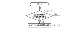
- the ECU 7 proceeds to step S112, and the operation switch (front / rear direction operation switch and width direction) is detected.
- the operation of the operation switch) is invalidated, and the notification unit 14 is activated to notify the state.
- step S111 is repeated.
- the ECU 7 determines that a vehicle collision is detected or there is a possibility of a vehicle collision when the emergency condition is satisfied, that is, in step S31 shown in FIG. Then, the motor M may be controlled so that the restriction by the lock mechanism 4 is performed faster than usual. In normal times, the motor M is driven at an optimum speed in consideration of various effects such as noise and vibration of the motor M. On the other hand, when the emergency condition is satisfied, the noise and vibration increase. However, the motor M is driven at a speed faster than normal.
- the seat 1 can be fixed by causing the lock mechanism 4 to perform regulation more quickly.
- the release detection unit and the restriction detection unit are limit switches (the release limit switch 5 and the restriction limit switch 6), but are not limited to this, and the restriction by the lock mechanism 4 is released. It is good also as other cancellation
- the release detection unit and the regulation detection unit may be the rotation sensor S or the lock current detection unit. In the case of the rotation sensor S, for example, it may be detected based on the number of pulses output from the rotation sensor S that the restriction is released or the restriction is being performed.
- the restriction may be detected that the restriction has been released or that the restriction has been performed based on the time since the stop (that is, it is determined that the stop has occurred mechanically).
- the lock current detection unit for example, the current value to be energized is detected, and the restriction is released based on the current value (that is, it is determined that the lock current has been mechanically stopped) May be detected.
- the release detection unit and the regulation detection unit may be timers. In this case, the forced stop condition of the above embodiment (the time lapse forced stop condition that is satisfied when a preset time elapses) is used. It becomes impossible to adopt.
- the forced stop condition is the time lapse forced stop condition that is satisfied when a preset time has elapsed, but the present invention is not limited to this and may be changed to another condition.
- the number of pulses output from the rotation sensor S is a preset number.
- the seat 1 includes an ottoman
- the ECU 7 stores the ottoman when releasing the restriction based on the operation of the operation switch. Good. If it does in this way, when a restriction
- the ECU 7 cancels the restriction by the lock mechanism 4 regardless of the operation of the operation switch when the seat back 3 is tilted forward (so-called large tilt).
- the motor M may be controlled. Further, the ECU 7 may control the motor M so that when the seat back 3 is raised thereafter, the lock mechanism 4 performs regulation regardless of the operation of the operation switch. In this way, for example, it is possible to easily carry out that the passenger who was in the seat behind the seat back goes out of the vehicle through the vehicle door on the front side, and convenience can be improved.
- a vehicle seat device according to a second embodiment embodying the present invention will be described below with reference to FIGS.
- the lock mechanism 4 is regulated and released by the control of the ECU 7, but in the second embodiment, the lock mechanism 4 is regulated and released by the control of the ECU.
- This is realized by a typical configuration.
- members similar to those in the first embodiment are denoted by the same reference numerals, and description thereof is omitted.
- the vehicle seat 1 is provided with a motor M as a drive source for releasing the restriction of the lock mechanism 4.
- the seat 1 of the present embodiment is provided so as to be movable along a lower rail (not shown) that is fixed to the vehicle floor and extends in the vehicle front-rear direction, and the lock mechanism 4 is for restricting the movement of the seat 1.
- the lock mechanism 4 is a known mechanism. Specifically, the lock mechanism 4 is moved by inserting a lock claw provided in the seat 1 into any one of a number of lock holes formed in the lower rail. Is to regulate.
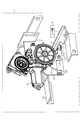
- the motor M is fixed to the frame of the seat 1 through a bracket 34 made of a metal plate material.
- the motor M can rotate the output member 35 as an output portion in the forward and reverse directions according to the energization direction.
- the output member 35 is made of a metal plate and is supported rotatably with respect to the bracket 34.
- the output member 35 is formed with a sector gear portion 35a having a substantially fan shape, that is, a partial circular shape. When the sector gear of the sector gear portion 35 a is engaged with the output rotation shaft of the motor M, the output member 35 can be rotated by driving the motor M.
- the output member 35 is formed with an output piece 35b extending.
- the output piece 35b is inclined slightly downward (about 5 °) as shown in FIG.
- the motor M has a self-binding force that prevents the output member 35 from moving (turning) in a non-energized state.
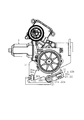
- the seat 1 is provided with a first limit switch 36 as a first switch element that switches at a first switching position (see FIG. 17) in the forward direction with respect to the regulation / release position (see FIG. 16) of the output member 35. It has been. Also, the seat 1 has second limit switches 21 and 22 as second switch elements that switch at a second switching position (see FIG. 15) in the opposite direction to the restriction / release position (see FIG. 16). Is provided. The first and second limit switches 36, 21, 22 are turned on while the levers 36b, 21b, 22b extending from the switch body portions 36a, 21a, 22a are pushed.
- a release lever 31 as a release member capable of releasing the restriction is connected to the lock mechanism 4 via a lock mechanism connecting portion 32.
- the release lever 31 does not release the restriction by the lock mechanism 4 in a substantially horizontal state, and is lifted together with the lock mechanism connecting portion 32 as shown in FIGS.
- the lock mechanism 4 is connected to the lock mechanism 4 so that the restriction by the lock mechanism 4 is released, that is, the lock claw is removed from the lock hole.
- the release lever 31 is set so as not to mechanically move below the substantially horizontal state, that is, not tilted downward.
- the output member 35 moves the second limit switches 21 and 22 to the release lever 31 at the second switching position (the output piece 35b is substantially horizontal) as shown in FIG. 14 and is provided so as to be in a disengaged state at a position in the opposite direction to the second switching position as shown in FIG.
- the second limit switches 21 and 22 are arranged in a range shown in FIGS. 15 to 17 so that the levers 21b and 22b lift the release lever 31 upward together with the output piece 35b, that is, are pressed by the release lever 31. Has been. In such a state where the power transmission is performed, the levers 21b and 22b are surely pushed (on state). Further, in the present embodiment, the pair of second limit switches 21 and 22 are arranged in parallel so that the levers 21b and 22b are pushed in at the same time (on state) so as to be switched simultaneously. Yes.
- the first limit switch 36 is at a position corresponding to the sector gear portion 35a in the bracket 34, and its lever 36b is in the first switching position, that is, the output piece 35b is horizontal as shown in FIG. It is disposed so as to be pushed into the sector gear portion 35a (on state) at a position inclined upward by about 20 °.
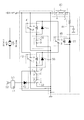
- a pair of power supply terminals of the motor M are connected to common contacts C of the forward rotation relay 41 and the reverse rotation relay 42.
- Each contact A of the forward rotation relay 41 and the reverse rotation relay 42 is connected to a DC power source (battery) BA, and each contact B is connected to the ground.
- an operation switch 43 is provided on the side surface of the seat cushion in the seat 1.
- the operation switch 43 is an automatic return type push button switch, and the contact A and the contact B are connected while an operation of releasing the restriction by the lock mechanism 4 is performed.
- the contact A of the operation switch 43 is connected to the DC power supply BA.
- the contact B of the operation switch 43 is connected to one end of a coil of the relay 45 via the chattering prevention circuit 44, and the other end of the coil is connected to the ground.
- the common contact C of the relay 45 is connected to the DC power supply BA, the contact A of the relay 45 is connected to one end of the coil of the forward rotation relay 41, and the other end of the coil is connected to the first limit switch 36. Connected to ground.
- the first limit switch 36 brings the contact point A and the contact point B of the first limit switch 36 into a disconnected state when the lever 36b is pushed in.
- the first limit switch 36 connects the contact point A and the contact point B of the first limit switch 36 in an off state where the lever 36b is not pushed.
- the contact B of the relay 45 is connected to one end of a coil of the reverse rotation relay 42, and the other end of the coil is connected to the ground via the second limit switches 21 and 22.
- the second limit switches 21 and 22 connect the common contact C and the contact A when the lever 36b is pushed in, and connect the contact C and the contact B when the lever 36b is turned off. It is what.
- the other end of the coil of the reverse rotation relay 42 is connected to the contact A of the second limit switch 21, and the contact C of the second limit switch 21 is the contact of the other second limit switch 22.
- the contact point A of the second limit switch 22 is connected to the ground.
- the vehicle seat device of the second embodiment includes an indicator 51 and a buzzer 52 as a notification unit for notifying the state where the restriction by the lock mechanism 4 is released.
- the indicator 51 of the second embodiment is a warning lamp provided in a part of the meter 53 that performs various displays.
- the indicator 51 and the buzzer 52 are connected to the contact B of the second limit switch 22 through a diode 54.
- the contact B of the second limit switch 21 is connected to the ground.
- the indicator 51 and the buzzer 52 are inactivated when connected to the ground, and are activated when they are electrically opened to visually and audibly notify the passenger.
- flywheel diodes 55 to 57 are connected in parallel to both ends of the coil of the forward rotation relay 41, both ends of the coil of the reverse rotation relay 42, and both ends of the coil of the relay 45, respectively.
- the first limit switch 36 is turned on (the contact A and the contact B are not connected). As a result, no current flows through the coil of the forward rotation relay 41, and the forward rotation relay 41 is turned off (the contact C is connected to the contact B). Then, supply of drive current to the motor M, that is, energization is stopped. That is, while the operation switch 43 is being pressed, the first limit switch 36 energizes the output member 35 to rotate in the forward direction until it switches to the on state, and when it switches to the on state, the motor It functions to stop energizing M.
- a current flows through the coil of the relay 45.
- the relay 45 is turned off (the contact C is connected to the contact B).
- a current flows through the coil of the reverse rotation relay 42 via the relay 45, and the reverse rotation relay 42 is turned on (the contact C is connected to the contact A).
- a drive current is supplied to the motor M in the reverse direction (upward in FIG. 18) via the reverse rotation relay 42, that is, energization is performed to rotate the output member 35 in the reverse direction, and the output member 35 is reversed. Rotated in the direction.
- the output member 35 is engaged with the release lever 31 connected so as to be able to release the restriction by the lock mechanism 4 via the second limit switches 21 and 22 at the second switching position, and the second It is provided so as to be in a disengaged state at a position in the opposite direction from the switching position. Therefore, when the power transmission to the release lever 31 is being performed, the second limit switches 21 and 22 can be reliably switched (on state).
- the vehicle seat device includes a notification unit (indicator 51 and buzzer 52) that notifies the state where the restriction by the lock mechanism 4 is released, the passenger visually indicates the state where the restriction by the lock mechanism is released. And it can be easily heard.
- a notification unit indicator 51 and buzzer 52
- the notification unit (indicator 51 and buzzer 52) is not notified by the second limit switches 21 and 22 so as to be in the notification state when the output member 35 is in the positive direction from the second switching position. It is switched between notification states. Therefore, the notification unit can be operated by using the second limit switches 21 and 22 having a function of stopping energization of the motor M in common.
- the second embodiment may be modified as follows.
- the output member 35 is engaged via the second limit switches 21 and 22 at the second switching position with respect to the release lever 31 that is coupled so that the restriction by the lock mechanism 4 can be released.
- the present invention is not limited to this, and other configurations may be used.
- the second limit switches 21 and 22 may be configured so that the levers 21 b and 22 b are pushed by the output member 35 while being fixed to the bracket 34, similarly to the first limit switch 36.
- the release lever 31 may be omitted.
- the output member 35 may be directly connected to the lock mechanism 4 or connected via a wire.
- the notification unit (the indicator 51 and the buzzer 52) that notifies the state where the restriction by the lock mechanism 4 is released is provided.
- the notification unit is not limited to this, and the notification unit is omitted. Also good.
- the notification unit may include any one of the indicator 51 and the buzzer 52. That is, the notification unit may be configured to notify visually or audibly or both. Alternatively, the notification unit may be changed to something other than the indicator 51 and the buzzer 52.
- the notification unit (indicator 51 and buzzer 52) is switched between the notification state and the non-notification state by the second limit switches 21 and 22, but this is not limitative. Instead, it may be switched between the notification state and the non-notification state by another switch element. Further, when the notification unit is omitted as described above, or when the switch is operated by another switch element, the number of the second limit switches 21 and 22 may be only one.
- the first and second limit switches 36, 21, and 22 of the second embodiment may be changed to other switch elements as long as they have similar functions.
- the above-described circuit may be changed as long as it functions similarly without using a microcomputer.
- each element forward rotation relay 41, reverse rotation relay 42, and relay 45
- the lock mechanism 4 regulates the movement of the seat 1 in the vehicle front-rear direction, but is not limited thereto, and may restrict other movements of the seat 1.
- the lock mechanism 4 may restrict the tilt of the seat back that can be tilted with respect to the seat cushion that forms the seating surface of the seat 1.
Landscapes
- Engineering & Computer Science (AREA)
- Aviation & Aerospace Engineering (AREA)
- Transportation (AREA)
- Mechanical Engineering (AREA)
- Human Computer Interaction (AREA)
- Seats For Vehicles (AREA)
Abstract
車両シート装置は、シートのスライド移動を規制するロック機構と、出力部を有する駆動源と、ロック機構による規制解除を検知する解除検知部と、ロック機構による規制を検知する規制検知部とを備える。駆動源は、非通電状態では出力部を可動させない自縛力を発揮し、操作スイッチの操作に基づいてロック機構によりシートのスライド移動を規制させるとともにその規制を解除させるように、通電方向に応じて出力部を、規制を解除する正方向と規制する逆方向との2方向に駆動する。操作スイッチの操作に基づいて規制を解除する際、解除検知部にて解除が検知されるまで出力部が正方向に移動するように駆動源に通電が行われ、解除が検知されると駆動源への通電が停止される。操作スイッチの操作に基づいて規制を行う際、規制検知部にて規制が検知されるまで出力部が逆方向に移動するように駆動源に通電が行われ、規制が検知されると駆動源への通電が停止される。
Description
本発明は、車両シート装置に関するものである。
従来、車両シート装置としては、例えば特許文献1,2に記載されたものが知られている。この車両シート装置は、シートの車両前後方向のスライド移動を規制するロック機構と、操作スイッチの操作に基づいてロック機構の規制を解除するための駆動源(アクチュエータ)とを備える。操作スイッチの操作に基づきコントローラから電流が駆動源に供給されると、駆動源はロック機構に連結されたワイヤーを引っ張ってロック機構の規制を解除する。これに対して、コントローラから電流が駆動源に供給されなくなるとばねの付勢力によりロック機構の規制が行われる。
しかしながら、上記のような車両シート装置では、駆動源に電流が供給されなくなるとばねの付勢力によりロック機構の規制が行われることから、ロック機構の規制を解除している間は駆動源に電流を流し続ける必要がある。よって、消費電力が大きくなるという問題がある。特にモータでワイヤーを終端まで引っ張っている間、モータに大電流であるロック電流が流れ続けてしまうことになる。
本発明の目的は、低消費電力化を図ることができる車両シート装置を提供することにある。
上記課題を解決するために、本発明の一態様では、シートのスライド移動を規制するロック機構と、正方向及び逆方向に選択的に移動可能な出力部を有し、かつ非通電状態にあっては前記出力部を可動させない自縛力を発揮し、操作スイッチの操作に基づいて前記ロック機構によりシートのスライド移動を規制させるとともにその規制を解除させるように、通電方向に応じて前記出力部を、前記規制を解除する正方向と規制する逆方向との2方向に選択的に駆動可能に構成された駆動源と、前記ロック機構による規制が解除されたことを検知する解除検知部と、前記ロック機構による規制が行われていることを検知する規制検知部とを備えた車両シート装置であって、車両シート装置は、前記操作スイッチの操作に基づいて前記規制を解除する際には、前記解除検知部にて解除が検知されるまで前記出力部が正方向に移動するように前記駆動源に通電を行うとともに解除が検知されると前記駆動源への通電を停止し、前記操作スイッチの操作に基づいて前記規制を行う際は、前記規制検知部にて規制が検知されるまで前記出力部が逆方向に移動するように前記駆動源に通電を行うとともに規制が検知されると前記駆動源への通電を停止するように構成された車両シート装置が提供される。
同構成によれば、操作スイッチの操作に基づいてロック機構による規制を解除する際には、解除検知部にて解除が検知されるまで駆動源に出力部を正方向(規制を解除する方向)に駆動させる通電が行われるとともに解除が検知されると駆動源への通電が停止される。そして、駆動源は、非通電状態でその出力部が可動しない自縛力を有するため、操作スイッチの規制を解除する操作が行われ続けてもロック機構による規制が解除された状態が保たれつつ電流の流れが遮断される。又、操作スイッチの操作に基づいて規制を行う際は、規制検知部にて規制が検知されるまで出力部が逆方向(規制する方向)に移動するように駆動源に通電が行われるとともに規制が検知されると駆動源への通電が停止される。よって、ロック機構による規制が行われた後に電流の流れが遮断される。これらのことから、駆動源に電流が流れ続けることを回避することができ、低消費電力化を図ることができる。
本発明の車両シート装置によれば、低消費電力化を図ることができる。
(第1の実施の形態)
以下、本発明を具体化した第1の実施の形態の車両シート装置を図1~図5に従って説明する。図1に示すように、シート1は、座面を形成するシートクッション2と、シートクッション2の後端部において傾動可能に支持されたシートバック3とを備えている。
以下、本発明を具体化した第1の実施の形態の車両シート装置を図1~図5に従って説明する。図1に示すように、シート1は、座面を形成するシートクッション2と、シートクッション2の後端部において傾動可能に支持されたシートバック3とを備えている。
そして、シート1には、シート1のスライド移動を規制するロック機構4が設けられている。また、シート1には、ロック機構4によりシート1のスライド移動を規制させるとともにその規制を解除させるようにロック機構4を駆動する駆動源としてのモータMが設けられている。本実施の形態のシート1は、車両フロアに固定された車両前後方向に延びる図示しないロアレールに沿ってスライド可能に設けられ、ロック機構4はそのスライド移動を規制するためのものである。このロック機構4は、公知のものであって、具体的には、シート1に設けられたロック用爪をロアレールに形成された多数のロック用孔のいずれかに挿入することでシート1のスライド移動を規制するものである。モータMは、正方向及び逆方向に選択的に移動可能、即ち回動可能な出力部を有する。又、モータMは、その出力部が前記ロック機構4に連結され、非通電状態でその出力部が可動しない自縛力を発揮し、通電方向に応じてその出力部を、ロック機構4による規制を解除する方向である正方向と規制する方向である逆方向の2方向に選択的に駆動可能なものとされている。又、モータMには、出力部に連結される自身の回転軸の回転数を検出可能な回転センサSが設けられている。
又、シート1には、例えば、ロック用爪又は出力部の一部と接触/非接触することでロック機構4による規制が解除されたことを検知する解除検知部としての解除リミットスイッチ5と、ロック機構4による規制が行われていることを検知する規制検知部としての規制リミットスイッチ6とが設けられている。
又、シート1には、前記モータMを制御するための制御部としてのECU(Electronic Control Unit)7と、ロック機構4による規制及びその解除を操作するための操作スイッチとしての側面スイッチ8及び背面スイッチ9とが設けられている。側面スイッチ8は、シートクッション2の側面に配置され、背面スイッチ9は、シートバック3の背面に配置される。側面スイッチ8又は背面スイッチ9は、付勢された(押された)状態で解除した状態を保ち、付勢されて(押されて)いない状態とすると自動復帰して規制した状態とするように設定された自動復帰型の押しボタン式操作スイッチである。又、シート1には、搭乗者がシート1に着座しているか否かを検出可能な着座センサ10が設けられている。
次に、本実施の形態の車両シート装置の電気的構成について説明する。
図1に示すように、ECU7には、前記モータM(回転センサS含む)と、解除リミットスイッチ5と、規制リミットスイッチ6と、側面スイッチ8又は背面スイッチ9と、着座センサ10とが電気的に接続されている。又、ECU7には、車載ネットワークCAN(controller area network)や図示しないモジュールを介して車速センサ11と、衝突検知センサ12と、衝突察知センサ13と、報知部14とが接続されている。衝突検知センサ12は、例えば、車両が衝突した又は衝突されたことを検出可能な加速度センサである。衝突察知センサ13は、例えば、後続車との距離を検出可能で衝突される可能性がある又は可能性が高いことを検出可能な後方レーダーである。又、報知部14は、視覚的に報知を可能とするカーナビゲーション用ディスプレイや警告ランプ等を含むインジケータや、聴覚的に報知を可能とするスピーカ等である。尚、ECU7には、車載ネットワークCANや図示しないモジュールを介して、更にイグニッションセンサ15やドアカーテシスイッチ16等の部品が接続されている。
そして、ECU7は、操作スイッチ(側面スイッチ8又は背面スイッチ9)の操作に基づいてモータMへの通電を制御する。
例えば、ロック機構4による規制を解除すべく側面スイッチ8が押された状態とされると、ECU7は、図2に示す処理を開始し、操作スイッチ(側面スイッチ8又は背面スイッチ9)の操作を条件から除く予め設定された解除条件を満たすまでロック機構4による規制が行われている状態を保持するようにモータMを制御する(解除制限制御)。
詳しくは、本実施の形態の解除条件は、操作スイッチ(側面スイッチ8又は背面スイッチ9)を操作したときに車速が0である場合に満たされる車速解除条件とされている。即ち、ECU7は、ステップS11において、車速センサ11にて検出された車速が0であるか否かを判断し、車速が0であると判断された場合に処理をステップS12に移行する。又、車速センサ11にて検出された車速が0でない、即ち走行中であるとステップS11を繰り返す。
ステップS12において、ECU7は、出力部がロック機構4による規制を解除する方向である正方向に駆動するようにモータMへの通電を開始し、処理をステップS13に移行する。
ステップS13において、ECU7は、解除リミットスイッチ5にてロック機構4による規制が解除されたことが検知されたか否かを判断し、解除されたことが検知されると、ステップS14に移行して、モータMへの通電を停止する。又、解除されたことが検知されていないと、ECU7は、処理をステップS15に移行する。
ステップS15において、ECU7は、通電を開始してから予め設定した時間(例えば3秒)が経過したか否かを判断し、予め設定した時間(例えば3秒)が経過していないと、前記ステップS13に戻る。即ち、ECU7は、操作スイッチ(側面スイッチ8又は背面スイッチ9)の操作に基づいて規制を解除する際は、予め設定した時間(例えば3秒)が経過しない範囲で、解除リミットスイッチ5にて解除が検知されるまで出力部が正方向に移動するようにモータMに通電を行うとともに解除が検知されるとモータMへの通電を停止する。尚、ステップS15で予め設定される時間(例えば3秒)は、通常通り動作すれば経過することなく先に解除リミットスイッチ5にて規制が解除されたことが検知される時間であって、例えば、動力伝達経路に何らかの故障が生じた際に経過してしまう時間である。
又、ステップS15において、ECU7は、予め設定した時間(例えば3秒)が経過すると、処理をステップS16に移行する。
ステップS16において、ECU7は、モータMへの通電を停止するとともに、報知部14を報知状態に作動させてその旨(例えば、解除が正常に行われていないこと)を報知させて、処理をステップS17に移行する。即ち、ECU7は、モータMに通電を行っている際に解除リミットスイッチ5又は規制リミットスイッチ6での検知を除く予め設定された強制停止条件が満たされるとモータMへの通電を停止するものであり、本実施の形態の強制停止条件は、予め設定した時間(例えば3秒)が経過した場合に満たされる時間経過強制停止条件とされている。
ステップS17において、ECU7は、強制停止カウント値が「3」となっているか否かを判断し、「3」となっていないと、処理をステップS18に移行する。ステップS18において、ECU7は、強制停止カウント値(初期値は「0」)を1インクリメント(+1)し、前記ステップS12に戻る。又、ステップS17において、強制停止カウント値が「3」となっていると、前記ステップS14に移行し、モータMへの通電を停止した状態を保持する。即ち、ECU7は、解除リミットスイッチ5にて解除が検知されずに予め設定した時間(例えば3秒)が経過すると、モータMへの通電を停止し、その後再びモータMに通電を行うリトライ制御を、予め設定した回数(この例では3回)行う。
又、例えば、ロック機構4による規制を解除すべく側面スイッチ8が押された状態とされると、ECU7は、図2に示す処理と並列して、図3に示す処理(規制制限制御)を開始し、ステップS21において、他の(操作した側面スイッチ8以外の)操作スイッチ、即ち背面スイッチ9の操作を無効として、処理をステップS22に移行する。
ステップS22において、ECU7は、予め設定した時間(例えば3分)が経過したか否かを判断し、予め設定した時間(例えば3分)が経過すると、ステップS23に移行して、他の操作スイッチ、即ち背面スイッチ9の操作を有効とする。又、予め設定した時間(例えば3分)が経過していないと、ステップS22を繰り返す。尚、本実施の形態では、予め設定した時間(例えば3分)が経過した場合に満たされる時間終了条件が優先終了条件(先に操作された操作スイッチを優先することを終了する条件)とされている。即ち、ECU7は、側面スイッチ8及び背面スイッチ9のうち先に操作された操作スイッチ(側面スイッチ8)の操作に基づいてモータMの制御を開始して、その後、時間終了条件(優先終了条件)を満たすまで他の操作スイッチ(背面スイッチ9)の操作を無効とする。
又、ECU7は、前記ステップS13(図2参照)において規制が解除されたことが検知されると、ステップS14の処理と並列して、図4に示す処理を開始する。
図4に示すように、ステップS31において、ECU7は、衝突検知センサ12と衝突察知センサ13にて、車両衝突が検知された又は車両衝突の可能性があると判断されたか否かを判断し、車両衝突が検知された又は車両衝突の可能性があると判断されると、ECU7は、処理をステップS32に移行する。又、車両衝突が検知されていない、且つ車両衝突の可能性がないと判断されると、ステップS31を繰り返す。
ステップS32において、ECU7は、出力部がロック機構4による規制を行う方向である逆方向に移動するようにモータMへの通電を行い、ロック機構4による規制を行うとともに、報知部14を報知状態に作動させてその旨(例えば、緊急状態のためロック機構4による規制を行うこと)を報知させる。即ち、ECU7は、操作スイッチ(側面スイッチ8又は背面スイッチ9)の操作に基づいてロック機構4による規制が解除されている際に、操作スイッチの操作を条件から除く予め設定された強制規制条件を満たすと操作スイッチの操作に関わらずロック機構4による規制を行うようにモータMを制御する(強制規制制御)。そして、本実施の形態では前記強制規制条件は、車両衝突が検知された場合、又は車両衝突の可能性があると判断された場合に満たされる緊急条件とされている。
次に、前記ステップS14に移行した状態から、ロック機構4による規制を行うべく側面スイッチ8から手を離し自動復帰させると、ECU7は、図5に示す処理を開始し、操作スイッチの操作を条件から除く予め設定された規制条件を満たすまでロック機構4による規制が解除されている状態を保持するようにモータMを制御する(規制制限制御)。
詳しくは、本実施の形態の規制条件は、操作スイッチ(側面スイッチ8又は背面スイッチ9)を操作してから予め設定した時間(例えば10秒)が経過した場合に満たされる時間経過規制条件とされている。即ち、ステップS41において、操作スイッチ(側面スイッチ8又は背面スイッチ9)を操作してから(前記自動復帰してから)予め設定した時間(例えば10秒)が経過したか否かを判断する。ECU7は、予め設定した時間(例えば10秒)が経過していないと判断した場合、処理をステップS42に移行する。そして、ステップS42において、ECU7は、報知部14を報知状態に作動させてその旨(例えば、まだ解除している状態を保持していること)を報知させ、前記ステップS41に戻る。
又、ECU7は、ステップS41において、予め設定した時間(例えば10秒)が経過していると、処理をステップS43に移行する。
ステップS43において、ECU7は、前記報知部14を非報知状態とする(例えば、まだ解除している状態を保持している旨の報知を終了させる)とともに、出力部がロック機構4による規制を行う方向である逆方向に駆動するようにモータMへの通電を開始し、処理をステップS44に移行する。
ステップS44において、ECU7は、規制リミットスイッチ6にてロック機構4による規制が行われたことが検知されたか否かを判断し、規制されたことが検知されると、ステップS45に移行して、モータMへの通電を停止する。又、ECU7は、規制されたことが検知されていない場合、処理をステップS46に移行する。
ステップS46において、ECU7は、通電を開始してから予め設定した時間(例えば3秒)が経過したか否かを判断し、予め設定した時間(例えば3秒)が経過していないと、前記ステップS44に戻る。即ち、ECU7は、操作スイッチ(側面スイッチ8又は背面スイッチ9)の操作に基づいて規制を行う際は、予め設定した時間(例えば3秒)が経過しない範囲で、規制リミットスイッチ6にて規制が検知されるまで出力部が逆方向に移動するようにモータMに通電を行うとともに規制が検知されるとモータMへの通電を停止する。尚、ステップS46で予め設定される時間(例えば3秒)は、通常通り動作すれば経過することなく先に規制リミットスイッチ6にて規制が行われたことが検知される時間であって、例えば、動力伝達経路等に何らかの故障が生じた際に経過してしまう時間である。
又、ステップS46において、ECU7は、予め設定した時間(例えば3秒)が経過すると、処理をステップS47に移行する。
ステップS47において、ECU7は、モータMへの通電を停止するとともに、報知部14を報知状態に作動させてその旨(例えば、規制が正常に行われていないこと)を報知させて、処理をステップS48に移行する。
ステップS48において、ECU7は、強制停止カウント値が「3」となっているか否かを判断し、「3」となっていないと、処理をステップS49に移行する。ステップS49において、ECU7は、強制停止カウント値(初期値は「0」)を1インクリメント(+1)し、前記ステップS43に戻る。又、ステップS48において、強制停止カウント値が「3」となっていると、前記ステップS45に移行し、モータMへの通電を停止した状態を保持する。即ち、ECU7は、規制リミットスイッチ6にて規制が検知されずに予め設定した時間(例えば3秒)が経過すると、モータMへの通電を停止し、その後再びモータMに通電を行うリトライ制御を、予め設定した回数(この例では3回)行う。
次に、上記のように構成された車両シート装置の作用について説明する。
例えば、ロック機構4による規制を解除すべく側面スイッチ8が押された状態とされると、走行中ではロック機構4による規制は解除されない。又、車速が0、即ち停止中であると規制を解除する方向にモータMへの通電が開始される。又、この際、他の(操作した側面スイッチ8以外の)操作スイッチ、即ち背面スイッチ9の操作が予め設定した時間(例えば3分)無効とされる。
そして、解除リミットスイッチ5にてロック機構4による規制が解除されたことが検知されると、モータMへの通電が停止される。又、規制が解除されたことが検知された後、衝突検知センサ12と衝突察知センサ13にて車両衝突が検知された又は車両衝突の可能性があると判断されると、規制を行う方向にモータMへの通電が行われロック機構4による規制が行われるとともに、報知部14にてその旨が報知される。又、解除リミットスイッチ5にて規制が解除されたことが検知されず、通電を開始してから予め設定した時間(例えば3秒)が経過すると、モータMへの通電が停止され、その後再びモータMに通電を行うリトライ制御が予め設定した回数(この例では3回)行われる。
又、ロック機構4による規制が解除されてモータMへの通電が停止された状態で、側面スイッチ8から手が離されると、該側面スイッチ8が自動復帰して、それから予め設定した時間(例えば10秒)が経過するまで規制が解除されている状態が保持されるとともに、報知部14にてその旨が報知される。そして、予め設定した時間(例えば10秒)が経過すると規制を行う方向にモータMへの通電が開始される。
そして、規制リミットスイッチ6にてロック機構4による規制が行われたことが検知されると、モータMへの通電が停止される。又、規制リミットスイッチ6にて規制が行われたことが検知されず、通電を開始してから予め設定した時間(例えば3秒)が経過すると、モータMへの通電が停止され、その後再びモータMに通電を行うリトライ制御が予め設定した回数(この例では3回)行われる。
次に、上記実施の形態の特徴的な効果を以下に記載する。
(1)ECU7によって、操作スイッチ(側面スイッチ8又は背面スイッチ9)の操作に基づいてロック機構4による規制を解除する際は、解除リミットスイッチ5にて解除が検知されるまで出力部が正方向(規制を解除する方向)に移動するようにモータMに通電が行われるとともに解除が検知されるとモータMへの通電が停止される。そして、モータM、非通電状態でその出力部が可動しない自縛力を有するため、操作スイッチの規制を解除する操作が行われ続けてもロック機構4による規制が解除された状態が保たれつつ電流の流れが遮断される。又、ECU7によって、操作スイッチの操作に基づいて規制を行う際は、規制リミットスイッチ6にて規制が検知されるまでモータMに出力部を逆方向(規制する方向)に駆動させる通電が行われるとともに規制が検知されるとモータMへの通電が停止される。よって、ロック機構4による規制が行われた後に電流の流れが遮断される。これらのことから、モータMに電流が流れ続けることを回避することができ、低消費電力化を図ることができる。
また、背景技術に記載した従来の車両シート装置では、ロック機構の規制を解除している間は駆動源、即ちモータに電流を流し続ける必要がある。そのため、モータでワイヤーを終端まで引っ張っている状態では、モータに大電流であるロック電流が流れ続けてしまう。これはモータの耐久性を低下させる。これに対して、本実施形態では、モータMに電流が流れ続けることを回避することができるため、電流が流れ続けてしまう従来の装置に比べてモータMの耐久性を向上させることができる。
(2)ECU7によって、モータMに通電を行っている際に解除リミットスイッチ5又は規制リミットスイッチ6での検知を除く予め設定された強制停止条件が満たされるとモータMへの通電が停止される。具体的には本実施の形態では、強制停止条件は、予め設定した時間(例えば3秒)が経過した場合に満たされる時間経過強制停止条件とされるため、例えば、解除リミットスイッチ5又は規制リミットスイッチ6に何らかの故障が生じたとしても、予め設定した時間(例えば3秒)が経過するとモータMに電流が流れ続けることを回避することができる。
(3)前記強制停止条件(時間経過強制停止条件)が満たされると、ECU7によって、モータMへの通電が停止され、その後再びモータMに通電を行うリトライ制御が予め設定した回数(本実施の形態では3回)行われる。このようにすると、機械的な軽い引っ掛かりが生じていた場合など、リトライ制御によって解消できることがあるため、例えば、正常な駆動を回復させる可能性を上げることができる。
(4)前記強制停止条件(時間経過強制停止条件)が満たされると、ECU7によって、報知部14が報知状態に作動されてその旨が報知される。よって、搭乗者等は強制停止条件(時間経過強制停止条件)が満たされたことを容易に知ることができる。
(5)ECU7によって、操作スイッチ(側面スイッチ8又は背面スイッチ9)の操作に基づいてロック機構4による規制を行う際は、操作スイッチの操作を条件から除く予め設定された規制条件を満たすまでロック機構4による規制が解除されている状態が保持されるようにモータMが制御される。具体的には本実施の形態では、規制条件は、操作スイッチを操作してから予め設定した時間(例えば10秒)が経過した場合に満たされる時間経過規制条件とされるため、予め設定した時間(例えば10秒)が経過するまでロック機構4による規制が解除されている状態が保持される。よって、例えば、操作スイッチを操作していない状態でも予め設定した時間が経過するまでシート1を自由に動かすといったことが可能となり、利便性を向上させることができる。
(6)操作スイッチ(側面スイッチ8又は背面スイッチ9)は、付勢された(押された)状態で解除した状態を保ち、付勢されて(押されて)いない状態とすると(手を離すと)自動復帰して規制した状態とする自動復帰型の押しボタン式操作スイッチである。よって、操作スイッチから手を離した後も前記規制条件を満たすまでシート1を自由に動かすといったことが可能となり、利便性を向上させることができる。
(7)操作スイッチ(側面スイッチ8又は背面スイッチ9)は、シートバック3の背面に配置された背面スイッチ9を含む。よって、例えば、そのシートバック3より後方の座席にいた搭乗者が背面スイッチを付勢して(押して)手を離した後も前記規制条件を満たすまでシート1を自由に動かすといったことが可能となるため、前方側の車両ドアから車外に出るといったことを容易に行うことが可能となる。
(8)操作スイッチの操作に基づいてロック機構4による規制を行う際は、ECU7によって、前記規制条件を満たすまで報知部14が報知状態に作動されてその旨(例えば、まだ解除している状態を保持していること)が報知される。よって、搭乗者はロック機構4による規制が解除されている状態が保持されていることを容易に知ることができる。
(9)ECU7によって、操作スイッチ(側面スイッチ8又は背面スイッチ9)の操作に基づいてロック機構4による規制の解除を行う際は、操作スイッチの操作を条件から除く予め設定された解除条件を満たすまでロック機構4による規制が行われている状態が保持されるようにモータMが制御される。具体的には本実施の形態では、解除条件は、操作スイッチを操作したときに車速が0である場合に満たされる車速解除条件とされるため、車速が0となるまで即ち車両の走行中はロック機構4による規制が行われている状態が保持される。よって、例えば、車両の挙動によって不意にシート1がスライドしてしまうといったことを抑えることができる。
(10)ECU7によって、側面スイッチ8及び背面スイッチ9のうち先に操作された操作スイッチ(例えば側面スイッチ8)の操作に基づいてモータMが制御され、その後、優先終了条件を満たすまで他の操作スイッチ(例えば背面スイッチ9)の操作が無効とされる。よって、先に操作された操作スイッチの操作が優先され、例えば、他の操作スイッチが操作されることによって異常な動作をしてしまうことを防止することができる。
(11)前記優先終了条件は、予め設定した時間(例えば3分)が経過した場合に満たされる時間終了条件を含むため、予め設定した時間(例えば3分)が経過するまで他の操作スイッチの操作が無効とされる。よって、例えば、先に操作された操作スイッチの操作が優先され異常な動作をしてしまうことを抑えることができ、更に操作スイッチの固着等の何らかの異常で規制が解除された状態が予め設定した時間(例えば3分)を超えて続いた場合等は、他の操作スイッチを操作することでロック機構4による規制を行うことが可能となる。
(12)ECU7によって、操作スイッチ(側面スイッチ8又は背面スイッチ9)の操作に基づいてロック機構4による規制が解除されている際に、操作スイッチの操作を条件から除く予め設定された強制規制条件が満たされると操作スイッチの操作に関わらずロック機構4による規制が行われるようにモータMが制御される(強制規制制御)。具体的には本実施の形態では、強制規制条件は、車両衝突が検知された場合、又は車両衝突の可能性があると判断された場合に満たされる緊急条件とされるため、そのような緊急時に迅速にロック機構4による規制を行わせてシート1を固定させることができる。
(13)強制規制条件(緊急条件)が満たされると、報知部14が報知状態に作動されてその旨が報知される。よって、搭乗者等は強制規制条件(緊急条件)が満たされたことを容易に知ることができる。
上記実施の形態は、以下のように変更してもよい。
・上記実施の形態の解除条件(図2中、ステップS11参照)は、他の解除条件に変更してもよい。例えば、解除条件は、背面スイッチ9を操作したときにシート1に着座している搭乗者がいない場合に満たされる着座解除条件としてもよい(図6参照)。
即ち、ロック機構4による規制を解除すべく操作スイッチ(側面スイッチ8又は背面スイッチ9)が押された状態とされると、ECU7は、図6に示すようにステップS51において、操作された操作スイッチが背面スイッチ9であるか否かを判断し、背面スイッチ9でない(側面スイッチ8である)と処理を前記ステップS12(以降図2参照)に移行する。又、ECU7は、操作された操作スイッチが背面スイッチ9である場合、処理をステップS52に移行する。そして、ステップS52において、ECU7は、着座センサ10にて検出された情報に基づきシート1に搭乗者が着座しているか否かを判断する。ECU7は、搭乗者がシート1に着座していないと判断した場合、処理を前記ステップS12(以降は、図2参照)に移行する。又、着座しているとステップS51に戻る。
このようにすると、背面スイッチ9を操作してもシート1に着座している搭乗者がいなくなるまではロック機構4による規制が行われている状態が保持される。よって、例えば、背後からの背面スイッチ9の操作によって(着座している搭乗者に対して)不意にシート1がスライドしてしまうといったことを抑えることができる。
・上記実施の形態の規制条件(図5中、ステップS41参照)は、他の規制条件に変更してもよい。
例えば、規制条件は、操作スイッチを操作したときにイグニッションがオフであればイグニッションがオンとされた場合に満たされるイグニッション規制条件としてもよい(図7参照)。
即ち、ロック機構4による規制が解除されてモータMへの通電が停止された状態で、側面スイッチ8から手が離されると(側面スイッチ8が自動復帰すると)、ECU7は、ステップS61において、イグニッションセンサ15にて検出された情報に基づきイグニッションがオフか否か(オンか)を判断する。ECU7は、イグニッションがオフであると判断した場合、処理を前記ステップS42に移行する。そして、ステップS42において、ECU7は、報知部14を報知状態に作動させてその旨(例えば、まだ解除している状態を保持していること)を報知させ、前記ステップS61に戻る。又、ECU7は、ステップS61において、イグニッションがオンであると判断した場合、処理を前記ステップS43(以降図5参照)に移行する。
このようにすると、側面スイッチ8から手を離してもイグニッションがオンとされるまでロック機構4による規制が解除されている状態が保持される。よって、例えば、操作スイッチを操作していない状態でもイグニッションがオンとされるまでシート1を自由に動かすといったことが可能となり、利便性を向上させることができる。
又、例えば、規制条件は、操作スイッチを操作したときに車速が0であれば0でなくなった場合に満たされる車速規制条件としてもよい(図8参照)。
即ち、ロック機構4による規制が解除されてモータMへの通電が停止された状態で、側面スイッチ8から手が離されると(側面スイッチ8が自動復帰すると)、ECU7は、ステップS71において、車速センサ11にて検出された車速が0であるか否かを判断する。ECU7は、車速が0であると判断した場合、処理を前記ステップS42に移行する。そして、ステップS42において、ECU7は、報知部14を報知状態に作動させてその旨(例えば、まだ解除している状態を保持していること)を報知させ、前記ステップS71に戻る。又、ECU7は、ステップS71において、車速が0でない、即ち走行中であると判断した場合、処理を前記ステップS43(以降図5参照)に移行する。
このようにすると、側面スイッチ8から手を離しても車速が0でなくなるまで即ち車両が動くまでロック機構4による規制が解除されている状態が保持される。よって、例えば、操作スイッチを操作していない状態でも車両が動くまでシート1を自由に動かすといったことが可能となり、利便性を向上させることができる。
又、例えば、規制条件は、操作スイッチを操作したときに車両ドアが開状態であれば閉状態とされた場合に満たされるドア規制条件としてもよい(図9参照)。
即ち、ロック機構4による規制が解除されてモータMへの通電が停止された状態で、側面スイッチ8から手が離されると、ECU7は、ステップS81において、ドアカーテシスイッチ16にて検出された情報に基づき車両ドアが開状態(オフ)か否か閉状態(オンか)を判断する。ECU7は、車両ドアが開状態(オフ)であると判断した場合、処理を前記ステップS42に移行する。そして、ステップS42において、ECU7は、報知部14を報知状態に作動させてその旨(例えば、まだ解除している状態を保持していること)を報知させ、前記ステップS81に戻る。又、ECU7は、ステップS81において、車両ドアが閉状態(オン)であると判断した場合、処理を前記ステップS43(以降図5参照)に移行する。
このようにすると、側面スイッチ8から手を離しても車両ドアが閉状態とされるまでロック機構4による規制が解除されている状態が保持される。よって、例えば、操作スイッチを操作していない状態でも車両ドアが閉状態とされるまでシート1を自由に動かすといったことが可能となり、利便性を向上させることができる。
又、例えば、規制条件は、操作スイッチを操作したときに衝突検知後であれば衝突検知のフラグがリセットされた場合に満たされる衝突後規制条件としてもよい(図10参照)。
即ち、ロック機構4による規制が解除されてモータMへの通電が停止された状態で、側面スイッチ8から手が離されると(側面スイッチ8が自動復帰すると)、ECU7は、ステップS91において、衝突検知センサ12にて車両衝突が検知された後であるか否かを判断する。ECU7は、車両衝突が検知された後であると判断した場合、処理を前記ステップS42に移行する。尚、衝突検知センサ12にて車両衝突が検知された後であるか否かは、衝突検知フラグにて判断され、具体的には車両衝突が検知されると「1」とされる衝突検知フラグが「1」となっているか否か(「0」か)を判断する。ECU7は、衝突検知フラグが「1」である判断した場合、処理を前記ステップS42に移行する。又、この衝突検知フラグは、例えば、整備工場等でリセットがなされるまで「1」が保持され、リセットされると「0」となるものである。そして、ステップS42において、ECU7は、報知部14を報知状態に作動させてその旨(例えば、まだ解除している状態を保持していること)を報知させ、前記ステップS91に戻る。又、ECU7は、ステップS91において、車両衝突が検知された後でない、即ち衝突検知フラグが「0」であると判断した場合、処理を前記ステップS43(以降図5参照)に移行する。
このようにすると、側面スイッチ8から手を離しても衝突検知後であれば(衝突検知フラグがリセットされるまで)ロック機構4による規制が解除されている状態が保持される。よって、例えば、操作スイッチを操作していない状態でも衝突検知後であればシート1を自由に動かすといったことが可能となり、利便性を向上させることができる。
・上記実施の形態の強制規制条件(図4中、ステップS31参照)は、他の強制規制条件に変更してもよい。
例えば、強制規制条件は、車速が0でない状態でロック機構4による規制が解除されてから予め設定した時間(例えば20秒)が経過した場合に満たされる時間経過強制規制条件としてもよい(図11参照)。
即ち、ECU7は、前記ステップS13(図2参照)において規制が解除されたことが検知されると、ステップS14の処理と並列して、図11に示す処理を開始する。
図11に示すように、ステップS101において、ECU7は、車速が0でない状態で規制が解除されてから予め設定した時間(例えば20秒)が経過したか否かを判断する。ECU7は、車速が0でない状態で予め設定した時間(例えば20秒)が経過したと判断すると、処理をステップS102に移行する。又、車速が0でない状態で予め設定した時間(例えば20秒)が経過していないと、ステップS101を繰り返す。
ステップS102において、ECU7は、出力部がロック機構4による規制を行う方向である逆方向に移動するようにモータMへの通電を行い、ロック機構4による規制を行うとともに、報知部14を報知状態に作動させてその旨(例えば、ロック機構4による規制を行うこと)を報知させる。
このようにすると、車速が0でない状態で予め設定した時間(例えば20秒)が経過するとロック機構4による規制を行わせてシート1を固定させることができる。よって、走行中に規制が解除されている状態が長時間(例えば20秒より長く)続くことを強制的に防止することができる。
・上記実施の形態では、シート1は、車両前後方向に延びるロアレールに沿ってスライド可能に設けられ、ロック機構4はその車両前後方向に沿ったスライド移動を規制するためのものであるとしたが、スライド移動の方向はこれに限定されない。
例えば、シート1が車両前後方向及び車両幅方向に沿ってそれぞれスライド可能に設けられたものにおいて、具体化してもよい。この場合、例えば、ロック機構4として、シート1の車両前後方向に沿ったスライド移動を規制するための前後方向ロック機構と、シート1の車両幅方向に沿ったスライド移動を規制するための幅方向ロック機構とを有し、それぞれに対応した操作スイッチとして、前後方向操作スイッチと、幅方向操作スイッチとを有する構成とする。尚、この場合、ECU7は、先に操作された前後方向操作スイッチ又は幅方向操作スイッチの操作に基づいてモータMを制御し、その後、方向優先終了条件を満たすまで他の操作スイッチの操作を無効としてもよい。又、方向優先終了条件は、例えば前記優先終了条件と同様に、予め設定した時間(例えば3分)が経過した場合に満たされる時間終了条件等とする。このようにすると、例えば、先に操作された前後方向操作スイッチ又は幅方向操作スイッチの操作が優先され、前後方向ロック機構による規制の解除と幅方向ロック機構による規制の解除とが同時に行われることを防止することができる。又、前後方向操作スイッチと、幅方向操作スイッチは、それぞれシートクッション2の側面に配置される(側面スイッチを有する)と共にシートバック3の背面に配置される(背面スイッチを有する)構成としてもよいし、それぞれ1つのみ設けられた構成としてもよい。
又、この場合、モータM(駆動源)は、その出力部を正方向と逆方向の2方向に選択的に駆動可能なものであり、中立位置より正方向の駆動によって前記前後方向ロック機構による規制を解除し、中立位置より逆方向の駆動によって前記幅方向ロック機構による規制を解除するように設けてもよい。このようにすると、2つのロック機構(前後方向ロック機構と幅方向ロック機構)による規制をそれぞれ解除可能としながら、2つのロック機構にそれぞれ駆動源を設けた場合に比べて、モータM(駆動源)の数を少なく(1つに)することができる。そして、モータM(駆動源)は一般的に重量物で高価であるため、モータM(駆動源)の数を少なくすることで、例えば、搭載されるシート1の軽量化や低価格化を図ることができる。
又、この場合、解除検知部(解除リミットスイッチ5)は、前記前後方向ロック機構による規制が解除されたことを検知する前後方向解除リミットスイッチ(前後方向解除検知部)と、前記幅方向ロック機構による規制が解除されたことを検知する幅方向解除リミットスイッチ(幅方向解除検知部)とを備えた構成としてもよい。そして、ECU7は、前後方向解除リミットスイッチ及び幅方向解除リミットスイッチにて同時に解除されたことが検知されると、その後、前記操作スイッチ(前後方向操作スイッチと幅方向操作スイッチ)の操作を無効とするようにしてもよい。又、ECU7は、前後方向解除リミットスイッチ及び幅方向解除リミットスイッチにて同時に解除されたことが検知されると、報知部14を報知状態に作動させてその旨を報知させるようにしてもよい。具体的には、例えば、操作スイッチ(前後方向操作スイッチ又は幅方向操作スイッチ)が操作されると、ECU7は、その通常の操作の処理(例えば、図2や図5参照)と並列して、図12に示す処理を開始する。そして、ECU7は、ステップS111において、前後方向解除リミットスイッチ及び幅方向解除リミットスイッチにて同時に規制が解除されたと検知されると、ステップS112に移行して、操作スイッチ(前後方向操作スイッチと幅方向操作スイッチ)の操作を無効とするとともに、報知部14を報知状態に作動させてその旨を報知させる。又、同時に規制が解除されたと検知しなければ、ステップS111を繰り返す。
このようにすると、同時に規制が解除されたと検知された後、操作スイッチ(前後方向操作スイッチと幅方向操作スイッチ)の操作が無効とされるため、何らかの故障が発生している状態(通常、前後方向ロック機構と幅方向ロック機構のいずれか一方しか解除できない構成であるのに同時に解除されたと検知された状態)でのモータMへの通電が回避される。又、報知部14が報知状態とされその旨が報知されるため、搭乗者は何らかの故障が発生していることを容易に知ることができる。
・上記実施の形態では、特に言及していないが、ECU7は、前記緊急条件を満たすと、即ち図4に示すステップS31において、車両衝突が検知された又は車両衝突の可能性があると判断されると、ロック機構4による規制が通常時よりも速く行われるようにモータMを制御するようにしてもよい。尚、通常時は、モータMの騒音や振動等の種々の作用を考慮して最適な速度でモータMを駆動させるが、これに対して緊急条件を満たしたときは、騒音や振動が大きくなっても通常時よりも速い速度でモータMを駆動させる。
このようにすると、緊急時に、より迅速にロック機構4による規制を行わせてシート1を固定させることができる。
・上記実施の形態では、解除検知部及び規制検知部は、リミットスイッチ(解除リミットスイッチ5と規制リミットスイッチ6)であるとしたが、これに限定されず、ロック機構4による規制が解除されたことを検知する他の解除検知部としてもよいし、ロック機構4による規制が行われていることを検知する他の規制検知部としてもよい。例えば、解除検知部及び規制検知部を、回転センサSとしてもよいし、ロック電流検知部としてもよい。尚、回転センサSとした場合は、例えば、回転センサSから出力されるパルスの数に基づいて規制が解除されたことや規制が行われていることを検知してもよいし、前記パルスが停止してからの時間に基づいて(即ち機械的に停止したと判断して)規制が解除されたことや規制が行われていることを検知してもよい。又、ロック電流検知部とした場合は、例えば、通電する電流値を検出しその電流値に基づいて(即ちロック電流となると機械的に停止したと判断して)規制が解除されたことや規制が行われていることを検知してもよい。又、例えば、解除検知部及び規制検知部を、タイマーとしてもよいが、この場合では、上記実施の形態の強制停止条件(予め設定した時間が経過した場合に満たされる時間経過強制停止条件)が採用できなくなる。
・上記実施の形態では、強制停止条件を、予め設定した時間が経過した場合に満たされる時間経過強制停止条件としたが、これに限定されず、他の条件に変更してもよい。例えば、回転センサSから出力されるパルスの数が予め設定された数を超えた場合に満たされる回転数超過強制停止条件としてもよい。このようにしても、解除検知部及び規制検知部(解除リミットスイッチ5や規制リミットスイッチ6等)に何らかの故障が生じたとしても、回転センサSから出力されるパルスの数が予め設定された数を超えた場合に満たされる回転数超過強制停止条件を満たすことで、モータMに電流が流れ続けることを回避することができる。
・上記実施の形態では、特に言及していないが、シート1は、オットマンを備えるものとし、ECU7は、操作スイッチの操作に基づいて前記規制を解除する際は、オットマンを収納するようにしてもよい。このようにすると、規制を解除した際、オットマンがシート1をスライドさせるときに邪魔となることがない。
・上記実施の形態では、特に言及していないが、ECU7は、シートバック3を前方に倒す(所謂大倒しを行う)と、操作スイッチの操作に関わらずロック機構4による規制を解除するようにモータMを制御するようにしてもよい。又、ECU7は、その後、シートバック3を起こすと、操作スイッチの操作に関わらずロック機構4による規制を行うようにモータMを制御するようにしてもよい。このようにすると、例えば、そのシートバックより後方の座席にいた搭乗者が前方側の車両ドアから車外に出るといったことを容易に行うことが可能となり、利便性を向上させることができる。
尚、上記した実施の形態やそれに対する各別例は変更だけでなく可能な限り組み合わせて実施してもよい。
(第2の実施の形態)
以下、本発明を具体化した第2の実施の形態の車両シート装置を図13~図18に従って説明する。第1の実施の形態では、ロック機構4の規制及び解除がECU7の制御によって行なわれているが、第2の実施の形態では、ロック機構4の規制及び解除がECUの制御によらない電気機械的な構成によって実現されている。以下、第1の実施の形態と同様の部材については、同じ符号を付してその説明を省略する。
以下、本発明を具体化した第2の実施の形態の車両シート装置を図13~図18に従って説明する。第1の実施の形態では、ロック機構4の規制及び解除がECU7の制御によって行なわれているが、第2の実施の形態では、ロック機構4の規制及び解除がECUの制御によらない電気機械的な構成によって実現されている。以下、第1の実施の形態と同様の部材については、同じ符号を付してその説明を省略する。
図13に示すように、車両用のシート1には、ロック機構4の規制を解除するための駆動源としてのモータMが設けられている。本実施の形態のシート1は、車両フロアに固定された車両前後方向に延びる図示しないロアレールに沿って移動可能に設けられ、ロック機構4はシート1の移動を規制するためのものである。このロック機構4は、公知のものであって、具体的には、シート1に設けられたロック用爪をロアレールに形成された多数のロック用孔のいずれかに挿入することでシート1の移動を規制するものである。
モータMは、金属板材よりなるブラケット34を介してシート1のフレームに対して固定されている。モータMは、その通電方向に応じて出力部としての出力部材35を正逆方向に回動可能とされている。この出力部材35は、金属板材よりなるとともにブラケット34に対して回転可能に支持されている。出力部材35には、略扇形状、即ち部分円形状のセクタギヤ部35aが形成されている。該セクタギヤ部35aのセクタギヤがモータMの出力回転軸に噛合されることで、出力部材35はモータMの駆動によって回動可能とされている。又、出力部材35には、出力片35bが延出して形成されている。その出力片35bは、図14に示すように、水平に対して僅かに(約5°)下方に傾いた位置と、図17に示すように、水平に対して(約20°)上方に傾いた位置との間で回動するように設けられている。又、モータMは、非通電状態では出力部材35が可動(回動)してしまわない自縛力を有している。
又、ロック機構4による規制とその解除は、出力部材35の規制/解除位置(図16参照)で切り換わる。シート1には、出力部材35の規制/解除位置(図16参照)よりも正方向の第1切換位置(図17参照)で切り換わる第1のスイッチ素子としての第1のリミットスイッチ36が設けられている。又、シート1には、前記規制/解除位置(図16参照)よりも逆方向の第2切換位置(図15参照)で切り換わる第2のスイッチ素子としての第2のリミットスイッチ21,22が設けられている。尚、第1及び第2のリミットスイッチ36,21,22は、スイッチ本体部36a,21a,22aから延びたレバー36b,21b,22bが押し込まれている間オン状態となる。
詳述すると、まずロック機構4には、その規制を解除可能な解除部材としての解除レバー31がロック機構接続部32を介して連結されている。解除レバー31は、図13~図15に示すように、略水平状態ではロック機構4による規制を解除せず、図16及び図17に示すように前記ロック機構接続部32と共に持ち上げられた状態ではロック機構4による規制を解除するように、即ちロック用爪をロック用孔から抜くようにロック機構4に連結されている。尚、解除レバー31は、図13~図15に示すように、機械的に前記略水平状態よりも下方には動けない、即ち下方に傾いた状態にならないように設定されている。
そして、出力部材35(出力片35b)は、前記解除レバー31に対し、図15に示すように前記第2切換位置(出力片35bが略水平の状態)で第2のリミットスイッチ21,22を介して係合し、図14に示すように前記第2切換位置より更に逆方向の位置で非係合状態となるように設けられている。第2のリミットスイッチ21,22は、図15~図17に示す範囲で、そのレバー21b,22bが出力片35bと共に解除レバー31を上方に持ち上げる、即ち解除レバー31に押圧されるように配設されている。そのように動力伝達が行われている状態では、確実にレバー21b,22bが押し込まれた状態(オン状態)となる。又、本実施の形態では、一対の第2のリミットスイッチ21,22は、同時に切り換わるように、詳しくは同時にレバー21b,22bが押し込まれた状態(オン状態)となるように並設されている。
又、第1のリミットスイッチ36は、ブラケット34において、前記セクタギヤ部35aと対応した位置であって、そのレバー36bが、図17に示すように前記第1切換位置、即ち出力片35bが水平より約20°上方に傾いた位置でセクタギヤ部35aに押し込まれた状態(オン状態)となるように配設されている。
次に、第2の実施の形態における車両シート装置の電気回路を図18に従って説明する。
図18に示すように、モータMの一対の電源端子は正回転用リレー41と逆回転用リレー42の各共通接点Cに接続されている。これら正回転用リレー41及び逆回転用リレー42の各接点Aは、それぞれ直流電源(バッテリ)BAに接続され、各接点Bはグランドに接続されている。
又、例えばシート1におけるシートクッションの側面には、操作スイッチ43が設けられている。操作スイッチ43は、自動復帰型の押しボタンスイッチであって、押されてロック機構4による規制を解除する操作が行われる間、その接点Aと接点Bとが接続されるものである。
操作スイッチ43の接点Aは直流電源BAに接続されている。又、操作スイッチ43の接点Bは、チャタリング防止回路44を介してリレー45のコイルの一端に接続され、該コイルの他端はグランドに接続されている。
リレー45の共通接点Cは、直流電源BAに接続され、リレー45の接点Aは前記正回転用リレー41のコイルの一端に接続され、該コイルの他端は前記第1のリミットスイッチ36を介してグランドに接続されている。前記第1のリミットスイッチ36は、レバー36bが押し込まれたオン状態で第1のリミットスイッチ36の接点Aと接点Bとを非接続状態とする。第1のリミットスイッチ36は、レバー36bが押し込まれていないオフ状態で第1のリミットスイッチ36の接点Aと接点Bとを接続状態とする。
又、リレー45の接点Bは前記逆回転用リレー42のコイルの一端に接続され、該コイルの他端は、前記第2のリミットスイッチ21,22を介してグランドに接続されている。前記第2のリミットスイッチ21,22は、レバー36bが押し込まれたオン状態でその共通接点Cと接点Aとを接続状態とするものであって、オフ状態で接点Cと接点Bとを接続状態とするものである。そして、前記逆回転用リレー42のコイルの他端は、前記第2のリミットスイッチ21の接点Aに接続され、第2のリミットスイッチ21の接点Cはもう一つの第2のリミットスイッチ22の接点Cに接続され、その第2のリミットスイッチ22の接点Aはグランドに接続されている。
又、第2の実施の形態の車両シート装置は、ロック機構4による規制が解除された状態を報知するための報知部としてのインジケータ51及びブザー52を備えている。尚、第2の実施の形態のインジケータ51は、種々の表示を行うメータ53の一部に設けられた警告ランプとされている。インジケータ51及びブザー52は、ダイオード54を介して前記第2のリミットスイッチ22の接点Bに接続されている。又、第2のリミットスイッチ21の接点Bはグランドに接続されている。そして、インジケータ51及びブザー52は、グランドに接続されている状態では不活性化され、電気的にオープン状態となると活性化されて視覚的且つ聴覚的に搭乗者に報知を行う。
又、前記正回転用リレー41のコイルの両端、逆回転用リレー42のコイルの両端、及びリレー45のコイルの両端には、それぞれフライホイール用のダイオード55~57が並列に接続されている。
次に、上記のように構成された車両シート装置の作用について説明する。
搭乗者が操作スイッチ43を押してロック機構4による規制を解除する操作が行われている間、電流が操作スイッチ43、チャタリング防止回路44を介してリレー45のコイルに流れ、リレー45がオン状態(接点Cが接点Aに接続状態)とされる。すると、リレー45を介して電流が正回転用リレー41のコイルに流れ、正回転用リレー41がオン状態(接点Cが接点Aに接続状態)とされる。すると、正回転用リレー41を介してモータMに正方向(図18中、下方向)に駆動電流が供給されて、即ち出力部材35を正方向に回転させる通電がなされて出力部材35が正方向に回動される。
そして、出力部材35が解除レバー31との非係合状態(図14参照)から図15に示すように前記第2切換位置まで正方向に回動し解除レバー31と係合すると、第2のリミットスイッチ21,22がオン状態となる。それによりインジケータ51及びブザー52が電気的にオープン状態となって活性化されて視覚的且つ聴覚的に搭乗者に報知が行われる。
又、出力部材35が更に図16に示す前記規制/解除位置まで正方向に回動すると、解除レバー31がロック機構接続部32と共に持ち上げられた状態となりロック機構4による規制が解除される。
又、出力部材35が更に図17に示す前記第1切換位置まで正方向に回動すると、第1のリミットスイッチ36がオン状態(接点Aと接点Bとが非接続状態)となる。それにより、正回転用リレー41のコイルに電流が流れなくなり、正回転用リレー41がオフ状態(接点Cが接点Bに接続状態)とされる。すると、モータMへの駆動電流の供給、即ち通電が停止される。即ち、第1のリミットスイッチ36は、操作スイッチ43が押されている間、自身がオン状態に切り換わるまで出力部材35を正方向に回転させる通電を行うとともに自身がオン状態に切り換わるとモータMへの通電を停止するように機能する。
その後であって、例えば搭乗者がシート1の車両前後方向の位置を調節した後、操作スイッチ43から手を離しロック機構4による規制を解除する操作を終えると、リレー45のコイルに電流が流れなくなり、リレー45がオフ状態(接点Cが接点Bに接続状態)とされる。すると、リレー45を介して電流が逆回転用リレー42のコイルに流れ、逆回転用リレー42がオン状態(接点Cが接点Aに接続状態)とされる。すると、逆回転用リレー42を介してモータMに逆方向(図18中、上方向)に駆動電流が供給されて、即ち出力部材35を逆方向に回転させる通電がなされて出力部材35が逆方向に回動される。
そして、出力部材35が図16に示す前記規制/解除位置よりも逆方向に回動すると、ロック機構4による規制が行われる。そして、出力部材35が更に図15に示す第2切換位置よりも逆方向に回動すると、第2のリミットスイッチ21,22がオフ状態(接点Cが接点Bに接続状態)となる。それにより、逆回転用リレー42のコイルに電流が流れなくなり、逆回転用リレー42がオフ状態(接点Cが接点Bに接続状態)とされる。即ち、第2のリミットスイッチ21,22は、操作スイッチ43の押された状態が解除されると、自身がオフ状態に切り換わるまで出力部材35を逆方向に回転させる通電を行うとともに自身がオフ状態に切り換わるとモータMへの通電を停止するように機能する。又、このとき、インジケータ51及びブザー52がグランドに接続された状態となって不活性化され報知が停止される。
次に、上記第2の実施の形態の特徴的な効果を以下に記載する。
(1)操作スイッチ43が規制を解除する操作が行われている間、第1のリミットスイッチ11が切り換わるまで出力部材35を正方向に回転させる通電が行われるとともに第1のリミットスイッチ11が切り換わるとモータMへの通電は停止される。そして、モータMは、非通電状態でその出力部材35が可動しない自縛力を有するため、操作スイッチ43が規制を解除する操作が行われ続けても、即ち操作スイッチ43が押され続けてもロック機構4による規制が解除された状態が保たれつつモータMへ供給される電流が遮断される。
又、操作スイッチ43の規制を解除する操作が停止されると、第2のリミットスイッチ21,22が切り換わるまで出力部材35を逆方向に回転させる通電が行われる。第2のリミットスイッチ21,22が切り換わると、モータMへの通電は停止される。よって、ロック機構4による規制が行われた後に、モータMへ供給される電流が遮断される。上記のように第1及び第2のリミットスイッチ36,21,22を設けてモータMへの通電を制御することで、モータMに電流が流れ続けることを回避することができ、特にマイクロコンピューターを用いることなく簡単な構成で低消費電力化を図ることができる。
(2)出力部材35は、ロック機構4による規制を解除可能に連結される解除レバー31に対し、前記第2切換位置で第2のリミットスイッチ21,22を介して係合し、前記第2切換位置より更に逆方向の位置で非係合状態となるように設けられる。よって、解除レバー31への動力伝達が行われている状態では確実に第2のリミットスイッチ21,22が切り換わった状態(オン状態)とすることができる。
(3)車両用シート装置は、ロック機構4による規制が解除された状態を報知する報知部(インジケータ51及びブザー52)を備えるため、搭乗者はロック機構による規制が解除された状態を視覚的且つ聴覚的に容易に知ることができる。
(4)報知部(インジケータ51及びブザー52)は、出力部材35が第2切換位置よりも正方向にあるときに報知状態となるように第2のリミットスイッチ21,22にて報知状態と非報知状態との間で切り換えられる。そのため、モータMへの通電を停止させる機能を有する第2のリミットスイッチ21,22を共用として報知部を作動させることができる。
上記第2の実施の形態は、以下のように変更してもよい。
・上記第2の実施の形態では、出力部材35は、ロック機構4による規制を解除可能に連結される解除レバー31に対し、第2切換位置で第2のリミットスイッチ21,22を介して係合するように設けられるとしたが、これに限定されず、他の構成に変更してもよい。例えば、第2のリミットスイッチ21,22は、第1のリミットスイッチ36と同様に、ブラケット34に固定して出力部材35にてレバー21b,22bが押し込まれるように構成されてもよい。又、このようにした場合、特に解除レバー31を省略してもよく、例えば、出力部材35がロック機構4に直接的に連結されたり、ワイヤーを介して連結されたりしてもよい。
・上記第2の実施の形態では、ロック機構4による規制が解除された状態を報知する報知部(インジケータ51及びブザー52)を備えるとしたが、これに限定されず、報知部が省略されてもよい。又、報知部は、インジケータ51及びブザー52のいずれか1つを含んでもよい。即ち、報知部は、視覚的或いは聴覚的又はその両方で報知するように構成されてもよい。或いは、報知部は、インジケータ51及びブザー52以外のものに変更されてもよい。
・上記第2の実施の形態では、報知部(インジケータ51及びブザー52)は、第2のリミットスイッチ21,22にて報知状態と非報知状態との間で切り換えられるとしたが、これに限定されず、他のスイッチ素子にて報知状態と非報知状態との間で切り換えられるようにしてもよい。又、上記したように報知部を省略した場合や、他のスイッチ素子で作動させる場合、第2のリミットスイッチ21,22は1つのみであってもよい。
・上記第2の実施の形態の第1及び第2のリミットスイッチ36,21,22は、同様の機能を有すれば、他のスイッチ素子に変更してもよい。又、上記した回路は、マイクロコンピューターを用いることなく同様に機能すれば変更してもよく、例えば各素子(正回転用リレー41や逆回転用リレー42やリレー45)を同様の機能を有する他の素子に変更してもよい。
・上記第2の実施の形態では、ロック機構4はシート1の車両前後方向の移動を規制するものとしたが、これに限定されず、シート1の他の移動を規制するものとしてもよい。例えば、ロック機構4は、シート1の座面を形成するシートクッションに対して傾動可能とされたシートバックの傾動を規制するものとしてもよい。
Claims (11)
- シートのスライド移動を規制するロック機構と、
正方向及び逆方向に選択的に移動可能な出力部を有し、かつ非通電状態にあっては前記出力部を可動させない自縛力を発揮し、操作スイッチの操作に基づいて前記ロック機構によりシートのスライド移動を規制させるとともにその規制を解除させるように、通電方向に応じて前記出力部を、前記規制を解除する正方向と規制する逆方向との2方向に選択的に駆動可能に構成された駆動源と、
前記ロック機構による規制が解除されたことを検知する解除検知部と、
前記ロック機構による規制が行われていることを検知する規制検知部とを備えた車両シート装置であって、
前記車両シート装置は、前記操作スイッチの操作に基づいて前記規制を解除する際には、前記解除検知部にて解除が検知されるまで前記駆動源に前記出力部を正方向に駆動させる通電を行うとともに解除が検知されると前記駆動源への通電を停止し、前記操作スイッチの操作に基づいて前記規制を行う際には、前記規制検知部にて規制が検知されるまで前記出力部を逆方向に移動するように前記駆動源に通電を行うとともに規制が検知されると前記駆動源への通電を停止するように構成された車両シート装置。 - 請求項1に記載の車両シート装置において、
前記解除検知部及び前記規制検知部による検知結果に基づいて前記駆動源への通電を制御し、前記操作スイッチの操作に基づいて前記規制を解除する際には、前記解除検知部にて解除が検知されるまで前記出力部を正方向に移動するように前記駆動源に通電を行うとともに解除が検知されると前記駆動源への通電を停止し、前記操作スイッチの操作に基づいて前記規制を行う際には、前記規制検知部にて規制が検知されるまで前記出力部が逆方向に移動するように前記駆動源に通電を行うとともに規制が検知されると前記駆動源への通電を停止する制御部を更に備える、車両シート装置。 - 請求項2に記載の車両シート装置において、
前記制御部は、前記駆動源に通電を行っている際に前記解除検知部による解除検知又は前記規制検知部による規制検知を条件から除く予め設定された強制停止条件が満たれると前記駆動源への通電を停止する、車両シート装置。 - 請求項3に記載の車両シート装置において、
前記解除検知部及び前記規制検知部は、リミットスイッチ又は回転センサ又はロック電流検知部を含み、
前記強制停止条件は、予め設定した時間が経過した場合に満たされる時間経過強制停止条件を含む、車両シート装置。 - 請求項3又は4に記載の車両シート装置において、
前記制御部は、前記強制停止条件が満たれると、前記駆動源への通電を停止し、その後再び前記駆動源に通電を行うリトライ制御を予め設定した回数行う、車両シート装置。 - 請求項3乃至5のいずれか1項に記載の車両シート装置において、
報知部を更に備え、
前記制御部は、前記強制停止条件が満たれると、前記強制停止条件が満たされた旨を前記報知部に報知させる、車両シート装置。 - 前記出力部は、前記ロック機構による規制と解除が切り換わる規制/解除位置を有し、
前記解除検知部は、前記規制/解除位置よりも正方向の第1切換位置で切り換わる第1のスイッチ素子によって構成され、
前記規制検知部は、前記規制/解除位置よりも逆方向の第2切換位置で切り換わる第2のスイッチ素子によって構成され、
前記第1のスイッチ素子は、前記操作スイッチにより前記規制を解除する操作が行われている間、前記第1のスイッチ素子が切り換わるまで前記出力部を正方向に回転させる通電を行うとともに、前記第1のスイッチ素子が切り換わると前記駆動源への通電を停止するように構成され、
前記第2のスイッチ素子は、前記操作スイッチにより前記規制を解除する操作が停止されると、前記第2のスイッチ素子が切り換わるまで前記出力部を逆方向に回転させる通電を行うとともに、前記第2のスイッチ素子が切り換わると前記駆動源への通電を停止するように構成された、車両シート装置。 - 請求項7に記載の車両シート装置において、
前記ロック機構による規制を解除可能に連結される解除部材を更に備え、
前記出力部は、前記解除部材に対し、前記第2切換位置で前記第2のスイッチ素子を介して係合し、前記第2切換位置より更に逆方向の位置で非係合状態となるように構成され、車両シート装置。 - 請求項7又は8に記載の車両シート装置において、
前記ロック機構による規制が解除された状態を報知する報知部を更に備えた車両シート装置。 - 請求項9に記載の車両シート装置において、
前記報知部は、前記出力部が前記第2切換位置よりも正方向にある状態で報知状態となるように前記第2のスイッチ素子にて報知状態と非報知状態との間で切り換えられる、車両シート装置。 - 請求項9又は10に記載の車両シート装置において、前記報知部は、視覚的に或いは聴覚的に又はその両方で報知するように構成されている、車両シート装置。
Priority Applications (3)
| Application Number | Priority Date | Filing Date | Title |
|---|---|---|---|
| EP12789231.3A EP2716491B1 (en) | 2011-05-25 | 2012-05-17 | Vehicle seat device |
| CN201280024718.3A CN103547478B (zh) | 2011-05-25 | 2012-05-17 | 车辆座椅装置 |
| US14/119,082 US8989967B2 (en) | 2011-05-25 | 2012-05-17 | Vehicle seat device |
Applications Claiming Priority (4)
| Application Number | Priority Date | Filing Date | Title |
|---|---|---|---|
| JP2011116934A JP5626119B2 (ja) | 2011-05-25 | 2011-05-25 | 車両シート装置 |
| JP2011-116934 | 2011-05-25 | ||
| JP2011116935A JP5477336B2 (ja) | 2011-05-25 | 2011-05-25 | 車両シート装置 |
| JP2011-116935 | 2011-05-25 |
Publications (1)
| Publication Number | Publication Date |
|---|---|
| WO2012161093A1 true WO2012161093A1 (ja) | 2012-11-29 |
Family
ID=47217171
Family Applications (1)
| Application Number | Title | Priority Date | Filing Date |
|---|---|---|---|
| PCT/JP2012/062688 Ceased WO2012161093A1 (ja) | 2011-05-25 | 2012-05-17 | 車両シート装置 |
Country Status (4)
| Country | Link |
|---|---|
| US (1) | US8989967B2 (ja) |
| EP (1) | EP2716491B1 (ja) |
| CN (1) | CN103547478B (ja) |
| WO (1) | WO2012161093A1 (ja) |
Families Citing this family (7)
| Publication number | Priority date | Publication date | Assignee | Title |
|---|---|---|---|---|
| US9321376B2 (en) * | 2011-05-25 | 2016-04-26 | Aisin Seiki Kabushiki Kaisha | Vehicle seat device |
| JP6298091B2 (ja) * | 2016-03-18 | 2018-03-20 | 株式会社Subaru | 車両用シート装置 |
| DE102016209527B4 (de) * | 2016-06-01 | 2018-02-01 | Ford Global Technologies, Llc | Schutzsystem und Verfahren zum Schützen von Insassen eines Kraftfahrzeugs vor Folgeverletzungen nach einem Verkehrsunfall |
| US10632866B2 (en) * | 2016-06-03 | 2020-04-28 | Faurecia Automotive Seating, Llc | Movement system for a vehicle seat |
| US11279261B2 (en) * | 2016-08-15 | 2022-03-22 | Aisin Seiki Kabushiki Kaisha | Vehicular seat adjustment device, position adjustment control device, and vehicular seat adjustment method |
| CN108810785A (zh) * | 2018-04-28 | 2018-11-13 | 惠州市德赛西威汽车电子股份有限公司 | 一种基于总线的车载喇叭自动化测试系统及方法 |
| JP7472656B2 (ja) * | 2020-06-02 | 2024-04-23 | オムロン株式会社 | スイッチ及び操作装置 |
Citations (6)
| Publication number | Priority date | Publication date | Assignee | Title |
|---|---|---|---|---|
| JPH075894U (ja) * | 1993-06-25 | 1995-01-27 | シロキ工業株式会社 | シートトラック装置 |
| JPH08164779A (ja) * | 1994-12-15 | 1996-06-25 | Araco Corp | シートトラック用ロック装置 |
| JP2004249962A (ja) * | 2002-12-26 | 2004-09-09 | Honda Motor Co Ltd | 車両用自動回転収納シートシステム |
| JP2005206154A (ja) | 2005-04-08 | 2005-08-04 | Tachi S Co Ltd | シートスライド装置のロック機構 |
| JP2006347514A (ja) * | 2005-06-20 | 2006-12-28 | Tachi S Co Ltd | 電動スライドシート |
| JP4016107B2 (ja) | 2003-05-09 | 2007-12-05 | 株式会社タチエス | シートスライド装置 |
Family Cites Families (14)
| Publication number | Priority date | Publication date | Assignee | Title |
|---|---|---|---|---|
| JPS63284043A (ja) | 1987-05-15 | 1988-11-21 | Daihatsu Motor Co Ltd | 自動車のリヤシ−トシステム |
| JP2605888B2 (ja) * | 1989-10-16 | 1997-04-30 | 日産自動車株式会社 | 車上備品姿勢制御装置 |
| JPH075894A (ja) | 1993-06-17 | 1995-01-10 | Nippondenso Co Ltd | パターン長正規化装置 |
| JP3840554B2 (ja) | 2002-04-25 | 2006-11-01 | 日産自動車株式会社 | 車両用シートのウォークイン装置 |
| EP1575800B1 (en) | 2002-12-26 | 2009-08-26 | Honda Motor Co., Ltd. | Electric stowing system for vehicle seat |
| JP4392611B2 (ja) * | 2005-01-25 | 2010-01-06 | 本田技研工業株式会社 | シートスライド装置 |
| JP2006347470A (ja) | 2005-06-17 | 2006-12-28 | Tachi S Co Ltd | 電動スライドシート |
| JP4459124B2 (ja) | 2005-07-14 | 2010-04-28 | 本田技研工業株式会社 | 折畳み式車両用シート |
| JP2007269134A (ja) | 2006-03-31 | 2007-10-18 | Autech Japan Inc | シート駆動装置 |
| JP5130760B2 (ja) | 2007-03-23 | 2013-01-30 | アイシン精機株式会社 | 車両用シート装置 |
| DE102007040904B4 (de) * | 2007-08-30 | 2011-06-22 | ZF Friedrichshafen AG, 88046 | Verfahren zur Ansteuerung der Neutralposition in einem automatischen oder automatisierten Getriebe eines Kraftfahrzeugs |
| JP2010076553A (ja) | 2008-09-25 | 2010-04-08 | Denso Corp | 車両用座席スライド装置 |
| JP5302021B2 (ja) | 2009-01-27 | 2013-10-02 | アイシン・エィ・ダブリュ株式会社 | シート制御装置、シート制御方法及びシート制御プログラム |
| JP2013121752A (ja) * | 2011-12-09 | 2013-06-20 | Aisin Seiki Co Ltd | シートスライド装置 |
-
2012
- 2012-05-17 WO PCT/JP2012/062688 patent/WO2012161093A1/ja not_active Ceased
- 2012-05-17 CN CN201280024718.3A patent/CN103547478B/zh not_active Expired - Fee Related
- 2012-05-17 US US14/119,082 patent/US8989967B2/en not_active Expired - Fee Related
- 2012-05-17 EP EP12789231.3A patent/EP2716491B1/en not_active Not-in-force
Patent Citations (6)
| Publication number | Priority date | Publication date | Assignee | Title |
|---|---|---|---|---|
| JPH075894U (ja) * | 1993-06-25 | 1995-01-27 | シロキ工業株式会社 | シートトラック装置 |
| JPH08164779A (ja) * | 1994-12-15 | 1996-06-25 | Araco Corp | シートトラック用ロック装置 |
| JP2004249962A (ja) * | 2002-12-26 | 2004-09-09 | Honda Motor Co Ltd | 車両用自動回転収納シートシステム |
| JP4016107B2 (ja) | 2003-05-09 | 2007-12-05 | 株式会社タチエス | シートスライド装置 |
| JP2005206154A (ja) | 2005-04-08 | 2005-08-04 | Tachi S Co Ltd | シートスライド装置のロック機構 |
| JP2006347514A (ja) * | 2005-06-20 | 2006-12-28 | Tachi S Co Ltd | 電動スライドシート |
Non-Patent Citations (1)
| Title |
|---|
| See also references of EP2716491A4 |
Also Published As
| Publication number | Publication date |
|---|---|
| US20140097657A1 (en) | 2014-04-10 |
| US8989967B2 (en) | 2015-03-24 |
| EP2716491B1 (en) | 2017-11-15 |
| CN103547478B (zh) | 2016-08-17 |
| EP2716491A4 (en) | 2014-12-10 |
| EP2716491A1 (en) | 2014-04-09 |
| CN103547478A (zh) | 2014-01-29 |
Similar Documents
| Publication | Publication Date | Title |
|---|---|---|
| CN103547479B (zh) | 车辆座椅装置 | |
| WO2012161093A1 (ja) | 車両シート装置 | |
| JP3877671B2 (ja) | 作業車の着座検出装置 | |
| KR20000058071A (ko) | 차량용 승무원보호장치 | |
| US8511750B2 (en) | Vehicle seat device | |
| JP6956208B2 (ja) | 自動車の座席用の座席調節装置および自動車 | |
| JP2019048487A (ja) | シートベルト制御装置 | |
| JP5648579B2 (ja) | 車両シート装置 | |
| JP5648580B2 (ja) | 車両シート装置 | |
| JP2844248B2 (ja) | パワー回転シート制御方法およびパワー回転シート制御装置 | |
| JP5477336B2 (ja) | 車両シート装置 | |
| JP5617762B2 (ja) | 車両シート装置 | |
| JP2011017271A (ja) | 作業車両のエンジン制御装置 | |
| JP2014237448A (ja) | 車両シート装置 | |
| JP6481197B2 (ja) | パワーウインドウ装置 | |
| JP6471397B2 (ja) | パワーウインドウ装置 | |
| JP7577019B2 (ja) | 車両用荷箱におけるシート開閉駆動装置 | |
| KR100508653B1 (ko) | 차량의 전동식 시트조절장치 | |
| JP2004255994A (ja) | 車両用シートベルト装置 | |
| JP2013001347A (ja) | 車両用リフトアップシート | |
| JP5720320B2 (ja) | 電動車 | |
| JP2007168469A (ja) | 車両用運転席シート | |
| WO2019044806A1 (ja) | 運転席用シートスライド装置 | |
| JP2012245819A5 (ja) | ||
| JP2018114870A (ja) | 車両用シート |
Legal Events
| Date | Code | Title | Description |
|---|---|---|---|
| 121 | Ep: the epo has been informed by wipo that ep was designated in this application |
Ref document number: 12789231 Country of ref document: EP Kind code of ref document: A1 |
|
| WWE | Wipo information: entry into national phase |
Ref document number: 14119082 Country of ref document: US |
|
| REEP | Request for entry into the european phase |
Ref document number: 2012789231 Country of ref document: EP |
|
| NENP | Non-entry into the national phase |
Ref country code: DE |