WO2012161145A1 - Système de conditionnement d'air de véhicule - Google Patents
Système de conditionnement d'air de véhicule Download PDFInfo
- Publication number
- WO2012161145A1 WO2012161145A1 PCT/JP2012/062887 JP2012062887W WO2012161145A1 WO 2012161145 A1 WO2012161145 A1 WO 2012161145A1 JP 2012062887 W JP2012062887 W JP 2012062887W WO 2012161145 A1 WO2012161145 A1 WO 2012161145A1
- Authority
- WO
- WIPO (PCT)
- Prior art keywords
- air
- air conditioning
- conditioning system
- seat
- conditioned
- Prior art date
- Legal status (The legal status is an assumption and is not a legal conclusion. Google has not performed a legal analysis and makes no representation as to the accuracy of the status listed.)
- Ceased
Links
Images


Classifications
-
- B—PERFORMING OPERATIONS; TRANSPORTING
- B60—VEHICLES IN GENERAL
- B60H—ARRANGEMENTS OF HEATING, COOLING, VENTILATING OR OTHER AIR-TREATING DEVICES SPECIALLY ADAPTED FOR PASSENGER OR GOODS SPACES OF VEHICLES
- B60H1/00—Heating, cooling or ventilating devices
- B60H1/24—Ventilating devices where the heating or cooling is irrelevant
- B60H1/247—Disposition of several air-diffusers in a vehicle for ventilation-air circulation in a vehicle cabin
-
- B—PERFORMING OPERATIONS; TRANSPORTING
- B60—VEHICLES IN GENERAL
- B60H—ARRANGEMENTS OF HEATING, COOLING, VENTILATING OR OTHER AIR-TREATING DEVICES SPECIALLY ADAPTED FOR PASSENGER OR GOODS SPACES OF VEHICLES
- B60H1/00—Heating, cooling or ventilating devices
- B60H1/24—Ventilating devices where the heating or cooling is irrelevant
- B60H1/241—Ventilating devices where the heating or cooling is irrelevant characterised by the location of ventilation devices in the vehicle
- B60H1/246—Ventilating devices where the heating or cooling is irrelevant characterised by the location of ventilation devices in the vehicle located in the interior of the vehicle or in or below the floor
-
- Y—GENERAL TAGGING OF NEW TECHNOLOGICAL DEVELOPMENTS; GENERAL TAGGING OF CROSS-SECTIONAL TECHNOLOGIES SPANNING OVER SEVERAL SECTIONS OF THE IPC; TECHNICAL SUBJECTS COVERED BY FORMER USPC CROSS-REFERENCE ART COLLECTIONS [XRACs] AND DIGESTS
- Y02—TECHNOLOGIES OR APPLICATIONS FOR MITIGATION OR ADAPTATION AGAINST CLIMATE CHANGE
- Y02T—CLIMATE CHANGE MITIGATION TECHNOLOGIES RELATED TO TRANSPORTATION
- Y02T10/00—Road transport of goods or passengers
- Y02T10/80—Technologies aiming to reduce greenhouse gasses emissions common to all road transportation technologies
- Y02T10/88—Optimized components or subsystems, e.g. lighting, actively controlled glasses
Definitions
- the present invention relates to an air conditioning system for vehicles [an air-conditioning system for a vehicle] capable of performing zone air conditioning (personal air conditioning) using a part of the passenger compartment (for example, around a passenger) as an air conditioning area. is there.
- Patent Document 1 discloses a conventional zone air conditioning system.
- an air conditioning system 100 for a vehicle disclosed in Patent Document 1 includes a suction port 102 opened on the upper surface of a seat cushion 101 a of a seat 101, a headrest of a seat 101 [headrest ]
- the blower outlet [blow-out port] 103 opened above 101c, and the duct 104 which connects the suction inlet 102 and the outlet 103 are provided.
- a blower 105, an evaporator 106, and a heater 107 are arranged on the air passage [blow passageway] in the duct 104.
- Interior air is sucked from the suction port 102, and the sucked air is converted into conditioned air at a desired temperature by the evaporator 106 and the heater 107.
- the conditioned air is blown out from the air outlet 103.
- the conditioned air blown out is sucked again from the suction port 102 through the occupant.
- Zone air conditioning improves quick cooling performance and quick heating performance.
- Patent Document 2 discloses another conventional zone air conditioning system.
- a vehicle air conditioning system 110 disclosed in Patent Document 2 includes a main air conditioner [main air-conditioner] (not shown) disposed in an instrument panel, and a seat air conditioner.
- the seat air conditioner 111 includes a first suction port 113 opened at the upper part of the seat back 112b of the seat 112, a first air outlet 114 opened at the lower part of the seat back 112b, the first air inlet 113 and the first air outlet 114.
- the first air passage 115 that communicates with the second air inlet 120, the second air inlet 120 that is opened on the lower surface of the seat cushion 112a, the second air outlet 121 that is opened on the upper surface of the seat cushion 112a, and the second air inlet 120 and second The 2nd ventilation path 122 which connects the blower outlet 121 is provided.
- a blower 116 and a heat exchanger 117 are disposed in the first air passage 115, and a blower 123 and a heat exchanger 124 are disposed in the second air passage 122.
- Below the second suction port 120 a tip of a duct 130 extending from the main air conditioner is opened.
- Conditioned air from the main air conditioner is blown out from the front of the passenger compartment to the passenger compartment.
- the conditioned air blown out is sucked from the first suction port 113 through the periphery of the occupant and collected. Thereby, the flow of the conditioned air to the passenger compartment space behind the first suction port 113 is suppressed.
- the conditioned air sucked from the first suction port 113 passes through the heat exchanger 117 and is blown out from the first air outlet 114 to the passenger compartment. Further, the conditioned air from the main air conditioner is blown out from the duct 130 to the lower surface of the seat cushion 112a.
- the conditioned air is sucked from the second suction port 120, passes through the heat exchanger 124, and is blown out from the second air outlet 121 to the passenger compartment.
- the conditioned air blown from the first air outlet 114 and the second air outlet 121 flows to the front of the passenger compartment through the periphery of the occupant and is returned to the main air conditioner again.
- a strong flow of the conditioned air is formed around the occupant, thereby realizing zone air conditioning. Immediate cooling and warming are improved by zone air conditioning.
- Japanese Patent No. 3301109 Japanese Unexamined Patent Publication No. 5-286346
- conditioned air is generated using a heat exchanger of a main air conditioner (not shown).
- the conditioned air blown from the first air outlet 114 and the second air outlet 121 flows through the vehicle interior only by the suction force of the inside air introduction port of the main air conditioner and is returned to the main air conditioner. Since the conditioned air that has lost a large amount of heat while flowing through the passenger compartment is returned to the main air conditioner, the load on the main air conditioner is large despite the zone air conditioning.
- the conditioned air blown from the first air outlet 114 and the second air outlet 121 of the seat 112 is opened at a position closer to the inside air inlet of the main air conditioner and the first air inlet 113 and the second air outlet of the seat 112.
- the air-conditioning air blown out from the first air outlet 114 and the second air outlet 121 does not return to the main air conditioner because it is easily sucked from the second air inlet 120. Therefore, without the heat exchangers 117 and 124 of the seat air conditioner 111, a circulating flow of indoor air that is not at a desired temperature is formed. In other words, heat exchangers 117 and 124 of the seat air conditioner 111 are required to prevent the circulation of indoor air that is not at a desired temperature and to realize comfortable zone air conditioning, resulting in a complicated system and high cost. End up.
- the air conditioning system 100 or 110 shown in FIG. 11 or FIG. 12 is configured to perform zone air conditioning for each occupant, the air conditioning system 100 or 110 becomes very complicated and the cost increases.
- the air conditioning system 100 or 110 is configured to perform zone air conditioning for a plurality of passengers (for example, a driver seat and a passenger seat passenger), zone air conditioning cannot be performed for each passenger, From the viewpoint of energy and cost, it becomes an excessive zone air conditioning system.
- the average occupancy rate of passenger cars is 1.4 (in Japan) and responding to passengers' various requests for air conditioning, a system that can easily change the zone air-conditioning area is desired. Yes.
- An object of the present invention is to realize a vehicle that can realize a simplified system and a low cost, can perform comfortable zone air conditioning that can save energy by reducing an air conditioning load, and can easily change the zone air conditioning region. It is to provide an air conditioning system for use.
- a feature of the present invention is an air conditioning system for a vehicle, which includes a main blower, a main duct, and a heat exchange unit, and converts the air sucked into the main duct by the blower into a desired conditioned air by the heat exchange unit.
- An air conditioner configured to be converted and blown into the passenger compartment, a plurality of suction ports arranged around the occupant's seat, and one end portion connected to the plurality of suction ports, the plurality of suction ports A sub duct capable of sucking the conditioned air and returning it to the air conditioner, and a suction port selector for selecting at least one suction port used for sucking the conditioned air from the plurality of suction ports
- an air conditioning system for a vehicle comprising:
- the conditioned air blown into the passenger compartment by the air conditioner is sucked from the suction port arranged around the passenger's seat.
- the conditioned air is recovered and the conditioned air flowing backward from the suction port is suppressed, and strong and comfortable zone air conditioning can be performed.
- the conditioned air sucked from the suction port is returned to the air conditioner through the sub duct.
- zone air-conditioning mode air-conditioning air at a desired temperature can be generated by the heat exchange unit of the air conditioner. Therefore, installation of a heat exchange unit dedicated to zone air-conditioning is not essential, and simplification and cost reduction of the system can be realized. . Furthermore, since the conditioned air sucked from the suction port is not blown out into the passenger compartment, a circulating flow having an undesired temperature is not formed around the occupant unlike the air conditioning system 110 shown in FIG. 12 described above.
- the zone air conditioning area can be variably controlled.
- the plurality of suction ports are disposed around the driver's seat side seat and the passenger seat side seat, and the suction port selector is (i) the suction port and the passenger seat around the driver seat side seat. Both of the suction ports around the side seat, (ii) only the suction port around the driver seat side seat, or (ii) only the suction port around the passenger seat side seat It is preferable to select the at least one suction port used for suction.
- the air conditioner includes an air outlet that blows the conditioned air around the driver side seat, an air outlet that blows the conditioned air around the passenger seat, and the suction port.
- An air outlet selector that selects at least one air outlet used for blowing out the conditioned air, and the air outlet selector is connected to the at least one air inlet selected by the air inlet selector.
- the air outlet when the air outlet is a vent air outlet, when the air outlet is a foot air outlet, the air outlet may be a vent air outlet and a foot air outlet.
- the other end of the sub duct is connected to the main duct upstream from the main blower.
- the other end of the sub duct is connected to the main duct between the blower and the heat exchanging unit, and the sub duct is selected from the at least one suction port selected by the suction port selector. It is preferable that a sub-blower that allows air to flow in is provided.
- the other end of the sub-duct is opened as an opening in the vicinity of the inside air inlet of the air conditioner, and the inside of the sub-duct from the at least one inlet selected by the inlet selector. It is preferable to include a sub blower that allows air to flow into the fan.
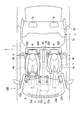
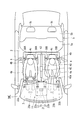
- FIGS. 1 and 2 show an air conditioning system 10A of the first embodiment.
- the vehicle 1 has an instrument panel 3 in the foremost part in the passenger compartment 2.
- two front seats (driver's seat and front passenger seat) 4 and one long rear seat 5 are provided.
- Each front seat 4 has a seat cushion 4a, a seat back 4b, and a headrest 4c.
- the rear seat 5 has a seat cushion 5a, a seat back 5b, and two headrests 5c.
- the air conditioning system 10A includes an air conditioning apparatus 11, suction ports 30A and 30B disposed around the front seat 4, and the suction ports 30A and 30B. And a sub duct 40 communicating with the main duct 13. An air passage is formed inside the main duct 13.
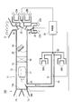
- the air conditioner 11 has an air conditioning unit 12 arranged inside the instrument panel 3. As shown in FIG. 3, a main duct 13 is provided in the air conditioning unit 12. The uppermost stream of the main duct 13 is provided with an outside air introduction port 14 for introducing air outside the vehicle compartment 2 (outside air) and an inside air introduction port 15 for introducing air inside the vehicle compartment 2 (inside air).
- the outside air introduction port 14 is opened and closed by an intake door 16a, and the inside air introduction port 15 is opened and closed by an intake door 16b.
- a blower 17 In the main duct 13, a blower 17, an evaporator (heat exchange unit) 18, and a heater core (heat exchange unit) 19 are arranged in this order from the upstream.
- the evaporator 18 is a cooling source
- the heater core 19 is a heating source.
- a mix door 20 is provided between the evaporator 18 and the heater core 19.
- the blower 17 rotates the fan and sucks the inside air and the outside air into the main duct 13.
- the evaporator 18 is arrange
- the heater core 19 is disposed in a substantially half area of the cross section of the main duct 13 and heats the air.
- the mix door 20 adjusts the ratio of the air volume that passes through the heater core 19 and the air volume that bypasses the heater core 19. By changing this air volume ratio, conditioned air at a desired temperature is generated.
- a defroster outlet 21, vent outlets 22a and 22b, and foot outlets 23a and 23b are provided downstream of the heater core 19, a defroster outlet 21, vent outlets 22a and 22b, and foot outlets 23a and 23b are provided.
- the defroster outlet 21 blows out the conditioned air to the windshield.
- the vent outlets 22a and 22b are composed of a vent outlet 22a in the driver's seat and a vent outlet 22b in the passenger seat, and blow out conditioned air to the upper body of the occupant.
- the foot air outlets 23a and 23b are composed of a foot air outlet 23a in the driver's seat and a foot air outlet 23b in the passenger seat, and blow out conditioned air to the lower body of the occupant.
- the defroster outlet 21 is opened and closed by a defroster door 24.
- the vent outlets 22a and 22b are opened and closed by a vent door 25.
- the foot outlets 23 a and 23 b are opened and closed by a foot door 26.
- a [served as a blow-out port selector] vent outlet selection door 60 provided as an outlet selector is located downstream of the vent door 25 in the main duct 13 and is on the driver side. It is arranged at a branch position between the outlet 22a and the passenger seat side vent outlet 22b.
- the vent outlet selection door 60 includes a driver seat side position for sending conditioned air to the driver seat side vent outlet 22a, a passenger seat side position for sending conditioned air to the passenger seat side vent outlet 22b, and a driver seat side vent outlet. It is possible to switch to an intermediate position for sending conditioned air to both 22a and the passenger seat side vent outlet 22b.
- a foot outlet selection door 61 provided as an outlet selector is arranged at a branch position between the driver seat side foot outlet 23a and the passenger seat side foot outlet 23b, downstream of the foot door 26 in the main duct 13.
- the foot outlet selection door 61 includes a driver seat side position for sending conditioned air to the driver seat side foot outlet 23a, a passenger seat side position for sending conditioned air to the passenger seat side foot outlet 23b, and a driver seat side foot outlet. It is possible to switch to an intermediate position for sending conditioned air to both the 23a and the passenger seat side foot outlet 23b.
- vent outlet selection door 60 and the foot outlet selection door 61 are controlled by a controller 50.
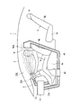
- the suction port 30A of the right front seat 4 (or the suction port 30B of the left front seat 4) is provided on both sides of the headrest 4c at the upper part of the seat back 4b. It has been. A total of four inlets 30 ⁇ / b> A and 30 ⁇ / b> B are opened immediately after the upper body of the occupant of the front seat 4.
- one end of the sub duct 40 is connected to the suction ports 30A and 30B.
- the other end of the sub duct 40 is connected to the main duct 13 upstream from the blower 17.
- a selection door 41 is arranged at a connection position of the sub duct 40 with the main duct 13.
- the selection door 41 can block communication between the inside of the sub duct 40 and the inside of the main duct 13.
- the operation of the selection door 41 is controlled by the control unit 50.
- a suction port selection door 62 provided as a suction port selector [suction port selector] is arranged at a confluence position between the driver seat side suction port 30A and the passenger seat side suction port 30B in the sub duct 40.
- the suction port selection door 62 includes a driver seat side position for sucking conditioned air from the driver seat side suction port 30A, a passenger seat side position for sucking conditioned air from the passenger seat side suction port 30B, and the driver seat side suction port 30A and the assistant. It is possible to switch to an intermediate position for sucking conditioned air from both of the seat side suction ports 30B.
- the suction port selection door 62 is controlled by the control unit 50.
- a temperature sensor S1 is arranged in the sub duct 40.
- the temperature sensor S1 detects the temperature of the conditioned air sucked from the suction ports 30A and 30B.
- the detection data of the temperature sensor S1 is output to the control unit 50.
- Various commands (settings) related to air conditioning are input to the operation panel (not shown).
- an overall air conditioning mode for air-conditioning the entire space of the passenger compartment 2 or a zone air conditioning mode for preferentially air-conditioning the front seat space can be selected.
- the zone air-conditioning mode three types of zones can be specified: the driver side, the passenger side, the driver side only, and the passenger side only.
- the control unit 50 controls the operation of the air conditioner 11 and the selection positions of the selection door 41, the vent outlet selection door 60, the foot outlet selection door 61, and the suction inlet selection door 62 according to a command from the operation panel. For example, when the overall air conditioning mode is selected, the control unit 50 sets the vent outlet selection door 60, the foot outlet selection door 61, and the inlet selection door 62 to the intermediate positions and closes the selection door 41, A temperature sensor (not shown) in the vicinity of the instrument panel 3 is used to control the blowout temperature of the conditioned air. On the other hand, when the zone air-conditioning mode is selected, the control unit 50 opens the selection door 41 and controls the air-conditioning air blowing temperature and the like using the temperature sensor S1 in the sub duct 40.
- the control unit 50 determines whether the vent air outlet selection door 60, the foot air outlet selection door 61, and the air inlet according to the designated area in the zone air-conditioning mode (driver seat side and passenger seat side, driver seat side only, passenger seat side only). The position of the selection door 62 is controlled.
- the operation of the above-described air conditioning system 10A will be described.
- air is sucked into the main duct 13 from the outside air inlet 14 and the inside air inlet 15 by the blower 17.
- the sucked air is converted into conditioned air at a desired temperature by the evaporator 18 and the heater core 19, and the conditioned air is supplied to the vehicle from at least one outlet 21, 22 a, 22 b, 23 a, 23 b (for example, vent outlet 22 a, 22 b). It is blown out into the chamber 2.
- the selection door 41 is closed. Thereby, the conditioned air is not sucked from the suction ports 30A and 30B. Therefore, the conditioned air blown into the passenger compartment 2 by the air conditioner 11 forms a flow that reaches almost the entire interior of the passenger compartment 2, and the entire passenger compartment 2 is air-conditioned.
- the selection door 41 is opened. Moreover, the suction inlet selection door 62, the vent blower outlet selection door 60, and the foot blower outlet selection door 61 are set to an intermediate position. Accordingly, as shown in FIG. 2, when the air-conditioning air blowing mode set in addition to the air-conditioning mode is the vent mode, the air-conditioning is performed from both the driver seat side vent air outlet 22a and the passenger seat side vent air outlet 22b. Wind is blown into the passenger compartment 2. On the other hand, when the blowing mode is the foot mode, conditioned air is blown into the passenger compartment 2 from both the driver's seat side foot outlet 23a and the passenger's seat side foot outlet 23b.
- the conditioned air blown into the passenger compartment 2 is sucked from both the driver seat side suction port 30A and the passenger seat side suction port 30B by the suction force of the blower 17.
- the sucked conditioned air is returned to the air conditioning unit 12 through the sub duct 40.
- the conditioned air flows intensively (preferentially) around the passenger on the driver's seat side front seat 4 and the passenger on the passenger seat side front seat 4 and is collected from the suction ports 30A and 30B.
- the flow of the conditioned air to the passenger compartment space behind the suction ports 30A and 30B is also suppressed. As a result, a zone air-conditioning region is formed around the driver seat side front seat 4 and the passenger seat side front seat 4 in the passenger compartment 2.
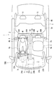
- the selection door 41 is opened. Moreover, the suction inlet selection door 62, the vent outlet selection door 60, and the foot outlet selection door 61 are set to the driver's seat side position. Thereby, as shown in FIG. 4, in the vent mode, the conditioned air is blown into the passenger compartment 2 only from the driver's seat side vent outlet 22a. On the other hand, in the foot mode, conditioned air is blown into the passenger compartment 2 only from the driver's seat side foot outlet 23a.
- the conditioned air blown into the passenger compartment 2 is sucked only from the driver seat side suction port 30 ⁇ / b> A by the suction force of the blower 17.
- the sucked conditioned air is returned to the air conditioning unit 12 through the sub duct 40.
- the conditioned air flows intensively (preferentially) around the passenger on the driver's seat side front seat 4 and is collected from the suction port 30A.
- the flow to the passenger compartment space behind the suction port 30A is also suppressed. As a result, a zone air-conditioning region is formed around the driver seat side front seat 4 in the passenger compartment 2.
- the suction selection door 41 is opened. Moreover, the suction inlet selection door 62, the vent outlet selection door 60, and the foot outlet selection door 61 are set to a passenger seat side position. Thus, as shown in FIG. 5, in the vent mode, the conditioned air is blown into the passenger compartment 2 only from the passenger seat side vent outlet 22b. On the other hand, in the foot mode, conditioned air is blown into the passenger compartment 2 only from the passenger seat side foot outlet 23b.
- the conditioned air blown into the passenger compartment 2 is sucked only from the passenger seat side suction port 30 ⁇ / b> B by the suction force of the blower 17.
- the sucked conditioned air is returned to the air conditioning unit 12 through the sub duct 40.
- the conditioned air flows intensively (preferentially) around the passenger on the passenger seat side front seat 4 and is collected from the inlet 30B.
- the flow to the passenger compartment space behind the suction port 30B is also suppressed. As a result, a zone air-conditioning region is formed around the front passenger seat 4 in the passenger compartment 2.
- the conditioned air at the desired temperature is generated using the evaporator 18 and the heater core 19 of the air conditioning unit 12.
- Installation of a dedicated heat exchange unit is not essential, and simplification and cost reduction of the system can be realized.
- the conditioned air sucked from the suction ports 30 ⁇ / b> A and 30 ⁇ / b> B flows through the sub duct 40 over the entire path returned to the air conditioner 11, and is returned to the air conditioner 11 while suppressing heat loss as much as possible. As a result, the air conditioning load of the air conditioner 11 is reduced.
- the suction port selection door 62 can select from which of the suction ports 30A and 30B (including both) the conditioned air is sucked, the zone air conditioning region can be variably controlled as described above.
- the system configuration can be simplified and the cost can be reduced.
- immediate cooling and immediate warming are improved by zone air conditioning.
- the above embodiment can be realized simply by installing the suction ports 30A and 30B, the sub duct 40, etc., and retrofit installation can be easily performed.
- the entire air conditioning mode and the zone air conditioning mode can be selectively executed by the selection door 41. Moreover, it is possible to easily switch between the overall air conditioning mode and the zone air conditioning mode simply by controlling the operation of the selection door 41.
- the suction of air-conditioned air is selected from either the driver seat side suction port 30A and the passenger seat side suction port 30B, or either the driver seat side suction port 30A or the passenger seat side suction port 30B by the suction port selection door 62. Done. Therefore, in the zone air-conditioning mode, one area can be selected from the three zone air-conditioning areas (driver seat side and passenger seat side, driver seat side only, passenger seat side only).
- the suction inlet and the outlet (operating) corresponding to each other by the inlet selector (suction inlet selection door 62) and the outlet selector (the vent outlet selecting door 60 or the foot outlet selecting door 61).
- the seat side suction port 30A and the driver seat vent outlet 22a or the driver seat foot outlet 23a: the passenger seat side inlet 30B and the passenger seat side vent outlet 22b or the passenger seat side foot outlet 23b) are interlocked. Can be selected. Therefore, the blowing of the conditioned air that does not contribute to the zone air conditioning from the air conditioning unit 12 is suppressed, and only the conditioned air that effectively contributes to the zone air conditioning is blown out from the air conditioning unit 12. As a result, the air conditioning load of the air conditioner 11 is further reduced, and energy saving can be realized.
- the conditioned air can be sucked from the suction ports 30A and 30B by using the suction force of the blower 17. For this reason, it is not necessary to separately provide a blower only for suction from the suction ports 30A and 30B. As a result, further simplification and cost reduction of the system configuration can be realized.
- the suction ports 30A and 30B are provided in the front seat 4.
- the front seat 4 is an existing component that is always provided, and is most suitable for disposing the suction ports 30A and 30B, and the suction ports 30A and 30B are easy to install.
- the suction ports 30A and 30B are provided in the upper part of the seat back 4b. Airflows of conditioned air (warm air, cold air) blown out from the vent outlets 22a and 22b are likely to gather above the passenger compartment 2 without a shield. Therefore, the conditioned air can be efficiently sucked by the suction ports 30A and 30B provided in the upper part of the seat back 4b, and the recovery rate of the conditioned air is improved.
- conditioned air warm air, cold air
- a temperature sensor S1 for detecting the temperature of the conditioned air sucked from the suction ports 30A and 30B is provided. Therefore, in the zone air-conditioning mode, the temperature of the air-conditioning air blown from the air conditioner 11 can be controlled based on the temperature of the air-conditioning air that has actually passed around the passenger, and the air-conditioning temperature can be accurately controlled.
- FIGS. 6 and 7 show an air conditioning system 10B of the second embodiment.
- the connection position of the other end of the sub-duct 40 is different from the air conditioning system 10A of the first embodiment described above.
- the other end of the sub duct 40 is connected to the main duct 13 between the blower 17 and the evaporator 18.
- the sub duct 40 is provided with a sub blower 42 that sucks air from the suction ports 30A and 30B.
- the sub blower 42 is controlled by the control unit 50.
- the operation of the air conditioning system 10B described above will be described.
- air is sucked into the main duct 13 from the outside air inlet 14 and the inside air inlet 15 by the blower 17.
- the sucked air is converted into conditioned air at a desired temperature by the evaporator 18 and the heater core 19, and the conditioned air is supplied to the vehicle from at least one outlet 21, 22 a, 22 b, 23 a, 23 b (for example, vent outlet 22 a, 22 b). It is blown out into the chamber 2.
- the selection door 41 is closed and the sub blower 42 is not driven. Thereby, the conditioned air is not sucked from the suction ports 30A and 30B. Therefore, the conditioned air blown into the passenger compartment 2 by the air conditioner 11 forms a flow that reaches almost the entire interior of the passenger compartment 2, and the entire passenger compartment 2 is air-conditioned.
- the selection door 41 is opened and the sub-blower 42 is driven. Accordingly, the conditioned air is sucked from the suction ports 30 ⁇ / b> A and 30 ⁇ / b> B by the suction force of the sub blower 42. Therefore, the conditioned air blown into the passenger compartment 2 from the air conditioner 11 is sucked from both the driver seat side suction port 30A and the passenger seat side suction port 30B. The sucked conditioned air is returned to the air conditioning unit 12 through the sub duct 40. The conditioned air flows intensively (preferentially) around the passenger on the front seat 4 and is collected by the suction ports 30A and 30B. The flow of conditioned air to the passenger compartment space behind the suction ports 30A and 30B is also suppressed. As a result, a zone air-conditioning area is formed around the front seat 4 in the passenger compartment 2.
- the vent outlet selection door 60, the foot outlet selection door 61, and the inlet selection is controlled, and a flow of conditioned air similar to that of the first embodiment is formed.
- the air conditioning system 10B simplification of the system configuration and cost reduction can be realized as in the first embodiment.
- comfortable zone air conditioning can be performed while realizing energy saving by reducing the air conditioning load.
- immediate cooling and immediate warming are improved by zone air conditioning.
- the zone air-conditioning area can be easily variably controlled.
- the entire air conditioning mode and the zone air conditioning mode can be selectively executed by controlling the selection door 41 and the sub blower 42.
- the suction amount of the suction ports 30A and 30B can be adjusted independently of the blow amount of the air conditioner 11.
- FIGS. 8 to 10 show an air conditioning system 10C of the third embodiment.
- the air conditioning system 10C is different from the air conditioning system 10A of the first embodiment described above in that the sub duct 40 is not directly connected to the main duct 13.
- the sub duct 40 is provided with the sub blower 42 described in the second embodiment, and the auxiliary internal air introduction port 27 is provided near the internal air introduction port 15 of the main duct 13. Is also different from the air conditioning system 10A of the first embodiment described above.
- the other end of the duct 40 is not connected to the air conditioning unit 12.
- the opening 40 a at the other end of the duct 40 is opened toward the inside air introduction port 15 and the auxiliary room air introduction port 27 in the vicinity of the room air introduction port 15 and the auxiliary room air introduction port 27 of the air conditioning unit 12. Therefore, in this embodiment, the selection door 41 of 1st Embodiment is not provided, but the sub air blower 42 demonstrated in 2nd Embodiment is provided instead.
- the sub blower 42 is controlled by the control unit 50.
- the sub blower 42 In the overall air conditioning mode, the sub blower 42 is not driven. Thereby, the conditioned air is not sucked from the suction ports 30A and 30B. Therefore, the conditioned air blown into the passenger compartment 2 by the air conditioner 11 forms a flow that spreads over almost the entire interior of the passenger compartment 2, and the entire passenger compartment 2 is air-conditioned.
- the sub blower 42 In the zone air conditioning mode (driver seat side and passenger seat side), the sub blower 42 is driven. Accordingly, the conditioned air is sucked from the suction ports 30 ⁇ / b> A and 30 ⁇ / b> B by the suction force of the sub blower 42. Therefore, the conditioned air blown into the passenger compartment 2 from the air conditioner 11 is sucked from both the driver seat side suction port 30A and the passenger seat side suction port 30B. The sucked conditioned air is blown out from the opening 40a near the air conditioning unit 12 through the sub duct 40, and immediately after that, is sucked into the air conditioning unit 12 from the inside air introduction port 15 or the auxiliary inside air introduction hole 27.
- the air blown from the opening 40a is sucked into the air conditioning unit 12 from the inside air introduction port 15.
- the auxiliary inside air inlet 27 is closed by the auxiliary suction door 28.
- the air blown from the opening 40 a is sucked into the air conditioning unit 12 from the auxiliary inside air introduction port 27.
- the auxiliary inside air inlet 27 is opened by the auxiliary suction door 28.
- the conditioned air flows intensively (preferentially) around the passenger on the front seat 4 and is collected from the suction ports 30A and 30B.
- the flow to the passenger compartment space behind the suction ports 30A and 30B is also suppressed.
- a zone air-conditioning area is formed around the front seat 4 in the passenger compartment 2.
- the vent outlet selection door 60, the foot outlet selection door 61, and the inlet selection is controlled, and a flow of conditioned air similar to that of the first embodiment is formed.
- zone air-conditioning mode air-conditioning air having a desired temperature is generated using the evaporator 18 and the heater core 19 of the air-conditioning unit 12, so that it is not essential to install a heat exchanging unit dedicated to zone air-conditioning, simplifying the system and reducing the cost. Can be realized.
- the conditioned air sucked from the suction ports 30 ⁇ / b> A and 30 ⁇ / b> B flows through the sub duct 40 in most of the path returned to the air conditioner 11, and is returned to the air conditioner 11 while suppressing heat loss as much as possible. As a result, the air conditioning load of the air conditioner 11 is reduced.
- the suction port selection door 62 can select from which of the suction ports 30A and 30B (including both) the conditioned air is sucked, the zone air conditioning region can be variably controlled as described above.
- the system configuration can be simplified and the cost can be reduced.
- immediate cooling and immediate warming are improved by zone air conditioning.
- the above embodiment can be realized simply by installing the suction ports 30A and 30B, the sub duct 40, the sub blower 42, and the like, and retrofit installation can be easily performed.
- the entire air conditioning mode and the zone air conditioning mode can be selectively performed, and the switching can be easily controlled.
- the opening 40a of the sub duct 40 is disposed in the vicinity of the inside air introduction port 15 (auxiliary inside air introduction hole 27) of the air conditioning unit 12, and is opened toward the inside air introduction port 15 (auxiliary inside air introduction hole 27). Yes. Therefore, the air blown out from the opening 40a is reliably and quickly collected in the air conditioning unit 12 by the synergistic action of the suction force of the blower 17 of the air conditioning unit 12 and the blowing output of the sub blower 42 of the sub duct 40.
- the air conditioning unit 12 has an auxiliary inside air inlet 27 and an auxiliary suction door 28. Therefore, since the air blown from the opening 40a can be collected in the air conditioning unit 12 by the auxiliary inside air introduction port 27, zone air conditioning can be performed even when outside air is introduced.
- the auxiliary air inlet 27 is provided in the main duct 13 of the air conditioning unit 12 and the auxiliary air inlet 27 for opening and closing the auxiliary air inlet 27 is provided, but the auxiliary air inlet 27 and the auxiliary air door 28 are provided. It may not be provided.
- the intake doors 16a and 16b are controlled to open both the outside air introduction port 14 and the inside air introduction port 15. In this way, it is not necessary to provide the auxiliary inside air inlet 27 and the auxiliary suction door 28, and the system configuration can be simplified.
- the suction amount of the suction ports 30A and 30B can be adjusted independently of the blow amount of the air conditioner 11.
- zone air conditioning can be performed for the passenger on the front seat 4 and the zone air conditioning area is set for each of the passenger on the driver side front seat 4 and the passenger on the passenger side front seat 4. it can. Furthermore, zone air conditioning may be set for each of the passengers on the right rear seat 5 and the passengers on the left rear seat 5, and the zone air conditioning may be performed for the passengers on the rear seat 5. That is, in this modified example, in addition to the configuration of any of the first to third embodiments, a plurality of suction openings opened around the rear seat 5 and conditioned air from these suction openings are air-conditioned.
- the apparatus includes a sub duct, and the sub duct for the rear seat 5 includes a suction port selection door. According to this configuration, the zone air conditioning region can be set not only for the passenger on the front seat 4 but also for the passenger on the rear seat 5. This modification is particularly effective for a vehicle having a large volume of the passenger compartment 2 such as a one-box car.
- the suction ports 30A to 30D are provided in the seat 4 or 5, but may be provided anywhere around the occupant's seat. Providing the suction ports 30A to 30D around the seat 4 or 5 is easy to install later.
- the zone air conditioning region may be set based on a manual operation, or may be automatically set based on a detection result of an occupant detector (for example, a seating sensor).
- an occupant detector for example, a seating sensor
Landscapes
- Physics & Mathematics (AREA)
- Thermal Sciences (AREA)
- Engineering & Computer Science (AREA)
- Mechanical Engineering (AREA)
- Air-Conditioning For Vehicles (AREA)
Abstract
La présente invention concerne un système de conditionnement d'air de véhicule comportant comme suit : un dispositif de conditionnement d'air qui comporte une soufflante principale, une conduite principale, et une unité d'échange de chaleur et qui est configuré de sorte que l'air aspiré dans la conduite principale par la soufflante d'air est converti en air conditionné souhaité par l'unité d'échange de chaleur et est ensuite envoyé par soufflage à l'intérieur du véhicule ; une pluralité d'admissions disposées sur la périphérie du siège de passager ; une sous-conduite, dont une extrémité est raccordée à la pluralité d'admissions, qui peut aspirer l'air conditionné en provenance de la pluralité d'admissions et le renvoyer dans le dispositif de conditionnement d'air ; et un dispositif de sélection d'admission qui sélectionne parmi la pluralité d'admissions au moins une admission devant servir à aspirer l'air conditionné. Avec un tel système de conditionnement d'air, il est possible de simplifier et de réduire les coûts du système, d'effectuer un conditionnement d'air de zone confortable qui permet de réduire la consommation d'énergie par une réduction de la charge de conditionnement d'air, et de régler facilement les régions de conditionnement d'air de zone.
Applications Claiming Priority (2)
| Application Number | Priority Date | Filing Date | Title |
|---|---|---|---|
| JP2011-116683 | 2011-05-25 | ||
| JP2011116683A JP2012245804A (ja) | 2011-05-25 | 2011-05-25 | 車両用空気調和システム |
Publications (1)
| Publication Number | Publication Date |
|---|---|
| WO2012161145A1 true WO2012161145A1 (fr) | 2012-11-29 |
Family
ID=47217222
Family Applications (1)
| Application Number | Title | Priority Date | Filing Date |
|---|---|---|---|
| PCT/JP2012/062887 Ceased WO2012161145A1 (fr) | 2011-05-25 | 2012-05-21 | Système de conditionnement d'air de véhicule |
Country Status (2)
| Country | Link |
|---|---|
| JP (1) | JP2012245804A (fr) |
| WO (1) | WO2012161145A1 (fr) |
Families Citing this family (1)
| Publication number | Priority date | Publication date | Assignee | Title |
|---|---|---|---|---|
| WO2018047463A1 (fr) * | 2016-09-08 | 2018-03-15 | 株式会社デンソー | Système de climatisation pour véhicule |
Citations (3)
| Publication number | Priority date | Publication date | Assignee | Title |
|---|---|---|---|---|
| JPH05301516A (ja) * | 1992-04-24 | 1993-11-16 | Nippondenso Co Ltd | 座席用空調装置 |
| JP2000289436A (ja) * | 1999-04-09 | 2000-10-17 | Mitsubishi Heavy Ind Ltd | 車両用空気調和装置 |
| JP2010076591A (ja) * | 2008-09-25 | 2010-04-08 | Panasonic Electric Works Co Ltd | 車載用空気調和装置 |
Family Cites Families (1)
| Publication number | Priority date | Publication date | Assignee | Title |
|---|---|---|---|---|
| FR2824298B1 (fr) * | 2001-05-04 | 2003-12-12 | Valeo Climatisation | Dispositif de recyclage de l'air d'un habitacle de vehicule |
-
2011
- 2011-05-25 JP JP2011116683A patent/JP2012245804A/ja not_active Withdrawn
-
2012
- 2012-05-21 WO PCT/JP2012/062887 patent/WO2012161145A1/fr not_active Ceased
Patent Citations (3)
| Publication number | Priority date | Publication date | Assignee | Title |
|---|---|---|---|---|
| JPH05301516A (ja) * | 1992-04-24 | 1993-11-16 | Nippondenso Co Ltd | 座席用空調装置 |
| JP2000289436A (ja) * | 1999-04-09 | 2000-10-17 | Mitsubishi Heavy Ind Ltd | 車両用空気調和装置 |
| JP2010076591A (ja) * | 2008-09-25 | 2010-04-08 | Panasonic Electric Works Co Ltd | 車載用空気調和装置 |
Also Published As
| Publication number | Publication date |
|---|---|
| JP2012245804A (ja) | 2012-12-13 |
Similar Documents
| Publication | Publication Date | Title |
|---|---|---|
| JP4224939B2 (ja) | 車両用空調装置 | |
| KR101745139B1 (ko) | 공조기 연동 시트 장치 | |
| JP2001055037A (ja) | 車両用空調装置 | |
| JP2014180985A (ja) | 車両用空気調和システム | |
| WO2021075258A1 (fr) | Système de climatisation de véhicule automobile | |
| JP2014141236A (ja) | 車両用空気調和システム | |
| JP2015104980A (ja) | 車両用空調システム | |
| WO2012077670A1 (fr) | Système de climatisation pour véhicule | |
| KR20100065599A (ko) | 차량용 공조장치의 에어 커튼 시스템 | |
| JP4333512B2 (ja) | 車両用空調装置 | |
| JP2013147061A (ja) | 車両用空調装置 | |
| JP2008149998A (ja) | 車両用空調装置 | |
| WO2014103610A1 (fr) | Système de conditionnement d'air pour véhicule | |
| KR101648226B1 (ko) | 차량 후석용 보조 냉난방장치 | |
| KR20100006962A (ko) | 차량용 공조장치의 시트 냉난방장치 | |
| WO2012161145A1 (fr) | Système de conditionnement d'air de véhicule | |
| JP2009286169A (ja) | 車両用空調装置 | |
| JP5062523B2 (ja) | 自動車用シート空調装置 | |
| JP2014196028A (ja) | 車両用空気調和システム | |
| JP2012121482A (ja) | 車両用空気調和システム | |
| WO2018003307A1 (fr) | Appareil de soufflage d'air destiné à des sièges | |
| JP5761952B2 (ja) | 車両用空調装置 | |
| KR101151934B1 (ko) | 차량용 시트 공조장치 | |
| JPH106744A (ja) | ワンボックス車用の空気調和装置 | |
| JP2770531B2 (ja) | バス用空調ダクト |
Legal Events
| Date | Code | Title | Description |
|---|---|---|---|
| 121 | Ep: the epo has been informed by wipo that ep was designated in this application |
Ref document number: 12789541 Country of ref document: EP Kind code of ref document: A1 |
|
| NENP | Non-entry into the national phase |
Ref country code: DE |
|
| 122 | Ep: pct application non-entry in european phase |
Ref document number: 12789541 Country of ref document: EP Kind code of ref document: A1 |