WO2012161484A2 - 실리콘화합물을 이용하여 제조된 마그네슘계 합금 및 그 제조 방법 - Google Patents
실리콘화합물을 이용하여 제조된 마그네슘계 합금 및 그 제조 방법 Download PDFInfo
- Publication number
- WO2012161484A2 WO2012161484A2 PCT/KR2012/003964 KR2012003964W WO2012161484A2 WO 2012161484 A2 WO2012161484 A2 WO 2012161484A2 KR 2012003964 W KR2012003964 W KR 2012003964W WO 2012161484 A2 WO2012161484 A2 WO 2012161484A2
- Authority
- WO
- WIPO (PCT)
- Prior art keywords
- magnesium
- silicon compound
- molten metal
- alloy
- silicon
- Prior art date
- Legal status (The legal status is an assumption and is not a legal conclusion. Google has not performed a legal analysis and makes no representation as to the accuracy of the status listed.)
- Ceased
Links
Images




Classifications
-
- C—CHEMISTRY; METALLURGY
- C22—METALLURGY; FERROUS OR NON-FERROUS ALLOYS; TREATMENT OF ALLOYS OR NON-FERROUS METALS
- C22B—PRODUCTION AND REFINING OF METALS; PRETREATMENT OF RAW MATERIALS
- C22B26/00—Obtaining alkali, alkaline earth metals or magnesium
- C22B26/20—Obtaining alkaline earth metals or magnesium
- C22B26/22—Obtaining magnesium
-
- B—PERFORMING OPERATIONS; TRANSPORTING
- B22—CASTING; POWDER METALLURGY
- B22D—CASTING OF METALS; CASTING OF OTHER SUBSTANCES BY THE SAME PROCESSES OR DEVICES
- B22D21/00—Casting non-ferrous metals or metallic compounds so far as their metallurgical properties are of importance for the casting procedure; Selection of compositions therefor
- B22D21/02—Casting exceedingly oxidisable non-ferrous metals, e.g. in inert atmosphere
- B22D21/04—Casting aluminium or magnesium
-
- C—CHEMISTRY; METALLURGY
- C22—METALLURGY; FERROUS OR NON-FERROUS ALLOYS; TREATMENT OF ALLOYS OR NON-FERROUS METALS
- C22B—PRODUCTION AND REFINING OF METALS; PRETREATMENT OF RAW MATERIALS
- C22B9/00—General processes of refining or remelting of metals; Apparatus for electroslag or arc remelting of metals
- C22B9/10—General processes of refining or remelting of metals; Apparatus for electroslag or arc remelting of metals with refining or fluxing agents; Use of materials therefor, e.g. slagging or scorifying agents
-
- C—CHEMISTRY; METALLURGY
- C22—METALLURGY; FERROUS OR NON-FERROUS ALLOYS; TREATMENT OF ALLOYS OR NON-FERROUS METALS
- C22C—ALLOYS
- C22C23/00—Alloys based on magnesium
Definitions
- the present invention relates to a magnesium-based alloy prepared by directly adding a silicon compound instead of silicon to a molten magnesium or magnesium alloy, and a method of manufacturing the same. More specifically, a magnesium alloy in which a silicon compound is introduced into a molten magnesium or a magnesium alloy to induce a reduction reaction of the silicon compound in the molten metal, and the silicon produced by the reduction reaction is compounded in the molten metal and a method for preparing the same. will be.
- magnesium or magnesium alloy is the lightest metal among practical metals, and is expected to be a lightweight structural material because of its excellent strength and specific strength.
- magnesium alloys are alloyed by adding alloying elements other than compounds to magnesium or magnesium alloys.
- An object of the present invention is to provide a magnesium-based alloy prepared by a new method and a method for producing the same by adding a silicon compound to the magnesium or magnesium alloy molten metal.
- Another object of the present invention is to reduce the manufacturing cost of the alloy by using a relatively low-cost silicon compound (SiO 2 ) instead of silicon (Si) added to the existing magnesium or magnesium alloy.
- Yet another object of the present invention is to maximize the effect of the additive alloy element by minimizing the solid solution of silicon by indirectly adding a silicon compound, instead of adding silicon directly.
- Still another object of the present invention is to maximize the amount of silicon compound produced in magnesium or magnesium alloy to increase the physical properties of the magnesium alloy.
- Magnesium-based alloy manufacturing method of the present invention for achieving the above object is a step of dissolving magnesium or magnesium alloy in the liquid phase, adding a silicon compound to the molten magnesium or magnesium alloy is dissolved, the molten silicon and the added silicon Reacting at least a portion of the silicon compound in the magnesium or magnesium alloy through reaction of a compound, and reacting at least a portion of the silicon resulting from the exhaustion in the magnesium or magnesium alloy.
- Magnesium-based alloy manufacturing method of the present invention dissolving the magnesium or magnesium alloy in the liquid phase, adding a silicon compound to the molten magnesium or magnesium alloy is dissolved, the sufficient reaction of the molten metal and the added silicon compound Through this, exhausting the silicon compound so that it does not substantially remain in the magnesium alloy, and reacting the silicon resulting from the exhaustion so as not to substantially remain in the magnesium or magnesium alloy.
- the method may further include spreading the silicon compound evenly on the surface of the molten metal so as not to be mixed into the molten metal.
- the oxygen element of the silicon compound may be removed in the form of oxygen gas or in the form of a dross through a combination of magnesium and / or alloying elements of magnesium in the molten metal.
- reaction between the molten metal and the added silicon compound is characterized in that by promoting the stirring of the molten metal.
- the silicon produced as a result of exhaustion forms a compound with at least one of magnesium in the magnesium alloy and other alloying elements, and is substantially free of residual silicon.
- the silicon compound is characterized in that the powder state to promote the reaction with the magnesium or magnesium alloy.
- the silicon compound is sufficiently reacted with the molten metal of the magnesium or magnesium alloy is exhausted and characterized in that it is added to the amount that can not remain as the silicon compound in the molten metal.
- the stirring is performed by electromagnetic stirring of the molten metal or by mechanically stirring the molten metal.
- the stirring is characterized in that the molten surface is performed in the state exposed to the atmosphere, the compound is Mg 2 Si.
- the silicon compound is characterized in that the particle size of 0.1 to 200 ⁇ m, the addition amount of the silicon compound is 0.001% by weight to 30% by weight.
- Magnesium-based alloy manufacturing method of the present invention comprises the steps of dissolving the magnesium or magnesium alloy in the liquid phase, adding a silicon compound to the molten magnesium or magnesium alloy is dissolved, through the reduction reaction of the molten metal and the added silicon compound Removing the oxygen element of the silicon compound, and compounding the silicon produced by the reduction reaction in the molten metal.
- Magnesium-based alloy of the present invention for achieving the above object is formed through the manufacturing method as described above.
- the present invention can solve the problems caused by the direct addition of silicon as a new magnesium-based alloy by adding a silicon compound to the magnesium or magnesium alloy molten metal.
- a silicon compound to be added can be purchased at a lower cost than silicon in the manufacturing process of a magnesium-based alloy, thereby reducing the production cost of the magnesium alloy.
- silicon produced by the reduction reaction from the added silicon compound is not dissolved in the magnesium alloy, but directly forms a phase of the compound (typically Mg 2 Si).
- the amount of silicon in the silicon compound can be used to predict the amount of silicon to be included as an image formation in the magnesium alloy.
- the structure of the magnesium alloy due to the phase formation of the compound is refined to improve the mechanical properties.
- the silicon element supplied to the molten metal through the reduction reaction of the silicon compound is combined with the magnesium element of the molten metal or other alloying elements to form a high temperature stable compound.
- the compound thus produced helps to improve the properties of the magnesium alloy.
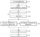
- FIG. 1 is a flowchart illustrating a method of manufacturing a magnesium alloy according to the present invention.
- FIG. 2 is a flowchart illustrating dissociation of silicon oxide added to the molten magnesium in the present invention.
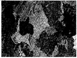
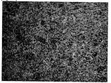
- FIG 3 is a structure photograph ( ⁇ 50) of a magnesium alloy prepared by adding 0.5 wt% SiO 2 to Mg according to the present invention.
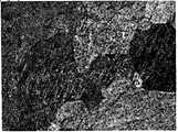
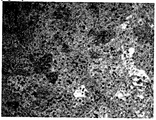
- FIG 4 is a structure photograph ( ⁇ 100) of a magnesium alloy prepared by adding 0.5 wt% SiO 2 to Mg according to the present invention.
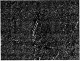
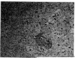
- FIG 5 is a structure photograph ( ⁇ 200) of a magnesium alloy prepared by adding 0.5 wt% SiO 2 to Mg according to the present invention.
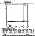
- FIG. 6 is a graph showing point analysis of EPMA of magnesium alloy prepared by adding 0.5 wt% SiO 2 to Mg according to the present invention.
- FIG. 9 is a photograph showing mapping analysis of silicon (Si) of a magnesium alloy prepared by adding 0.5 wt% SiO 2 to Mg according to the present invention.
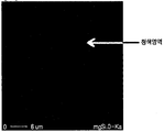
- FIG 10 is a photograph showing a mapping analysis for oxygen (O) of the magnesium alloy prepared by adding 0.5wt% SiO 2 to Mg according to the present invention.
- FIG 11 is a structure photograph ( ⁇ 50) of a magnesium alloy prepared by adding 0.5 wt% SiO 2 to an Mg alloy (AM60) according to the present invention.
- FIG. 12 is a structure photograph ( ⁇ 100) of a magnesium alloy prepared by adding 0.5 wt% SiO 2 to an Mg alloy (AM60) according to the present invention.
- FIG. 13 is a structure photograph ( ⁇ 200) of a magnesium alloy prepared by adding 0.5 wt% SiO 2 to an Mg alloy (AM60) according to the present invention.
- FIG. 14 is a graph showing a point analysis of EPMA of a magnesium alloy prepared by adding 0.5 wt% SiO 2 to an Mg alloy (AM60) according to the present invention.
- Mg magnesium
- AM60 Mg alloy
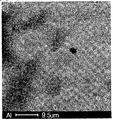
- FIG. 16 is a photograph showing mapping analysis of aluminum (Al) of a magnesium alloy prepared by adding 0.5 wt% SiO 2 to an Mg alloy (AM60) according to the present invention.
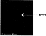
- FIG. 17 is a photograph showing mapping analysis of silicon (Si) of a magnesium alloy prepared by adding 0.5 wt% SiO 2 to an Mg alloy (AM60) according to the present invention.
- FIG. 18 is a photograph showing mapping analysis of oxygen (O) of a magnesium alloy prepared by adding 0.5 wt% SiO 2 to an Mg alloy (AM60) according to the present invention.
- the present invention relates to a method for producing a new alloy by adding a silicon compound to a molten magnesium or magnesium alloy, and an alloy thereof.
- FIG. 1 is a flowchart illustrating a method of manufacturing a magnesium-based alloy according to the present invention.
- a method of manufacturing a magnesium-based alloy according to the present invention includes forming a molten magnesium (S1), adding a silicon compound (S2), stirring (S3), and exhausting a silicon compound ( S4), a reaction step (S5) of the molten metal and the silicon, a casting step (S6), and a solidification step (S7).
- the exhausting step (S4) of the silicon compound and the reaction step (S5) of the melt and the produced silicon are separated into separate steps for convenience of description, but the two processes (S4, S5) occur almost simultaneously.
- S4 and S5 may occur substantially before the stirring step of S3.
- S4 and S5 may occur simultaneously with the addition of the silicon compound.
- magnesium or a magnesium alloy is placed in a crucible and provided with a temperature of 400 to 800 ° C. in a protective gas atmosphere. Then, the magnesium alloy in the crucible is dissolved to form a magnesium molten metal.
- the temperature for dissolving the magnesium or magnesium alloy means the temperature at which the pure magnesium metal melts and the temperature at which the magnesium alloy melts.
- the melting temperature may vary depending on the type of alloy.
- silicon compound is added while magnesium or magnesium alloy is completely dissolved.
- the melting temperature of magnesium or magnesium alloy is sufficient to be a temperature at which the solid phase is sufficiently melted and is present in a complete liquid phase.
- the silicon compound may be heated to a predetermined temperature and added to the molten metal.
- the temperature is less than 400 °C magnesium alloy molten metal is difficult to form, if the temperature exceeds 800 °C there is a risk that the magnesium-based molten metal is ignited.
- the melting point is often lowered.
- Magnesium used in the magnesium-based molten metal forming step may be any one selected from pure magnesium, magnesium alloy, and equivalents thereof.
- magnesium alloys are AZ91D, AM20, AM30, AM50, AM60, AZ31, AS41, AS31, AS21X, AE42, AE44, AX51, AX52, AJ50X, AJ52X, AJ62X, MRI153, MRI230, AM-HP2,
- Magnesium-Al, Magnesium It may be any one selected from -Al-Re, magnesium-Al-Sn, magnesium-Zn-Sn, magnesium-Si, magnesium-Zn-Y and equivalents thereof.
- any magnesium alloy used in the industry can be used.
- a silicon compound in powder form is added to the magnesium molten metal.
- the silicon compound is preferably in a powder state in order to promote the reaction with the magnesium alloy.
- the silicon compound added for the reaction may be added in any form. It is preferable to add powder in order to increase the reaction surface area for efficient reaction. However, if it is too fine, less than 0.1 ⁇ m it is difficult to be injected into the furnace is scattered by the evaporated magnesium or hot air. Then, they coagulate with each other and become agglomerated without easily mixing with the molten metal in the liquid phase. If too thick, it is not preferable from the viewpoint of increasing the surface area. It is preferable that the particle size of an ideal powder shall be 500 micrometers or less. More preferably, it is 200 micrometers or less.
- SiO 2 As the silicon compound added to the molten metal, SiO 2 may be typically used. However, the silicon compound of any kind may be used without being limited to SiO 2 .
- the amount of silicon compound used in the step of adding the silicon compound depends on the amount of magnesium or magnesium molten metal.
- the amount of silicon compound that can be added by reaction in the molten metal can be added up to the amount that the silicon compound is exhausted and does not remain as a silicon compound in the final magnesium alloy.
- the silicon compound may be added to an amount that does not remain in the molten metal of the magnesium or magnesium alloy. If an excessive amount of silicon compound is added, it is removed together with the dross of the molten metal or after the tapping. Through experiments, it was confirmed that the silicon compound was easily reduced in the molten metal when added to 30 wt% of the molten metal. The addition of less than 0.001 silicon compound by weight was weak to obtain the effect of alloying.
- the input amount of the silicon compound is determined according to the final target alloy composition desired.
- the amount of silicon compound can be determined by inversely calculating the amount of silicon alloyed in the magnesium alloy.
- stirring step (S3) is stirred for 1 second to 60 minutes per 0.1wt% of the silicon compound added to the magnesium or magnesium alloy molten metal.
- the stirring time is less than 1 second per 0.1 wt%, the compound does not sufficiently react to the magnesium molten metal. If the stirring time exceeds 60 minutes per 0.1 wt%, the stirring time of the magnesium molten metal may be unnecessarily longer. In general, the time for stirring depends on the size of the molten metal and the amount of silicon compound introduced.
- the addition of the required amount of the compound powder may be performed at a time, the method may be used. However, in order to accelerate the reaction and lower the possibility of aggregation of the powder, it is also preferable to sequentially add the compound powder again or by dividing it in an appropriate amount with a time difference. This can lead to reactions occurring mainly on the surface.
- Stirring is preferred for efficient reduction of the magnesium or magnesium alloy of the invention with the silicon compound.
- a device capable of applying an electromagnetic field around the furnace containing the molten metal may generate an electromagnetic field to induce convection of the molten metal.
- artificial stirring mechanical stirring
- the silicon compound powder to be introduced may be appropriately stirred so as not to agglomerate. The ultimate purpose of the agitation is to adequately induce the reaction of the melt with the injected powder.
- the time for the stirring may be different depending on the temperature of the molten metal and the state of the silicon compound powder (preheated state).
- the stirring is performed until no silicon compound powder is visible on the surface of the molten metal. It is preferable to stir until the molten metal and the silicon compound cause a sufficient reaction.
- sufficient reaction means a state in which the silicon compound is exhausted by substantially all reduction reactions with the molten metal.
- the specific gravity of the silicon compound is greater than that of magnesium or magnesium alloy.
- the silicon compound sinks into the molten magnesium or magnesium alloy.
- the viscosity of the molten metal is larger than the influence of the specific gravity of the powder, so that it is more likely to float on the surface of the molten metal without falling below the molten metal.
- the compound in the form of a powder is used, it can be said that the agitation of the compound is performed in the upper portion. In the case of the compound remaining precipitated by the specific gravity difference can be removed by adjusting the alloy during tapping.
- the silicon compound to be added to the surface of the molten metal may promote the reaction through stirring. That is, the reaction in the molten metal as well as the reaction in the molten metal can be induced to maximize the reduction of the silicon compound.
- the present invention it is important to create a reaction environment so that the compound reacts on the surface of the melt rather than reacting in the melt. To do this, it is important not to force the compound suspended on the surface of the melt into the melt. That is, when the injected silicon compound is mixed into the molten metal without floating in the upper portion of the molten metal, a reduction reaction in which oxygen is separated from the silicon compound does not easily occur. It is important to simply spread the compound on the surface so that it spreads evenly across the surface of the melt.
- the reaction was better to do the reaction rather than to agitate, and it was better to stir on the outer surface (upper surface) than on the inside of the molten metal. That is, the outer surface (top surface) reacted better with the atmosphere and the exposed powder.
- the contact of the molten metal in the air was better for the reduction reaction.
- the silicon compound has many opportunities for reaction on the surface of the molten metal by adding an appropriate amount sequentially in consideration of the surface area of the molten metal rather than adding excessive amounts of the silicon compound at the same time.
- Oxygen components of the silicon compound are substantially removed over the surface of the molten metal by stirring the upper layer of the molten metal.
- the agitation may be performed at an upper layer of about 20% of the total depth of the molten metal from the molten surface. At a depth of 20% or more, the surface reactions presented as preferred examples in the present invention are difficult to occur. More preferably, the stirring is performed at the upper layer part of about 10% of the total depth of the molten metal from the molten surface. This could minimize the disturbance of the molten metal by inducing the floating silicon compound to actually be located 10% above the depth of the molten metal.
- the silicon compound (S4) In the exhausting of the silicon compound (S4), the silicon compound is exhausted so as not to remain at least partly or substantially in the magnesium alloy through the reaction of the molten metal and the added silicon compound.
- the silicon compound introduced in the present invention is preferably exhausted by the reduction reaction. However, it is effective even if it does not affect the physical properties even if it remains in the alloy without partially reacting.
- the oxygen component may be removed in the form of oxygen (O 2 ) gas, or may be removed in the form of dross or sludge through bonding with magnesium or an alloy component of the molten metal.
- the silicon produced as a result of the exhaustion of the silicon compound is reacted so as not to remain at least partially or substantially in the magnesium alloy.
- the silicon produced as a result of exhaustion is compounded with at least one of magnesium in the magnesium alloy and other alloy elements (components) in the molten metal so as not to remain substantially.
- the silicon compound here acts as a source of silicon.
- the added silicon compound is at least partially or substantially eliminated by reaction with the magnesium alloy, which is a molten metal, and at least partially or substantially disappeared, and the silicon with oxygen removed is magnesium in the magnesium alloy and other alloying elements in the molten metal. It is compounded with at least one so that it does not remain at least partially or substantially in the magnesium alloy.
- FIGS. 1 and 2. Figure 2 is a flow chart of the dissociation of the silicon compound used in addition to the molten magnesium in the present invention.
- the magnesium molten metal is cast in a mold at room temperature or preheated state.
- the mold may use any one selected from a mold, a ceramic mold, a graphite mold, and an equivalent thereof.
- the casting method may be gravity casting, continuous casting and the equivalent method.
- the magnesium alloy ingot is removed from the mold.
- the magnesium alloy prepared by the above method will be described below, but will have a form including at least one of magnesium, aluminum, and other alloy elements in the molten metal in the magnesium-based alloy.
- the magnesium component in the molten metal reacts with silicon to form a magnesium (silicon) compound.
- silicon compound is SiO 2
- Mg 2 Si is formed.
- Oxygen, which constituted SiO 2 becomes O 2 and is discharged out of the molten metal, or combined with Mg to form MgO and is discharged in the form of dross (see Scheme 1 below).
- magnesium alloy molten metal the magnesium component in the molten metal reacts with silicon to form a magnesium (silicon) compound.
- alloying elements together with magnesium and aluminum form compounds with silicon.
- the silicon compound is SiO 2
- Mg 2 Si or (Mg, Al, other alloying elements) Si is formed. Oxygen constituting SiO 2 is discharged out of the molten metal as O 2 , as in the case of pure magnesium, or combined with Mg to form MgO and discharged in the form of dross (see Scheme 2 below).
- the present invention is a manufacturing method of magnesium alloy more economically than the conventional production method of magnesium alloy. It is relatively easy to alloy by adding silicon compound to magnesium or magnesium alloy instead of silicon. By adding a chemically stable silicon compound without directly adding silicon, it is possible to directly form a phase of a compound of Mg 2 Si or Mg / Al and Si which is ultimately important for the properties of the alloy. This makes the structure of the magnesium alloy finer and the strength is improved.
- the magnesium-based alloy prepared in the present invention is a casting alloy, a rutten alloy, a creep alloy, a damping alloy, a degradable bio alloy and a powder metal. It can be used with at least one selected from powder metallurgy.
- Magnesium-based alloy prepared by the manufacturing method of the present invention may have a hardness (HRF) of 40 to 80. However, since these hardness values vary according to processing methods and heat treatments, the hardness values do not limit the magnesium alloy according to the present invention.
- Table 1 is a table showing the hardness at room temperature of the magnesium alloy prepared in the present invention. The hardness of the magnesium alloy prepared by adding 0.5 wt% SiO 2 in a weight ratio of silicon oxide to pure magnesium was measured.
- Table 2 is a table showing the hardness at room temperature of the magnesium alloy prepared in the present invention. The hardness of the magnesium alloy prepared by adding 0.5 wt% SiO 2 in a weight ratio of silicon oxide to AM60, a magnesium alloy, was measured.
- the magnesium alloy produced in the present invention appeared higher than the hardness of the same magnesium alloy. This is because the silicon produced by the reduction reaction forms compounds with Mg and / or other alloying elements in magnesium or magnesium alloys.
- the resulting Mg 2 Si has a high hardness and low coefficient of thermal expansion, and has a high melting point (1085 °C) to improve the mechanical properties of the magnesium alloy.
- tissue photographs ( ⁇ 50, ⁇ 100, ⁇ 200) of magnesium alloys prepared by adding 0.5 wt% SiO 2 to commercial magnesium (AM60) according to the present invention.
- AM60 commercial magnesium
- the structure was refined by adding SiO 2 to the molten magnesium or magnesium alloy. This is because the compound produced by phase formation with silicon, magnesium and other alloying elements produced by the reduction reaction inhibited the grain growth of the microstructure.
- the magnesium alloy prepared by adding SiO 2 in the present invention the size of the crystal grains was significantly reduced compared to the pure Mg alloy, it was confirmed that the microstructure.
- FIG. 6 is a graph showing point analysis of magnesium alloy EPMA prepared by adding 0.5 wt% SiO 2 to Mg according to the present invention.
- the point component analysis results of the phase-forming compound can confirm that the silicon-silicon compound was formed by directly adding silicon oxide (SiO 2 ) to the magnesium molten metal.
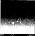
- FIG. 7 is a SEM photograph of a specimen in which a surface of Mg alloy prepared by adding 0.5 wt% SiO 2 to pure magnesium molten metal was polished for EPMA mapping. You can see the grain boundaries faintly in the picture.
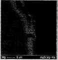
- FIG. 8 is an EPMA (Electron Probe Micro Analyzer) Mapping photograph of an Mg alloy prepared by adding 0.5 wt% SiO 2 to pure magnesium molten metal. It can be seen that magnesium is present over all regions of the specimen.
- EPMA Electro Probe Micro Analyzer
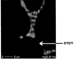
- FIG. 9 is an EPMA Mapping photograph of a silicon element, and it can be seen that a silicon element exists along a grain boundary. The blue area in the picture is the part without the corresponding element. It can be seen from FIG. 7 and FIG. 8 that the Si existing region overlaps with the Mg existing region. This indirectly suggests that Mg and Si constitute a compound. This is because Si separated from SiO 2 forms a phase with Mg (other alloying elements) without being dissolved in Mg base.
- FIG 14 is a graph showing point analysis of EPMA when 0.5 wt% SiO 2 is added to a magnesium alloy (AM60) prepared according to the present invention.
- the point component analysis of the phase-forming compound shows that the magnesium-aluminum-silicon compound was formed by directly adding SiO 2 to the magnesium alloy melt.
- Table 4 below shows the ratio of Mg, Al, and Si counted at each point (1, 2, 3).
- FIG. 15 is a graph illustrating a mapping analysis of a magnesium alloy prepared by adding 0.5 wt% SiO 2 to a commercial magnesium alloy (AM60) according to the present invention. As a photograph of magnesium, it can be seen that magnesium exists in all regions.
- FIG. 16 is a photograph showing a mapping analysis of aluminum (Al) of a magnesium alloy prepared by adding 0.5 wt% SiO 2 to an Mg alloy (AM60) according to the present invention. It can be seen that it is present along the grain boundaries as a photograph of the aluminum element.
- FIG. 17 is a photograph showing mapping analysis of silicon (Si) of a magnesium alloy prepared by adding 0.5 wt% SiO 2 to an Mg alloy (AM60) according to the present invention.
- Si silicon
- AM60 Mg alloy
- blue is the part without the corresponding element.
- Mg, Si, and Al form a compound. This is because Si separated from SiO 2 forms a phase with Mg and other alloying elements Al without being dissolved in the Mg base.
- FIG. 18 is a photograph showing mapping analysis of oxygen (O) of a magnesium alloy prepared by adding 0.5 wt% SiO 2 to an Mg alloy (AM60) according to the present invention. 18, it can be seen that no oxygen component is present in the alloy. This shows that oxygen is separated from SiO 2 added to the Mg alloy and disappears in the form of O 2 gas in the molten state, or is removed in the alloy by dross in the form of MgO (or a compound of Al or other alloying elements).
- O oxygen
- the present invention can solve the problems caused by the direct addition of silicon as a new magnesium-based alloy by adding a silicon compound to the magnesium or magnesium alloy molten metal.
- the silicon produced by the reduction reaction from the added silicon compound is not dissolved in the magnesium alloy, but directly forms a phase of the compound (typically Mg 2 Si). Due to the phase formation of the compound, the structure of the magnesium alloy is refined to improve mechanical properties.
- a phase of the compound typically Mg 2 Si
- the silicon element supplied to the molten metal through the reduction reaction of the silicon compound is combined with the magnesium element of the molten metal or other alloying elements to form a high temperature stable compound.
- the compound thus produced helps to improve the properties of the magnesium alloy.
Landscapes
- Chemical & Material Sciences (AREA)
- Engineering & Computer Science (AREA)
- Mechanical Engineering (AREA)
- Materials Engineering (AREA)
- Metallurgy (AREA)
- Organic Chemistry (AREA)
- Manufacturing & Machinery (AREA)
- Life Sciences & Earth Sciences (AREA)
- General Life Sciences & Earth Sciences (AREA)
- Geology (AREA)
- Environmental & Geological Engineering (AREA)
- Silicon Compounds (AREA)
- Manufacture And Refinement Of Metals (AREA)
Abstract
본 발명은 마그네슘계 합금 및 그 제조 방법에 관한 것으로, 마그네슘 합금을 액상으로 용해하는 단계와, 상기 마그네슘 합금이 용해된 용탕에 실리콘화합물을 첨가하는 단계와, 상기 용탕과 상기 첨가된 실리콘화합물의 충분한 반응을 통해, 상기 실리콘화합물이 마그네슘 합금 속에 실질적으로 잔류되지 않도록 소진시키는 단계, 및 상기 소진 결과 생성된 실리콘을 상기 마그네슘 합금 속에 실질적으로 잔류되지 않도록 소진시키는 단계를 포함한다.
Description
본 발명은 실리콘 대신 실리콘화합물을 마그네슘이나 마그네슘 합금의 용탕에 직접 첨가하여 제조된 마그네슘계 합금 및 그 제조 방법에 관한 것이다. 더욱 상세하게는 마그네슘이나 마그네슘 합금의 용탕에 실리콘화합물을 투입하여 용탕에서 실리콘화합물의 환원반응을 유도하고, 상기 환원반응으로 생성된 실리콘을 상기 용탕 속에서 화합물화시킨 마그네슘 합금 및 이의 제조 방법에 관한 것이다.
일반적으로 마그네슘 또는 마그네슘 합금은 실용 금속 중에서 가장 가벼운 금속으로, 비강도, 비강성이 우수하여 경량 구조 재료로서 기대되고 있다. 일반적으로 마그네슘 합금은 마그네슘이나 마그네슘 합금에 화합물이 아닌 합금원소를 첨가하여 합금화한다.
본 발명의 목적은 실리콘화합물을 마그네슘 또는 마그네슘 합금 용탕에 첨가하여 새로운 방법으로 제조된 마그네슘계 합금 및 그 제조 방법을 제공하는 데 있다.
본 발명의 또 다른 목적은 기존 마그네슘 또는 마그네슘 합금에 첨가되는 실리콘(Si) 대신 상대적으로 저가인 실리콘화합물(SiO2)을 사용함으로 합금의 제조비용을 절감하는데 있다.
본 발명의 또 다른 목적은 실리콘을 직접 첨가하는 대신, 실리콘화합물을 간접 투입하여 실리콘의 고용을 최소화시켜 첨가 합금원소의 효과를 극대화하는데 있다.
본 발명의 또 다른 목적은 마그네슘 또는 마그네슘 합금 속에 생성되는 실리콘화합물의 양을 보다 극대화시켜 마그네슘 합금의 물성을 증대시키는데 있다.
본 발명이 이루고자 하는 기술적 과제들은 이상에서 언급한 기술적 과제들로 제한되지 않으며, 언급되지 않은 다른 기술적 과제들은 아래의 기재로부터 본 발명이 속하는 기술분야에서 통상의 지식을 가진 자에게 명확하게 이해될 수 있을 것이다.
상기 목적을 달성하기 위한 본 발명의 마그네슘계 합금 제조방법은 마그네슘 또는 마그네슘 합금을 액상으로 용해하는 단계, 상기 마그네슘 또는 마그네슘 합금이 용해된 용탕에 실리콘화합물을 첨가하는 단계, 상기 용탕과 상기 첨가된 실리콘화합물의 반응을 통해, 상기 실리콘화합물을 상기 마그네슘 또는 마그네슘 합금 속에서 적어도 일부를 소진시키는 단계 및, 상기 소진 결과 생성된 실리콘을 상기 마그네슘 또는 마그네슘 합금 속에서 적어도 일부를 반응시키는 단계를 포함한다.
본 발명의 마그네슘계 합금 제조방법은, 마그네슘 또는 마그네슘 합금을 액상으로 용해하는 단계, 상기 마그네슘 또는 마그네슘 합금이 용해된 용탕에 실리콘화합물을 첨가하는 단계, 상기 용탕과 상기 첨가된 실리콘화합물의 충분한 반응을 통해, 상기 실리콘화합물이 마그네슘 합금 속에 실질적으로 잔류되지 않도록 소진시키는 단계 및, 상기 소진 결과 생성된 실리콘을 상기 마그네슘 또는 마그네슘 합금 속에 실질적으로 잔류되지 않도록 반응시키는 단계를 포함한다.
또한, 상기 첨가된 실리콘화합물이 상기 용탕 내부로 혼입되지 않도록 상기 용탕의 표면에 고루 펴주는 단계를 더 포함하기도 한다.
상기 실리콘화합물의 산소원소는 산소 가스의 형태로 제거되거나 또는 용탕속의 마그네슘 원소 및/또는 상기 마그네슘의 합금화 원소와의 결합을 통해서 드로스 형태로 제거되는 것을 특징으로 한다.
또한, 상기 용탕과 상기 첨가된 실리콘화합물의 상기 반응을 상기 용탕의 교반을 통해서 촉진시키는 것을 특징으로 한다.
상기 소진 결과 생성된 실리콘은 상기 마그네슘 합금 속의 마그네슘, 그리고 그 외 합금원소 중 적어도 어느 하나와 화합물을 형성하여 실질적으로 잔류되지 않는 것을 특징으로 한다.
상기 실리콘화합물은 상기 마그네슘 또는 마그네슘 합금과의 반응을 촉진시키기 위해 분말상태인 것을 특징으로 한다.
상기 실리콘화합물은 상기 마그네슘 또는 마그네슘 합금의 용탕과 충분히 반응하여 모두 소진되어 용탕에 상기 실리콘화합물로 잔류하지 않을 수 있는 양까지 투입하는 것을 특징으로 한다.
상기 교반은, 상기 용탕을 전자기적인 교반을 통해서 이루어지거나 상기 용탕을 기계적으로 교반하여 이루어진다.
또한, 상기 교반은, 상기 용탕 표면이 대기중에 노출된 상태에서 행해지는 것이 특징이며, 상기 화합물은 Mg2Si이다.
상기 실리콘화합물은 입자의 크기가 0.1 내지 200㎛이며, 상기 실리콘화합물의 첨가량은 0.001중량%에서 30중량%인 것을 특징으로 한다.
본 발명의 마그네슘계 합금 제조방법은 마그네슘 또는 마그네슘 합금을 액상으로 용해하는 단계, 상기 마그네슘 또는 마그네슘 합금이 용해된 용탕에 실리콘화합물을 첨가하는 단계, 상기 용탕과 상기 첨가된 실리콘화합물의 환원반응을 통해, 상기 실리콘화합물의 산소원소를 제거하는 단계 및, 상기 환원반응으로 생성된 실리콘을 상기 용탕 속에 화합물화시키는 단계를 포함한다.
상기 목적을 달성하기 위한 본 발명의 마그네슘계 합금은 상기와 같은 제조 방법을 통해 형성된다.
이상에서 설명한 바와 같이 본 발명은 실리콘화합물을 마그네슘 또는 마그네슘 합금 용탕에 첨가하여 새로운 마그네슘계 합금을 제조함에 따라 기존의 실리콘의 직접 첨가로 인한 문제점들을 해소할 수 있다.
본 발명은 마그네슘계 합금의 제조 공정 중, 첨가되는 실리콘화합물을 실리콘과 비교하여 저가로 구입하여 사용할 수 있음으로써, 마그네슘 합금의 생산 원가가 절감된다.
또한, 첨가되는 실리콘화합물로부터 환원반응으로 생성된 실리콘은 마그네슘 합금 속에 고용되지 않고, 화합물(대표적으로 Mg2Si)의 상을 직접 형성시킨다. 결과적으로 실리콘화합물의 실리콘의 양을 통해 마그네슘 합금 속에 상형성으로 포함될 실리콘의 함량을 예측할 수 있다. 또한 화합물의 상형성으로 인한 마그네슘 합금의 조직이 미세화되어 기계적 특성이 향상된다.
또 다른 효과로는 실리콘화합물의 환원반응을 통해 용탕에 공급되는 실리콘원소는 용탕의 마그네슘원소나 기타 다른 합금원소들과 결합하여 고온안정한 화합물을 만든다. 이렇게 생성된 화합물은 마그네슘합금의 물성 향상에 도움을 준다.
도 1은 본 발명에 따른 마그네슘 합금의 제조 방법을 도시한 순서도이다.
도 2는 본 발명에서 마그네슘 용탕에 첨가된 실리콘산화물의 해리 순서도이다.
도 3은 본 발명에 따라 Mg에 0.5wt% SiO2 첨가하여 제조한 마그네슘 합금의 조직사진(×50)이다.
도 4는 본 발명에 따라 Mg에 0.5wt% SiO2 첨가하여 제조한 마그네슘 합금의 조직사진(×100)이다.
도 5는 본 발명에 따라 Mg에 0.5wt% SiO2 첨가하여 제조한 마그네슘 합금의 조직사진(×200)이다.
도 6은 본 발명에 따라 Mg에 0.5wt% SiO2 첨가하여 제조한 마그네슘 합금의 EPMA의 점(point) 분석을 나타낸 그래프이다.
도 7은 본 발명에 따라 Mg에 0.5wt% SiO2 첨가하여 제조한 마그네슘 합금의 연마 표면의 SEM 이미지 사진이다.
도 8은 본 발명에 따라 Mg에 0.5wt% SiO2 첨가하여 제조한 마그네슘 합금의 마그네슘(Mg)에 대한 Mapping 분석을 나타낸 사진이다.
도 9는 본 발명에 따라 Mg에 0.5wt% SiO2 첨가하여 제조한 마그네슘 합금의 실리콘(Si)에 대한 Mapping 분석을 나타낸 사진이다.
도 10은 본 발명에 따라 Mg에 0.5wt% SiO2 첨가하여 제조한 마그네슘 합금의 산소(O)에 대한 Mapping 분석을 나타낸 사진이다.
도 11은 본 발명에 따라 Mg합금(AM60)에 0.5wt% SiO2 첨가하여 제조한 마그네슘 합금의 조직사진(×50)이다.
도 12는 본 발명에 따라 Mg합금(AM60)에 0.5wt% SiO2 첨가하여 제조한 마그네슘 합금의 조직사진(×100)이다.
도 13은 본 발명에 따라 Mg합금(AM60)에 0.5wt% SiO2 첨가하여 제조한 마그네슘 합금의 조직사진(×200)이다.
도 14는 본 발명에 따라 Mg합금(AM60)에 0.5wt% SiO2 첨가하여 제조한 마그네슘 합금의 EPMA의 점(point) 분석을 나타낸 그래프이다.
도 15는 본 발명에 따라 Mg합금(AM60)에 0.5wt% SiO2 첨가하여 제조한 마그네슘 합금의 마그네슘(Mg)에 대한 Mapping 분석을 나타낸 사진이다.
도 16은 본 발명에 따라 Mg합금(AM60)에 0.5wt% SiO2 첨가하여 제조한 마그네슘 합금의 알루미늄(Al)에 대한 Mapping 분석을 나타낸 사진이다.
도 17은 본 발명에 따라 Mg합금(AM60)에 0.5wt% SiO2 첨가하여 제조한 마그네슘 합금의 실리콘(Si)에 대한 Mapping 분석을 나타낸 사진이다.
도 18은 본 발명에 따라 Mg합금(AM60)에 0.5wt% SiO2 첨가하여 제조한 마그네슘 합금의 산소(O)에 대한 Mapping 분석을 나타낸 사진이다.
이하, 첨부된 도면을 참조하여 본 발명의 바람직한 실시예를 상세하게 설명한다. 도면들 중 동일한 구성요소들은 가능한 어느 곳에서든지 동일한 부호로 표시한다. 또한 본 발명의 요지를 불필요하게 흐릴 수 있는 공지 기능 및 구성에 대한 상세한 설명은 생략한다.
본 발명에서는 실리콘화합물을 마그네슘 또는 마그네슘 합금의 용탕에 첨가하여 새로운 합금을 제조하는 방법 및 그 합금에 관한 것이다.
도 1은 본 발명에 따른 마그네슘계 합금의 제조 방법을 도시한 순서도이다.
도 1에 도시된 바와 같이 본 발명에 따른 마그네슘계 합금의 제조 방법은 마그네슘 또는 마그네슘 합금의 용탕 형성 단계(S1)와, 실리콘화합물 첨가 단계(S2), 교반 단계(S3), 실리콘화합물 소진 단계(S4), 용탕과 실리콘의 반응 단계(S5), 주조 단계(S6), 및 응고 단계(S7)를 포함한다. 상기 실리콘화합물의 소진 단계(S4)와 상기 용탕과 생성된 실리콘의 반응 단계(S5)는 설명의 편의상 별개의 단계로 분리하였지만, 두 공정(S4, S5)은 거의 동시에 일어난다. 그리고 S4와 S5는 실질적으로 S3의 교반 단계 이전이라도 일어날 수 있다. S4와 S5는 실리콘화합물의 첨가와 동시에 일어날 수 있다.
상기 마그네슘계 용탕 형성 단계(S1)에서는 마그네슘 또는 마그네슘 합금을 도가니에 넣고 보호 가스 분위기에서 400 내지 800℃의 온도를 제공한다. 그러면, 상기 도가니 내의 마그네슘 합금은 용해되어 마그네슘계 용탕을 형성한다.
마그네슘이나 마그네슘 합금의 용해온도
본 발명에서 마그네슘이나 마그네슘합금의 용해를 위한 온도는 순수 마그네슘 금속이 녹는 온도와 마그네슘합금이 녹는 온도를 의미한다. 합금의 종류에 따라 녹는 온도는 차이가 있을 수 있다. 충분한 반응을 위하여는 마그네슘이나 마그네슘합금이 완전히 용해된 상태에서 실리콘화합물이 투입된다. 마그네슘이나 마그네슘합금의 용해 온도는 고상이 충분히 녹아서 완전한 액상으로 존재하는 온도이면 충분하다. 단, 본 발명에서 실리콘화합물의 첨가로 인하여 용탕의 온도가 떨어지는 점을 고려하여 충분히 여유를 갖는 온도범위에서 용탕을 유지하는 작업이 필요하다. 또는 실리콘화합물의 투입시 일정 온도로 가열하여 용탕 속에 투입할 수도 있다.
여기서, 온도가 400℃ 미만이면 마그네슘 합금 용탕이 형성되기 어렵고, 온도가 800℃를 초과하면 마그네슘계 용탕이 발화할 위험이 있다. 일반적으로 금속학에서 합금화가 됨에 따라 용융점은 떨어지는 경우가 많다.
용해온도를 너무 높이 올릴 경우에는 액체금속의 기화가 발생하고 또한 마그네슘의 특성상 쉽게 발화하여 용탕양의 손실을 가져올 수 있고 최종물성에도 악영향을 미칠 수 있다.
마그네슘계 용탕 형성 단계에서 이용된 마그네슘은 순수 마그네슘, 마그네슘 합금 및 그 등가물 중에서 선택된 어느 하나일 수 있다. 또한, 마그네슘 합금은 AZ91D, AM20, AM30, AM50, AM60, AZ31, AS41, AS31, AS21X, AE42, AE44, AX51, AX52, AJ50X, AJ52X, AJ62X, MRI153, MRI230, AM-HP2, 마그네슘-Al, 마그네슘-Al-Re, 마그네슘-Al-Sn, 마그네슘-Zn-Sn, 마그네슘-Si, 마그네슘-Zn-Y 및 그 등가물 중에서 선택된 어느 하나일 수 있다. 본 발명에서는 산업계에서 사용되고 있는 어떠한 마그네슘합금도 사용이 가능하다.
상기 실리콘화합물 첨가 단계(S2)에서는 상기 마그네슘 용탕에 분말 형태의 실리콘화합물을 첨가한다. 여기서, 실리콘화합물은 마그네슘 합금과의 반응을 촉진시키기 위해 분말상태인 것이 바람직하다.
실리콘화합물의 분말 상태
반응을 위하여 투입되는 실리콘화합물은 어떠한 형태로 투입되어도 상관이 없다. 바람직하게는 효율적인 반응을 위하여 반응 표면적을 증대시키기 위하여 분말상태의 투입이 바람직하다. 그러나 0.1㎛미만으로 너무 미세한 경우는 기화되는 마그네슘이나 열풍에 의하여 비산되어 노에 투입되기가 어려움이 발생된다. 그리고 서로 응집되어서 액상의 용융금속과 쉽게 섞이지 않고 덩어리지게 된다. 너무 굵은 경우에는 표면적을 증대시킨다는 관점에서 바람직하지 않다. 이상적인 파우더의 입도는 500㎛ 이하으로 하는 것이 바람직하다. 더욱 바람직하게는 200㎛이하인 것이 좋다.
분말상들의 비산을 방지하기 위하여 분말형태를 응집시킨 팰랫형태의 실리콘화합물을 투입하는 것도 가능하다.
투입되는 실리콘화합물
용탕에 첨가되는 실리콘화합물로는 대표적으로 SiO2가 사용될 수 있다. 그러나 SiO2으로 제한되지 않고 어떠한 종류의 실리콘화합물도 사용될 수 있다.
상기 실리콘화합물 첨가 단계에서 이용된 실리콘화합물의 양은 마그네슘이나 마그네슘 용탕의 양에 의존한다. 용탕 속에 반응으로 첨가될 수 있는 실리콘화합물의 양은 실리콘화합물이 모두 소진되어 최종 마그네슘합금에 실리콘화합물로 잔류하지 않을 수 있는 양까지 투입이 가능하다. 또는 상기 실리콘화합물은 상기 마그네슘 또는 마그네슘 합금의 용탕 속에 잔류하지 않는 정도의 양까지 투입 가능하다. 만일 초과하는 양의 실리콘화합물이 투입되는 경우에는 용탕의 드로스와 함께 제거되거나, 출탕 후 제거된다. 실험을 통하여 용탕의 30중량%까지 투입하는 경우 실리콘화합물이 용탕에서 용이하게 환원반응이 일어나는 것을 확인하였다. 중량%로 0.001 미만의 실리콘화합물의 첨가는 합금화의 효과를 얻기에 미약하였다.
실리콘화합물의 투입양은 목적으로 하는 최종타겟 합금조성에 따라서 결정된다. 즉 마그네슘합금 속에 실리콘을 합금화하길 희망하는 양에 따라서 역계산하여 실리콘화합물의 양을 결정할 수 있다.
상기 교반 단계(S3)에서는 상기 마그네슘 또는 마그네슘 합금 용탕에 첨가되는 실리콘화합물의 0.1wt% 당 1초~60분 동안 교반한다.
여기서 교반 시간이 0.1wt% 당 1초 미만이면 마그네슘 용탕에 화합물이 충분히 반응하지 않고, 교반 시간이 0.1wt% 당 60분을 초과하면 마그네슘 용탕의 교반 시간이 불필요하게 길어질 수 있다. 일반적으로 교반의 시간은 용탕의 크기와 투입되는 실리콘화합물의 양에 의존하다.
화합물 분말의 투입은 필요 양을 일시에 투입하는 방법도 사용할 수 있으나, 반응을 촉진시키고 분말의 응집 가능성을 낮추는 측면에서는 일차 투입 후에 시간차를 가지고 재차 또는 적정량으로 나누어 순차적으로 투입하는 것도 바람직하다. 이를 통해서 표면에서 반응이 주로 일어날 수 있도록 유도할 수 있다.
교반 방법 및 조건
본 발명의 마그네슘 또는 마그네슘합금과 실리콘화합물과의 효율적인 환원반응을 위하여 교반이 바람직하다. 교반의 형태는 용탕을 담고 있는 노주위에 전자기장을 인가할 수 있는 장치를 구비함으로 전자기장 필드를 발생시켜 용탕의 대류(컨벡션)을 유도할 수 있다. 또한 외부에서 용탕에 인위적인 교반(기계적인 교반)을 할 수 있다. 기계적인 교반의 경우 투입되는 실리콘화합물 분말이 뭉치지 않도록 적절하게 교반할 수도 있다. 교반의 궁극적인 목적은 용탕과 투입되는 분말과의 반응을 적절하게 유도하는데 있다.
교반을 위한 시간은 용탕의 온도와 투입되는 실리콘화합물 분말의 상태(예열상태 등)등에 따라 차이가 있을 수 있다. 바람직하게는 용탕표면에서 실리콘화합물 분말이 보이지 않을 때까지 교반하여 주는 것을 원칙으로 한다. 용탕과 실리콘화합물이 충분한 반응을 일으킬 때까지 교반을 하는 것이 바람직하다. 여기서 충분한 반응이라고 함은 실리콘화합물이 용탕과 실질적으로 모두 환원반응하여 소진된 상태를 의미한다.
실리콘화합물(SiO2의 경우)의 비중은 마그네슘이나 마그네슘 합금의 비중보다 크다. 따라서 실리콘화합물이 마그네슘이나 마그네슘 합금의 용탕 속으로 가라앉는다. 그러나 실리콘화합물이 분말인 경우에는 용탕의 점성이 분말의 비중의 영향력보다 크기에 용탕 아래로 하강하지 않고 용탕의 표층부에 부유할 가능성이 더 높다. 결과적으로 본 발명에서는 분말형태의 화합물을 사용하기에 화합물의 교반은 상층부에서 이루어진다고 말할 수 있다. 비중차에 의하여 침강하여 잔류하는 화합물의 경우 합금제조 출탕시 조절하여 제거할 수 있다.
충분한 교반시간 이후에도 유지시간을 갖으면서 미쳐 반응하지 않은 분말이 반응할 수 있는 시간을 부여하는 것이 바람직하다.
교반의 시기
교반의 시기는 화합물 분말의 투입과 동시에 하는 것이 유효하다. 용탕으로 투입된 화합물의 분말이 감지되지 않을 때까지 교반을 계속하여 준다. 투입된 화합물이 환원반응으로 모두 소진된 후 교반을 완료한다.
표면 반응
일반적으로 금속의 합금화의 경우에는 순수한 실리콘의 용해를 돕기 위해서 단순히 용탕을 저어주는 것으로 충분하다. 용탕과 합금원소를 대류(convection)나 교반(stirring)을 시켜서 적극적인 반응을 유도하여 용탕내부에서 반응이 일어나도록 할 수도 있다.
본 발명에서도 이러한 대류나 교반의 방법을 적용한다. 그리고 이외에도 투입되는 실리콘화합물이 용탕의 표면에 투입되면서 교반을 통해서 반응을 촉진시킬 수도 있다. 즉, 용탕 속의 반응뿐만 아니라 용탕 표면에서의 반응을 유도하여 실리콘화합물의 환원반응을 극대화할 수 있다.
본 발명에서는 화합물이 용탕 속에서 반응하기보다는 용탕의 표면에서 반응하도록 반응환경을 조성하는 것이 중요하다. 그러기 위해서는 용탕 표면에 부유하는 화합물을 강제적으로 용탕 안으로 저어주지 않도록 하는 것이 중요하다. 즉, 투입된 실리콘화합물이 용탕 상층부로 부유하지 않고 용탕 내부로 혼입되면 실리콘화합물에서 산소가 분리되는 환원반응이 용이하게 일어나지 않게 된다. 단순히 표면에 펴져 있는 화합물을 용탕의 표면에서 고루 퍼지도록 펼쳐주는 것이 중요하다.
교반을 안하는 것보다는 하는 것이 반응이 잘 일어나고, 용탕의 내부보다는 외부표면(상층부 표면)에서 교반을 하는 것이 더 잘 일어났다. 즉 외부표면(상층부 표면)은 대기와 노출된 분말과 더 반응을 잘 일으켰다. 실리콘화합물의 경우 용탕이 대기중에 접촉하고 있는 것이 환원반응을 위해서는 더 좋았다. 충분한 반응을 위해서는 상층부 교반을 행하여 표면반응을 유도하는 것이 필요하다. 이를 위해서 실리콘화합물의 침강의 가능성을 막기 위하여 용탕에 화합물을 투입하는 즉시 표면교반을 일으키는 것이 중요하다. 또한 실리콘화합물을 동시에 과도한 양을 투입하는 것보다는 용탕의 표면적을 고려하여 적정량을 순차적으로 투입하여 용탕표면에서 실리콘화합물이 반응의 기회를 많이 가질 수 있도록 하는 것이 중요하다.
실리콘화합물의 산소성분은 상기 용탕 상부층의 교반을 통해서 실질적으로 용탕 표면 위로 제거된다. 상기 교반은 상기 용탕 표면으로부터 용탕 전체 깊이의 20% 내외의 상층부에서 교반이 이루어지는 것이 좋다. 20% 이상의 깊이에서는 본 발명에서 바람직한 예시로 제시한 표면반응이 일어나기가 어렵다. 더욱 바람직하게는 상기 용탕 표면으로부터 용탕 전체 깊이의 10% 내외의 상층부에서 교반이 이루어지는 것이 좋다. 이는 실질적으로 부유하는 실리콘화합물을 실제로 용탕깊이에 10% 상위층에서 위치하도록 유도함으로 용탕의 교란을 최소화할 수 있었다.
상기 실리콘화합물의 소진 단계(S4)에서는 상기 용탕과 상기 첨가된 실리콘화합물의 반응을 통해, 실리콘화합물이 마그네슘 합금 속에 적어도 일부 또는 실질적(substantially)으로 잔류되지 않도록 소진시키게 된다. 본 발명에서 투입되는 실리콘화합물은 환원반응에 의하여 전부 소진되는 것이 바람직하다. 그러나, 일부 반응하지 않고 합금내에 남아 있는 경우라도 물성에 크게 영향을 미치지 않는 경우에도 유효하다.
여기에서, 실리콘화합물을 소진시킨다는 것은, 실리콘화합물에서 산소 성분을 제거하는 것이다. 상기 산소 성분은 산소(O2) 가스의 형태로 제거되거나, 또는 용탕속의 마그네슘 또는 그 합금성분과의 결합을 통해서 드로스(dross)나 슬러지형태로 제거될 수 있다.
상기 실리콘 반응 단계(S5)에서는, 상기 실리콘화합물의 소진 결과로 생성된 실리콘을 마그네슘 합금 속에 적어도 일부 또는 실질적으로 잔류되지 않도록 반응시키게 된다. 여기서, 소진 결과 생성된 실리콘은 상기 마그네슘 합금 속의 마그네슘, 그리고 상기 용탕속의 그 외 합금원소(성분) 중 적어도 어느 하나와 화합물화되어 실질적으로 잔류되지 않도록 한다. 여기서 실리콘화합물은 실리콘의 공급원으로 작용한다.
결국, 첨가된 실리콘화합물은 용탕인 마그네슘 합금과의 반응을 통해 산소성분이 제거되어 적어도 일부 또는 실질적으로 없어지며, 산소 성분이 제거된 실리콘은 마그네슘 합금 속의 마그네슘, 그리고 상기 용탕속의 그 외 합금원소 중 적어도 어느 하나와 화합물화되어 마그네슘 합금 속에 적어도 일부 또는 실질적으로 잔류되지 않게 된다. 지금까지 설명한 과정은 도 1과 도 2에 도시되어 있다. 도 2는 본 발명에서 마그네슘 용탕에 첨가하여 사용되는 실리콘화합물의 해리 순서도이다.
한편, 주조 단계(S6)에서는 상기 마그네슘 용탕을 상온이나 예열상태의 주형에 넣어 주조한다. 여기서, 상기 주형은 금형, 세라믹형, 그라파이트형 및 그 등가물 중에서 선택된 어느 하나를 이용할 수 있다. 또한, 주조 방식은 중력 주조, 연속 주조 및 그 등가 방식이 가능하다.
상기 응고 단계(S7)에서는 상기 주형을 상온으로 냉각시킨 후 주형에서 마그네슘 합금 잉곳을 꺼낸다. 상기와 같은 방법으로 제조된 마그네슘 합금은 아래에서 설명하겠지만 마그네슘계 합금 속에 마그네슘, 알루미늄, 그리고 상기 용탕속의 그 외 합금원소 중 적어도 어느 하나를 포함하는 형태를 갖게 된다.
순수한 마그네슘 용탕의 경우에는 용탕속의 마그네슘성분은 실리콘과 반응하여 마그네슘(실리콘)화합물을 형성한다. 일예로 실리콘화합물이 SiO2인 경우는 Mg2Si가 형성된다. 그리고 SiO2를 구성하고 있던 산소는 O2가 되어 용탕 밖으로 배출되거나, Mg와 결합하여 MgO가 되고 드로스 형태로 배출된다.(아래 반응식 1을 참조)
반응식 1
Pure Mg + SiO2 -> Mg (Matrix) + Mg2Si
... [O2 발생 + MgO dross발생]
마그네슘 합금 용탕의 경우에는 용탕속의 마그네슘성분은 실리콘과 반응하여 마그네슘(실리콘) 화합물을 형성한다. 또한 마그네슘, 알루미늄과 함께 합금원소가 실리콘과 화합물을 형성한다. 일예로 실리콘화합물이 SiO2인 경우는 Mg2Si 또는 (Mg, Al, 기타 합금원소)Si가 형성된다. 그리고 SiO2를 구성하고 있던 산소는 순수 마그네슘의 경우와 같이 O2가 되어 용탕 밖으로 배출되거나, Mg와 결합하여 MgO가 되고 드로스 형태로 배출된다.(아래 반응식 2를 참조)
반응식 2
Mg Alloy + SiO2 -> Mg Alloy (Matrix) +
(Mg2Si + (Mg, Al, 기타 합금원소)Si)
... [O2 발생 + MgO dross발생]
이상에서 설명한 바와 같이 본 발명은 종래의 마그네슘 합금의 생산방법과 비교하여 보다 경제적으로 마그네슘 합금을 제조공법이다. 실리콘화합물을 실리콘을 대신하여 마그네슘이나 마그네슘합금에 첨가함으로 상대적으로 합금화하기가 용이하다. 실리콘을 직접 첨가하지 않고, 화학적으로 안정한 실리콘화합물을 첨가함으로써 궁극적으로 합금의 물성에 중요한 Mg2Si 또는 Mg/Al과 Si의 화합물의 상을 직접 만들 수 있다. 이로 인하여 마그네슘합금의 조직이 미세화되며 강도가 향상된다.
또한, 실리콘을 마그네슘이나 마그네슘합금에 직접 투입하는 경우 마그네슘 합금에서 실리콘의 고용화가 일정한 양 발생하는 반면에, 본 발명의 경우에는 실리콘화합물을 첨가시 실리콘의 고용되는 정도가 실리콘을 직접 첨가하는 경우와 비교하여 없거나 극히 적다. 따라서 실리콘화합물을 첨가하여 마그네슘합금을 제조하는 경우에는 실리콘이 직접 마그네슘 및 기타 합금원소들과 화합물을 형성함으로 인해 물성이 실리콘을 직접 첨가하였을 때 보다 향상됨을 볼 수 있다.
본 발명에서 제조된 상기 마그네슘계 합금은 캐스팅 합금(casting alloy), 러트 합금(wrought alloy), 크립 합금(creep alloy), 댐핑 합금(damping alloy), 분해 가능한 바이오 합금(degradable bio alloy) 및 파우더 메탈러지(powder metallurgy)중에서 선택된 적어도 어느 하나로 이용될 수 있다.
본 발명의 제조 방법으로 제조된 마그네슘계 합금은 경도(HRF)가 40 내지 80일 수 있다. 그러나 이러한 경도값은 가공 방법 및 열처리 등에 따라 다양하게 변화하기 때문에, 이러한 경도 값으로 본 발명에 따른 마그네슘계 합금을 한정하는 것은 아니다.
다음의 표 1은 본 발명에서 제조된 마그네슘 합금의 상온에서의 경도를 나타낸 표이다. 순수 마그네슘에 실리콘산화물을 중량비로 0.5wt% SiO2 첨가하여 제조된 마그네슘 합금의 경도를 측정하였다.
표 1
| 시편번호 | 1 | 2 | 3 | 4 | 5 | 6 | 7 | 평균 |
| 경도(HR15T) | 39 | 41 | 36 | 42 | 42 | 36 | 39 | 39.3 |
다음의 표 2는 본 발명에서 제조된 마그네슘 합금의 상온에서의 경도를 나타낸 표이다. 마그네슘 합금인 AM60에 실리콘산화물을 중량비로 0.5wt% SiO2 첨가하여 제조된 마그네슘 합금의 경도를 측정하였다.
표 2
| 시편번호 | 1 | 2 | 3 | 4 | 5 | 6 | 7 | 평균 |
| 경도(HRF) | 43 | 44 | 46 | 42 | 43 | 41 | 44 | 43.3 |
본 발명에서 생산된 마그네슘합금의 경우 동종의 마그네슘 합금의 경도보다 높게 나타났다. 그 이유는 환원반응으로 생성된 실리콘이 마그네슘이나 마그네슘 합금 속의 Mg 및/또는 기타 합금원소들과 화합물을 형성시키기 때문이다. 특히, 생성되는 Mg2Si는 높은 경도와 낮은 열팽찰계수를 가지고, 높은 융점(1085℃)을 갖기 때문에 마그네슘 합금의 기계적인 물성을 향상시킨다.
도 3, 4, 5는 본 발명에 따라 Mg에 0.5wt% SiO2를 첨가하여 제조된 마그네슘 합금의 조직사진(각각 ×50, ×100, ×200)이다.
도 11, 12, 13은 본 발명에 따라 상용 마그네슘(AM60)에 0.5wt% SiO2을 첨가하여 제조된 마그네슘 합금의 조직사진(각각 ×50, ×100, ×200)이다. 상기 조직사진들에서 볼 수 있듯이 마그네슘 또는 마그네슘합금의 용탕에 SiO2를 첨가하여 조직이 미세화되는 것을 확인하였다. 이는 환원반응으로 생성된 실리콘과, 마그네슘 및 그 밖의 합금원소들과 상형성으로 인해 생성된 화합물이 미세조직의 결정립 성장을 억제하였기 때문이다. 본 발명에서 SiO2가 첨가되어 제조된 마그네슘합금의 경우, 순수 Mg합금과 비교하여 결정립의 크기가 현저히 줄어들어 조직이 미세화됨을 확인할 수 있었다.
도 6은 본 발명에 따라 Mg에 0.5wt% SiO2를 첨가하여 제조된 마그네슘 합금 EPMA의 점(point) 분석을 나타낸 그래프이다. 상형성된 화합물의 포인트 성분 분석결과를 통해 마그네슘 용탕에 실리콘산화물(SiO2)을 직접 첨가하여 마그네슘-실리콘계 화합물을 형성시킨 것을 확인할 수 있다.
표 3
| Mg | Si | Total | |
| Point 1 | 90.96 | 9.04 | 100 |
| Point 2 | 81.16 | 18.84 | 100 |
| Point 3 | 84.44 | 15.56 | 100 |
도 7은 순수 마그네슘 용탕에 0.5wt%의 SiO2를 첨가하여 제조한 Mg합금을 EPMA Mapping을 위해서 표면을 연마한 시편의 SEM사진이다. 사진에서 희미하게 결정입계를 확인할 수 있다.
도 8은 순수 마그네슘 용탕에 0.5wt%의 SiO2를 첨가하여 제조한 Mg합금을 분석한 EPMA (Electron Probe Micro Analyzer) Mapping 사진이다. 마그네슘 성분원소가 시편의 모든 영역에 걸쳐 존재함을 알 수 있다.
도 9는 실리콘 원소에 대한 EPMA Mapping 사진으로서 결정립계를 따라 실리콘 성분원소가 존재함을 알 수 있다. 사진에서 청색 영역은 해당 성분원소가 없는 부분이다. 도 7과 도 8을 통해 Si의 존재영역이 Mg 존재영역과 겹침을 확인할 수 있다. 이는 Mg와 Si가 화합물을 이루고 있음을 간접적으로 시사한다. SiO2에서 분리된 Si가 Mg기지에 고용되지 않고 Mg(기타 합금원소들)과 상을 형성하였기 때문이다.
도 10을 보면 합금 내에 산소 성분이 존재하지 않는 것을 알 수 있다. 이는 Mg합금에 첨가된 SiO2에서 산소가 분리되어 용탕상태에서 O2 가스형태로 없어지거나 아니면 MgO(또는 Al이나 기타 합금원소의 화합물)형태의 드로스로 합금 내에서 제거되는 것을 보여 준다.
도 14는 본 발명에 따라 제조된 마그네슘 합금(AM60)에 0.5wt% SiO2를 첨가한 경우의 EPMA의 점(point) 분석을 나타낸 그래프이다. 상형성된 화합물의 포인트 성분 분석결과를 보면 마그네슘합금 용탕에 SiO2를 직접 첨가하여 마그네슘-알루미늄-실리콘계 화합물이 형성된 것을 알 수 있다.
아래 표 4는 각 포인트(1, 2, 3)에서 카운트된 Mg, Al과 Si의 비율을 나타낸다.
표 4
| Mg | Al | Si | Total | |
| Point 1 | 78.96 | 3.59 | 17.45 | 100 |
| Point 2 | 70.11 | 3.18 | 26.71 | 100 |
| Point 3 | 77.62 | 3.15 | 19.23 | 100 |
도 15는 본 발명에 따라 상용 마그네슘 합금(AM60)에 0.5wt% SiO2를 첨가하여 제조된 마그네슘 합금의 Mapping 분석을 나타낸 그래프이다. 마그네슘에 대한 사진으로서 모든 영역에 걸쳐 마그네슘이 존재함을 알 수 있다.
도 16은 본 발명에 따라 Mg합금(AM60)에 0.5wt% SiO2 첨가하여 제조된 마그네슘 합금의 알루미늄(Al)에 대한 Mapping 분석을 나타낸 사진이다. 알루미늄 원소에 대한 사진으로서 결정립계를 따라 존재함을 알 수 있다.
도 17은 본 발명에 따라 Mg합금(AM60)에 0.5wt% SiO2 첨가하여 제조된 마그네슘 합금의 실리콘(Si)에 대한 Mapping 분석을 나타낸 사진이다. 사진에서 청색은 해당 성분원소가 없는 부분이다. 도 17의 Si의 존재영역이 도 16의 Al 존재영역과 겹친다는 점을 확인할 수 있다. 이는 Mg와 Si와 Al이 화합물을 이루고 있음을 간접적으로 시사한다. SiO2에서 분리된 Si가 Mg기지에 고용되지 않고 Mg와 기타 합금원소인 Al과 상을 형성하였기 때문이다.
도 18은 본 발명에 따라 Mg합금(AM60)에 0.5wt% SiO2 첨가하여 제조된 마그네슘 합금의 산소(O)에 대한 Mapping 분석을 나타낸 사진이다. 도 18을 보면 합금 내에 산소 성분이 존재하지 않는 것을 알 수 있다. 이는 Mg합금에 첨가된 SiO2에서 산소가 분리되어 용탕 상태에서 O2 가스형태로 없어지거나, MgO(또는 Al이나 기타 합금원소의 화합물)형태의 드로스로 합금 내에서 제거되는 것을 보여 준다.
이상에서 설명한 바와 같이 본 발명은 실리콘화합물을 마그네슘 또는 마그네슘 합금 용탕에 첨가하여 새로운 마그네슘계 합금을 제조함에 따라 기존의 실리콘의 직접 첨가로 인한 문제점들을 해소할 수 있다.
첨가되는 실리콘화합물로부터 환원반응으로 생성된 실리콘은 마그네슘 합금 속에 고용되지 않고, 화합물(대표적으로 Mg2Si)의 상을 직접 형성시킨다. 화합물의 상형성으로 인한 마그네슘 합금의 조직이 미세화되어 기계적 특성이 향상된다.
즉, 실리콘화합물의 환원반응을 통해 용탕에 공급되는 실리콘원소는 용탕의 마그네슘원소나 기타 다른 합금원소들과 결합하여 고온안정한 화합물을 만든다. 이렇게 생성된 화합물은 마그네슘합금의 물성 향상에 도움을 준다.
상기의 본 발명은 바람직한 실시예를 중심으로 살펴보았으며, 본 발명이 속하는 기술분야에서 통상의 지식을 가진 자는 본 발명의 본질적 기술 범위 내에서 상기 본 발명의 상세한 설명과 다른 형태의 실시예들을 구현할 수 있을 것이다. 여기서 본 발명의 본질적 기술범위는 특허청구범위에 나타나 있으며, 그와 동등한 범위 내에 있는 모든 차이점은 본 발명에 포함된 것으로 해석되어야 할 것이다.
Claims (23)
- 마그네슘계 합금을 제조하는 방법에 있어서,마그네슘 또는 마그네슘 합금을 액상으로 용해하는 단계;상기 마그네슘 또는 마그네슘 합금이 용해된 용탕에 실리콘화합물을 첨가하는 단계;상기 용탕과 상기 첨가된 실리콘화합물의 반응을 통해, 상기 실리콘화합물을 상기 마그네슘 또는 마그네슘 합금 속에서 적어도 일부를 소진시키는 단계; 및상기 소진 결과 생성된 실리콘을 상기 마그네슘 또는 마그네슘 합금 속에서 적어도 일부를 반응시키는 단계;를 포함하는, 마그네슘계 합금 제조 방법.
- 마그네슘계 합금을 제조하는 방법에 있어서,마그네슘 또는 마그네슘 합금을 액상으로 용해하는 단계;상기 마그네슘 또는 마그네슘 합금이 용해된 용탕에 실리콘화합물을 첨가하는 단계;상기 용탕과 상기 첨가된 실리콘화합물의 충분한 반응을 통해, 상기 실리콘화합물이 마그네슘 합금 속에 실질적으로 잔류되지 않도록 소진시키는 단계; 및상기 소진 결과 생성된 실리콘을 상기 마그네슘 또는 마그네슘 합금 속에 실질적으로 잔류되지 않도록 반응시키는 단계;를 포함하는, 마그네슘계 합금 제조 방법.
- 제 2 항에 있어서,상기 첨가된 실리콘화합물이 상기 용탕 내부로 혼입되지 않도록 상기 용탕의 표면에 고루 펴주는 단계를 더 포함하는, 마그네슘계 합금 제조 방법.
- 제 2 항에 있어서,상기 실리콘화합물의 산소원소는 산소 가스의 형태로 제거되거나 또는 용탕속의 마그네슘 원소 및/또는 상기 마그네슘의 합금화 원소와의 결합을 통해서 드로스 형태로 제거되는 것을 특징으로 하는, 마그네슘계 합금 제조 방법.
- 제 2 항에 있어서,상기 용탕과 상기 첨가된 실리콘화합물의 상기 반응을 상기 용탕의 교반을 통해서 촉진시키는 것을 특징으로 하는, 마그네슘계 합금 제조 방법.
- 제 2 항에 있어서,상기 소진 결과 생성된 실리콘은 상기 마그네슘 합금 속의 마그네슘, 그리고 그 외 합금원소 중 적어도 어느 하나와 화합물을 형성하여 실질적으로 잔류되지 않는, 마그네슘계 합금 제조 방법.
- 제 2 항에 있어서,상기 실리콘화합물은 상기 마그네슘 또는 마그네슘 합금과의 반응을 촉진시키기 위해 분말상태인 것을 특징으로 하는, 마그네슘계 합금 제조 방법.
- 제 2 항에 있어서,상기 실리콘화합물은 상기 마그네슘 또는 마그네슘 합금의 용탕과 충분히 반응하여 모두 소진되어 용탕에 상기 실리콘화합물로 잔류하지 않을 수 있는 양까지 투입하는 것을 특징으로 하는, 마그네슘계 합금 제조 방법.
- 제 5 항에 있어서,상기 교반은, 상기 용탕을 전자기적인 교반을 통해서 이루어지는 것을 특징으로 하는, 마그네슘계 합금 제조 방법.
- 제 5 항에 있어서,상기 교반은, 상기 용탕을 기계적으로 교반하는 것을 특징으로 하는, 마그네슘계 합금 제조 방법.
- 제 5 항에 있어서,상기 교반은, 상기 용탕 표면이 대기중에 노출된 상태에서 행함을 특징으로 하는, 마그네슘계 합금 제조 방법.
- 제 6 항에 있어서, 상기 화합물은 Mg2Si인, 마그네슘계 합금 제조 방법.
- 제 7 항에 있어서,상기 실리콘화합물은 입자의 크기가 0.1 내지 200㎛인 것을 특징으로 하는, 마그네슘계 합금 제조 방법.
- 제 8 항에 있어서,상기 실리콘화합물의 첨가량은 0.001중량%에서 30중량%임을 특징으로 하는, 마그네슘계 합금 제조 방법.
- 마그네슘계 합금을 제조하는 방법에 있어서,마그네슘 또는 마그네슘 합금을 액상으로 용해하는 단계;상기 마그네슘 또는 마그네슘 합금이 용해된 용탕에 실리콘화합물을 첨가하는 단계;상기 용탕과 상기 첨가된 실리콘화합물의 환원반응을 통해, 상기 실리콘화합물의 산소원소를 제거하는 단계; 및상기 환원반응으로 생성된 실리콘을 상기 용탕 속에 화합물화시키는 단계; 를 포함하는, 마그네슘계 합금 제조 방법.
- 제 15 항에 있어서,상기 산소원소는, 산소 가스의 형태로 제거되거나, 또는 용탕속의 마그네슘 및/또는 마그네슘의 합금화 원소와의 결합을 통해서 드로스 형태로 제거되는 것을 특징으로 하는, 마그네슘계 합금 제조 방법.
- 제 15 항에 있어서,상기 환원반응을 통해 생성된 실리콘은 상기 마그네슘 합금 속의 마그네슘과 그리고 그 외 합금원소중 적어도 어느 하나와 화합물화되어 실질적으로 잔류되지 않는, 마그네슘계 합금 제조 방법.
- 제 15 항에 있어서,상기 실리콘화합물은 상기 마그네슘 또는 마그네슘 합금과의 반응을 촉진시키기 위해 분말상태인 것을 특징으로 하는, 마그네슘계 합금 제조 방법.
- 제 15 항에 있어서,상기 실리콘화합물은 상기 마그네슘 또는 마그네슘 합금의 용탕과 충분히 반응하여 모두 소진되어 용탕에 실리콘화합물로 잔류하지 않을 수 있는 양까지 투입하는 것을 특징으로 하는, 마그네슘계 합금 제조 방법.
- 제 17 항에 있어서,상기 환원반응을 통해 생성된 실리콘과 상기 마그네슘의 화합물은 Mg2Si인, 마그네슘계 합금 제조 방법.
- 제 18 항에 있어서,상기 실리콘화합물은 입자의 크기가 0.1 내지 200㎛인 것을 특징으로 하는, 마그네슘계 합금 제조 방법.
- 제 19 항에 있어서,상기 실리콘화합물의 첨가량은 0.001중량%에서 30중량%을 특징으로 하는, 마그네슘계 합금 제조 방법.
- 제 1 항 내지 제 22 항 중적어도 어느 한 항의 제조 방법으로 형성된, 마그네슘계 합금.
Priority Applications (1)
| Application Number | Priority Date | Filing Date | Title |
|---|---|---|---|
| US14/117,574 US9447482B2 (en) | 2011-05-20 | 2012-05-18 | Magnesium-based alloy produced using a silicon compound and method for producing same |
Applications Claiming Priority (2)
| Application Number | Priority Date | Filing Date | Title |
|---|---|---|---|
| KR10-2011-0048099 | 2011-05-20 | ||
| KR1020110048099A KR101335010B1 (ko) | 2011-05-20 | 2011-05-20 | 실리콘화합물을 이용하여 제조된 마그네슘계 합금 및 그 제조 방법 |
Publications (2)
| Publication Number | Publication Date |
|---|---|
| WO2012161484A2 true WO2012161484A2 (ko) | 2012-11-29 |
| WO2012161484A3 WO2012161484A3 (ko) | 2013-01-17 |
Family
ID=47217879
Family Applications (1)
| Application Number | Title | Priority Date | Filing Date |
|---|---|---|---|
| PCT/KR2012/003964 Ceased WO2012161484A2 (ko) | 2011-05-20 | 2012-05-18 | 실리콘화합물을 이용하여 제조된 마그네슘계 합금 및 그 제조 방법 |
Country Status (3)
| Country | Link |
|---|---|
| US (1) | US9447482B2 (ko) |
| KR (1) | KR101335010B1 (ko) |
| WO (1) | WO2012161484A2 (ko) |
Families Citing this family (8)
| Publication number | Priority date | Publication date | Assignee | Title |
|---|---|---|---|---|
| US20170268088A1 (en) | 2014-02-21 | 2017-09-21 | Terves Inc. | High Conductivity Magnesium Alloy |
| US10689740B2 (en) | 2014-04-18 | 2020-06-23 | Terves, LLCq | Galvanically-active in situ formed particles for controlled rate dissolving tools |
| WO2015127174A1 (en) | 2014-02-21 | 2015-08-27 | Terves, Inc. | Fluid activated disintegrating metal system |
| US9757796B2 (en) | 2014-02-21 | 2017-09-12 | Terves, Inc. | Manufacture of controlled rate dissolving materials |
| US10865465B2 (en) | 2017-07-27 | 2020-12-15 | Terves, Llc | Degradable metal matrix composite |
| US11167343B2 (en) | 2014-02-21 | 2021-11-09 | Terves, Llc | Galvanically-active in situ formed particles for controlled rate dissolving tools |
| US10758974B2 (en) | 2014-02-21 | 2020-09-01 | Terves, Llc | Self-actuating device for centralizing an object |
| WO2015161171A1 (en) | 2014-04-18 | 2015-10-22 | Terves Inc. | Galvanically-active in situ formed particles for controlled rate dissolving tools |
Family Cites Families (12)
| Publication number | Priority date | Publication date | Assignee | Title |
|---|---|---|---|---|
| JPH05148564A (ja) * | 1991-11-22 | 1993-06-15 | Suzuki Motor Corp | MgまたはMg合金へのSi添加方法 |
| JPH0841564A (ja) * | 1994-08-01 | 1996-02-13 | Suzuki Motor Corp | Mg基複合材と、その製造方法 |
| JP4736222B2 (ja) | 2001-04-10 | 2011-07-27 | トヨタ自動車株式会社 | マグネシウム合金の製造方法 |
| JP2003183747A (ja) | 2001-12-12 | 2003-07-03 | Toyota Motor Corp | マグネシウム合金の製造方法およびマグネシウム合金の浄化剤 |
| KR100681539B1 (ko) | 2005-02-25 | 2007-02-12 | 한국생산기술연구원 | 산화칼슘이 첨가된 마그네슘 합금 및 그의 제조방법 |
| CA2721761C (en) * | 2009-11-20 | 2016-04-19 | Korea Institute Of Industrial Technology | Aluminum alloy and manufacturing method thereof |
| KR101367892B1 (ko) * | 2010-12-27 | 2014-02-26 | 한국생산기술연구원 | 고온용 마그네슘 합금 및 그 제조 방법 |
| KR101367894B1 (ko) * | 2011-01-06 | 2014-02-26 | 한국생산기술연구원 | 상온용 마그네슘 합금 |
| RU2564370C2 (ru) * | 2010-03-29 | 2015-09-27 | Корейский Институт Промышленных Технологий | Сплав на магниевой основе с повышенной текучестью и устойчивостью к горячим надрывам и способ его получения |
| KR101341091B1 (ko) * | 2011-05-20 | 2014-01-02 | 한국생산기술연구원 | 알루미늄 합금 및 그 제조방법 |
| KR101402897B1 (ko) * | 2011-05-20 | 2014-06-02 | 한국생산기술연구원 | 합금제조방법 및 이에 의해 제조된 합금 |
| KR101340292B1 (ko) * | 2011-05-20 | 2013-12-11 | 한국생산기술연구원 | 알루미늄 합금 및 그 제조방법 |
-
2011
- 2011-05-20 KR KR1020110048099A patent/KR101335010B1/ko active Active
-
2012
- 2012-05-18 WO PCT/KR2012/003964 patent/WO2012161484A2/ko not_active Ceased
- 2012-05-18 US US14/117,574 patent/US9447482B2/en active Active
Also Published As
| Publication number | Publication date |
|---|---|
| WO2012161484A3 (ko) | 2013-01-17 |
| KR101335010B1 (ko) | 2013-12-02 |
| KR20120130025A (ko) | 2012-11-28 |
| US20140202284A1 (en) | 2014-07-24 |
| US9447482B2 (en) | 2016-09-20 |
Similar Documents
| Publication | Publication Date | Title |
|---|---|---|
| WO2011122785A2 (en) | Magnesium-based alloy for high temperature and manufacturing method thereof | |
| WO2011122784A2 (en) | Magnesium alloy for room temperature and manufacturing method thereof | |
| WO2011122786A2 (en) | Magnesium-based alloy with superior fluidity and hot-tearing resistance and manufacturing method thereof | |
| WO2016137211A1 (ko) | 열전도성과 난연성이 우수한 소성가공용 마그네슘 합금과 그의 제조방법 | |
| KR101335010B1 (ko) | 실리콘화합물을 이용하여 제조된 마그네슘계 합금 및 그 제조 방법 | |
| WO2020122472A2 (ko) | 마그네슘 합금재 및 이의 제조방법 | |
| WO2016137210A1 (ko) | 열전도성과 난연성이 우수한 소성가공용 마그네슘 합금과 그의 제조방법 | |
| WO2021230392A1 (ko) | 고엔트로피 합금 및 이의 제조 방법 | |
| WO2012161463A2 (ko) | 합금제조방법 및 이에 의해 제조된 합금 | |
| WO2015126054A1 (ko) | 마그네슘 합금 판재 및 이의 제조방법 | |
| WO2020067704A1 (ko) | 마그네슘 합금 판재 및 이의 제조방법 | |
| CN107447144A (zh) | 一种耐热稀土铝合金及其制备方法 | |
| WO2018117713A1 (ko) | 난연성이 우수한 고강도 마그네슘 합금 및 그 제조방법 | |
| WO2022235053A1 (ko) | 3d 프린팅용 고강도 알루미늄 합금 및 이의 제조방법 | |
| WO2012134243A2 (ko) | Mg합금용 Mg-Al-Ca계 모합금 및 이의 제조하는 방법 | |
| CN1109115C (zh) | 耐热阻燃压铸镁合金及其熔炼铸造工艺 | |
| WO2012161485A2 (ko) | 실리콘화합물과 칼슘화합물을 이용하여 제조된 마그네슘계 합금 및 그 제조 방법 | |
| WO2022220534A1 (en) | Aluminum alloys | |
| WO2014077653A1 (ko) | 아연합금 및 이의 제조방법 | |
| WO2013055074A2 (ko) | 다이캐스팅용 고열전도도 Al-Mg-Fe-Si 합금 | |
| WO2011122776A2 (en) | Melting method of magnesium-based metal and magnesium alloy manufactured using the same | |
| WO2012161459A2 (ko) | 알루미늄 합금 및 그 제조방법 | |
| WO2013157903A1 (ko) | 알루미늄 합금 및 이의 제조 방법 | |
| CN112626392B (zh) | 一种铸造铝硅合金及其制备方法 | |
| WO2018117762A1 (ko) | 내식성이 우수한 마그네슘 합금 판재 및 그 제조방법 |
Legal Events
| Date | Code | Title | Description |
|---|---|---|---|
| 121 | Ep: the epo has been informed by wipo that ep was designated in this application |
Ref document number: 12789614 Country of ref document: EP Kind code of ref document: A2 |
|
| WWE | Wipo information: entry into national phase |
Ref document number: 14117574 Country of ref document: US |
|
| NENP | Non-entry into the national phase |
Ref country code: DE |
|
| 122 | Ep: pct application non-entry in european phase |
Ref document number: 12789614 Country of ref document: EP Kind code of ref document: A2 |