WO2012164609A1 - Détendeur à spirale et dispositif à cycle de réfrigération - Google Patents
Détendeur à spirale et dispositif à cycle de réfrigération Download PDFInfo
- Publication number
- WO2012164609A1 WO2012164609A1 PCT/JP2011/003028 JP2011003028W WO2012164609A1 WO 2012164609 A1 WO2012164609 A1 WO 2012164609A1 JP 2011003028 W JP2011003028 W JP 2011003028W WO 2012164609 A1 WO2012164609 A1 WO 2012164609A1
- Authority
- WO
- WIPO (PCT)
- Prior art keywords
- scroll
- expansion
- compression
- sub
- refrigerant
- Prior art date
- Legal status (The legal status is an assumption and is not a legal conclusion. Google has not performed a legal analysis and makes no representation as to the accuracy of the status listed.)
- Ceased
Links
Images


Classifications
-
- F—MECHANICAL ENGINEERING; LIGHTING; HEATING; WEAPONS; BLASTING
- F04—POSITIVE - DISPLACEMENT MACHINES FOR LIQUIDS; PUMPS FOR LIQUIDS OR ELASTIC FLUIDS
- F04C—ROTARY-PISTON, OR OSCILLATING-PISTON, POSITIVE-DISPLACEMENT MACHINES FOR LIQUIDS; ROTARY-PISTON, OR OSCILLATING-PISTON, POSITIVE-DISPLACEMENT PUMPS
- F04C18/00—Rotary-piston pumps specially adapted for elastic fluids
- F04C18/02—Rotary-piston pumps specially adapted for elastic fluids of arcuate-engagement type, i.e. with circular translatory movement of co-operating members, each member having the same number of teeth or tooth-equivalents
- F04C18/0207—Rotary-piston pumps specially adapted for elastic fluids of arcuate-engagement type, i.e. with circular translatory movement of co-operating members, each member having the same number of teeth or tooth-equivalents both members having co-operating elements in spiral form
- F04C18/0215—Rotary-piston pumps specially adapted for elastic fluids of arcuate-engagement type, i.e. with circular translatory movement of co-operating members, each member having the same number of teeth or tooth-equivalents both members having co-operating elements in spiral form where only one member is moving
- F04C18/0223—Rotary-piston pumps specially adapted for elastic fluids of arcuate-engagement type, i.e. with circular translatory movement of co-operating members, each member having the same number of teeth or tooth-equivalents both members having co-operating elements in spiral form where only one member is moving with symmetrical double wraps
-
- F—MECHANICAL ENGINEERING; LIGHTING; HEATING; WEAPONS; BLASTING
- F04—POSITIVE - DISPLACEMENT MACHINES FOR LIQUIDS; PUMPS FOR LIQUIDS OR ELASTIC FLUIDS
- F04C—ROTARY-PISTON, OR OSCILLATING-PISTON, POSITIVE-DISPLACEMENT MACHINES FOR LIQUIDS; ROTARY-PISTON, OR OSCILLATING-PISTON, POSITIVE-DISPLACEMENT PUMPS
- F04C18/00—Rotary-piston pumps specially adapted for elastic fluids
- F04C18/02—Rotary-piston pumps specially adapted for elastic fluids of arcuate-engagement type, i.e. with circular translatory movement of co-operating members, each member having the same number of teeth or tooth-equivalents
- F04C18/0207—Rotary-piston pumps specially adapted for elastic fluids of arcuate-engagement type, i.e. with circular translatory movement of co-operating members, each member having the same number of teeth or tooth-equivalents both members having co-operating elements in spiral form
- F04C18/0246—Details concerning the involute wraps or their base, e.g. geometry
- F04C18/0253—Details concerning the base
-
- F—MECHANICAL ENGINEERING; LIGHTING; HEATING; WEAPONS; BLASTING
- F04—POSITIVE - DISPLACEMENT MACHINES FOR LIQUIDS; PUMPS FOR LIQUIDS OR ELASTIC FLUIDS
- F04C—ROTARY-PISTON, OR OSCILLATING-PISTON, POSITIVE-DISPLACEMENT MACHINES FOR LIQUIDS; ROTARY-PISTON, OR OSCILLATING-PISTON, POSITIVE-DISPLACEMENT PUMPS
- F04C18/00—Rotary-piston pumps specially adapted for elastic fluids
- F04C18/02—Rotary-piston pumps specially adapted for elastic fluids of arcuate-engagement type, i.e. with circular translatory movement of co-operating members, each member having the same number of teeth or tooth-equivalents
- F04C18/0207—Rotary-piston pumps specially adapted for elastic fluids of arcuate-engagement type, i.e. with circular translatory movement of co-operating members, each member having the same number of teeth or tooth-equivalents both members having co-operating elements in spiral form
- F04C18/0246—Details concerning the involute wraps or their base, e.g. geometry
- F04C18/0269—Details concerning the involute wraps
-
- F—MECHANICAL ENGINEERING; LIGHTING; HEATING; WEAPONS; BLASTING
- F25—REFRIGERATION OR COOLING; COMBINED HEATING AND REFRIGERATION SYSTEMS; HEAT PUMP SYSTEMS; MANUFACTURE OR STORAGE OF ICE; LIQUEFACTION SOLIDIFICATION OF GASES
- F25B—REFRIGERATION MACHINES, PLANTS OR SYSTEMS; COMBINED HEATING AND REFRIGERATION SYSTEMS; HEAT PUMP SYSTEMS
- F25B1/00—Compression machines, plants or systems with non-reversible cycle
- F25B1/04—Compression machines, plants or systems with non-reversible cycle with compressor of rotary type
-
- F—MECHANICAL ENGINEERING; LIGHTING; HEATING; WEAPONS; BLASTING
- F25—REFRIGERATION OR COOLING; COMBINED HEATING AND REFRIGERATION SYSTEMS; HEAT PUMP SYSTEMS; MANUFACTURE OR STORAGE OF ICE; LIQUEFACTION SOLIDIFICATION OF GASES
- F25B—REFRIGERATION MACHINES, PLANTS OR SYSTEMS; COMBINED HEATING AND REFRIGERATION SYSTEMS; HEAT PUMP SYSTEMS
- F25B1/00—Compression machines, plants or systems with non-reversible cycle
- F25B1/10—Compression machines, plants or systems with non-reversible cycle with multi-stage compression
-
- F—MECHANICAL ENGINEERING; LIGHTING; HEATING; WEAPONS; BLASTING
- F25—REFRIGERATION OR COOLING; COMBINED HEATING AND REFRIGERATION SYSTEMS; HEAT PUMP SYSTEMS; MANUFACTURE OR STORAGE OF ICE; LIQUEFACTION SOLIDIFICATION OF GASES
- F25B—REFRIGERATION MACHINES, PLANTS OR SYSTEMS; COMBINED HEATING AND REFRIGERATION SYSTEMS; HEAT PUMP SYSTEMS
- F25B9/00—Compression machines, plants or systems, in which the refrigerant is air or other gas of low boiling point
- F25B9/06—Compression machines, plants or systems, in which the refrigerant is air or other gas of low boiling point using expanders
-
- F—MECHANICAL ENGINEERING; LIGHTING; HEATING; WEAPONS; BLASTING
- F25—REFRIGERATION OR COOLING; COMBINED HEATING AND REFRIGERATION SYSTEMS; HEAT PUMP SYSTEMS; MANUFACTURE OR STORAGE OF ICE; LIQUEFACTION SOLIDIFICATION OF GASES
- F25B—REFRIGERATION MACHINES, PLANTS OR SYSTEMS; COMBINED HEATING AND REFRIGERATION SYSTEMS; HEAT PUMP SYSTEMS
- F25B2309/00—Gas cycle refrigeration machines
- F25B2309/06—Compression machines, plants or systems characterised by the refrigerant being carbon dioxide
-
- F—MECHANICAL ENGINEERING; LIGHTING; HEATING; WEAPONS; BLASTING
- F25—REFRIGERATION OR COOLING; COMBINED HEATING AND REFRIGERATION SYSTEMS; HEAT PUMP SYSTEMS; MANUFACTURE OR STORAGE OF ICE; LIQUEFACTION SOLIDIFICATION OF GASES
- F25B—REFRIGERATION MACHINES, PLANTS OR SYSTEMS; COMBINED HEATING AND REFRIGERATION SYSTEMS; HEAT PUMP SYSTEMS
- F25B2400/00—Component parts or details not otherwise provided for in this subclass
- F25B2400/14—Power generation using energy from the expansion of the refrigerant
Definitions
- the present invention relates to a scroll expander that recovers power from a decompression process (expansion process), and a refrigeration cycle apparatus including the scroll expander.
- expansion power is recovered by performing a decompression process (expansion process) of the refrigerant with a positive displacement mechanism, and the recovered power is used to compress the refrigerant.
- a refrigerating cycle apparatus there exists a refrigerating cycle apparatus disclosed by patent document 1, for example.
- the compression mechanism driven by the power recovered by the expansion mechanism does not compress the refrigerant from low pressure to high pressure, but compresses the refrigerant from low pressure to intermediate pressure (sub compression) (Hereinafter, a compression mechanism that performs compression at an intermediate pressure in this way is referred to as a sub-compression mechanism).
- the compression mechanism driven by the power recovered by the expansion mechanism circulates through the refrigeration cycle apparatus (more specifically, the total flow rate of the refrigerant flowing out of the evaporator). Is compressed, and a partial flow rate of the refrigerant circulating through the refrigeration cycle apparatus is compressed.
- the refrigeration cycle apparatus disclosed in Patent Document 1 satisfies the relationship of the above formula (1).
- the expansion mechanism and sub-compression mechanism of the refrigeration cycle apparatus disclosed in Patent Document 1 (that is, the expansion mechanism that recovers power in the expansion process of the refrigerant, and the sub-compression mechanism that uses the recovered power in the compression process of the refrigerant) May be integrally formed as an expander.
- an expander in which the expansion mechanism and the sub compression mechanism are integrally formed may be configured as a double-sided scroll type in which spirals of the expansion mechanism and the sub compression mechanism are formed on the swing scroll base plate so as to face each other.
- the pressure of the refrigerant that is changed from high pressure to low pressure in the expansion process acts on the surface of the swing scroll base plate on the expansion mechanism side, and the surface of the swing scroll base plate on the sub compression mechanism side has a low pressure in the sub compression process. Therefore, the pressure of the refrigerant acting as an intermediate pressure acts. For this reason, normally, the tip of the spiral tooth on the sub-compression mechanism side is pressed on the orbiting scroll by the axial gas load (thrust load) from the expansion mechanism side to the sub-compression mechanism side. Excessive tooth tip pressing not only increases the tooth tip sliding loss, but also may cause the tooth tip sliding resistance to exceed the driving force due to the expansion power, making it impossible to operate.
- the outer diameter of the spiral teeth formed on the surface of the swing scroll base plate on the expansion mechanism side is as small as possible, and the spiral formed on the surface of the swing scroll base plate on the sub-compression mechanism side.
- the spiral specifications are combined so that the outer diameter of the teeth is as large as possible. That is, the pressure receiving area of the thrust load acting on the surface of the swing scroll base plate on the expansion mechanism side may be reduced, and the pressure receiving area of the thrust load acting on the sub compression mechanism side of the swing scroll base plate may be increased.
- the conventional configuration for introducing the high-pressure refrigerant acting on the expansion mechanism side to the sub-compression mechanism side is as follows. That is, a high pressure receiving area portion formed by partitioning with a seal on the inner peripheral side of the spiral teeth on the sub compression mechanism side is formed between the swing scroll and the fixed scroll on the sub compression mechanism side. . Then, a high-pressure introduction path is provided to allow communication between the high-pressure receiving area and the expansion chamber of the expansion mechanism.
- the high pressure pressure receiving area portion becomes a part of the downstream side of the leakage flow path. For this reason, there is a problem that the effect of reducing the load with which the tip of the spiral tooth on the sub compression mechanism side is pressed (hereinafter referred to as the sub compression mechanism side tooth tip pressing reduction effect) cannot be obtained as expected.
- the present invention solves the above-described problems, and can obtain the effect of reducing the tip compression on the side of the sub-compression mechanism regardless of the sealing performance of the high-pressure receiving area, and can operate stably. It is an object to obtain a double-sided scroll type expander and a refrigeration cycle apparatus using the expander.
- the scroll expander includes an expansion chamber in which a first expansion side spiral tooth provided on one surface of a swing scroll and a second expansion side spiral tooth provided on an expansion side fixed scroll are combined.
- a scroll-type expansion mechanism that recovers power while expanding the refrigerant flowing into the expansion chamber, and a first compression-side spiral tooth and a compression-side fixed scroll provided on the other surface of the orbiting scroll
- a scroll-type sub-compression mechanism that compresses the refrigerant sucked into the compression chamber by the power collected by the expansion mechanism, in combination with the second compression-side spiral teeth provided in
- a scroll expander in which the expansion mechanism and the sub-compression mechanism are integrally formed on the back side by sharing the base plate of the swing scroll, and the expansion mechanism includes the expansion mechanism As a refrigerant flow path for guiding the refrigerant to the expansion chamber, a through hole penetrating from the other surface to the one surface is formed, and the refrigerant flowing into the expansion chamber of the expansion mechanism passes from the sub compression mechanism side to the sub
- the refrigeration cycle apparatus includes a main compressor that is driven by a power source and compresses a low-pressure refrigerant to a high pressure, a gas cooler that cools the high-pressure refrigerant discharged from the main compressor, and a low-pressure refrigerant.
- An evaporator for heating and the scroll expander wherein the expansion mechanism is connected between a refrigerant outlet of the gas cooler and a refrigerant inlet of the evaporator, and the sub-compression mechanism
- the refrigerant inlet and the refrigerant inlet of the main compressor are connected in parallel to the refrigerant outlet of the evaporator, and the refrigerant outlet of the sub-compression mechanism is connected in the middle of the compression chamber of the main compressor,
- the additional compression for further boosting the refrigerant compressed by the sub-compression mechanism is performed by the main compressor driven by the drive source.
- the high-pressure refrigerant before expansion flows into the through-hole of the orbiting scroll from the sub compression mechanism side and is guided to the expansion chamber of the expansion mechanism.
- the through-hole formed in the orbiting scroll has a suction path for allowing high-pressure refrigerant to flow (suction) into the expansion chamber of the expansion mechanism, and a high-pressure refrigerant that acts as a pressing force from the sub compression mechanism side to the expansion mechanism side.
- a high-pressure introduction hole that leads to the sub-compression mechanism side of the orbiting scroll. For this reason, before and after the through-hole formed in the orbiting scroll, the pressure on the sub compression mechanism side is always higher than the pressure on the expansion mechanism side.
- the load acting near the through-hole formed in the orbiting scroll always acts in the direction in which the orbiting scroll is pressed against the expansion mechanism side. Therefore, according to the present invention, a double-sided scroll type expander that can operate stably and a refrigeration cycle apparatus using the expander can be obtained.
- FIG. 1 It is a schematic sectional drawing which shows the structure of the scroll expander which concerns on embodiment of this invention. It is a top view which shows the rocking
- FIG. 1 It is a schematic longitudinal cross-sectional view which shows the most general structure of the conventional double-sided scroll expander which introduces the high-pressure refrigerant of an expansion mechanism to the sub compression mechanism side. It is a top view which shows the rocking scroll of the scroll expander shown in FIG. It is sectional drawing which shows typically distribution of the thrust load which acts on the rocking scroll of the scroll expander shown in FIG.
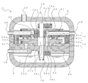
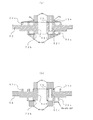
- FIG. 1 is a schematic cross-sectional view showing the structure of a scroll expander according to an embodiment of the present invention.
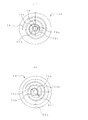
- FIG. 2 is a plan view showing the swing scroll of the scroll expander. 2A shows the swing scroll 52 viewed from the sub-compression mechanism 3 side, and FIG. 2B shows the swing scroll 52 viewed from the expansion mechanism 2 side. That is, when the orbiting scroll shown in FIG. 2A is rotated to the right in FIG. 2 and turned over, the state shown in FIG.
- This scroll expander 1 is formed by integrally forming an expansion mechanism 2 and a sub-compression mechanism 3 as a double-sided scroll type that is back-to-back.
- the base plate of the swing scroll of the expansion mechanism 2 and the base plate of the swing scroll of the sub compression mechanism 3 are shared.
- the scroll expander 1 includes a swing scroll 52, a sub compression fixed scroll 61 that constitutes the sub compression mechanism 3, an expansion fixed scroll 51 that constitutes the expansion mechanism 2, and the like.
- the swing scroll 52, the sub compression fixed scroll 61, the expansion fixed scroll 51, and the like are accommodated in the pressure vessel 4.
- an expansion fixed scroll 51 is provided below the swing scroll 52.
- a spiral tooth 51 a is formed on the upper surface portion of the expansion fixed scroll 51, and the expansion fixed scroll 51 is combined with the spiral tooth 51 a of the expansion fixed scroll 51 and the expansion side spiral tooth 52 a on the lower surface side of the swing scroll 52. 51 is arranged.
- the spiral teeth 51 a of the expansion fixed scroll 51 and the expansion side spiral teeth 52 a on the lower surface side of the swing scroll 52 By combining the spiral teeth 51 a of the expansion fixed scroll 51 and the expansion side spiral teeth 52 a on the lower surface side of the swing scroll 52, the spiral teeth 51 a of the expansion fixed scroll 51 and the expansion side spiral teeth on the lower surface side of the swing scroll 52 are combined.
- An expansion chamber is formed between 52a and 52a.
- An Oldham ring 77 is provided between the swing scroll 52 and the expansion fixed scroll 51. The key portion of the Oldham ring 77 is slidably fitted into an Oldham groove 52d formed on the surface of the swing scroll 52 on the side of
- the sub compression mechanism 3 is configured by the upper surface portion of the swing scroll 52 and the sub compression fixed scroll 61
- the expansion mechanism 2 is configured by the lower surface portion of the swing scroll 52 and the expansion fixed scroll 51.
- the outer diameter dimension of the expansion-side spiral tooth 52a is smaller than the outer diameter dimension of the sub-compression side spiral tooth 52c, and the surface on the expansion mechanism 2 side of the orbiting scroll 52.
- the difference between the axial gas load (thrust load) acting on the shaft and the axial gas load acting on the surface of the orbiting scroll 52 on the sub-compression mechanism 3 side is suppressed (see FIG. 2). That is, in the scroll expander 1 according to the present embodiment, the pressure receiving area on the expansion mechanism 2 side of the orbiting scroll 52 is formed smaller than the pressure receiving area on the sub compression mechanism 3 side, and the expansion mechanism 2 of the orbiting scroll 52 is provided. The difference between the axial gas load (thrust load) acting on the surface on the side and the axial gas load acting on the surface on the sub compression mechanism 3 side of the orbiting scroll 52 is suppressed.
- the rotary shaft 78 is provided through the rocking scroll 52, the sub compression fixed scroll 61 and the expansion fixed scroll 51. More specifically, the rotary shaft 78 is inserted into the upper bearing 61b of the sub-compression fixed scroll 61 and the lower bearing 51b of the expansion fixed scroll 51, and is rotatably supported by the upper bearing 61b and the lower bearing 51b.
- the rotating shaft 78 has an eccentric portion 78a inserted into the rocking bearing 52b of the rocking scroll 52, and is rotatably supported by the rocking bearing 52b.
- balancers 79 a and 79 b are installed near both ends of the rotating shaft 78 in order to cancel the unbalance due to the centrifugal force of the orbiting scroll 52.
- An oil pump 76 is provided at the lower end of the rotating shaft 78. As the rotating shaft 78 rotates, the lubricating oil 9 stored in the lower portion of the pressure vessel 4 is sucked into an oil supply hole (not shown) formed in the rotating shaft 78. The lubricating oil 9 sucked into the oil supply hole is supplied to each bearing (the upper bearing 61b, the lower bearing 51b, and the rocking bearing 52b). A part of the lubricating oil 9 supplied to the lower bearing 51 b and the swing bearing 52 b is taken out of the scroll expander 1 together with the refrigerant expanded by the expansion mechanism 2.
- the taken-out lubricating oil 9 returns to the scroll expander 1 (inside the pressure vessel 4) together with the refrigerant sucked into the sub compression mechanism 3.
- an oil return hole 31 that penetrates the sub compression fixed scroll 61 and the expansion fixed scroll 51 in the axial direction of the rotary shaft 78 is formed.
- the pressure vessel 4 of the scroll expander 1 has an expansion suction pipe 15 that allows (intakes) refrigerant into the expansion chamber of the expansion mechanism 2, an expansion / discharge pipe 16 that flows out (discharges) refrigerant expanded in the expansion chamber, and a sub compression mechanism.
- a sub-compression suction pipe 19 that guides the refrigerant that sucks the refrigerant into the pressure chamber 4 and a sub-compression discharge pipe 20 that discharges the refrigerant compressed in the compression chamber are provided in the compression chamber 3. More specifically, a high-pressure introduction hole 52f that penetrates in the axial direction of the rotary shaft 78 (in other words, from the sub compression mechanism 3 side to the expansion mechanism 2 side) is formed in the base plate of the orbiting scroll 52.
- the sub-compression fixed scroll 61 is formed with an expansion suction hole 35 communicating with the high-pressure introduction hole 52f.
- the expansion suction pipe 15 communicates with the expansion suction hole 35, and the refrigerant flowing into the expansion suction pipe 15 flows into the expansion chamber of the expansion mechanism 2 through the expansion suction hole 35 and the high pressure introduction hole 52f.
- the scroll expander 1 is provided with eccentric seals 72a and 72b and a concentric seal 73.
- a rocking bearing 52 b into which the eccentric part 78 a of the rotating shaft 78 is inserted is provided at the center of the rocking scroll 52.
- so-called bulbous portions are formed on both sides of the orbiting scroll 52 at the center (the inner peripheral end side of the expansion side spiral tooth 52a and the inner peripheral end side of the sub compression side spiral tooth 52c).
- the eccentric seal 72 a and the concentric seal 73 are provided on the bulb-shaped portion on the upper surface side (sub compression mechanism 3 side) of the swing scroll 52. That is, a portion between the eccentric seal 72a and the concentric seal 73 is a high pressure receiving area portion.
- the eccentric seal 72a corresponds to the first seal portion in the present invention
- the concentric seal 73 corresponds to the second seal portion in the present invention.
- the concentric seal 73 is disposed concentrically with, for example, the rocking bearing 52b (in other words, the eccentric portion 78a of the rotating shaft 78).
- the eccentric seal 72a is provided, for example, in the vicinity of the outer peripheral portion of the bulb-shaped portion. Since the bulb-shaped portion on the upper surface side (the sub compression mechanism 3 side) of the swing scroll 52 is formed corresponding to the shape of the sub compression side spiral tooth 52c, the center position of the eccentric seal 72a is the center position of the concentric seal 73. It is an eccentric position. That is, the concentric seal 73 seals the high pressure receiving area portion that becomes a high pressure environment and the vicinity of the rocking bearing 52b that becomes the low pressure environment of the atmosphere in the pressure vessel 4.
- the eccentric seal 72a seals the high pressure receiving area portion that becomes a high pressure environment and the compression chamber that becomes an environment of intermediate pressure.
- the high-pressure introduction hole 52 f opens at a position where the distance between the eccentric seal 72 a and the concentric seal 73 is the longest.
- the eccentric seal 72b is provided on the bulb-shaped portion on the lower surface side (the expansion mechanism 2 side) of the orbiting scroll 52.
- the eccentric seal 72b is provided in the vicinity of the outer peripheral portion of the bulb-shaped portion, for example.
- the eccentric seal 72b seals the vicinity of the rocking bearing 52b that becomes the low pressure environment of the atmosphere in the pressure vessel 4 and the expansion chamber (more specifically, the expansion chamber in the innermost peripheral portion) that becomes the high pressure environment.
- the scroll expander 1 configured in this manner operates as follows during steady operation.
- the high-pressure refrigerant that has flowed in from the expansion suction pipe 15 flows into (inhales) the expansion chamber on the central portion side through the expansion suction hole 35 and the high-pressure introduction hole 52f, and expands.
- the orbiting scroll 52 performs an orbiting motion by power when the refrigerant expands in the expansion chamber.
- the sub compression mechanism 3 the low pressure refrigerant is sucked into the compression chamber from the sub compression suction pipe 19 through the suction port (not shown for another phase cross section), and the pressure is increased.
- the refrigerant whose pressure has been increased to the intermediate pressure pushes the discharge valve 32 open from the discharge port and is discharged to the sub-compression discharge pipe 20. Note that the refrigerant after expansion in the expansion chamber is discharged from the expansion discharge pipe 16.
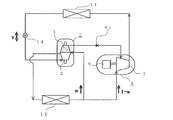
- FIG. 3 is a circuit configuration diagram showing an example of the refrigeration cycle apparatus according to the embodiment of the present invention.
- a main compressor 5 in which a main compression mechanism 7 is driven by a motor 6 and a sub drive driven by power recovered by an expansion mechanism 2.
- a compression mechanism 3 The refrigerant suction port of the main compressor 5 (that is, the main compression mechanism 7) and the refrigerant suction port (the sub compression suction pipe 19 shown in FIG. 1) of the sub compression mechanism 3 are connected in parallel to the refrigerant outlet of the evaporator 12. ing. Further, the refrigerant discharge port (sub compression discharge pipe 20 shown in FIG.
- the refrigerant discharge port of the main compressor 5 (that is, the main compression mechanism 7) is connected to the refrigerant inlet of the gas cooler 11, and the refrigerant outlet of the gas cooler 11 is connected to the refrigerant flow of the expansion mechanism 2 via the pre-expansion valve 14. It is connected to an inlet (an expansion suction pipe 15 shown in FIG. 1). Further, the refrigerant outlet (expansion / discharge pipe 16 shown in FIG. 1) of the expansion mechanism 2 is connected to the refrigerant inlet of the evaporator 12.
- the sub-compression mechanism 3 is operated, so that the refrigerant flowing out of the evaporator 12 is transferred to the sub-compression mechanism 3 and the main compressor 5 by w: (1-w ).
- the refrigerant specific volume at the inlet of the expansion mechanism 2 is vexi
- the refrigerant specific volume at the sub compression inlet is vs
- (suction volume of the expansion mechanism 2) / (suction volume of the sub compression mechanism 3) is ⁇ vEC *
- w The flow rate of the expansion mechanism 2 and the sub-compression mechanism 3 can be matched by adjusting the suction amount (rotation speed) of the main compressor 5 so that becomes 1 / ⁇ vEC * ⁇ (vexi / vs).
- the sub-compression mechanism 3 compresses the refrigerant having the branching ratio w from the low pressure Pl to the intermediate pressure Pm corresponding to the recovered power, and returns the additional compression from the intermediate pressure Pm to the high pressure Ph to the main compressor 5 to return to the motor.
- the power of the expansion mechanism 2 and the sub-compression mechanism 3 can be balanced.
- the scroll expander 1 matches the flow rate by the flow ratio between the main compressor 5 (that is, the main compression mechanism 7) and the sub compression mechanism 3, and the main compressor 5 (that is, the main compressor 5). Power matching is achieved by additional compression in the compression mechanism 7).
- a pre-expansion valve 14 is described. This is for controlling the pressure on the expansion mechanism 2 side at the time of transition such as start-up. It has become.
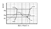
- FIG. 4 shows the operating state during steady operation of the refrigeration cycle apparatus according to the present embodiment on the Mollier diagram of the refrigerant pressure P on the vertical axis and the specific enthalpy h on the horizontal axis.
- the enthalpy difference (hexi-hexo) before and after the expansion mechanism 2 corresponds to energy recovered as power, and this power is used as power of cs ⁇ c2d for sub-compressing the flow rate w to the intermediate pressure Pm. .
- cs ⁇ c1d compression for the flow rate (1-w) and additional compression c2d ⁇ c1d for the flow rate w are performed.
- the enthalpy at the inlet of the evaporator 12 is equal to hexi.
- an increase of (enthalpy difference hexi ⁇ hexo) ⁇ (flow rate 1) as refrigeration capacity and an input of (enthalpy difference hc2d ⁇ hcs) ⁇ (flow rate w) is C.I. O. P. It will contribute to improvement.
- the diversion ratio w is determined in accordance with the suction volume ratio ⁇ vEC * of the scroll expander 1, and the ratio of the enthalpy difference between the expansion mechanism 2 side and the sub compression mechanism 3 side (hexi-hexo) / (hc2d-hcs) Is equal to the diversion ratio w, the level of the intermediate pressure Pm depends on ⁇ vEC * .
- the refrigerant on the expansion mechanism 2 side and the refrigerant on the sub-compression mechanism 3 side flow into the same pressure vessel 4, and exchange power due to the refrigerant pressure (gas pressure).
- the load between the expansion mechanism 2 and the sub-compression mechanism 3 (the difference between the load applied to the orbiting scroll 52 from the expansion mechanism 2 side and the load applied to the orbiting scroll 52 from the sub-compression mechanism 3 side) or the expansion mechanism 2
- the pressure and temperature of the refrigerant (c2d position shown in FIG. 4) discharged by the sub-compression mechanism 3 can be adjusted by setting ⁇ vEC * .
- the intermediate pressure Pm is approximately (high pressure Ph + low pressure Pl) / 2 or less.
- the suction volume ratio ⁇ vEC * is set so that the internal heat leak (heat leak between the refrigerant in the expansion chamber and the refrigerant in the compression chamber) generated at the center portion of the base plate of the swing scroll becomes an allowable level
- the intermediate pressure Pm is approximately (high pressure Ph + low pressure Pl) / 2 or less.
- the high-pressure refrigerant of the expansion mechanism (more specifically, the expansion chamber) is sublimated.
- a method of increasing the thrust load acting on the surface of the orbiting scroll on the sub-compression mechanism side by guiding it to the central portion on the compression mechanism side and balancing it with the thrust load acting on the surface of the orbiting scroll on the expansion mechanism side is considered. It is done.
- the conventional scroll expander 101 is formed such that the outer diameter dimension of the expansion side spiral tooth 52a is smaller than the outer diameter dimension of the sub-compression side spiral tooth 52c.
- the conventional scroll expander 101 uses the high-pressure introduction hole 52e that penetrates the swing scroll 52 in the axial direction to subsist the high-pressure refrigerant before expansion on the inlet side of the expansion mechanism 2 (immediately after being sucked into the expansion chamber). It acts on the central part of the compression mechanism 3. That is, the opening on the expansion mechanism 2 side of the high-pressure introduction hole 52e is opened in the innermost peripheral portion of the expansion chamber. The opening of the high-pressure introduction hole 52e on the sub-compression mechanism 3 side opens to a high-pressure receiving area portion partitioned by the eccentric seal 72a and the concentric seal 73. Thereby, a high pressure acts on the high-pressure receiving area part divided by the concentric seal 73 and the eccentric seal 72a.
- the state of the thrust load acting on the orbiting scroll at this time is schematically shown in FIG. 8 using the low pressure Pl as the reference pressure.
- FIG. 8 (a) shows the situation when the sealing performance of the eccentric seal 72a and the concentric seal 73 that form the high pressure pressure receiving area portion is maintained during steady operation.
- the high pressure Ph to the low pressure Pl act on the spiral tooth portion (expansion chamber) outside the eccentric seal 72b.
- the low pressure Pl acts from the intermediate pressure Pm to the spiral tooth portion (compression chamber) outside the eccentric seal 72a.
- the high-pressure Ph of the refrigerant guided from the expansion mechanism 2 side through the high-pressure introduction hole 52e acts on the high-pressure receiving area (between the eccentric seal 72a and the concentric seal 73). Yes.
- FIG. 8A shows the situation when the sealing performance of the eccentric seal 72a and the concentric seal 73 that form the high pressure pressure receiving area portion is maintained during steady operation.
- the high pressure Ph to the low pressure Pl act on the spiral tooth portion (expansion chamber) outside the eccentric seal 72b.
- the low pressure Pl acts from the intermediate pressure Pm to the spiral tooth portion (compression chamber) outside the eccentric seal 72
- the pressure change in the expansion chamber and the pressure change in the compression chamber are simply shown as a gradient pressure distribution from the central portion to the outer peripheral side. Due to the action of the high pressure Ph of the refrigerant guided from the high pressure introduction hole 52e on the high pressure receiving area portion on the sub compression mechanism 3 side, the thrust load acting on the swing scroll 52 from the expansion mechanism 2 side in total, and the sub compression mechanism 3 The thrust load acting on the orbiting scroll 52 from the side is generally balanced.
- FIG. 8 (b) is different from FIG. 8 (b) in that the sealability of the eccentric seal 72a and / or the concentric seal 73 forming the high pressure receiving area part is incomplete, and refrigerant leaks from the high pressure receiving area part. Indicates the situation. In such a situation, a leakage flow path is formed from the high pressure introduction hole 52e to the outside of the eccentric seal 72a or the inside of the concentric seal 73 through the pressure receiving area portion. Then, pressure loss occurs in the high-pressure introduction hole 52e, the eccentric seal 72a, or the concentric seal 73 in accordance with the refrigerant flow rate from the leakage flow path.
- FIG. 8C shows such a stop state. Since the sub compression mechanism 3 does not perform sub compression, the low pressure Pl from the intermediate pressure Pm does not act on the spiral tooth portion (compression chamber) outside the eccentric seal 72a on the sub compression mechanism 3 side. For this reason, the thrust load that acts on the orbiting scroll 52 from the sub-compression mechanism 3 side is only the amount (Ph ⁇ P 2 ) that acts on the high pressure pressure receiving area (between the eccentric seal 72a and the concentric seal 73). On the other hand, on the expansion mechanism 2 side, a pressure that is lower by the pressure loss ⁇ P ′′ due to the increased leakage flow rate from the tip clearance acts on the expansion chamber one outside from the central portion. In the stopped state shown in FIG.
- the unexpanded refrigerant that has flowed into the expansion suction hole 35 is formed on the surface of the orbiting scroll 52 on the side of the sub-compression mechanism 3 on the high pressure receiving area portion ( After passing through the eccentric seal 72a and the concentric seal 73), the high pressure introduction hole 52f flows into the expansion chamber of the expansion mechanism 2 (more specifically, the expansion chamber on the center side). That is, unlike the high-pressure introduction hole 52e of the conventional scroll expander 101 shown in FIG. 6, the high-pressure introduction hole 52f of the scroll expander 1 according to the present embodiment is simply a high-pressure pressure receiving area (concentric with the eccentric seal 72a).
- the high-pressure introduction hole 52f of the scroll expander 1 has a corresponding port diameter (opening diameter).
- the high-pressure introduction hole 52f of the scroll expander 1 has a larger port diameter (opening diameter) than the high-pressure introduction hole 52e of the conventional scroll expander 101 shown in FIG.
- the opening position of the high-pressure introduction hole 52f on the sub-compression mechanism 3 side is the optimum position so that it is concentric with the eccentric seal 72a. 73 is the farthest position.
- expansion-side spiral teeth 52a and the sub-compression-side spirals formed in the orbiting scroll 52 so that the opening position of the high-pressure introduction hole 52f on the expansion mechanism 2 side (opening position in the high-pressure receiving area portion) is an optimal position.
- the phase of the teeth 52c is different from that of the conventional scroll expander 101 shown in FIG.
- the thrust load acting on the orbiting scroll 52 is as shown in FIG.
- FIG. 5 (a) shows a situation when the sealability of the eccentric seal 72a and the concentric seal 73 that form the high pressure pressure receiving area portion is maintained during steady operation.
- high pressure Ph acts on the high pressure receiving area (between the eccentric seal 72a and the concentric seal 73) on the sub compression mechanism 3 side.
- the low pressure Pl acts from the intermediate pressure Pm to the spiral tooth portion (compression chamber) outside the eccentric seal 72a.
- a pressure loss (Ph ⁇ P 1 ) which is reduced by the passage of the high-pressure introduction hole 52f from the high pressure Ph, acts on the inner peripheral side of the spiral tooth portion (expansion chamber) outside the eccentric seal 72b.
- a low pressure Pl acts on the outer peripheral side of the spiral tooth portion (expansion chamber) outside the eccentric seal 72b. That is, on the expansion mechanism 2 side, the low pressure Pl acts from the eccentric seal 72b to the outer spiral tooth portion (expansion chamber) from (Ph ⁇ P 1 ).
- the thrust load that acts on the orbiting scroll 52 from the expansion mechanism 2 side and the thrust load that acts on the orbiting scroll 52 from the sub-compression mechanism 3 side are substantially balanced.
- the pressure before and after the high-pressure introduction hole that is, acts near the expansion mechanism 2 side opening and near the sub compression mechanism 3 side opening. Let's focus on the pressure.
- the high pressure Ph acts in the vicinity of the opening of the high pressure introduction hole 52f on the sub compression mechanism 3 side in both states of FIGS.
- the suction flow rate of high pressure is introduced near the opening on the expansion mechanism 2 side of the high pressure introduction hole 52f.
- the pressure before and after the high-pressure introduction hole is (expansion mechanism 2 side) ⁇ (sub compression mechanism 3 side) in the conventional scroll expander 101, whereas in the scroll expander 1 according to the present embodiment, (Expansion mechanism 2 side) ⁇ (Sub compression mechanism 3 side).
- the high pressure introduction hole 52f also serves as a suction path from the fine hole for simple pressure introduction to the expansion chamber, so that the differential pressure before and after the high pressure introduction hole 52f is It always acts in the direction in which the tip of the spiral tooth on the expansion mechanism 2 side is pressed.
- the conventional scroll expander 101 When the operation as the scroll expander is stopped for some reason, the conventional scroll expander 101 is in the state shown in FIG. 8C, and the scroll expander 1 according to the present embodiment is in the state shown in FIG. Become. That is, when the operation as the scroll expander is stopped for some reason, the conventional scroll expander 101 has a large clearance formed at the tip of the spiral tooth on the expansion mechanism 2 side, and therefore the spiral tooth on the expansion mechanism 2 side.
- the pressure loss ⁇ P ′′ due to the flow rate of leakage from the tip clearance is less likely to occur than when the tip of the tip is pressed.
- the pressure (Ph ⁇ P ′′) becomes close to the high pressure Ph, and the thrust load acting from the expansion mechanism 2 side to the sub-compression mechanism 3 side tends to increase.
- the scroll expander 1 according to the present embodiment since the tip of the spiral tooth on the expansion mechanism 2 side is easily pressed, leakage from the tooth tip clearance of the spiral tooth on the expansion mechanism 2 side.
- the pressure loss ⁇ P ′ due to the flow rate becomes relatively large. For this reason, in the scroll expander 1 according to the present embodiment, the thrust load acting on the orbiting scroll 52 can be hardly applied from the expansion mechanism 2 side to the sub compression mechanism 3 side.
- the high-pressure introduction hole 52e is formed as a pore whose upstream side of the refrigerant flow is on the expansion mechanism 2 side
- the pressing force at the tip of the spiral tooth on the sub-compression mechanism 3 side becomes excessive, and a transition is made to a stopped state. It is easy and it is difficult to return from the stopped state.
- the high-pressure introduction hole 52f is formed as a through-hole that also serves as a suction path to the expansion mechanism 2 and is upstream of the refrigerant flow on the sub-compression mechanism 3 side, It is difficult to fall into a state, and it is easy to return even when it is stopped.
- the scroll expander 1 and the refrigeration cycle apparatus 100 using the scroll expander 1 according to the present embodiment can operate stably regardless of the sealing property of the high pressure receiving area.
Landscapes
- Engineering & Computer Science (AREA)
- Mechanical Engineering (AREA)
- General Engineering & Computer Science (AREA)
- Physics & Mathematics (AREA)
- Thermal Sciences (AREA)
- Rotary Pumps (AREA)
Abstract
Un détendeur à spirale (1) est équipé d'un mécanisme d'expansion (2) du type à spirale qui récupère la puissance motrice tout en dilatant un fluide frigorigène s'écoulant dans une chambre d'expansion, et d'un sous-mécanisme de compression (3) du type à spirale qui comprime le fluide frigorigène aspiré dans une chambre de compression à l'aide de la puissance motrice récupérée par le mécanisme d'expansion (2), le mécanisme d'expansion (2) et le sous-mécanisme de compression (3) étant formés d'un seul bloc, dos à dos. Un trou de passage haute-pression (52f) qui pénètre depuis le côté sous-mécanisme de compression (3) jusqu'au côté mécanisme d'expansion (2) est formé dans la spirale oscillante (52) du détendeur à spirale (1) en tant que voie d'écoulement pour fluide frigorigène qui guide le fluide frigorigène jusqu'à la chambre d'expansion du mécanisme d'expansion (2), et le fluide frigorigène qui s'écoule dans la chambre d'expansion du mécanisme d'expansion (2) s'écoule dans le trou de passage haute-pression (52f) depuis le côté sous-mécanisme de compression (3), et est guidé jusqu'à la chambre d'expansion.
Priority Applications (2)
| Application Number | Priority Date | Filing Date | Title |
|---|---|---|---|
| JP2013517691A JP5523629B2 (ja) | 2011-05-31 | 2011-05-31 | スクロール膨張機及び冷凍サイクル装置 |
| PCT/JP2011/003028 WO2012164609A1 (fr) | 2011-05-31 | 2011-05-31 | Détendeur à spirale et dispositif à cycle de réfrigération |
Applications Claiming Priority (1)
| Application Number | Priority Date | Filing Date | Title |
|---|---|---|---|
| PCT/JP2011/003028 WO2012164609A1 (fr) | 2011-05-31 | 2011-05-31 | Détendeur à spirale et dispositif à cycle de réfrigération |
Publications (1)
| Publication Number | Publication Date |
|---|---|
| WO2012164609A1 true WO2012164609A1 (fr) | 2012-12-06 |
Family
ID=47258506
Family Applications (1)
| Application Number | Title | Priority Date | Filing Date |
|---|---|---|---|
| PCT/JP2011/003028 Ceased WO2012164609A1 (fr) | 2011-05-31 | 2011-05-31 | Détendeur à spirale et dispositif à cycle de réfrigération |
Country Status (2)
| Country | Link |
|---|---|
| JP (1) | JP5523629B2 (fr) |
| WO (1) | WO2012164609A1 (fr) |
Cited By (3)
| Publication number | Priority date | Publication date | Assignee | Title |
|---|---|---|---|---|
| CN105508241A (zh) * | 2015-12-22 | 2016-04-20 | 珠海格力节能环保制冷技术研究中心有限公司 | 一种涡旋压缩机及其控制方法 |
| DE102016105390A1 (de) | 2015-03-23 | 2016-09-29 | Hitachi Plant Mechanics Co., Ltd. | Wasserstoff-Vorkühlsystem |
| JP2016538455A (ja) * | 2013-10-28 | 2016-12-08 | グリー グリーン リフリジレーション テクノロジー センター カンパニー リミテッド オブ ズーハイGree Green Refrigeration Technology Center Co., Ltd. Of Zhuhai | 膨張圧縮機装置及びそれを備えるエアコン |
Citations (5)
| Publication number | Priority date | Publication date | Assignee | Title |
|---|---|---|---|---|
| JPS58217163A (ja) * | 1982-06-10 | 1983-12-17 | 株式会社前川製作所 | 圧縮式冷凍サイクルの冷凍能力増加装置 |
| JP2007192508A (ja) * | 2006-01-20 | 2007-08-02 | Mitsubishi Electric Corp | スクロール膨張機 |
| JP2008248823A (ja) * | 2007-03-30 | 2008-10-16 | Mitsubishi Electric Corp | スクロール流体機械 |
| JP4584306B2 (ja) * | 2005-03-29 | 2010-11-17 | 三菱電機株式会社 | スクロール膨張機 |
| WO2011036741A1 (fr) * | 2009-09-24 | 2011-03-31 | 三菱電機株式会社 | Dispositif à cycle de réfrigération |
-
2011
- 2011-05-31 WO PCT/JP2011/003028 patent/WO2012164609A1/fr not_active Ceased
- 2011-05-31 JP JP2013517691A patent/JP5523629B2/ja not_active Expired - Fee Related
Patent Citations (5)
| Publication number | Priority date | Publication date | Assignee | Title |
|---|---|---|---|---|
| JPS58217163A (ja) * | 1982-06-10 | 1983-12-17 | 株式会社前川製作所 | 圧縮式冷凍サイクルの冷凍能力増加装置 |
| JP4584306B2 (ja) * | 2005-03-29 | 2010-11-17 | 三菱電機株式会社 | スクロール膨張機 |
| JP2007192508A (ja) * | 2006-01-20 | 2007-08-02 | Mitsubishi Electric Corp | スクロール膨張機 |
| JP2008248823A (ja) * | 2007-03-30 | 2008-10-16 | Mitsubishi Electric Corp | スクロール流体機械 |
| WO2011036741A1 (fr) * | 2009-09-24 | 2011-03-31 | 三菱電機株式会社 | Dispositif à cycle de réfrigération |
Cited By (4)
| Publication number | Priority date | Publication date | Assignee | Title |
|---|---|---|---|---|
| JP2016538455A (ja) * | 2013-10-28 | 2016-12-08 | グリー グリーン リフリジレーション テクノロジー センター カンパニー リミテッド オブ ズーハイGree Green Refrigeration Technology Center Co., Ltd. Of Zhuhai | 膨張圧縮機装置及びそれを備えるエアコン |
| DE102016105390A1 (de) | 2015-03-23 | 2016-09-29 | Hitachi Plant Mechanics Co., Ltd. | Wasserstoff-Vorkühlsystem |
| CN105508241A (zh) * | 2015-12-22 | 2016-04-20 | 珠海格力节能环保制冷技术研究中心有限公司 | 一种涡旋压缩机及其控制方法 |
| CN105508241B (zh) * | 2015-12-22 | 2017-11-24 | 珠海格力节能环保制冷技术研究中心有限公司 | 一种涡旋压缩机及其控制方法 |
Also Published As
| Publication number | Publication date |
|---|---|
| JPWO2012164609A1 (ja) | 2014-07-31 |
| JP5523629B2 (ja) | 2014-06-18 |
Similar Documents
| Publication | Publication Date | Title |
|---|---|---|
| US8074471B2 (en) | Refrigeration cycle apparatus and fluid machine used for the same | |
| CN101165350B (zh) | 涡旋压缩机 | |
| CN100570238C (zh) | 冷冻空调装置 | |
| JPWO2014156743A1 (ja) | スクロール圧縮機及びそれを備えた冷凍サイクル装置 | |
| JP2011027076A (ja) | スクロール圧縮機 | |
| JPWO2009130929A1 (ja) | 冷凍空気調和装置 | |
| JP2004137979A (ja) | 膨張機 | |
| JP5523629B2 (ja) | スクロール膨張機及び冷凍サイクル装置 | |
| JPWO2012029203A6 (ja) | 膨張機および冷凍サイクル装置 | |
| JPWO2012029203A1 (ja) | 膨張機および冷凍サイクル装置 | |
| JP4974851B2 (ja) | 冷凍空調装置 | |
| JP4924092B2 (ja) | 冷凍サイクル装置 | |
| JPWO2012042698A1 (ja) | 冷凍空調装置 | |
| JP2010150926A (ja) | スクロール膨張機及びそれを備えた冷凍空調装置 | |
| US8128388B2 (en) | Scroll-type expansion machine | |
| JP4555231B2 (ja) | スクロール膨張機 | |
| WO2011083510A1 (fr) | Dispositif de cyclage de réfrigération et détendeur installé dans celui-ci | |
| JP5488443B2 (ja) | スクロール圧縮機 | |
| JP2006220143A (ja) | 容積形流体機械及びそれを用いた冷凍サイクル | |
| WO2013160953A1 (fr) | Dispositif d'expansion doté d'un mécanisme de compression intégré | |
| JP5247752B2 (ja) | 冷凍サイクル装置 | |
| WO2012104934A1 (fr) | Détendeur en spirale, et cycle de réfrigération comportant le détendeur en spirale | |
| JP4929051B2 (ja) | 密閉形スクロール圧縮機及び冷凍空調装置 | |
| JP2011237086A (ja) | 冷凍空調装置 | |
| JP5484604B2 (ja) | 冷凍空調装置 |
Legal Events
| Date | Code | Title | Description |
|---|---|---|---|
| 121 | Ep: the epo has been informed by wipo that ep was designated in this application |
Ref document number: 11867097 Country of ref document: EP Kind code of ref document: A1 |
|
| ENP | Entry into the national phase |
Ref document number: 2013517691 Country of ref document: JP Kind code of ref document: A |
|
| NENP | Non-entry into the national phase |
Ref country code: DE |
|
| 122 | Ep: pct application non-entry in european phase |
Ref document number: 11867097 Country of ref document: EP Kind code of ref document: A1 |