WO2012164663A1 - レーザ加工ヘッド、レーザ加工装置、レーザ加工装置の光学系、レーザ加工方法、及びレーザ集束方法 - Google Patents
レーザ加工ヘッド、レーザ加工装置、レーザ加工装置の光学系、レーザ加工方法、及びレーザ集束方法 Download PDFInfo
- Publication number
- WO2012164663A1 WO2012164663A1 PCT/JP2011/062391 JP2011062391W WO2012164663A1 WO 2012164663 A1 WO2012164663 A1 WO 2012164663A1 JP 2011062391 W JP2011062391 W JP 2011062391W WO 2012164663 A1 WO2012164663 A1 WO 2012164663A1
- Authority
- WO
- WIPO (PCT)
- Prior art keywords
- laser beam
- laser
- workpiece
- lens
- intensity distribution
- Prior art date
- Legal status (The legal status is an assumption and is not a legal conclusion. Google has not performed a legal analysis and makes no representation as to the accuracy of the status listed.)
- Ceased
Links
Images


Classifications
-
- B—PERFORMING OPERATIONS; TRANSPORTING
- B23—MACHINE TOOLS; METAL-WORKING NOT OTHERWISE PROVIDED FOR
- B23K—SOLDERING OR UNSOLDERING; WELDING; CLADDING OR PLATING BY SOLDERING OR WELDING; CUTTING BY APPLYING HEAT LOCALLY, e.g. FLAME CUTTING; WORKING BY LASER BEAM
- B23K26/00—Working by laser beam, e.g. welding, cutting or boring
- B23K26/02—Positioning or observing the workpiece, e.g. with respect to the point of impact; Aligning, aiming or focusing the laser beam
- B23K26/06—Shaping the laser beam, e.g. by masks or multi-focusing
- B23K26/064—Shaping the laser beam, e.g. by masks or multi-focusing by means of optical elements, e.g. lenses, mirrors or prisms
- B23K26/0648—Shaping the laser beam, e.g. by masks or multi-focusing by means of optical elements, e.g. lenses, mirrors or prisms comprising lenses
-
- B—PERFORMING OPERATIONS; TRANSPORTING
- B23—MACHINE TOOLS; METAL-WORKING NOT OTHERWISE PROVIDED FOR
- B23K—SOLDERING OR UNSOLDERING; WELDING; CLADDING OR PLATING BY SOLDERING OR WELDING; CUTTING BY APPLYING HEAT LOCALLY, e.g. FLAME CUTTING; WORKING BY LASER BEAM
- B23K26/00—Working by laser beam, e.g. welding, cutting or boring
- B23K26/02—Positioning or observing the workpiece, e.g. with respect to the point of impact; Aligning, aiming or focusing the laser beam
- B23K26/06—Shaping the laser beam, e.g. by masks or multi-focusing
- B23K26/0665—Shaping the laser beam, e.g. by masks or multi-focusing by beam condensation on the workpiece, e.g. for focusing
-
- B—PERFORMING OPERATIONS; TRANSPORTING
- B23—MACHINE TOOLS; METAL-WORKING NOT OTHERWISE PROVIDED FOR
- B23K—SOLDERING OR UNSOLDERING; WELDING; CLADDING OR PLATING BY SOLDERING OR WELDING; CUTTING BY APPLYING HEAT LOCALLY, e.g. FLAME CUTTING; WORKING BY LASER BEAM
- B23K26/00—Working by laser beam, e.g. welding, cutting or boring
- B23K26/02—Positioning or observing the workpiece, e.g. with respect to the point of impact; Aligning, aiming or focusing the laser beam
- B23K26/06—Shaping the laser beam, e.g. by masks or multi-focusing
- B23K26/073—Shaping the laser spot
- B23K26/0734—Shaping the laser spot into an annular shape
-
- B—PERFORMING OPERATIONS; TRANSPORTING
- B23—MACHINE TOOLS; METAL-WORKING NOT OTHERWISE PROVIDED FOR
- B23K—SOLDERING OR UNSOLDERING; WELDING; CLADDING OR PLATING BY SOLDERING OR WELDING; CUTTING BY APPLYING HEAT LOCALLY, e.g. FLAME CUTTING; WORKING BY LASER BEAM
- B23K26/00—Working by laser beam, e.g. welding, cutting or boring
- B23K26/36—Removing material
- B23K26/38—Removing material by boring or cutting
-
- G—PHYSICS
- G02—OPTICS
- G02B—OPTICAL ELEMENTS, SYSTEMS OR APPARATUS
- G02B27/00—Optical systems or apparatus not provided for by any of the groups G02B1/00 - G02B26/00, G02B30/00
- G02B27/40—Optical focusing aids
Definitions
- the present invention relates to a laser processing head, a laser processing apparatus, an optical system of the laser processing apparatus, a laser processing method, and a laser focusing method.
- a laser beam is sent from a laser oscillator to a machining head for machining a metal or alloy workpiece (workpiece) via an optical fiber, and the development of a laser cutting device that cuts the workpiece by the laser beam has progressed.
- the laser using the optical fiber is a solid laser (for example, a fiber laser, a disk laser, a semiconductor laser, etc.) that is transmitted using the optical fiber.
- Patent Document 1 discloses a condensing optical system that condenses a laser beam generated by a laser light source at a desired focal depth.
- a condensing optical system configured to generate spherical aberration is described.
- the quality of the laser beam tends to be better in the central area than the peripheral area (higher straightness), and the quality is worse as the distance from the central area increases. Therefore, when cutting the workpiece, the laser beam in the peripheral area with poor quality will come into contact with the cutting edge of the workpiece, affecting the cutting quality (cutting accuracy, roughness, etc.). It becomes.
- the thick severe mm or more, for example more than 8 mm
- Patent Document 2 an energy density distribution having a Gaussian distribution in a cross section of a laser beam is measured on the inside and outside of a plane including the optical axis of the laser beam by an internal / external reversal optical system including two cylindrical lens pairs.
- a reversing laser processing device is described.
- the pair of cylindrical lenses arranged on the upstream side in the traveling direction of the laser beam is a lens pair in which two cylindrical lenses having the same shape are bonded in parallel.
- the arranged cylindrical lens pair is a lens pair in which two cylindrical lenses are arranged in parallel and spaced apart from each other, and collimates the laser beam divided into two by the upstream cylindrical lens pair and enters the condenser lens.
- the laser processing apparatus described in Patent Document 2 reverses the energy density distribution having a Gaussian distribution on the inside and outside of the plane including the optical axis of the laser beam. Will be in contact with the workpiece.
- the cross section of the laser beam at the position of the workpiece is not circular, so that the workpiece is processed only in the direction in which the laser beam is in contact with the workpiece. I can't process things. That is, in the laser processing apparatus described in Patent Document 2, the direction in which the workpiece can be processed is limited.
- the laser beam is divided by two cylindrical lens pairs, and after being reversed inside and outside, the laser beam is condensed on one point of the workpiece by the condenser lens. For this reason, the configuration of the optical system is very complicated.
- the optical axis of the laser beam before the division and the optical axes of the two divided laser beams are adjusted, and the two divided laser beams are placed on the workpiece. It is necessary to focus at the same position, and it is very difficult to adjust the optical axis.
- the present invention has been made in view of such circumstances, and with a simple configuration, can generate a laser beam that is reversed inside and outside at the position of the workpiece, and has a machining direction in machining the workpiece. It is an object to provide a laser processing head, a laser processing apparatus, an optical system of the laser processing apparatus, a laser processing method, and a laser focusing method that are not limited.
- the laser processing head, laser processing apparatus, optical system of the laser processing apparatus, laser processing method, and laser focusing method of the present invention employ the following means.
- a laser processing apparatus is a laser processing head provided in a laser processing apparatus that processes a workpiece by irradiating a laser beam, and includes a spherical lens and a spherical surface for condensing the laser beam. Due to at least one of the aspherical lenses capable of generating aberrations, the laser beam intensity distribution is higher in the peripheral region than in the central region at the position of the workpiece, and the focal point position of the workpiece is The workpiece is irradiated with the laser beam shifted from the position.
- At least one of the spherical lens and the aspherical lens for condensing the laser beam has a caldera shape in which the intensity distribution of the laser beam is higher in the peripheral region than in the central region at the position of the workpiece.
- the workpiece is irradiated with a laser beam whose focal position is deviated from the position of the workpiece.
- the intensity distribution of the laser beam By making the intensity distribution of the laser beam a caldera shape that is higher in the peripheral area than in the central area, the intensity of the side surface of the laser beam in contact with the work piece is increased when machining the work piece, resulting in higher processing accuracy. Can be increased. And, in order to make the intensity distribution in the caldera shape in this way, by using the spherical aberration of the spherical lens or an aspherical lens that is not sufficiently corrected for aberrations (that is, capable of generating spherical aberration), This can be realized by inverting the central region and the peripheral region of the laser beam. In order to perform the inverting, it is necessary to shift the focal position of the laser beam from the position of the workpiece.
- the quality of the laser beam in the central region is better than that in the peripheral region, that is, the straightness is high.
- the straightness is increased, and therefore the distance (depth of focus) at which the beam diameter can be maintained becomes longer, and high-quality processing is possible even for a workpiece having a thickness.
- the laser beam is inverted using the spherical aberration of at least one of the spherical lens and the aspherical lens, and the laser beam is focused in a circular shape, the position of the workpiece can be achieved with a simple configuration.
- the laser beam can be generated by reversing the inside and outside, and the machining direction is not limited in machining the workpiece.
- the laser beam has a ring-shaped intensity distribution at the position of the workpiece.
- the laser beam on the rear side in the processing direction of the workpiece contributes to the temperature rise of the molten metal.
- the laser beam can sufficiently raise the temperature of the molten metal, and can cut even a thick workpiece.
- the laser beam has a non-ring-shaped intensity distribution of the laser beam at the position of the workpiece.
- the non-ring shape is, for example, a circular shape having intensity in the central area as well as in the peripheral area, and is a state in which the intensity distribution of the inverted laser beam is uniform compared to the ring shape.
- the laser beam has a peak in a central region of the intensity distribution at the position of the workpiece.
- the laser beam has a depth of focus of 1 mm or more at the position of the workpiece.
- the center region of the laser beam is better in quality than the peripheral region, that is, has a high straightness.
- the peripheral region of the inverted laser beam has high straightness, so that the depth of focus is increased at the position of the workpiece, and high-quality processing is possible even for a workpiece having a thickness.
- board thickness of a to-be-processed object can be suppressed by making the focal depth of a laser beam into 1 mm or more, processing with higher quality is attained.
- the intensity distribution of the laser beam is higher by 10% or more in the laser beam having the side steepness in the caldera shape than in the laser beam before the caldera shape.
- the laser beam with higher quality is positioned on the side surface, and processing with higher quality becomes possible.
- the spherical lens includes a convex lens positioned on the upstream side in the traveling direction of the laser beam, and a concave lens positioned on the downstream side in the traveling direction of the laser beam from the convex lens, and the convex lens and the concave lens It is preferable that the positional relationship between the focal position of the laser beam and the position where the intensity distribution of the laser beam becomes the caldera shape can be adjusted by changing at least one of the curvatures.
- a laser processing apparatus includes a laser oscillator that oscillates a laser beam, the laser processing head described above that receives the laser beam oscillated by the laser oscillator, and a workpiece. And a stage that moves relative to the laser processing head.
- An optical system of a laser processing apparatus is an optical system of a laser processing apparatus that processes a workpiece by a laser beam oscillated by a laser oscillator, and is an aspherical surface capable of generating a spherical lens and spherical aberration.
- the center region of the laser beam is inverted to the peripheral region at the position of the workpiece, and the peripheral region of the laser beam is moved to the center region at the position of the workpiece.
- the focusing unit causes the central region of the laser beam to be inverted to the peripheral region at the position of the workpiece using the spherical aberration of at least one of the spherical lens and the aspherical lens, and the laser beam
- the peripheral area is inverted to the central area at the position of the workpiece, and the laser beam is focused in a circle. Then, the inverted laser beam will process the workpiece.
- a laser beam has a better quality in the central region than the peripheral region, that is, has a high straightness. For this reason, the peripheral region of the inverted laser beam has high straightness.
- the distance (depth of focus) at which the beam diameter can be maintained becomes long, and high-quality processing is possible even for a workpiece having a thickness.
- the laser beam is inverted using the spherical aberration of at least one of the spherical lens and the aspheric lens, the laser beam in which the inside and outside are reversed at the position of the workpiece with a simple configuration.
- the processing direction is not limited in the processing of the workpiece.
- the laser processing method also includes a spherical lens for oscillating a laser beam for processing a workpiece from a laser oscillator and condensing the oscillated laser beam, and an aspherical surface capable of generating spherical aberration. At least one of the lenses irradiates a laser beam whose intensity distribution has a higher caldera shape in the peripheral area than in the central area and whose focal position is deviated from the position of the work piece. Then, the workpiece is processed while relatively moving the irradiated laser beam and the workpiece.
- the laser focusing method according to the present invention is a laser focusing method of a laser processing apparatus for processing a workpiece by a laser beam oscillated by a laser oscillator, and includes a spherical lens and an aspheric lens capable of generating spherical aberration.
- the central region of the laser beam is inverted to the peripheral region at the position of the workpiece, and the peripheral region of the laser beam is inverted to the central region at the position of the workpiece.
- focusing the laser beam in a circle.
- the present invention it is possible to generate a laser beam whose inside and outside are reversed at the position of the workpiece with a simple configuration, and the machining direction is not limited in the machining of the workpiece.
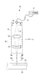
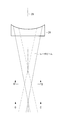
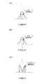
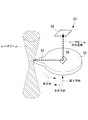
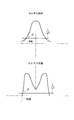
- FIG. 1 It is a schematic diagram which shows the structure of the optical system of the laser cutting device which concerns on embodiment of this invention. It is a figure which shows the light trace of the laser beam which passed the concave lens of the laser cutting device which concerns on embodiment of this invention. It is a schematic diagram showing the intensity distribution at different positions of the laser beam emitted by the laser cutting device according to an embodiment of the present invention, (A) is the intensity distribution of the laser beam immediately after emitted from the laser incident part, (B) is the intensity distribution of the laser beam at the focal position, and (C) is the intensity distribution of the laser beam at a position closer to the workpiece than the focal position. It is a lineblock diagram of an intensity distribution measuring device which measures intensity distribution of a laser beam concerning an embodiment of the present invention.
- FIG. 1 It is a schematic diagram which shows the steepness of the side surface of the laser beam which concerns on embodiment of this invention. It is a schematic diagram which shows intensity distribution of the laser beam in the position of the workpiece which concerns on embodiment of this invention, (A) is a case where intensity distribution is made into ring shape, (B) is intensity distribution in non-ring shape. (C) is a case having a peak in the central region. It is the figure which showed the cut surface of the workpiece by a laser cutting device, (A) is a cut surface of the workpiece by the laser beam before inversion, (B) is the laser cutting which concerns on this embodiment In the apparatus, it is a cut surface of a workpiece by a laser beam that has been inverted.
- the laser processing apparatus according to the present invention will be described as a laser cutting apparatus for cutting a workpiece.
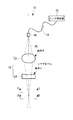
- the laser cutting device 10 includes a laser oscillator 12, an optical fiber 14, a laser processing head 15, and a stage 25.
- the laser cutting device 10 uses a solid laser as the laser oscillator 12.
- the stage 25 is a stage on which the workpiece 20 is placed and moves relative to the laser processing head 15.
- the stage 25 is a so-called XY stage that is movable in the plane direction (X, Y direction) with respect to the laser processing head 15.
- the laser cutting device 10 cuts the workpiece 20 by moving the workpiece 20 or the laser processing head 15 while continuously irradiating the workpiece 20 with the laser beam.
- the workpiece 20 is a metal, and in the present embodiment, the workpiece 20 is an example of carbon steel. Further, the thickness of the workpiece 20 is, for example, several mm (for example, 6 mm to 300 mm, particularly 15 mm to 300 mm) or more. Further, the laser cutting device 10 according to the present embodiment cuts the workpiece 20 while blowing oxygen gas, which is an assist gas, to the cutting portion when cutting the workpiece 20.
- oxygen gas which is an assist gas
- the laser oscillator 12 generates a laser beam (in this embodiment, a fiber laser).
- the laser generated by the laser oscillator 12 is transmitted through the optical fiber 14.
- the laser processing head 15 includes a laser incident portion 16 and an optical system 18.
- the laser incident part 16 is connected to the end of the optical fiber 14 and emits a laser beam transmitted by the optical fiber 14 to the optical system 18.
- the optical system 18 includes a spherical lens.
- the spherical lens includes a condensing lens 22 that is a convex lens positioned on the upstream side in the laser beam traveling direction, and a downstream side in the laser beam traveling direction from the condensing lens 22.
- the condensing lens 22 and the concave lens 24 are arranged so that the central axis 26 is coaxial.
- the condensing lens 22 may be composed of a single lens or a plurality of lenses.
- the condensing lens 22 may convert the laser beam emitted from the optical fiber 14 into parallel light.
- FIG. 2 is a diagram illustrating an example of a light trace of a laser beam that has passed through the concave lens 24 of the laser cutting device 10 according to the embodiment.
- the concave lens 24 has a curvature on the upstream side in the traveling direction of the laser beam, but has no curvature on the downstream side.
- the position where the laser beam incident on the outer side of the concave lens 24 (solid line in FIG. 2) is focused is the position where the laser beam incident on the inner side of the concave lens 24 (broken line in FIG. 2) is collected. It is further downstream than the position where it shines. That is, the concave lens 24 irradiates the surface of the workpiece 20 while condensing and diffusing the laser beam at different positions depending on the incident position.
- the laser beam that has passed through the concave lens 24 diverges on the downstream side where the focal point (position B) is formed as a whole.
- the concave lens 24, which is a spherical lens inverts the laser beam (broken line in FIG. 2) that has been in the central area so far to the peripheral area on the downstream side (workpiece 20 side) from the focal position due to the spherical aberration.
- the laser beam (solid line in FIG. 2) that has been in the peripheral region is inverted to the central region, and the laser beam is focused in a circular shape. That is, the laser cutting device 10 according to the present embodiment uses the concave lens 24 as the final stage of the optical system 18 and inverts the laser beam between the final stage of the optical system 18 and the workpiece.
- FIG. 3 is a schematic diagram showing intensity distributions at different positions of the laser beam emitted from the laser cutting apparatus 10 according to the present embodiment.
- FIG. 3A shows the intensity distribution of the laser beam immediately after being emitted from the laser incident portion 16 (position A in FIG. 1).
- FIG. 3B shows the intensity distribution of the laser beam at the focal position (position B in FIGS. 1 and 2).
- the quality of the laser beam is better in the central region of the laser beam than in the peripheral region (high linearity). That is, the quality of the laser beam in the peripheral region is worse than that in the central region.
- the laser beam in the peripheral area with poor quality comes into contact with the cut end of the workpiece 20, and the quality of cutting (cutting accuracy, roughness, etc.) Will be affected.
- FIG. 3C shows the intensity distribution of the laser beam at a position closer to the workpiece 20 than the focal position (position C in FIGS. 1 and 2).
- the concave lens 24 by the action of the concave lens 24, the laser beam is inverted from the central region to the peripheral region, the laser beam from the peripheral region is inverted to the central region, and the laser beam is focused in a circular shape.
- a high-quality laser beam that is, a laser beam having a long distance (focal depth) capable of maintaining the beam diameter is positioned in the peripheral region because of its high linearity. Become.
- the diameter of the laser beam at the position of the workpiece 20 is set to 0.1 to 2.0 mm.
- FIG. 4 is a configuration diagram of an intensity distribution measuring apparatus 50 that measures the intensity distribution of a laser beam.
- the intensity distribution measuring apparatus 50 includes a scanning unit 54 that scans a laser beam on a part of a circular main body 52.
- the scanning unit 54 is in contact with the laser beam and guides a part of the laser beam to a photodetector 58 (photodiode) provided above the main body 52 via the mirror 56.
- the photodetector 58 outputs the intensity of the detected laser beam.
- the main body 52 can be rotated in the circumferential direction, and can be moved in the height direction and in the left-right direction that crosses the laser beam. By rotating and moving, the laser beam generated by the scanning unit 54 can be obtained. Scan.
- the steepness of the side surface of the intensity distribution of the laser beam emitted from the laser cutting apparatus 10 according to the present embodiment is higher in the caldera-shaped laser beam than in the laser beam before the caldera-shaped. Specifically, it is desirable that the steepness is 10% or more, preferably 20% or more higher than the tangential angle of the side surface. Thereby, a laser beam with higher quality is positioned on the side surface, and processing with higher quality becomes possible. For example, as shown in FIG.
- FIG. 6 is a schematic diagram showing the intensity distribution at the position of the workpiece 20 of the laser beam used in the laser cutting device 10.
- FIG. 6A shows the case where the caldera-like intensity distribution of the laser beam is made more ring-shaped by the above-described inversion.
- the ring shape is a state in which the intensity of the peripheral region is higher than that of the central region of the laser beam, and the intensity of the central region is very small.
- the depth of focus is preferably set as long as possible while maintaining the energy density required for cutting the workpiece 20. Specifically, by setting the focal depth of the laser beam to 1 mm or more, a reduction in energy density within the plate thickness of the workpiece 20 can be suppressed, so that higher quality processing is possible.
- FIG. 6B shows a case where the intensity distribution of the laser beam is made non-ring-shaped by the above-described inversion.
- the non-ring shape is, for example, a circular shape having intensity in the central region as well as in the peripheral region, and is a state in which the intensity distribution of the inverted laser beam is made uniform compared to the ring shape. Even in this case, the quality of the laser beam in the peripheral region is better than that of a laser beam obtained by a conventional condenser lens that corrects aberrations without performing the above-described inversion, and the workpiece can be cut with high quality. .
- FIG. 6C shows a case where the intensity distribution of the laser beam having a peak also in the central region of the intensity distribution at the position of the workpiece 20 is obtained.
- the intensity of the peak in the central area may be larger or smaller than the intensity of the peak in the peripheral area.
- the intensity distribution of the inverted laser beam includes the distance between the laser incident portion 16 and the optical system 18, the distance between the condenser lens 22 and the concave lens 24, the number of condenser lenses 22, and the positions of the condenser lens 22 and the concave lens 24.
- the intensity distributions as shown in FIG. 6 are formed in different shapes.
- FIG. 7 is a view showing a cut surface of the workpiece 20.
- FIG. 7A shows a cut surface of the workpiece 20 by the laser beam before being inverted.
- FIGS. 7A and 7B show the intensity distribution of the laser beam used for the cutting, and the laser beam has a peak in the central region.
- the figure shown in the upper stage of FIG. 7 (A) is the photograph which image
- FIG. 7B shows a cut surface of the workpiece 20 by the laser beam that has been inverted in the laser cutting apparatus 10 according to the present embodiment.
- 7B shows the intensity distribution of the laser beam used for the cutting, and the laser beam has a caldera-like intensity distribution and has a peak in the central region.
- the figure shown in the upper stage of FIG. 7 (B) is the photograph which image
- the positional relationship between the focal position of the laser beam and the position where the intensity distribution of the laser beam becomes a caldera shape, that is, the position where the lens is inverted. can be adjusted.
- the curvature of the condenser lens 22 is changed.
- the curvature of the concave lens 24 is reduced by increasing it.
- the curvature of the condensing lens 22 is reduced and the curvature of the concave lens 24 is increased.
- changing the curvature of the condensing lens 22 and the concave lens means that the condensing lens 22 and the concave lens 24 are replaced with another condensing lens 22 and a concave lens 24 having different curvatures.
- the laser cutting device 10 according to the above can easily adjust the positional relationship between the focal position of the laser beam and the position where the intensity distribution of the laser beam becomes a caldera shape.
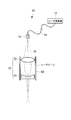
- the condensing lens 22 and the concave lens 24 are described as different lenses.
- these lenses are an integrated lens group 60, and the lens group 60 has a different curvature.
- the position of inversion may be adjusted by exchanging with the group lens 60.
- the laser cutting device 10 inverts the laser beam using the spherical aberration of the spherical lens and focuses the laser beam in a circular shape, so that the workpiece can be processed with a simple configuration.
- the laser beam can be generated by reversing the inside and outside, and the machining direction is not limited in machining the workpiece.
- the present invention is not limited to this, and as a form using other gas such as nitrogen gas or argon gas as the assist gas. Also good.
- a fiber laser is used for the laser cutting device 10 .
- the present invention is not limited to this.
- a disk laser (wavelength 1.05) transmitted by an optical fiber is used. ⁇ 1.09 ⁇ m), YAG laser, gas laser CO 2 laser, or other lasers may be used.
- the intensity distribution of the laser beam is made to be a caldera using a spherical lens.
- the present invention is not limited to this, and sufficient aberration correction is not performed (
- the intensity distribution of the laser beam may be in the form of a caldera using an aspheric lens capable of generating spherical aberration.
- the intensity distribution of the laser beam may be a caldera shape by combining the spherical lens and the aspheric lens.
Landscapes
- Physics & Mathematics (AREA)
- Optics & Photonics (AREA)
- Engineering & Computer Science (AREA)
- Plasma & Fusion (AREA)
- Mechanical Engineering (AREA)
- General Physics & Mathematics (AREA)
- Laser Beam Processing (AREA)
Priority Applications (4)
| Application Number | Priority Date | Filing Date | Title |
|---|---|---|---|
| JP2013517726A JP5602300B2 (ja) | 2011-05-30 | 2011-05-30 | レーザ加工ヘッド、レーザ加工装置、レーザ加工装置の光学系、レーザ加工方法、及びレーザ集束方法 |
| PCT/JP2011/062391 WO2012164663A1 (ja) | 2011-05-30 | 2011-05-30 | レーザ加工ヘッド、レーザ加工装置、レーザ加工装置の光学系、レーザ加工方法、及びレーザ集束方法 |
| US13/982,790 US9346126B2 (en) | 2011-05-30 | 2011-05-30 | Laser processing head, laser processing apparatus, optical system of laser processing apparatus, laser processing method, and laser focusing method |
| EP11866675.9A EP2716397B1 (de) | 2011-05-30 | 2011-05-30 | Optisches system für eine laserbearbeitungsvorrichtung, laserbearbeitungskopf mit einem solchen system, laserbearbeitungsvorrichtung mit einem solchen kopf, laserbearbeitungsverfahren, und laserfokussierungsverfahren unter verwendung eines solchen verfahren |
Applications Claiming Priority (1)
| Application Number | Priority Date | Filing Date | Title |
|---|---|---|---|
| PCT/JP2011/062391 WO2012164663A1 (ja) | 2011-05-30 | 2011-05-30 | レーザ加工ヘッド、レーザ加工装置、レーザ加工装置の光学系、レーザ加工方法、及びレーザ集束方法 |
Publications (1)
| Publication Number | Publication Date |
|---|---|
| WO2012164663A1 true WO2012164663A1 (ja) | 2012-12-06 |
Family
ID=47258549
Family Applications (1)
| Application Number | Title | Priority Date | Filing Date |
|---|---|---|---|
| PCT/JP2011/062391 Ceased WO2012164663A1 (ja) | 2011-05-30 | 2011-05-30 | レーザ加工ヘッド、レーザ加工装置、レーザ加工装置の光学系、レーザ加工方法、及びレーザ集束方法 |
Country Status (4)
| Country | Link |
|---|---|
| US (1) | US9346126B2 (de) |
| EP (1) | EP2716397B1 (de) |
| JP (1) | JP5602300B2 (de) |
| WO (1) | WO2012164663A1 (de) |
Cited By (7)
| Publication number | Priority date | Publication date | Assignee | Title |
|---|---|---|---|---|
| JP2015115231A (ja) * | 2013-12-12 | 2015-06-22 | アズビル株式会社 | 紫外線放電管の製造方法 |
| CN105458493A (zh) * | 2014-09-30 | 2016-04-06 | 发那科株式会社 | 激光加工装置 |
| JP2017001097A (ja) * | 2016-08-03 | 2017-01-05 | 株式会社アマダホールディングス | レーザ加工機 |
| JP2022063975A (ja) * | 2020-10-13 | 2022-04-25 | 株式会社タムロン | レーザビーム照射用光学ユニット及びレーザ加工装置 |
| JPWO2023286265A1 (de) * | 2021-07-16 | 2023-01-19 | ||
| CN117001173A (zh) * | 2023-09-12 | 2023-11-07 | 重庆奥方工贸有限公司 | 一种汽车车灯透镜激光切割装置 |
| DE102024104564A1 (de) | 2023-03-10 | 2024-09-12 | Tamron Co., Ltd. | Optisches system einer laserbearbeitungsvorrichtung und laserbearbeitungsvorrichtung |
Families Citing this family (14)
| Publication number | Priority date | Publication date | Assignee | Title |
|---|---|---|---|---|
| TWI772353B (zh) * | 2017-01-16 | 2022-08-01 | 日商索尼股份有限公司 | 光偵測方法、光偵測裝置及程式產品 |
| EP3412400A1 (de) | 2017-06-09 | 2018-12-12 | Bystronic Laser AG | Strahlformer und verwendung davon, vorrichtung zur laserstrahlbehandlung eines werkstücks und verwendung davon, verfahren zur laserstrahlbehandlung eines werkstücks |
| DE112018004574T5 (de) * | 2017-10-17 | 2020-06-25 | Mitsubishi Electric Corporation | Laserbearbeitungsmaschine |
| US11597033B2 (en) * | 2018-03-23 | 2023-03-07 | Primetals Technologies Japan, Ltd. | Laser processing head, laser processing device, and method for adjusting laser processing head |
| CN108941896B (zh) * | 2018-07-06 | 2021-04-16 | 武汉光谷航天三江激光产业技术研究院有限公司 | 激光聚焦装置及激光系统 |
| DE102019115554A1 (de) * | 2019-06-07 | 2020-12-10 | Bystronic Laser Ag | Bearbeitungsvorrichtung zur Laserbearbeitung eines Werkstücks und Verfahren zur Laserbearbeitung eines Werkstücks |
| DE102019122064A1 (de) | 2019-08-16 | 2021-02-18 | Bystronic Laser Ag | Bearbeitungsvorrichtung zur Laserbearbeitung eines Werkstücks, Teilesatz für eine Bearbeitungsvorrichtung zur Laserbearbeitung eines Werkstücks und Verfahren zur Laserbearbeitung eines Werkstücks |
| US12265207B2 (en) * | 2021-03-04 | 2025-04-01 | Ii-Vi Delaware, Inc. | Dynamic focus for laser processing head |
| EP4056309A1 (de) | 2021-03-09 | 2022-09-14 | Bystronic Laser AG | Vorrichtung und verfahren zum laserschneiden eines werkstücks und erzeugen von werkstückteilen |
| KR102696979B1 (ko) * | 2021-08-23 | 2024-08-20 | 주식회사 대곤코퍼레이션 | 레이저가공장치 및 이를 이용해 객체를 가공하는 방법 |
| NL2030028B1 (en) * | 2021-12-03 | 2023-06-20 | Inphocal B V | Laser marking system |
| EP4477346A1 (de) | 2023-06-14 | 2024-12-18 | Bystronic Laser AG | Laserbearbeitungsvorrichtung zum bearbeiten eines werkstücks, verwendung derselben, verfahren zum laserbearbeiten eines werkstücks |
| NL2035705B1 (en) | 2023-08-30 | 2025-03-11 | Inphocal B V | Laser cutting system |
| CN120480383B (zh) * | 2025-07-08 | 2025-10-03 | 西安晟光硅研半导体科技有限公司 | 一种用于微射流激光加工头的非球面物镜 |
Citations (3)
| Publication number | Priority date | Publication date | Assignee | Title |
|---|---|---|---|---|
| JP2003305581A (ja) * | 2002-04-11 | 2003-10-28 | Toyota Motor Corp | レーザ溶接方法およびレーザ溶接装置 |
| JP2008139476A (ja) | 2006-11-30 | 2008-06-19 | Sumitomo Electric Ind Ltd | 集光光学系及びレーザ加工装置 |
| JP2009208092A (ja) * | 2008-02-29 | 2009-09-17 | Toyota Motor Corp | レーザ加工装置及びレーザ加工方法 |
Family Cites Families (18)
| Publication number | Priority date | Publication date | Assignee | Title |
|---|---|---|---|---|
| US5352495A (en) * | 1989-02-16 | 1994-10-04 | The Wiggins Teape Group Limited | Treatment of a surface by laser energy |
| JP2880061B2 (ja) * | 1994-02-03 | 1999-04-05 | 住友重機械工業株式会社 | レーザ加工 |
| JPH09108879A (ja) * | 1995-10-20 | 1997-04-28 | Hitachi Constr Mach Co Ltd | レーザ加工装置 |
| WO1997016387A1 (en) * | 1995-11-03 | 1997-05-09 | Anatoly Valentinovich Vasilev | Laser-based method of forming an image in transparent objects |
| JPH11254160A (ja) * | 1998-03-10 | 1999-09-21 | Matsushita Electric Ind Co Ltd | レーザ装置 |
| JP3287318B2 (ja) | 1998-10-13 | 2002-06-04 | 松下電器産業株式会社 | 光ビーム加熱装置 |
| JP2003236690A (ja) * | 2002-02-14 | 2003-08-26 | Sumitomo Heavy Ind Ltd | レーザ加工方法 |
| US6884962B2 (en) * | 2002-03-18 | 2005-04-26 | Hitachi Via Mechanics, Ltd. | Beam or wave front |
| JP4350558B2 (ja) | 2004-03-09 | 2009-10-21 | 三菱電機株式会社 | レーザビーム光学系およびレーザ加工装置 |
| JP2006035303A (ja) * | 2004-07-30 | 2006-02-09 | Tdk Corp | レーザ加工方法及びレーザ加工装置 |
| JP2007029990A (ja) * | 2005-07-26 | 2007-02-08 | Sumitomo Heavy Ind Ltd | レーザ加工装置およびレーザ加工方法 |
| US7626138B2 (en) * | 2005-09-08 | 2009-12-01 | Imra America, Inc. | Transparent material processing with an ultrashort pulse laser |
| US7656592B2 (en) * | 2005-12-16 | 2010-02-02 | Reliant Technologies, Inc. | Optical system having aberrations for transforming a Gaussian laser-beam intensity profile to a quasi-flat-topped intensity profile in a focal region of the optical system |
| US9211609B2 (en) * | 2005-12-28 | 2015-12-15 | Intel Corporation | Laser via drilling apparatus and methods |
| US7847213B1 (en) * | 2007-09-11 | 2010-12-07 | Ultratech, Inc. | Method and apparatus for modifying an intensity profile of a coherent photonic beam |
| US8288682B2 (en) * | 2007-09-28 | 2012-10-16 | Intel Corporation | Forming micro-vias using a two stage laser drilling process |
| JP5190421B2 (ja) | 2009-08-03 | 2013-04-24 | 株式会社アマダ | 小型熱レンズ補償加工ヘッド |
| JP5832412B2 (ja) * | 2012-11-12 | 2015-12-16 | 三菱重工業株式会社 | 光学系及びレーザ加工装置 |
-
2011
- 2011-05-30 WO PCT/JP2011/062391 patent/WO2012164663A1/ja not_active Ceased
- 2011-05-30 EP EP11866675.9A patent/EP2716397B1/de active Active
- 2011-05-30 JP JP2013517726A patent/JP5602300B2/ja active Active
- 2011-05-30 US US13/982,790 patent/US9346126B2/en active Active
Patent Citations (3)
| Publication number | Priority date | Publication date | Assignee | Title |
|---|---|---|---|---|
| JP2003305581A (ja) * | 2002-04-11 | 2003-10-28 | Toyota Motor Corp | レーザ溶接方法およびレーザ溶接装置 |
| JP2008139476A (ja) | 2006-11-30 | 2008-06-19 | Sumitomo Electric Ind Ltd | 集光光学系及びレーザ加工装置 |
| JP2009208092A (ja) * | 2008-02-29 | 2009-09-17 | Toyota Motor Corp | レーザ加工装置及びレーザ加工方法 |
Non-Patent Citations (1)
| Title |
|---|
| See also references of EP2716397A4 * |
Cited By (14)
| Publication number | Priority date | Publication date | Assignee | Title |
|---|---|---|---|---|
| JP2015115231A (ja) * | 2013-12-12 | 2015-06-22 | アズビル株式会社 | 紫外線放電管の製造方法 |
| CN105458493A (zh) * | 2014-09-30 | 2016-04-06 | 发那科株式会社 | 激光加工装置 |
| JP2016068131A (ja) * | 2014-09-30 | 2016-05-09 | ファナック株式会社 | 集光径を拡大できるレーザ加工装置 |
| US9656349B2 (en) | 2014-09-30 | 2017-05-23 | Fanuc Corporation | Laser processing apparatus capable of increasing focused beam diameter |
| CN105458493B (zh) * | 2014-09-30 | 2017-10-27 | 发那科株式会社 | 激光加工装置 |
| JP2017001097A (ja) * | 2016-08-03 | 2017-01-05 | 株式会社アマダホールディングス | レーザ加工機 |
| JP2022063975A (ja) * | 2020-10-13 | 2022-04-25 | 株式会社タムロン | レーザビーム照射用光学ユニット及びレーザ加工装置 |
| JP7706877B2 (ja) | 2020-10-13 | 2025-07-14 | 株式会社タムロン | レーザビーム照射用光学ユニット及びレーザ加工装置 |
| JPWO2023286265A1 (de) * | 2021-07-16 | 2023-01-19 | ||
| WO2023286265A1 (ja) * | 2021-07-16 | 2023-01-19 | 三菱電機株式会社 | レーザ加工装置及びレーザ加工方法 |
| JP7584658B2 (ja) | 2021-07-16 | 2024-11-15 | 三菱電機株式会社 | レーザ加工装置及びレーザ加工方法 |
| DE102024104564A1 (de) | 2023-03-10 | 2024-09-12 | Tamron Co., Ltd. | Optisches system einer laserbearbeitungsvorrichtung und laserbearbeitungsvorrichtung |
| CN117001173A (zh) * | 2023-09-12 | 2023-11-07 | 重庆奥方工贸有限公司 | 一种汽车车灯透镜激光切割装置 |
| CN117001173B (zh) * | 2023-09-12 | 2024-05-07 | 重庆奥方工贸有限公司 | 一种汽车车灯透镜激光切割装置 |
Also Published As
| Publication number | Publication date |
|---|---|
| EP2716397A4 (de) | 2015-03-11 |
| EP2716397A1 (de) | 2014-04-09 |
| US20130306609A1 (en) | 2013-11-21 |
| EP2716397B1 (de) | 2016-07-20 |
| JP5602300B2 (ja) | 2014-10-08 |
| US9346126B2 (en) | 2016-05-24 |
| JPWO2012164663A1 (ja) | 2014-07-31 |
Similar Documents
| Publication | Publication Date | Title |
|---|---|---|
| JP5602300B2 (ja) | レーザ加工ヘッド、レーザ加工装置、レーザ加工装置の光学系、レーザ加工方法、及びレーザ集束方法 | |
| JP5832412B2 (ja) | 光学系及びレーザ加工装置 | |
| JP5033693B2 (ja) | ファイバレーザ加工機における集光直径の変換制御方法及びその装置 | |
| WO2008069099A1 (ja) | 集光光学系、レーザ加工方法及び装置、並びに脆性材料素材の製造方法 | |
| KR101346296B1 (ko) | 레이저 가공 장치 및 방법 | |
| JP2720811B2 (ja) | レーザ集光方法及び装置 | |
| JP2009178725A (ja) | レーザ加工装置及びレーザ加工方法 | |
| JP2007310368A (ja) | ホモジナイザを用いた整形ビームの伝搬方法およびそれを用いたレ−ザ加工光学系 | |
| JP2005028428A (ja) | レーザ加工装置 | |
| CN110908099A (zh) | 一种用于激光焊接机的准远心高功率光学聚焦镜头及其成像方法 | |
| WO2021184519A1 (zh) | 一种激光装置 | |
| CN114160965A (zh) | 激光成丝切割装置 | |
| JP2015044225A (ja) | レーザ加工装置 | |
| JP5595573B1 (ja) | レーザ加工装置及びレーザ加工方法 | |
| JP6920540B2 (ja) | レーザ加工ヘッド及びレーザ加工装置並びにレーザ加工ヘッドの調整方法 | |
| JP2006150433A (ja) | レーザ加工装置 | |
| JP5221031B2 (ja) | 集光光学系及びレーザ加工装置 | |
| CN113325590A (zh) | 扫描式光源模块 | |
| JP5943812B2 (ja) | レーザ切断装置及びレーザ切断方法 | |
| JP7780862B2 (ja) | レーザ加工装置、レーザ加工装置の光学系 | |
| CN223526590U (zh) | 光束整形模组、激光光源系统、激光切割和激光焊接装置 | |
| CN118577932B (zh) | 一种三片式带衍射环的贝塞尔光束整形系统 | |
| JP2003290961A (ja) | レーザ加工装置 | |
| CN118616880A (zh) | 激光加工装置的光学系统及激光加工装置 | |
| CN116900473A (zh) | 金属零件的制造方法 |
Legal Events
| Date | Code | Title | Description |
|---|---|---|---|
| 121 | Ep: the epo has been informed by wipo that ep was designated in this application |
Ref document number: 11866675 Country of ref document: EP Kind code of ref document: A1 |
|
| ENP | Entry into the national phase |
Ref document number: 2013517726 Country of ref document: JP Kind code of ref document: A |
|
| REEP | Request for entry into the european phase |
Ref document number: 2011866675 Country of ref document: EP |
|
| WWE | Wipo information: entry into national phase |
Ref document number: 13982790 Country of ref document: US Ref document number: 2011866675 Country of ref document: EP |
|
| NENP | Non-entry into the national phase |
Ref country code: DE |