WO2012164839A1 - レーザ接合部品およびその製造方法 - Google Patents
レーザ接合部品およびその製造方法 Download PDFInfo
- Publication number
- WO2012164839A1 WO2012164839A1 PCT/JP2012/003158 JP2012003158W WO2012164839A1 WO 2012164839 A1 WO2012164839 A1 WO 2012164839A1 JP 2012003158 W JP2012003158 W JP 2012003158W WO 2012164839 A1 WO2012164839 A1 WO 2012164839A1
- Authority
- WO
- WIPO (PCT)
- Prior art keywords
- metal plate
- laser
- metal
- joined
- component according
- Prior art date
- Legal status (The legal status is an assumption and is not a legal conclusion. Google has not performed a legal analysis and makes no representation as to the accuracy of the status listed.)
- Ceased
Links
Images





Classifications
-
- B—PERFORMING OPERATIONS; TRANSPORTING
- B23—MACHINE TOOLS; METAL-WORKING NOT OTHERWISE PROVIDED FOR
- B23K—SOLDERING OR UNSOLDERING; WELDING; CLADDING OR PLATING BY SOLDERING OR WELDING; CUTTING BY APPLYING HEAT LOCALLY, e.g. FLAME CUTTING; WORKING BY LASER BEAM
- B23K26/00—Working by laser beam, e.g. welding, cutting or boring
- B23K26/08—Devices involving relative movement between laser beam and workpiece
- B23K26/083—Devices involving movement of the workpiece in at least one axial direction
- B23K26/0853—Devices involving movement of the workpiece in at least two axial directions, e.g. in a plane
-
- B—PERFORMING OPERATIONS; TRANSPORTING
- B23—MACHINE TOOLS; METAL-WORKING NOT OTHERWISE PROVIDED FOR
- B23K—SOLDERING OR UNSOLDERING; WELDING; CLADDING OR PLATING BY SOLDERING OR WELDING; CUTTING BY APPLYING HEAT LOCALLY, e.g. FLAME CUTTING; WORKING BY LASER BEAM
- B23K26/00—Working by laser beam, e.g. welding, cutting or boring
- B23K26/20—Bonding
- B23K26/21—Bonding by welding
- B23K26/211—Bonding by welding with interposition of special material to facilitate connection of the parts
-
- B—PERFORMING OPERATIONS; TRANSPORTING
- B23—MACHINE TOOLS; METAL-WORKING NOT OTHERWISE PROVIDED FOR
- B23K—SOLDERING OR UNSOLDERING; WELDING; CLADDING OR PLATING BY SOLDERING OR WELDING; CUTTING BY APPLYING HEAT LOCALLY, e.g. FLAME CUTTING; WORKING BY LASER BEAM
- B23K26/00—Working by laser beam, e.g. welding, cutting or boring
- B23K26/20—Bonding
- B23K26/21—Bonding by welding
- B23K26/24—Seam welding
- B23K26/244—Overlap seam welding
-
- B—PERFORMING OPERATIONS; TRANSPORTING
- B23—MACHINE TOOLS; METAL-WORKING NOT OTHERWISE PROVIDED FOR
- B23K—SOLDERING OR UNSOLDERING; WELDING; CLADDING OR PLATING BY SOLDERING OR WELDING; CUTTING BY APPLYING HEAT LOCALLY, e.g. FLAME CUTTING; WORKING BY LASER BEAM
- B23K26/00—Working by laser beam, e.g. welding, cutting or boring
- B23K26/20—Bonding
- B23K26/32—Bonding taking account of the properties of the material involved
- B23K26/323—Bonding taking account of the properties of the material involved involving parts made of dissimilar metallic material
-
- B—PERFORMING OPERATIONS; TRANSPORTING
- B23—MACHINE TOOLS; METAL-WORKING NOT OTHERWISE PROVIDED FOR
- B23K—SOLDERING OR UNSOLDERING; WELDING; CLADDING OR PLATING BY SOLDERING OR WELDING; CUTTING BY APPLYING HEAT LOCALLY, e.g. FLAME CUTTING; WORKING BY LASER BEAM
- B23K2103/00—Materials to be soldered, welded or cut
- B23K2103/18—Dissimilar materials
- B23K2103/20—Ferrous alloys and aluminium or alloys thereof
Definitions
- the present invention relates to a laser-joined component including dissimilar metal plates having different melting points and a method for manufacturing the same.
- the conventional laser joining parts for dissimilar metal plates and the manufacturing method thereof are as follows: a low melting point material is superimposed on the bottom surface of a high melting point material, and laser light is output when the top surface of the high melting point material is irradiated with laser light. There is a value in which a melt of a material having a high melting point is dissolved in a wedge shape to an appropriate depth of a material having a low melting point (see, for example, Patent Document 1).
- FIG. 14 is a cross-sectional view of a joining portion showing a conventional laser joining component described in Patent Document 1 and a manufacturing method thereof. In FIG.
- the laser beam is irradiated to the material 1 side having a high melting point, and the melt 3 of this material breaks the intermetallic compound and is melted into the wedge-shaped region 4 having an appropriate depth up to the inside of the material 2 having a low melting point. .
- FIG. 15 is a conceptual diagram showing a conventional laser-joined component described in Patent Document 2 and a manufacturing method thereof.
- the iron-based material is caused by the difference in melting points.
- the aluminum-based metal melts to a certain depth while the surface of the metal melts.
- the molten aluminum-based metal 9 flows out by gravity and flows so as to cover a part or all of the surface of the molten iron-based metal (the flange portion 7a of the battery lid 7).
- the fluidized aluminum-based metal and the molten iron-based metal in contact therewith are fused.
- the above-described conventional technique has a problem that necessary joining cannot be performed in the case of a product structure that can be heated and melted only from the side of the metal plate having a low melting point such as laser irradiation.
- first and second dissimilar metal plates having different melting points are overlapped, and laser irradiation is performed from the upper surface side of the second metal plate having a relatively low melting point.
- a technique for providing a plurality of spot-like welds is disclosed.
- the thermal effect on the lower surface side of the first metal plate having a relatively high melting point has not been considered. Therefore, use has been restricted depending on the member disposed on the lower surface side of the first metal plate.
- problems remain in the bonding strength of the first and second dissimilar metal plates.
- the present invention solves the above-described conventional problems, and provides a laser-joined component and a method of manufacturing the same that enable joining from a metal side having a low melting point in lap joining of dissimilar metal plates having different melting points. With the goal.
- Another object of the present invention is to provide a laser-joined component capable of suppressing a temperature rise on the lower surface side of a metal having a high melting point and a method for manufacturing the same. The object is to improve the bonding strength between different kinds of metal plates.
- the laser-joined component and the manufacturing method thereof of the present invention it is possible to perform joining from the metal side having a low melting point in the lap joining of dissimilar metal plates having different melting points. Temperature rise can be suppressed. The joint strength between dissimilar metal plates can be improved.
- FIG. 1A is a top view of the laser-joined component according to Embodiment 1.
- FIG. 1B is a cross-sectional view of the laser bonded component according to Embodiment 1.
- FIG. 2 is a conceptual diagram of the configuration of the laser joining component and the manufacturing apparatus used in the manufacturing method according to the first embodiment.
- FIG. 3A is a schematic diagram of a cross-section of a joining step in the method for manufacturing a laser-joined component according to Embodiment 1.
- FIG. 3B is a schematic diagram of a cross-section of a joining step in the method for manufacturing a laser-joined component in Embodiment 1.
- FIG. 4 is a cross-sectional photograph of the vicinity of the joining portion of the laser joining component obtained in the example of the first embodiment.
- FIG. 5 is a schematic diagram of the vicinity of the joint portion of the laser joining component obtained in the example of the first embodiment.
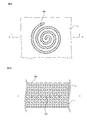
- FIG. 6A is a top view of a laser bonded component according to a modification of the first embodiment.
- FIG. 6B is a cross-sectional view of a laser bonded component according to a modification of the first embodiment.
- FIG. 7A is a schematic cross-sectional view of a joining step in the method for manufacturing a laser-joined component according to the modification of the first embodiment.
- FIG. 7B is a schematic cross-sectional view of a joining step in the method for manufacturing a laser-joined component according to the modification of the first embodiment.
- FIG. 6A is a top view of a laser bonded component according to a modification of the first embodiment.
- FIG. 6B is a cross-sectional view of a laser bonded component according to a modification of the first embodiment.
- FIG. 7A is a schematic cross-sectional view of a joining step in the method
- FIG. 8 is a conceptual diagram of the steps (manufacturing apparatus) of the laser-joined component and the manufacturing method thereof according to the second embodiment.
- FIG. 9A is a schematic diagram of a cross-section of a joining step in the method for manufacturing a laser-joined component in Embodiment 2.
- FIG. 9B is a schematic diagram of a cross-section of a joining step in the method for manufacturing a laser-joined component in Embodiment 2.
- FIG. 10 is a cross-sectional photograph of the vicinity of the joining portion of the laser joining component in the second embodiment.
- FIG. 11 is a cross-sectional photograph of the vicinity of the joining portion of the laser joining component in the second embodiment.
- FIG. 12 is a photograph showing melting marks formed on the upper surface of the second metal plate of the laser joining component as a reference example.
- FIG. 13 is a cross-sectional photograph of a joined portion of a laser joining component as a reference example.
- FIG. 14 is a cross-sectional view of a joining portion showing a conventional laser joining component described in Patent Document 1 and a manufacturing method thereof.
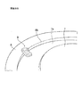
- FIG. 15 is a surface view showing a conventional laser-joined component described in Patent Document 2 and a manufacturing method thereof.
- FIG. 1A is a top view of the laser-joined component according to Embodiment 1.
- FIG. 1B is a cross-sectional view of the laser bonded component according to Embodiment 1.
- the laser-joined component according to Embodiment 1 includes a first metal plate 11 formed of steel and a first metal plate 11 that is laser-joined on the first metal plate 11.
- a second metal plate 12 made of aluminum having a lower melting point.
- a melt mark 26 is formed on the upper surface 12 a of the second metal plate 12.
- the melt mark 26 is preferably formed in a curved shape so that the line does not have a tolerance. This is because sufficient bonding strength is easily obtained in a narrow bonding area between the first metal plate 11 and the second metal plate 12. Specifically, it is preferably formed in a circular shape as shown in FIG. 1A. This is because, by forming the melt mark 26 in a circular shape, the bonding strength is increased by applying an isotropic force to the bonded portion from the outside. According to the first embodiment, it is possible to increase the bonding strength between different metal plates.
- a wedge-like shape is formed from the second metal plate side 12 toward the inside from the upper surface 11a of the first metal plate 11.
- Region 25 is formed.
- the depth of the wedge-shaped region 25 from the upper surface of the first metal plate 11 is preferably 75% or less of the plate thickness of the first metal plate 11. This is to eliminate the thermal effect on the lower surface side of the first metal plate 11. No thermal history (effect of heat) is observed on the lower surface 11b of the first metal plate 11. Therefore, various dissimilar metal plates can be joined without being limited by the characteristics of the members disposed on the lower surface side of the first metal plate 11.
- the thickness of the second metal plate 12 is not particularly limited as long as the rigidity as the structure can be secured, but is preferably 0.1 mm or more and 2.0 mm or less. This is because if the thickness of the second metal plate 12 is less than 0.1 mm, it is difficult to ensure the rigidity of the structure.
- the thickness of the second metal plate 12 exceeds 2.0 mm, when the molten aluminum 24 reaches the boundary with the first metal plate 11, the surface temperature on the laser light irradiation side reaches the boiling point due to the temperature gradient. This is because the removal process proceeds due to the rapid evaporation of aluminum and the plate thickness becomes thin.
- the mixed layer in which at least one of the metal of the first metal plate 11 or the metal layer is included in the metal of the second metal plate 12. Further, in the vicinity of the joint interface in the wedge-shaped region, there is a mixed layer in which at least one of the metal of the second metal plate 12 or the metal layer is included in the metal of the first metal plate 11.
- the mixed layer is preferably a non-equilibrium phase.
- FIG. 2 is a configuration diagram of a manufacturing apparatus used in the laser-joined component and the manufacturing method thereof according to Embodiment 1 of the present invention.
- the manufacturing apparatus includes a Y-axis table 16, an X-axis table 15 connected on the Y-axis table 16, and a fixed plate 14 fixed on the X-axis table 15.
- a first metal plate (steel plate) 11 and a second metal plate (aluminum plate) 12 can be arranged.
- the first metal plate 11 and the second metal plate 12 can be fixed on the fixing plate 14 by the fixing metal 13.
- the manufacturing apparatus further includes a controller 21, a YAG laser oscillator 17, a reflecting mirror 19, and a condenser lens 20.
- the controller 21 is connected to the X-axis table 15 and the Y-axis table 16 via a signal line 22.
- the controller 21 is connected to the YAG laser oscillator 17 via the signal line 23.
- the laser beam 18 emitted from the YAG laser oscillator 17 is emitted.
- the laser beam 18 emitted from the YAG laser oscillator 17 is bent 90 degrees by the reflecting mirror 19, passes through the condenser lens 20, and is then applied to the second metal plate 12. Thereby, the 1st metal plate 11 and the 2nd metal plate 12 are joined.
- the apparatus of the X and Y axis table movement system was demonstrated as a manufacturing apparatus. However, if the relative position between the laser light source and the second metal plate 12 can be moved and the laser light 18 can be scanned onto the second metal plate 12, another type of manufacturing apparatus can be used. You may use. For example, it may be an optical moving manufacturing apparatus, or a combined manufacturing apparatus of the X and Y axis table moving system and the optical moving system.
- controller 21 is not shown in the drawing, (b) calculation control unit, (b) physical property information of the first metal plate 11 and the second metal plate 12, laser irradiation conditions and irradiation patterns.
- Information, for example, lot numbers, physical property information of the first and second metal plates 11, 12, laser irradiation conditions, and irradiation patterns are stored in association with each other. And a storage device for storing information on whether 25 is formed.
- the arithmetic control unit may be configured by an arithmetic device used in a normal computer system such as a CPU.
- Examples of the input device include pointing devices such as a keyboard and a mouse.
- Examples of the output device include a printer.
- Examples of the display device include an image display device such as a liquid crystal display and a monitor.
- a storage device such as a ROM, a RAM, or a magnetic disk can be used.
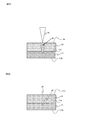
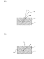
- FIG. 3A is a schematic view of a cross section during laser irradiation in the bonding process.
- FIG. 3B is a schematic view of the solidified state after the laser irradiation in the joining process. A method for manufacturing a laser-joined component will be described with reference to FIGS. 3A and 3B.
- a manufacturing apparatus as shown in FIG. 2 is prepared.
- a first metal plate (steel plate) 11 made of steel and a second metal plate (aluminum plate) 12 made of aluminum having a melting point lower than that of the first metal plate 11 are prepared.
- the first metal plate 11 is disposed on the fixed plate 14, and the second metal plate 12 is disposed on the first metal plate 11.
- the first metal plate 11 and the second metal plate 12 are fixed on the fixing plate 14 by the fixing metal 13.
- the physical property information of the first metal plate 11 and the second metal plate 12, the laser irradiation conditions and the irradiation pattern are input to the controller 21.
- the laser irradiation condition or the like may be set by calling a desired laser irradiation condition or the like from the storage device.
- a laser is scanned on the second metal plate 12 while forming a melt mark 26 on the upper surface 12 a of the second metal plate 12.
- a signal is sent from the controller 21 to the X-axis table 15 and the Y-axis table 16 to adjust the position of the second metal plate 12, while the second metal plate 12 is adjusted in the same manner as in the step (c).
- Laser irradiation is performed. It is preferable to adjust the position of the second metal plate 12 so that the melt mark 26 is irradiated with a laser beam in a curved shape so as not to have tolerance.
- melt mark 26 is circular. This is because the time to return to the irradiation start point can be omitted as compared with the case of irradiation with a straight line. Further, the laser irradiation is continued while adjusting the output of the laser irradiated from the YAG laser oscillator 17 by the controller 21 as appropriate.
- the first metal plate 11 is connected from the second metal plate side 12 at the bonding interface between the first metal plate 11 and the second metal plate 12.
- a wedge-shaped region 25 is formed inward. That is, when the molten aluminum 24 is solidified, a wedge-shaped region 25 remains in the first metal plate 11. Further, a melt mark 26 is formed on the upper surface of the second metal plate 12 due to the influence of heat by laser irradiation.
- the second metal plate 12 is laser-bonded on the first metal plate 11 as described above.
- a laser-joined component can be manufactured without leaving a thermal history (influence of heat) on the lower surface 11 b of the first metal plate 11.
- dissimilar metal plates can be bonded with strong bonding strength without being restricted by a member disposed on the lower surface 11b side of the first metal plate 11. Examples of applications that make use of the characteristics of the first embodiment include laser-joined parts obtained by joining an aluminum electrode and a battery, which will be described later as a second embodiment.
- a laser bonded component was manufactured under the following conditions.
- carbon steel having a plate thickness of 0.3 mm and a carbon content of 0.3% was used.
- aluminum (Al) plate having a plate thickness of 0.4 mm and a purity of 99.5% was used.
- the laser verification conditions were a laser output of 200 W, an irradiation spot diameter of 0.15 mm, and a scanning speed of 30 mm / second.
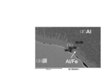
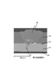
- FIG. 4 is a cross-sectional photograph of the vicinity of the bonded portion of the laser bonded component obtained in the example.
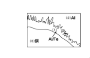
- FIG. 4 shows a portion corresponding to the boundary portion of the wedge-shaped region 25 shown in FIG. 3B.
- FIG. 5 is a schematic diagram of a cross-sectional photograph of the vicinity of the joint portion of the laser-joined component and the manufacturing method thereof in the embodiment.
- the melting mark is formed in a circular shape.
- the shape of the melt mark is not limited to a circular shape, and may be another curved shape.
- a spiral (spiral) melting mark 26b may be formed.
- the melt mark 26 may be formed in a wave shape.
- laser irradiation was performed perpendicularly to the upper surface of the second metal plate 12 in the laser bonding step.
- a wedge-shaped region was formed in the vertical direction from the upper surface to the lower surface of the first metal plate.
- FIG. 1 As shown in FIG.
- the upper surface of the second metal plate 12 may be irradiated with laser from an oblique direction to form a molten aluminum 24a region. That is, as shown in FIG. 7B, the wedge-shaped region 25 a may be formed obliquely with respect to the upper surface 11 a of the first metal plate 11.
- the first metal plate 11 was not provided with a metal layer.
- a metal layer may be provided on at least one surface of the first metal plate. This is because, for example, by providing a nickel plating layer as the metal layer, the adhesive strength is improved. This is thought to be due to the fact that nickel is added to the melted portion, so that the composition ratio of low-strength aluminum is relatively lowered, so that the bonding strength is increased.
- the metal layer is preferably provided on the joint surface side with the second metal plate 12. As the metal layer, nickel, zinc, or tin can be used.
- FIG. 8 is a conceptual diagram of the steps (manufacturing apparatus) of the laser-joined component and the manufacturing method thereof in the second embodiment.
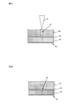
- FIG. 9A and FIG. 9B are schematic views of cross sections of a joining process in the method for manufacturing a laser joined component in the second embodiment.
- the laser bonding component includes a battery 31 and an aluminum electrode 32 bonded (arranged) on the bottom surface 31 a of the battery 31.
- the outer case of the battery 31 a case in which nickel plating layers 35 and 36 are provided on the surface of a steel plate 34 having a thickness of 0.3 mm as shown in FIG. 9A can be used.
- the thickness of the nickel plating layer 35 on the surface can be 3 ⁇ m, and the thickness of the nickel plating layer 36 on the bottom surface can be 0.3 ⁇ m.
- the aluminum electrode 32 one having a plate thickness of 0.4 mm can be used.
- FIGS. 9A and 9B A method for manufacturing a laser-joined component will be described with reference to FIGS. 9A and 9B.
- A First, a battery 31 and an aluminum electrode 32 are prepared.
- the battery 31 is arranged with the bottom surface 31a facing up.
- C The aluminum electrode 32 is disposed on the bottom surface 31 a of the battery 31, and the aluminum electrode 32 is pressed by the fixing jig 33.
- D In the same manner as in the first embodiment, the laser light 18 is irradiated onto the aluminum electrode 32 and simultaneously the laser light 18 is scanned. Then, as shown in FIG.
- the melted portion (molten aluminum 37) develops in the depth direction from the place where the laser beam 18 is irradiated, and reaches the nickel plating layer 35 on the surface of the steel plate 34.
- the nickel plating layer 35 does not melt at the melting temperature of aluminum, but if the laser irradiation heat energy is sufficient, the nickel plating layer 35 at the interface melts and part of the surface of the steel plate 34 also melts.
- the component elements of the nickel plating layer 35 and the steel plate 34 that have melted at this time are mixed with aluminum in the molten aluminum 37.
- FIG. 9B when the laser irradiation is finished, the molten aluminum 37 penetrates the nickel plating layer 35 and a wedge-shaped region 38 remains in the steel plate 34.
- the aluminum electrode 32 is welded to the battery 31 as described above.
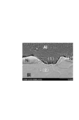
- FIG. 10 is a cross-sectional photograph of the vicinity of the joining portion of the laser joining component in the second embodiment. As shown in FIG. 10, it was confirmed that the wedge-shaped protrusion (1) bites into the steel plate side.
- the component ratio (atomic ratio) of the wedge-shaped protrusion (1) at the junction boundary was 92 for Al, 0 for Fe, and 8 for Ni. there were.
- the protrusion (1) is considered to be a layer in which only Al and Ni are mixed, but no Al—Ni intermetallic compound having a composition ratio corresponding to this was found.
- the component ratio (atomic ratio) of part (2) in FIG. 10 was 100 for Fe and 0 for Al and Ni. It is considered that Al is not mixed in the original steel.
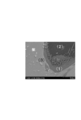
- FIG. 11 is a cross-sectional photograph of the vicinity of the joint taken at a location different from FIG. 10 in the same sample as FIG.
- the component ratio (atomic ratio) of the wedge-shaped protrusion (1) on the steel plate side was 70 for Al, 36 for Fe, and 1 for Ni.
- the component ratio (atomic ratio) of part (2) was 95 for Al, 4 for Fe, and 1 for Ni.
- the component ratio (atomic ratio) of part (3) was 14 for Al, 86 for Fe, and 0 for Ni.
- the protrusion (1) is close to FeAl 2 , but no other corresponding intermetallic compounds were found.
- Al can be dissolved in Fe up to 50 atm%. This general rule applies only to part (3).
- a mixed layer containing a metal having a high melting point or at least one of a surface metal and a metal having a low melting point exists in the wedge-shaped portion in the vicinity of the interface between the joints in FIGS. 10 and 11. .
- These mixed layers are considered to contain at least a non-equilibrium phase in addition to the intermetallic compound and the alloy phase. Even if these layers near the bonding interface are non-equilibrium phases, self-diffusion of each element hardly occurs in about 10 years in a use environment of 60 ° C. or less which is the high temperature side of the battery use condition range. There is almost no organizational change.
- FIG. 12 is a photograph showing melting marks formed on the upper surface of the second metal plate of the laser-joined component according to Reference Example 1. As shown in FIG. 12, laser irradiation was performed so that a circular melt mark 39 was formed on the aluminum electrode 32.
- Reference numeral 40 denotes an end point (start point) of laser irradiation. It has been found that the heat conduction in the depth direction in the steel plate 34 is reduced by the movement of the heating and melting portion, and as a result, the thermal influence on the nickel plating layer 36 on the back side is reduced.
- the reason why the laser is irradiated in a circular shape in Reference Example 1 is that the time to return to the irradiation start point can be omitted as compared with the case where irradiation is performed in a straight line. Further, it was found that the bonding strength was slightly increased by providing the nickel plating layer as compared with the case without the nickel plating layer. It is considered that the joining strength was slightly increased because nickel was added to the melted portion, so that the composition ratio of low-strength aluminum was relatively lowered.
- FIG. 13 is a cross-sectional photograph of a bonded portion of a laser bonded component manufactured as Reference Example 2. Under the conditions of Reference Example 2, thermal effects such as scorching and peeling of the nickel plating were observed on the lower surface of the nickel plating layer 36. The reason for this thermal effect is considered as follows.
- the wedge-shaped region 41 developed from the aluminum electrode 32 reached 78% of the plate thickness of the steel plate 34.
- the length of the wedge-shaped projections is preferably 75% or less of the steel plate in order to suppress the thermal influence on the lower surface.
- the constituent elements of the steel plate 34 and the nickel plating layer 35 existing in the wedge-shaped region 41 were mixed in the resolidified portion 42 of aluminum.
- the nickel plating layers 35 and 36 are provided on the front and back surfaces of the steel plate 34, but may be provided only on the bonding interface side.
- plating such as zinc or tin used for rust prevention of steel, or other elements may be used as the surface layer. This is because a non-equilibrium phase can be formed in the vicinity of the junction.
- zinc and tin are preferable because they form an alloy with aluminum and are more suitable for joining.
- the laser-joined component and the manufacturing method thereof of the present invention it is possible to join from the metal side having a low melting point in the superposition joining of dissimilar metal plates having different melting points.
- the temperature rise on the lower surface side of the metal having a high melting point can be limited, it can be widely applied not only to mechanical parts and electrode materials but also to joining structural members using metal thin plates.
- First metal plate (steel plate) 12 Second metal plate (aluminum plate) 18 Laser beam 24, 37 Molten aluminum 25, 38, 41 Wedge-like region 26 Melt mark 32 Aluminum electrode 34 Steel plate 35 Nickel plating layer
Landscapes
- Physics & Mathematics (AREA)
- Optics & Photonics (AREA)
- Engineering & Computer Science (AREA)
- Plasma & Fusion (AREA)
- Mechanical Engineering (AREA)
- Laser Beam Processing (AREA)
Priority Applications (2)
| Application Number | Priority Date | Filing Date | Title |
|---|---|---|---|
| EP12793489.1A EP2684637B1 (de) | 2011-05-30 | 2012-05-15 | Laserschweisskomponente und herstellungsverfahren dafür |
| JP2013508324A JP5457605B2 (ja) | 2011-05-30 | 2012-05-15 | レーザ接合部品およびその製造方法 |
Applications Claiming Priority (2)
| Application Number | Priority Date | Filing Date | Title |
|---|---|---|---|
| JP2011119980 | 2011-05-30 | ||
| JP2011-119980 | 2011-05-30 |
Publications (1)
| Publication Number | Publication Date |
|---|---|
| WO2012164839A1 true WO2012164839A1 (ja) | 2012-12-06 |
Family
ID=47258717
Family Applications (1)
| Application Number | Title | Priority Date | Filing Date |
|---|---|---|---|
| PCT/JP2012/003158 Ceased WO2012164839A1 (ja) | 2011-05-30 | 2012-05-15 | レーザ接合部品およびその製造方法 |
Country Status (3)
| Country | Link |
|---|---|
| EP (1) | EP2684637B1 (de) |
| JP (1) | JP5457605B2 (de) |
| WO (1) | WO2012164839A1 (de) |
Cited By (5)
| Publication number | Priority date | Publication date | Assignee | Title |
|---|---|---|---|---|
| WO2015159503A1 (ja) * | 2014-04-15 | 2015-10-22 | パナソニックIpマネジメント株式会社 | 異材金属接合体 |
| JP2018012125A (ja) * | 2016-07-21 | 2018-01-25 | パナソニックIpマネジメント株式会社 | 溶接金属部材とその溶接金属部材を有する電池 |
| CN108015422A (zh) * | 2017-12-29 | 2018-05-11 | 广东正业科技股份有限公司 | 激光加工组件及其加工工艺 |
| US11597038B2 (en) * | 2017-12-28 | 2023-03-07 | Fujikura Ltd. | Welding structure, wiring board with metal piece, and welding method |
| DE102016118986B4 (de) | 2015-10-15 | 2024-03-28 | GM Global Technology Operations LLC | Laserstrahl-Schweissverfahren mit einer Spiral-Schweissbahn erstrangiger Kontinuität |
Families Citing this family (2)
| Publication number | Priority date | Publication date | Assignee | Title |
|---|---|---|---|---|
| DE102018200049A1 (de) * | 2018-01-03 | 2019-07-04 | Volkswagen Aktiengesellschaft | Materialverbund aus unterschiedlichen Metallblechen hergestellt mittels Schweißverfahren |
| JPWO2023243122A1 (de) | 2022-06-16 | 2023-12-21 |
Citations (7)
| Publication number | Priority date | Publication date | Assignee | Title |
|---|---|---|---|---|
| JPS5992189A (ja) * | 1982-11-18 | 1984-05-28 | Toshiba Corp | 鋼板枠の製造方法 |
| JP2003187773A (ja) | 2001-12-17 | 2003-07-04 | Sony Corp | 密閉型電池および溶接方法 |
| WO2006016441A1 (ja) * | 2004-08-09 | 2006-02-16 | Nec Corporation | 異金属薄板の溶接方法、異金属薄板接合体、電気デバイスおよび電気デバイス集合体 |
| JP2006088175A (ja) * | 2004-09-21 | 2006-04-06 | Kobe Steel Ltd | 異材接合方法 |
| JP2007136489A (ja) | 2005-11-16 | 2007-06-07 | Enshu Ltd | 異材の溶接方法 |
| JP2008023562A (ja) * | 2006-07-21 | 2008-02-07 | Kobe Steel Ltd | 異材接合方法 |
| JP2010094701A (ja) * | 2008-10-15 | 2010-04-30 | Toa Kogyo Kk | 金属メッキ板のレーザー溶接方法 |
Family Cites Families (2)
| Publication number | Priority date | Publication date | Assignee | Title |
|---|---|---|---|---|
| JP2929447B2 (ja) * | 1994-07-25 | 1999-08-03 | 川崎重工業株式会社 | 溶接方法 |
| DE10195150D2 (de) * | 2000-12-01 | 2004-01-22 | Fronius Internat Gmbh Pettenba | Verfahren zum Verbinden von Metallgegenständen |
-
2012
- 2012-05-15 EP EP12793489.1A patent/EP2684637B1/de active Active
- 2012-05-15 JP JP2013508324A patent/JP5457605B2/ja active Active
- 2012-05-15 WO PCT/JP2012/003158 patent/WO2012164839A1/ja not_active Ceased
Patent Citations (8)
| Publication number | Priority date | Publication date | Assignee | Title |
|---|---|---|---|---|
| JPS5992189A (ja) * | 1982-11-18 | 1984-05-28 | Toshiba Corp | 鋼板枠の製造方法 |
| JP2003187773A (ja) | 2001-12-17 | 2003-07-04 | Sony Corp | 密閉型電池および溶接方法 |
| WO2006016441A1 (ja) * | 2004-08-09 | 2006-02-16 | Nec Corporation | 異金属薄板の溶接方法、異金属薄板接合体、電気デバイスおよび電気デバイス集合体 |
| US20090223940A1 (en) | 2004-08-09 | 2009-09-10 | Nec Corporation | Different metallic thin plates welding method, bimetallic thin plates jointing element, electric device, and electric device assembly |
| JP2006088175A (ja) * | 2004-09-21 | 2006-04-06 | Kobe Steel Ltd | 異材接合方法 |
| JP2007136489A (ja) | 2005-11-16 | 2007-06-07 | Enshu Ltd | 異材の溶接方法 |
| JP2008023562A (ja) * | 2006-07-21 | 2008-02-07 | Kobe Steel Ltd | 異材接合方法 |
| JP2010094701A (ja) * | 2008-10-15 | 2010-04-30 | Toa Kogyo Kk | 金属メッキ板のレーザー溶接方法 |
Non-Patent Citations (1)
| Title |
|---|
| See also references of EP2684637A4 * |
Cited By (8)
| Publication number | Priority date | Publication date | Assignee | Title |
|---|---|---|---|---|
| WO2015159503A1 (ja) * | 2014-04-15 | 2015-10-22 | パナソニックIpマネジメント株式会社 | 異材金属接合体 |
| JP2015211981A (ja) * | 2014-04-15 | 2015-11-26 | パナソニックIpマネジメント株式会社 | 異材金属接合体 |
| EP3132884A4 (de) * | 2014-04-15 | 2017-03-08 | Panasonic Intellectual Property Management Co., Ltd. | Verbundener körper aus ungleichen metallen |
| DE102016118986B4 (de) | 2015-10-15 | 2024-03-28 | GM Global Technology Operations LLC | Laserstrahl-Schweissverfahren mit einer Spiral-Schweissbahn erstrangiger Kontinuität |
| JP2018012125A (ja) * | 2016-07-21 | 2018-01-25 | パナソニックIpマネジメント株式会社 | 溶接金属部材とその溶接金属部材を有する電池 |
| US10439191B2 (en) | 2016-07-21 | 2019-10-08 | Panasonic Intellectual Property Management Co., Ltd. | Welded metal component and battery including the same |
| US11597038B2 (en) * | 2017-12-28 | 2023-03-07 | Fujikura Ltd. | Welding structure, wiring board with metal piece, and welding method |
| CN108015422A (zh) * | 2017-12-29 | 2018-05-11 | 广东正业科技股份有限公司 | 激光加工组件及其加工工艺 |
Also Published As
| Publication number | Publication date |
|---|---|
| EP2684637B1 (de) | 2017-09-06 |
| JP5457605B2 (ja) | 2014-04-02 |
| JPWO2012164839A1 (ja) | 2015-02-23 |
| EP2684637A1 (de) | 2014-01-15 |
| EP2684637A4 (de) | 2014-07-09 |
Similar Documents
| Publication | Publication Date | Title |
|---|---|---|
| JP5457605B2 (ja) | レーザ接合部品およびその製造方法 | |
| JP7224871B2 (ja) | 異なる金属部分を融接するためのuam遷移 | |
| Mathieu et al. | Laser brazing of a steel/aluminium assembly with hot filler wire (88% Al, 12% Si) | |
| Fortunato et al. | Laser welding of thin copper and aluminum sheets: feasibility and challenges in continuous-wave welding of dissimilar metals | |
| JP5479024B2 (ja) | 接合方法および接合装置 | |
| KR102101604B1 (ko) | 이종 금속 접합체 및 이종 금속 접합체의 제조 방법 | |
| JP2022062728A (ja) | 溶接方法 | |
| CN108883500B (zh) | 激光焊接方法 | |
| JP6896889B2 (ja) | 溶接構造、および金属片付き配線基板 | |
| JP4957093B2 (ja) | 異種金属の接合方法 | |
| JP2011005499A (ja) | アルミニウム部材と銅部材との突き合わせレーザ溶接方法 | |
| US20220152736A1 (en) | Laser welding device and laser welding method | |
| CN108884851B (zh) | 接合结构 | |
| JP5366499B2 (ja) | 溶接方法 | |
| JP6376221B2 (ja) | レーザ溶接継手及びその製造方法 | |
| JP2005238249A (ja) | レーザ照射による異種材料の接合方法と装置 | |
| US20180085855A1 (en) | Laser welding of copper with reaction materials | |
| JP7325021B2 (ja) | 接合構造及び接合方法 | |
| JP6400916B2 (ja) | 接合体の製造方法 | |
| JP2014210283A (ja) | レーザ溶接方法及び溶接継手 | |
| JP2006088175A (ja) | 異材接合方法 | |
| Katayama | Laser Welding, Joining, or Brazing of Dissimilar Materials | |
| Vollertsen et al. | Developments for laser joining with high-quality seam surfaces | |
| KR20240033280A (ko) | 고강도 7xxx 알루미늄을 위한 열 보조 셀프 피어싱 리벳팅 | |
| JP4931506B2 (ja) | 異材接合方法 |
Legal Events
| Date | Code | Title | Description |
|---|---|---|---|
| 121 | Ep: the epo has been informed by wipo that ep was designated in this application |
Ref document number: 12793489 Country of ref document: EP Kind code of ref document: A1 |
|
| ENP | Entry into the national phase |
Ref document number: 2013508324 Country of ref document: JP Kind code of ref document: A |
|
| REEP | Request for entry into the european phase |
Ref document number: 2012793489 Country of ref document: EP |
|
| WWE | Wipo information: entry into national phase |
Ref document number: 2012793489 Country of ref document: EP |
|
| NENP | Non-entry into the national phase |
Ref country code: DE |