WO2012165171A1 - 放射線画像撮影システム - Google Patents
放射線画像撮影システム Download PDFInfo
- Publication number
- WO2012165171A1 WO2012165171A1 PCT/JP2012/062741 JP2012062741W WO2012165171A1 WO 2012165171 A1 WO2012165171 A1 WO 2012165171A1 JP 2012062741 W JP2012062741 W JP 2012062741W WO 2012165171 A1 WO2012165171 A1 WO 2012165171A1
- Authority
- WO
- WIPO (PCT)
- Prior art keywords
- radiation
- radiographic
- image data
- data
- console
- Prior art date
- Legal status (The legal status is an assumption and is not a legal conclusion. Google has not performed a legal analysis and makes no representation as to the accuracy of the status listed.)
- Ceased
Links
Images


Classifications
-
- G—PHYSICS
- G21—NUCLEAR PHYSICS; NUCLEAR ENGINEERING
- G21K—HANDLING OF PARTICLES OR IONISING RADIATION NOT OTHERWISE PROVIDED FOR; IRRADIATION DEVICES; GAMMA RAY OR X-RAY MICROSCOPES
- G21K5/00—Irradiation devices
- G21K5/02—Irradiation devices having no beam-forming means
-
- A—HUMAN NECESSITIES
- A61—MEDICAL OR VETERINARY SCIENCE; HYGIENE
- A61B—DIAGNOSIS; SURGERY; IDENTIFICATION
- A61B6/00—Apparatus or devices for radiation diagnosis; Apparatus or devices for radiation diagnosis combined with radiation therapy equipment
- A61B6/42—Arrangements for detecting radiation specially adapted for radiation diagnosis
- A61B6/4283—Arrangements for detecting radiation specially adapted for radiation diagnosis characterised by a detector unit being housed in a cassette
-
- A—HUMAN NECESSITIES
- A61—MEDICAL OR VETERINARY SCIENCE; HYGIENE
- A61B—DIAGNOSIS; SURGERY; IDENTIFICATION
- A61B6/00—Apparatus or devices for radiation diagnosis; Apparatus or devices for radiation diagnosis combined with radiation therapy equipment
- A61B6/44—Constructional features of apparatus for radiation diagnosis
- A61B6/4405—Constructional features of apparatus for radiation diagnosis the apparatus being movable or portable, e.g. handheld or mounted on a trolley
-
- A—HUMAN NECESSITIES
- A61—MEDICAL OR VETERINARY SCIENCE; HYGIENE
- A61B—DIAGNOSIS; SURGERY; IDENTIFICATION
- A61B6/00—Apparatus or devices for radiation diagnosis; Apparatus or devices for radiation diagnosis combined with radiation therapy equipment
- A61B6/48—Diagnostic techniques
- A61B6/488—Diagnostic techniques involving pre-scan acquisition
-
- A—HUMAN NECESSITIES
- A61—MEDICAL OR VETERINARY SCIENCE; HYGIENE
- A61B—DIAGNOSIS; SURGERY; IDENTIFICATION
- A61B6/00—Apparatus or devices for radiation diagnosis; Apparatus or devices for radiation diagnosis combined with radiation therapy equipment
- A61B6/54—Control of apparatus or devices for radiation diagnosis
-
- A—HUMAN NECESSITIES
- A61—MEDICAL OR VETERINARY SCIENCE; HYGIENE
- A61B—DIAGNOSIS; SURGERY; IDENTIFICATION
- A61B6/00—Apparatus or devices for radiation diagnosis; Apparatus or devices for radiation diagnosis combined with radiation therapy equipment
- A61B6/56—Details of data transmission or power supply, e.g. use of slip rings
-
- A—HUMAN NECESSITIES
- A61—MEDICAL OR VETERINARY SCIENCE; HYGIENE
- A61B—DIAGNOSIS; SURGERY; IDENTIFICATION
- A61B6/00—Apparatus or devices for radiation diagnosis; Apparatus or devices for radiation diagnosis combined with radiation therapy equipment
- A61B6/58—Testing, adjusting or calibrating thereof
- A61B6/586—Detection of faults or malfunction of the device
-
- G—PHYSICS
- G01—MEASURING; TESTING
- G01T—MEASUREMENT OF NUCLEAR OR X-RADIATION
- G01T1/00—Measuring X-radiation, gamma radiation, corpuscular radiation, or cosmic radiation
- G01T1/16—Measuring radiation intensity
- G01T1/20—Measuring radiation intensity with scintillation detectors
-
- H—ELECTRICITY
- H04—ELECTRIC COMMUNICATION TECHNIQUE
- H04N—PICTORIAL COMMUNICATION, e.g. TELEVISION
- H04N23/00—Cameras or camera modules comprising electronic image sensors; Control thereof
- H04N23/60—Control of cameras or camera modules
- H04N23/65—Control of camera operation in relation to power supply
- H04N23/651—Control of camera operation in relation to power supply for reducing power consumption by affecting camera operations, e.g. sleep mode, hibernation mode or power off of selective parts of the camera
-
- H—ELECTRICITY
- H04—ELECTRIC COMMUNICATION TECHNIQUE
- H04N—PICTORIAL COMMUNICATION, e.g. TELEVISION
- H04N25/00—Circuitry of solid-state image sensors [SSIS]; Control thereof
- H04N25/60—Noise processing, e.g. detecting, correcting, reducing or removing noise
- H04N25/63—Noise processing, e.g. detecting, correcting, reducing or removing noise applied to dark current
-
- H—ELECTRICITY
- H04—ELECTRIC COMMUNICATION TECHNIQUE
- H04N—PICTORIAL COMMUNICATION, e.g. TELEVISION
- H04N25/00—Circuitry of solid-state image sensors [SSIS]; Control thereof
- H04N25/70—SSIS architectures; Circuits associated therewith
-
- H—ELECTRICITY
- H04—ELECTRIC COMMUNICATION TECHNIQUE
- H04N—PICTORIAL COMMUNICATION, e.g. TELEVISION
- H04N25/00—Circuitry of solid-state image sensors [SSIS]; Control thereof
- H04N25/70—SSIS architectures; Circuits associated therewith
- H04N25/76—Addressed sensors, e.g. MOS or CMOS sensors
- H04N25/78—Readout circuits for addressed sensors, e.g. output amplifiers or A/D converters
-
- G—PHYSICS
- G03—PHOTOGRAPHY; CINEMATOGRAPHY; ANALOGOUS TECHNIQUES USING WAVES OTHER THAN OPTICAL WAVES; ELECTROGRAPHY; HOLOGRAPHY
- G03B—APPARATUS OR ARRANGEMENTS FOR TAKING PHOTOGRAPHS OR FOR PROJECTING OR VIEWING THEM; APPARATUS OR ARRANGEMENTS EMPLOYING ANALOGOUS TECHNIQUES USING WAVES OTHER THAN OPTICAL WAVES; ACCESSORIES THEREFOR
- G03B42/00—Obtaining records using waves other than optical waves; Visualisation of such records by using optical means
- G03B42/02—Obtaining records using waves other than optical waves; Visualisation of such records by using optical means using X-rays
- G03B42/04—Holders for X-ray films
-
- H—ELECTRICITY
- H04—ELECTRIC COMMUNICATION TECHNIQUE
- H04N—PICTORIAL COMMUNICATION, e.g. TELEVISION
- H04N23/00—Cameras or camera modules comprising electronic image sensors; Control thereof
- H04N23/60—Control of cameras or camera modules
- H04N23/63—Control of cameras or camera modules by using electronic viewfinders
- H04N23/631—Graphical user interfaces [GUI] specially adapted for controlling image capture or setting capture parameters
- H04N23/632—Graphical user interfaces [GUI] specially adapted for controlling image capture or setting capture parameters for displaying or modifying preview images prior to image capturing, e.g. variety of image resolutions or capturing parameters
-
- H—ELECTRICITY
- H10—SEMICONDUCTOR DEVICES; ELECTRIC SOLID-STATE DEVICES NOT OTHERWISE PROVIDED FOR
- H10F—INORGANIC SEMICONDUCTOR DEVICES SENSITIVE TO INFRARED RADIATION, LIGHT, ELECTROMAGNETIC RADIATION OF SHORTER WAVELENGTH OR CORPUSCULAR RADIATION
- H10F39/00—Integrated devices, or assemblies of multiple devices, comprising at least one element covered by group H10F30/00, e.g. radiation detectors comprising photodiode arrays
- H10F39/10—Integrated devices
- H10F39/12—Image sensors
- H10F39/18—Complementary metal-oxide-semiconductor [CMOS] image sensors; Photodiode array image sensors
- H10F39/189—X-ray, gamma-ray or corpuscular radiation imagers
- H10F39/1898—Indirect radiation image sensors, e.g. using luminescent members
Definitions
- the present invention relates to a radiographic image capturing system, and more particularly to a radiographic image capturing system that is mounted on a round-trip car or the like and performs radiographic image capturing with a portable radiographic image capturing apparatus.
- a so-called direct-type radiographic imaging device that generates electric charges by a detection element in accordance with the dose of irradiated radiation such as X-rays and converts it into an electrical signal, or other radiation such as visible light with a scintillator
- a so-called indirect radiographic imaging device that converts an electromagnetic wave having a wavelength and then generates a charge in a photoelectric conversion element such as a photodiode according to the energy of the converted electromagnetic wave and converts it to an electrical signal (ie, image data).
- the detection element in the direct type radiographic imaging apparatus and the photoelectric conversion element in the indirect type radiographic imaging apparatus are collectively referred to as a radiation detection element.
- This type of radiographic imaging device is known as an FPD (Flat Panel Detector) and has been conventionally formed integrally with a support base (or a bucky apparatus) (see, for example, Patent Document 1).
- FPD Full Panel Detector
- a portable radiographic image capturing apparatus in which an element or the like is stored in a housing and made portable is developed and put into practical use (see, for example, Patent Documents 2 and 3).
- a plurality of radiation detection elements 7 are arranged in a two-dimensional form (matrix) on the detection unit P, and each radiation detection element 7 is connected to a switching means formed of a thin film transistor (hereinafter referred to as TFT) 8.
- TFT thin film transistor
- each TFT 8 When radiographic imaging is performed, a turn-off voltage is applied to each scanning line 5 from the gate driver 15b (see FIG. 5 described later) of the scanning driving means 15, and each TFT 8 is turned off. In this state, radiation is irradiated from the radiation source to the radiation image capturing apparatus through the subject. Then, electric charges are generated in each radiation detection element 7 of the radiographic imaging apparatus due to radiation irradiation.
- an ON voltage is sequentially applied from the gate driver 15b to each scanning line 5, the charge is read from each radiation detection element 7, and the charge is converted into a charge voltage by the readout circuit 17, and the image data D is converted. Is read as In the radiographic imaging device, the image data D is read from each radiation detection element 7 in this way.
- a button is operated in two steps as an exposure switch of a radiation generating apparatus that irradiates the radiographic imaging apparatus with radiation. Use a possible exposure switch.
- the radiographic imaging apparatus applies a reverse bias voltage to each radiation detection element 7 from the bias power source 14 (see FIG. 5 described later).
- the radiation image capturing apparatus is irradiated with radiation, and after the image capturing, the radiation image capturing apparatus performs each radiation as described above.
- the image data D is read from the detection element 7.
- the structure is configured to perform imaging while exchanging signals and information between the radiation image capturing apparatus and the radiation generating apparatus as described above.
- the manufacturers of the two are different, it may not be possible to accurately exchange signals and the like between the two.
- the radiographic imaging apparatus performs a reset process for each radiation detection element 7 to remove charges remaining in each radiation detection element 7. After performing the above, an off voltage is applied to each scanning line 5 from the gate driver 15b to turn off each TFT 8. When ready to receive radiation in this way, it is possible to turn on the ready light and notify the radiologist to that effect.
- the radiologist operates the above-described exposure switch to irradiate the radiographic imaging apparatus with radiation.
- JP-A-9-73144 JP 2006-058124 A Japanese Patent Laid-Open No. 6-342099 Japanese Patent No. 3893181
- a radiographer or other photographer when configured as described above, a radiographer or other photographer must wait for the imaging timing until the ready light is turned on, and further, after the radiographic imaging apparatus turns on the readylight, radiation is applied to the radiographic imaging apparatus. If it takes a long time to irradiate, the state where power is supplied from the battery to each functional unit of the radiographic image capturing apparatus continues, so that the battery is likely to be consumed.
- each TFT 8 since each TFT 8 is kept in an off state, a state in which so-called dark charges generated by thermal excitation or the like due to heat (temperature) of the radiation detection element 7 itself are accumulated in each radiation detection element 7 during that time. become. If this time is long, the amount of dark charge accumulated in each radiation detection element 7 increases, and the S / N ratio of the read image data D deteriorates.
- the radiation imaging apparatus itself detects that radiation has been emitted from the radiation generation apparatus, and at that time, each TFT 8 is turned off, and radiation irradiation is performed.
- the charge generated in each radiation detection element 7 can be stored in each radiation detection element 7.
- the present inventors have found several effective techniques for detecting the start of radiation irradiation with the radiographic imaging apparatus itself.
- main image data D image data read as a main image after irradiation with radiation
- image data d image data read out for irradiation start detection before irradiation with radiation
- the read leak data dleak or image data d exceeds a predetermined threshold value dleak_th or threshold value dth, it is configured to detect that radiation irradiation has started.
- the read leak data dleak and image data d may become large due to the impact.
- the leak data dleak or the like becomes large due to the impact, and if the threshold value dleak_th or the like is exceeded, the radiation imaging apparatus may erroneously detect that the radiation irradiation is started even though the radiation is not irradiated. There is.
- the image data D is automatically read out or transferred to the console 60 (see FIG. 7 described later), or the offset data O is read out or transferred thereafter.
- the processing is configured to be performed, as described above, if the start of radiation irradiation is erroneously detected, then reading processing, transfer processing, and the like of the main image data D on which nothing has been imaged are automatically performed. As a result, battery power may be wasted.
- the radiographic imaging apparatus cannot be used for imaging while performing the reading process of the main image data D and the reading process of the offset data O based on the erroneous detection. Processing such as forcibly stopping the above-described series of processing based on erroneous detection by operating the apparatus is required. However, this may lead to poor usability of the entire radiographic imaging system including this radiographic imaging apparatus.
- the present invention has been made in view of the above-described problems, and when the radiographic imaging apparatus erroneously detects the start of radiation irradiation, it is possible to accurately stop a series of processes, which is easy to use. It aims at providing a radiographic imaging system.
- the radiographic imaging apparatus is configured so as not to erroneously detect the start of radiation irradiation even if an impact is applied in the first place, the above-described problem does not occur.
- the present invention provides a radiographic image capturing system capable of accurately preventing the radiographic image capturing device from erroneously detecting the start of radiation irradiation even when an impact is applied to the radiographic image capturing device. Also aimed at.
- the radiographic imaging system of the present invention includes: A plurality of scanning lines and a plurality of signal lines arranged so as to intersect with each other, and a plurality of radiation detection elements arranged in a two-dimensional manner in each small region partitioned by the plurality of scanning lines and the plurality of signal lines
- Scan driving means for applying an on voltage or an off voltage to each of the scanning lines
- Switch means connected to each of the scanning lines and causing the signal lines to discharge charges accumulated in the radiation detection element when an on-voltage is applied
- a readout circuit that converts the electric charge emitted from the radiation detection element into image data and reads the image data; The charge leaked from each radiation detection element via each switch means in a state where an off voltage is applied to each scan line from the scan driving means to turn off each switch means before radiographic image capturing.
- Control means for detecting the start of radiation irradiation at the time when the read leak data exceeds a threshold value.
- a communication means for transmitting the image data to an external device;
- a portable radiographic imaging device comprising: A radiation generator for controlling a radiation source for irradiating the radiation imaging apparatus with radiation; and A console that generates a preview image and a radiographic image based on the image data transmitted from the radiographic imaging device; When it is input that the positioning of the radiographic imaging device is completed, a portable terminal that transmits a completion signal to the console; With When the control unit of the radiographic imaging apparatus detects that the irradiation of radiation has started, an electric charge generated by the irradiation of radiation by applying an off voltage to the scanning lines from the scanning driving unit is applied to each of the radiations.
- the image data is read from each radiation detection element, and a part of the read image data is used as preview image data as the console.
- a cancel signal is transmitted to the radiographic imaging device, and the radiation Stop the processing performed in the image capturing apparatus, restart the leak data reading process before radiographic image capturing,
- a preview image is generated based on the data for the preview image.
- the radiographic imaging system of the present invention is A plurality of scanning lines and a plurality of signal lines arranged so as to intersect with each other, and a plurality of radiation detection elements arranged in a two-dimensional manner in each small region partitioned by the plurality of scanning lines and the plurality of signal lines
- Scan driving means for applying an on voltage or an off voltage to each of the scanning lines
- Switch means connected to each of the scanning lines and causing the signal lines to discharge charges accumulated in the radiation detection element when an on-voltage is applied
- a readout circuit that converts the electric charge emitted from the radiation detection element into image data and reads the image data
- an on-voltage is sequentially applied from the scanning driving unit to each scanning line to cause image data for reading start detection to be read from each radiation detecting element, and the read image data is a threshold value.
- Control means for detecting that radiation irradiation has started at a time exceeding A communication means for transmitting the image data to an external device;
- a portable radiographic imaging device comprising: A radiation generator for controlling a radiation source for irradiating the radiation imaging apparatus with radiation; and A console that generates a preview image and a radiographic image based on the image data transmitted from the radiographic imaging device; When it is input that the positioning of the radiographic imaging device is completed, a portable terminal that transmits a completion signal to the console; With When the control unit of the radiographic imaging apparatus detects that the irradiation of radiation has started, an electric charge generated by the irradiation of radiation by applying an off voltage to the scanning lines from the scanning driving unit is applied to each of the radiations.
- the image data is read from each radiation detection element, and a part of the read image data is used as preview image data as the console.
- a cancel signal is transmitted to the radiographic imaging device, and the radiation Stop the processing performed in the image capturing apparatus, restart the reading process of the image data for irradiation start detection before the radiographic image capturing,
- a preview image is generated based on the data for the preview image.
- the radiographic imaging system of the present invention is A plurality of scanning lines and a plurality of signal lines arranged so as to intersect with each other, and a plurality of radiation detection elements arranged in a two-dimensional manner in each small region partitioned by the plurality of scanning lines and the plurality of signal lines
- Scan driving means for applying an on voltage or an off voltage to each of the scanning lines
- Switch means connected to each of the scanning lines and causing the signal lines to discharge charges accumulated in the radiation detection element when an on-voltage is applied
- a readout circuit that converts the electric charge emitted from the radiation detection element into image data and reads the image data; The charge leaked from each radiation detection element via each switch means in a state where an off voltage is applied to each scan line from the scan driving means to turn off each switch means before radiographic image capturing.
- Control means for detecting the start of radiation irradiation at the time when the read leak data exceeds a threshold value.
- a communication means for transmitting the image data to an external device;
- a portable radiographic imaging device comprising: A radiation generator for controlling a radiation source for irradiating the radiation imaging apparatus with radiation; and A console that generates a preview image and a radiographic image based on the image data transmitted from the radiographic imaging device; When it is input that the positioning of the radiographic imaging device is completed, a portable terminal that transmits a completion signal to the console;
- the radiographic image capturing apparatus includes: An imaging mode capable of performing radiographic imaging by supplying power from a battery to each functional unit including at least the scanning drive unit, the readout circuit, and the control unit, and a necessary functional unit including at least the communication unit
- the power consumption mode can be switched between the sleep mode that supplies power only to the camera and does not perform radiographic imaging.
- the power consumption mode is switched from the sleep mode to the image-capable mode, and the leak data reading process is started.
- the control unit detects that radiation irradiation has started, an electric charge generated by applying radiation to the scanning lines from the scanning driving unit and accumulating the charges generated by the radiation irradiation in the radiation detecting elements.
- the image data is read from each radiation detection element, and a part of the read image data is transmitted to the console as preview image data,
- the console generates a preview image based on the data for the preview image when the data for the preview image is transmitted from the radiographic imaging device.
- the radiographic imaging system of the present invention is A plurality of scanning lines and a plurality of signal lines arranged so as to intersect with each other, and a plurality of radiation detection elements arranged in a two-dimensional manner in each small region partitioned by the plurality of scanning lines and the plurality of signal lines
- Scan driving means for applying an on voltage or an off voltage to each of the scanning lines
- Switch means connected to each of the scanning lines and causing the signal lines to discharge charges accumulated in the radiation detection element when an on-voltage is applied
- a readout circuit that converts the electric charge emitted from the radiation detection element into image data and reads the image data
- an on-voltage is sequentially applied from the scanning driving unit to each scanning line to cause image data for reading start detection to be read from each radiation detecting element, and the read image data is a threshold value.
- Control means for detecting that radiation irradiation has started at a time exceeding A communication means for transmitting the image data to an external device;
- a portable radiographic imaging device comprising: A radiation generator for controlling a radiation source for irradiating the radiation imaging apparatus with radiation; and A console that generates a preview image and a radiographic image based on the image data transmitted from the radiographic imaging device; When it is input that the positioning of the radiographic imaging device is completed, a portable terminal that transmits a completion signal to the console;
- the radiographic image capturing apparatus includes: An imaging mode capable of performing radiographic imaging by supplying power from a battery to each functional unit including at least the scanning drive unit, the readout circuit, and the control unit, and a necessary functional unit including at least the communication unit
- the power consumption mode can be switched between the sleep mode that supplies power only to the camera and does not perform radiographic imaging.
- the power consumption mode is switched from the sleep mode to the imageable mode, and the image data for reading start detection is read out Start
- the control unit detects that radiation irradiation has started, an electric charge generated by applying radiation to the scanning lines from the scanning driving unit and accumulating the charges generated by the radiation irradiation in the radiation detecting elements.
- the image data is read from each radiation detection element, and a part of the read image data is transmitted to the console as preview image data,
- the console generates a preview image based on the data for the preview image when the data for the preview image is transmitted from the radiographic imaging device.
- the radiographic imaging device 1 performs the readout process of the leak data dleak and the readout process of the image data d for irradiation start detection before capturing the radiographic image.
- the start of radiation irradiation is detected based on the leak data dleak or the like. Therefore, after detecting the start of radiation irradiation, it is possible to prevent the TFT 8 as the switch means from being turned off for an unnecessarily long time, and to appropriately consume battery power more than necessary. Is prevented.
- the console transmits data for the preview image before the completion signal is transmitted from the portable terminal, that is, before the radiologist completes the positioning of the radiographic imaging device, it erroneously detects it. Therefore, the radiographic imaging apparatus can accurately stop a series of processes. And it becomes possible to return a radiographic imaging apparatus to the state which reads the leak data dleak before radiographic imaging, etc.
- the radiographic imaging apparatus transitions from the power consumption mode of the radiographic imaging apparatus to the sleepable mode. If configured in this way, for example, when a radiographer positions the radiographic imaging device, even if an impact is applied to the radiographic imaging device, the power consumption mode of the radiographic imaging device is the sleep mode, It is possible to accurately prevent the radiographic imaging apparatus from erroneously detecting the start of radiation irradiation.
- the power consumption mode of the radiographic imaging apparatus is changed to the radiographable mode. If radiation is irradiated, the radiographic imaging device can accurately detect the start of radiation irradiation based on the read leak data dleak and the like.
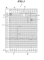
- FIG. 2 is a cross-sectional view taken along line XX in FIG. It is a top view which shows the structure of the board
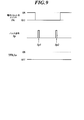
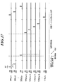
- 6 is a timing chart showing on / off timings of charge reset switches and TFTs in a leak data read process.
- 6 is a timing chart showing charge reset switches, pulse signals, and on / off timings of TFTs in a case where leak data reading processing and radiation detection element reset processing are alternately performed before radiographic imaging.
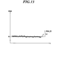
- 6 is a timing chart for explaining the timing of applying an ON voltage to each scanning line in the detection method 1; It is the graph which plotted the leak data read out in time series. It is a graph explaining the method of setting a threshold value based on the average value and standard deviation of each leak data. It is a graph explaining the method of setting a threshold value based on the difference between the average value and the maximum value and the minimum value of each leak data.
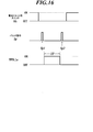
- 6 is a timing chart showing the timing of sequentially applying an ON voltage to each scanning line when the reading process of image data for detecting the start of irradiation is repeatedly performed in the detection method 2; 10 is a timing chart showing a charge reset switch, a pulse signal, TFT on / off timing, and an on time ⁇ T in a reading process of image data for irradiation start detection. 6 is a timing chart for explaining the timing of applying an ON voltage to each scanning line in the detection method 2; 12 is a timing chart for explaining timings for applying an ON voltage to each scanning line when the offset data reading process is performed by repeating the processing sequence shown in FIG.
- a radiographic imaging apparatus used in the radiographic imaging system a so-called indirect radiation that includes a scintillator or the like and converts the emitted radiation into electromagnetic waves of other wavelengths such as visible light to obtain an electrical signal.
- the image capturing apparatus will be described, the present invention can also be applied to a so-called direct type radiation image capturing apparatus that directly detects radiation with a radiation detection element without using a scintillator or the like.
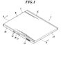
- FIG. 1 is a perspective view showing an external appearance of the radiographic image capturing apparatus
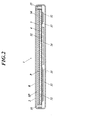
- FIG. 2 is a cross-sectional view taken along line XX of FIG.
- the radiographic image capturing apparatus 1 is configured by housing a sensor panel SP including a scintillator 3 and a substrate 4 in a housing 2.
- casing 2 is formed by obstruct
- the radiographic imaging device 1 is portable and is formed in a size compatible with the JIS standard CR cassette.
- the lid member 2 ⁇ / b> B on one side of the housing 2 includes a power switch 37, a changeover switch 38, a connector 39, a battery 24 (see FIG. 2 and FIG. 5 described later), and a radiographic imaging device.
- Indicator 40 etc. comprised by LED etc. which display 1 operation state etc. are arranged.
- an antenna device 41 (to be described later) is used for the radiographic imaging device 1 to transmit and receive signals and the like to and from an external device on the lid member 2C on the opposite side of the housing 2. 5) is provided so as to be embedded in the lid member 2C, for example.
- the antenna device 41 transmits the main image data D and the like from the radiographic image capturing device 1 to an external device such as a console 60 (see FIG. 7 described later) or the radiographic image capturing device 1 is an external device. It functions as a communication means for communicating with.
- a base 31 is disposed inside the housing 2 via a lead thin plate (not shown) on the lower side of the substrate 4, and an electronic component 32 and the like are disposed on the base 31.
- the PCB substrate 33, the battery 24, and the like are attached.
- a glass substrate 34 for protecting the substrate 4 and the radiation incident surface R of the scintillator 3 is disposed, and a buffer material 35 is provided between the sensor panel SP and the side surface of the housing 2. ing.
- each radiation detection element 7 made of a photodiode or the like is arranged two-dimensionally (matrix).
- Each radiation detection element 7 is connected to a thin film transistor (Thin Film Transistor, hereinafter referred to as TFT) 8 as a switching means, and further to a bias line 9. Further, each bias line 9 is bound to the connection 10 at a position outside the detection portion P of the substrate 4.
- TFT Thin Film Transistor
- each scanning line 5, each signal line 6, and connection 10 of the bias line 9 are input / output terminals (also referred to as pads) provided near the edge of the substrate 4. ) 11.
- each input / output terminal 11 has a flexible circuit board (Chip) in which chips such as a gate IC 15c and a readout IC 16 constituting a gate driver 15b of a scanning drive means 15 described later are incorporated on a film. 12 are connected via an anisotropic conductive adhesive material 13 such as an anisotropic conductive adhesive film (Anisotropic Conductive Film) or an anisotropic conductive paste (Anisotropic Conductive Paste).
- Chip flexible circuit board
- chips such as a gate IC 15c and a readout IC 16 constituting a gate driver 15b of a scanning drive means 15 described later are incorporated on a film.
- an anisotropic conductive adhesive material 13 such as an anisotropic conductive adhesive film (Anisotropic Conductive Film) or an anisotropic conductive paste (Anisotropic Conductive Paste).
- the flexible circuit board 12 is routed to the back surface 4b side of the substrate 4 and connected to the PCB substrate 33 described above on the back surface 4b side. Further, the scintillator 3 is provided so as to face the detection part P of the substrate 4. In this way, the sensor panel SP of the radiation image capturing apparatus 1 is formed.
- illustration of the electronic component 32 and the like is omitted.
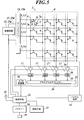
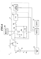
- FIG. 5 is a block diagram illustrating an equivalent circuit of the radiographic imaging apparatus 1 according to the present embodiment
- FIG. 6 is a block diagram illustrating an equivalent circuit for one pixel constituting the detection unit P.
- Each radiation detection element 7 of the detection unit P of the substrate 4 is connected to the second electrode 7b with a bias line 9, and each bias line 9 is bound to a connection 10 and connected to a bias power source 14.
- the bias power supply 14 applies a bias voltage to the second electrode 7 b of each radiation detection element 7 via the connection 10 and each bias line 9.
- the bias power supply 14 is connected to a control means 22 described later, and the control means 22 controls the bias voltage applied to each radiation detection element 7 from the bias power supply 14.
- the bias power supply 14 supplies the second electrode 7 b of the radiation detection element 7 to the first electrode 7 a side of the radiation detection element 7 as a bias voltage via the bias line 9.
- a voltage equal to or lower than the voltage applied to i.e., a so-called reverse bias voltage is applied.
- the scanning drive means 15 includes a power supply circuit 15a that supplies an on voltage and an off voltage to the gate driver 15b via the wiring 15d, and a voltage applied to each line L1 to Lx of the scanning line 5 between the on voltage and the off voltage.
- a gate driver 15b that switches between the on state and the off state of each TFT 8 is provided.
- Each signal line 6 is connected to each readout circuit 17 built in the readout IC 16.
- the readout circuit 17 includes an amplification circuit 18 and a correlated double sampling circuit 19.
- An analog multiplexer 21 and an A / D converter 20 are further provided in the read IC 16. 5 and 6, the correlated double sampling circuit 19 is represented as CDS. In FIG. 6, the analog multiplexer 21 is omitted.
- the amplifier circuit 18 is a charge amplifier circuit including an operational amplifier 18a, a capacitor 18b and a charge reset switch 18c connected in parallel to the operational amplifier 18a, and a power supply unit 18d that supplies power to the operational amplifier 18a and the like. It consists of The signal line 6 is connected to the inverting input terminal on the input side of the operational amplifier 18 a of the amplifier circuit 18, and the reference potential V 0 is applied to the non-inverting input terminal on the input side of the amplifier circuit 18. . Note that the reference potential V 0 is set to an appropriate value, and in this embodiment, for example, 0 [V] is applied.
- the charge reset switch 18c of the amplifier circuit 18 is connected to the control means 22, and is controlled to be turned on / off by the control means 22. Further, a switch 18e that opens and closes in conjunction with the charge reset switch 18c is provided between the operational amplifier 18a and the correlated double sampling circuit 19, and the switch 18e is turned on / off by the charge reset switch 18c. It is designed to be turned off / on in conjunction with
- the charge reset switch 18c When the radiation image capturing apparatus 1 performs the reset process of each radiation detection element 7 for removing the charge remaining in each radiation detection element 7, the charge reset switch 18c is turned on (and switched). Each TFT 8 is turned on in a state where 18e is turned off.
- a voltage value corresponding to the amount of charge accumulated in the capacitor 18b is output from the output side of the operational amplifier 18a.
- the correlated double sampling circuit (CDS) 19 outputs the voltage value Vin output from the amplifier circuit 18 at that time. Hold.
- the image data D of each radiation detection element 7 output from the correlated double sampling circuit 19 is sequentially transmitted to the A / D converter 20 via the analog multiplexer 21, and the digital value is sequentially converted by the A / D converter 20. It is converted into image data D, outputted to the storage means 23 and sequentially stored.
- the charge reset switch 18c of the amplifier circuit 18 When one image data read-out process is completed, the charge reset switch 18c of the amplifier circuit 18 is turned on, and the charge accumulated in the capacitor 18b is discharged. Passes through the operational amplifier 18a from the output terminal side of the operational amplifier 18a, goes out from the non-inverting input terminal, is grounded, or flows out to the power supply unit 18d, etc., so that the amplifier circuit 18 is reset.
- the control means 22 includes a CPU (Central Processing Unit) (not shown), a ROM (Read Only Memory), a RAM (Random Access Memory), a microcomputer in which an input / output interface is connected to a bus, an FPGA (Field Programmable Gate Array), and the like. It is comprised by. And the control means 22 controls operation
- a CPU Central Processing Unit
- ROM Read Only Memory
- RAM Random Access Memory
- FPGA Field Programmable Gate Array
- control means 22 is connected to a storage means 23 composed of SRAM (Static RAM), SDRAM (Synchronous DRAM) or the like.
- control unit 22 is connected to the antenna device 41 described above, and further connected to the power switch 37, the changeover switch 38, the connector 39, the indicator 40 (see FIG. 1), and the like. ing.
- control means 22 is connected to a battery 24 for supplying electric power to each function unit such as the control means 22, the scanning drive means 15, the readout circuit 17, the storage means 23, and the bias power supply 14.
- the connector 39 is connected to the battery 24 so that the battery 24 can be charged via the connector 39.
- the present inventors have found a new technique for detecting the start of radiation irradiation with the radiographic imaging apparatus 1 having the above-described configuration.
- the configuration of the system 100 will be described later.
- FIG. 7 is a diagram illustrating a configuration of the radiographic image capturing system according to the present embodiment.
- the radiographic imaging system 100 is constructed
- the radiographic image capturing apparatus 1 includes, for example, a bed B installed in a hospital room Rc and a body of a patient B lying on the bed B. It is designed to be used by inserting it in between or directly on the patient's body. Therefore, when positioning the radiographic image capturing apparatus 1, an impact or the like is easily applied to the housing 2.
- the housing 2 has a size compatible with the CR cassette as described above, since the inside of the housing 2 becomes narrow, the arrangement of the buffer member is restricted. Therefore, when the shock is received, the shock is generated. There is a possibility of affecting the photographed image.
- the round wheel 51 is equipped with a radiation generator 52.
- a portable radiation source 53 that irradiates the radiation image capturing apparatus 1 with radiation through the body of the patient B, that is, the subject, is connected to the radiation generating apparatus 52.
- the radiation generator 52 is provided with an exposure switch 54 that is operated by the radiation engineer E to instruct the radiation source 53 to start radiation irradiation.
- the exposure switch 54 for example, an exposure switch of a type in which a button (not shown) is operated in two stages, such as the conventional exposure switch described above, can be used.
- the radiation generating device 52 is provided with an access point (also referred to as a wireless antenna) 55 for performing wireless communication with the antenna device 41 (see FIG. 5) of the radiation image capturing device 1.
- the access point 55 is connected to a repeater (not shown) provided inside the radiation generator 52.
- the repeater relays communication by the LAN (Local Area Network) between the radiographic image capturing apparatus 1 and the portable terminal 70 and console 60 described later, and a LAN communication signal or the like is used as a signal for the radiation generation apparatus 52 or the like.
- the communication between the console 60 and the radiation generator 52 is relayed by performing conversion or vice versa.
- a holder 56 for inserting the radiographic image capturing apparatus 1 and transporting the radiographic image capturing apparatus 1 together with the round wheel 51 is provided on the side surface of the radiation generating apparatus 52.
- the holder 56 in the form of a pocket so as to simply hold the radiographic image capturing apparatus 1.
- the radiographic image capturing apparatus is used.
- 1 connector 39 (see FIG. 1) and a connector (not shown) provided in the holder 56 are connected so that the battery 24 (see FIG. 2 and FIG. 5) of the radiographic imaging apparatus 1 is automatically charged. It has become.
- the radiographic image capturing apparatus 1 supplies the power to each functional unit such as the scanning drive unit 15 and the readout circuit 17 (see FIG. 5) as the power consumption state of the battery 24, and captures the radiographic image. Power is supplied only to necessary functional parts such as the antenna device 41 and the scan enable means 15 and the readout circuit 17 etc.
- the power consumption mode can be switched between a sleep mode (also referred to as a power saving mode) that does not supply power.
- the power consumption mode of the radiographic imaging device 1 is set to the sleep mode, but the radiographic imaging device 1 is in the holder.
- the radiographic image capturing apparatus 1 automatically shifts to the radiographable mode.
- a console 60 is placed on the radiation generator 52 of the round-trip wheel 51.
- the console 60 is connected to the radiation generation device 52 and the access point 55 via the repeater, and can communicate with the radiation image capturing device 1 and the portable terminal 70 described later via the access point 55. It can be done.
- the console 60 is composed of a computer including a CPU (not shown).
- the console 60 is provided with a display unit 61 including a CRT (Cathode Ray Tube), an LCD (Liquid Crystal Display) and the like, and a memory constituted by an HDD (Hard Disk Drive) or the like.
- Means 59 are connected or built in.
- the console 60 basically generates a preview image based on the data for the preview image transmitted from the radiographic image capturing apparatus 1, and displays the generated preview image on the display unit 61. It is supposed to let you.
- a diagnostic radiation image is generated by performing predetermined image processing such as gradation processing.
- the radiographic image capturing apparatus 1 erroneously detects the start of radiation irradiation, reads the main image data D, and transmits data for the preview image based thereon. In such a case, the data is not accepted.
- This point will be described in detail after describing a new technique for detecting the start of radiation irradiation in the radiation imaging apparatus 1 itself found by the present inventors.
- the radiographic imaging apparatus 1 is inserted between the bed B and the patient B's body or directly applied to the patient's body.
- the portable terminal 70 that wirelessly transmits a completion signal to the console 60. Is provided.
- the mobile terminal 70 is basically carried by the radiologist E. Then, as shown in FIG. 7, for example, it is preferable that the portable terminal 70 is hung from the neck of the radiographer E by a strap 72 so that the positioning of the radiographic imaging apparatus 1 is not hindered.
- a portable information terminal such as iPad (registered trademark) capable of input operation can be used as the portable terminal 70.
- the portable terminal 70 preferably has a display screen 71 as shown in FIG. 7, but this point will be described later.
- the mobile terminal 70 does not necessarily need to be a commercially available general-purpose information terminal such as iPad (registered trademark), and may be a dedicated mobile information terminal that is portable and capable of input operation.
- the mobile terminal 70 may be a simple switch including an antenna device or the like.
- the leak data dleak is a charge q leaked from each radiation detection element 7 via each TFT 8 which is in an OFF state in a state where an OFF voltage is applied to each scanning line 5. This data corresponds to the total value for each signal line 6.
- the readout circuit 17 is made to perform a readout process in a state where an off voltage is applied to each of the lines L1 to Lx of the line 5 to turn off the respective TFTs 8.
- each TFT 8 is turned off by applying an off voltage to each of the lines L1 to Lx of the scanning line 5
- the correlation circuit of each readout circuit 17 from the control means 22 is correlated.
- Pulse signals Sp1 and Sp2 are transmitted to the sampling circuit 19 (see CDS in FIG. 5).
- the correlated double sampling circuit 19 holds the voltage value Vin output from the amplifier circuit 18 at that time.
- the charge q leaked from each radiation detection element 7 via each TFT 8 is accumulated in the capacitor 18b of the amplifier circuit 18 to increase the voltage value output from the amplifier circuit 18, and the pulse signal Sp2 is transmitted from the control means 22.
- the correlated double sampling circuit 19 holds the voltage value Vfi output from the amplifier circuit 18 at that time.
- the value that the correlated double sampling circuit 19 calculates and outputs the voltage value difference Vfi ⁇ Vin becomes the leak data dleak.
- the leak data dleak is then converted into a digital value by the A / D converter 20 as in the case of the image data D reading process described above. In this way, the reading process of the leak data dleak is performed.
- each TFT 8 remains in an off state, and the dark charge generated in each radiation detection element 7 is continuously accumulated in each radiation detection element 7. Become.
- the leakage data dleak is read out with the off voltage applied to each scanning line 5, and the on voltage is sequentially applied to each line L1 to Lx of the scanning line 5. It is desirable that the reset processing of each radiation detection element 7 performed by applying is alternately performed. Note that T and ⁇ in FIG. 10 and FIG. 11 described later will be described later.
- each TFT 8 is irradiated with electromagnetic waves converted from radiation by the scintillator 3 (see FIG. 2).
- FIG. 11 and 12 the leak data dleak read in the fourth read process after the on-voltage is applied to the line L4 of the scanning line 5 in FIG. 11 and the reset process is performed is shown in FIG. Corresponds to the leak data dleak at time t1.
- “R” represents a reset process of each radiation detection element 7
- “L” represents a read process of leak data dleak. Note that Tac in FIG. 11 will be described later.
- control means 22 of the radiographic image capturing apparatus 1 is configured to monitor the leak data dleak read out in the read processing of the leak data dleak before radiographic image capture, and the read out leak data dleak is, for example, It may be configured to detect that radiation irradiation has started when a predetermined threshold value dleak_th (see FIG. 12) set in advance is exceeded.
- the threshold value dleak_th As shown in FIG. 12, the value of the leak data dleak read in a state where the radiation imaging apparatus 1 is not irradiated with radiation (that is, the value of the leak data dleak before time t1) is a substantially constant value. The value will fluctuate slightly. If the leak data dleak fluctuating in this way exceeds the threshold value dleak_th, it is erroneously detected that radiation irradiation has started even though radiation has not been irradiated. Therefore, the threshold value dleak_th needs to be set to a value that does not exceed the fluctuation data bleak that fluctuates in this way.
- the value of the leak data dleak read out in a state where the radiation image capturing apparatus 1 is not irradiated with radiation is stabilized, the value is read out by a predetermined number of reading processes.
- the average value da of the leak data dleak is calculated.
- a standard deviation ⁇ is calculated as the degree of fluctuation of each leak data dleak.
- a value da + 8 ⁇ obtained by adding a value (for example, 8 ⁇ ) obtained by multiplying the average value da of the leak data dleak by a predetermined value such as 8 times (for example, 8 ⁇ ) to the average value da is calculated, and the value is set as the threshold value dleak_th. ing.
- the threshold value dleak_th is a value obtained by multiplying the average value da of the leak data dleak by a predetermined value such as eight times the difference ⁇ dleak between the maximum value and the minimum value of the leak data dleak (for example, A value da + 8 ⁇ ⁇ dleak obtained by adding (8 ⁇ ⁇ dleak) is calculated and set.
- the threshold value dleak_th for the leak data dleak is set in advance as described above. In the above case, the magnification for multiplying the standard deviation ⁇ and the difference ⁇ dleak by a predetermined value is determined as appropriate. Further, the threshold value dth for the image data d in the detection method 2 described below is set in the same manner.
- the gate of the scanning drive unit 15 is configured before the radiographic image is captured as illustrated in FIG. 15. It is also possible to apply a turn-on voltage sequentially to each of the lines L1 to Lx of the scanning line 5 from the driver 15b and to read out the image data d for detecting the start of irradiation from each of the radiation detection elements 7.
- the image data d is read out before radiographic image capturing as described above, when radiation irradiation to the radiographic image capturing device 1 is started as shown in FIG.
- the image data d (in FIG. 17, the image data d read by applying the on-voltage to the line Ln of the scanning line 5) is the same as before the leak data dleak shown in FIG.
- the image data d is much larger than the image data d read out.
- control means 22 of the radiographic image capturing apparatus 1 is configured to monitor the image data d read in the read process before radiographic image capturing, and the read image data d is set to a predetermined value set in advance. It can be configured to detect that radiation irradiation has started when the threshold value dth is exceeded.
- the period ⁇ of each read process of the leak data dleak and each read process of the image data d (FIG. 10). 11 and FIG. 17), the transmission interval T of the pulse signals Sp1 and Sp2 (see FIG. 10 and FIG. 11), or the time ⁇ T during which the on-voltage is applied to the TFT 8 can be lengthened. .
- control means 22 When the control means 22 detects the start of radiation irradiation as described above, as shown in FIG. 11, the control means 22 stops the application of the on-voltage to each scanning line 5 at that time, and the gate An off voltage is applied from the driver 15b to each of the lines L1 to Lx of the scanning line 5, each TFT 8 is turned off, and the charge generated in each radiation detecting element 7 by radiation irradiation is accumulated in each radiation detecting element 7. It is made to shift to the charge accumulation state.
- the control unit 22 starts the irradiation of the radiation, for example, in the reading process of the leak data dleak before the radiographic image capturing.
- the scanning line 5 to which the on-voltage is to be applied next to the scanning line 5 (the line L4 of the scanning line 5 in the case of FIG. 16) to which the on-voltage has been applied in the reset process immediately before the detection is detected.
- the application of the on-voltage is started from the line L5) of the scanning line 5, and the on-voltage is sequentially applied to each scanning line 5 so as to perform the reading process of the image data D as the main image, that is, the main image data D. It has become.
- the control unit 22 when radiographic imaging is performed and the main image data D is read from each radiation detection element 7, the control unit 22 firstly specifies, for example, 1 / The main image data D read from the four radiation detection elements 7, that is, the radiation detection elements 7 connected to the lines L 1, L 5, L 9,. Data is automatically transmitted to the console 60 (see FIG. 7) via the antenna device 41 (see FIG. 5).
- control unit 22 performs the process up to the reading process of the main image data D shown in FIG. 11 after the reading process of the main image data D and the transmission of the preview image data, as shown in FIG. The same processing sequence as the processing sequence is repeated to read the offset data O from each radiation detection element 7.
- the reading process of the offset data O is performed in a state where the radiation image capturing apparatus 1 is not irradiated with radiation, and is superimposed on the image data D read from each radiation detecting element 7 as described above. Data corresponding to the offset due to the so-called dark charge is read as offset data O.
- control means 22 will complete
- the processing immediately before the reading processing of the main image data D shown in FIG. The time from when the on-voltage is applied to the TFT 8 to the time when the on-voltage is applied in the reading process of the main image data D (hereinafter referred to as effective accumulation time) Tac and the reading process of the offset data O shown in FIG.
- effective accumulation time Tac at the same time is the same for each scanning line 5.
- the amount of dark charge read from each radiation detection element 7 depends on the time during which the TFT 8 connected to the radiation detection element 7 is in the off state, that is, the effective accumulation time Tac in FIGS. Although it fluctuates, if the effective accumulation time Tac is the same, the amount of dark charge read from each radiation detection element 7 becomes the same amount.
- the reading process of the main image data D (FIG. 11) is performed.
- the effective accumulation time Tac is the same for each scanning line 5 in the reading process (see FIG. 18) and the offset data O reading process (see FIG. 18).
- the power consumption mode is set to the sleep mode. To shootable mode.
- the radiographer E who has extracted the radiographic image capturing apparatus 1 from the holder 56 operates the changeover switch 38 (see FIG. 1) to manually switch the power consumption mode of the radiographic image capturing apparatus 1 to the radiographable mode. It is also possible to configure as described above. Further, when the radiographer E turns on the power switch 27, the power consumption mode of the radiographic image capturing apparatus 1 can be changed to the radiographable mode.
- the radiographic image capturing apparatus 1 When the power consumption mode is changed to the imageable mode in this way, the radiographic image capturing apparatus 1 performs a leak data dleak read process and a reset process for each radiation detection element 7 as shown in FIGS. It will be in a state of repeating alternately. Then, as shown in FIG. 7, the radiographic imaging device 1 is positioned by the radiologist E so as to be inserted between the bed B and the body of the patient B or directly applied to the patient's body, for example.
- the radiographer E operates the portable terminal 70 when the positioning of the radiographic image capturing apparatus 1 is completed, and transmits a completion signal from the portable terminal 70 to the console 60. Then, the radiation imaging device 1 is moved to the radiation generating device 52 on the round wheel 51, and the exposure switch 54 is operated to irradiate the radiation imaging apparatus 1 from the radiation source 53 through the subject.
- the read leak data dleak may increase due to the impact as described above.
- the control means 22 of the radiographic imaging device 1 detects that radiation irradiation has been started as described above (in this case, erroneous detection), as shown in FIG.
- the gate driver 15b applies an off voltage to each of the lines L1 to Lx of the scanning line 5 to shift to a charge accumulation state, and after a predetermined time has elapsed, the on voltage is sequentially applied to each of the scanning lines 5 to generate the main image data. D is read out.
- the control means 22 reads from each radiation detection element 7 designated in advance such as 1 ⁇ 4 of all the radiation detection elements 7.
- the read main image data D is automatically transmitted to the console 60 as preview image data.
- the radiation image capturing apparatus 1 is not actually irradiated with radiation, and the body part of the patient H as the subject is not captured at all in the main image data D. Therefore, the read main image data D is unnecessary data.
- the console 60 itself cannot determine whether the transmitted preview image data is unnecessary.
- the radiographer E inserts the radiographic image capturing apparatus 1 between the bed B and the patient B body, or directly applies the radiographic image capturing apparatus 1 to the patient body.
- the portable terminal 70 is operated, and the completion signal transmitted from the portable terminal 70 to the console 60 is used as a trigger for the preview image transmitted from the radiation image capturing apparatus 1 to the console 60. It is made to judge acceptance or rejection of data reception.
- the console 60 does as described above until a completion signal is transmitted from the portable terminal 70 (that is, in a stage before receiving the completion signal).
- a completion signal is transmitted from the portable terminal 70 (that is, in a stage before receiving the completion signal).
- the data for the preview image is transmitted from the radiation image capturing apparatus 1
- a cancellation signal is transmitted with respect to the said radiographic imaging apparatus 1.
- the control unit 22 of the radiographic image capturing apparatus 1 When receiving the cancel signal from the console 60, the control unit 22 of the radiographic image capturing apparatus 1 performs a series of processes performed at that time, for example, when the offset data O is read out, the offset is set. The reading process of the data O is stopped, and when the transmission of the main image data D and the offset data O has already been started, the transmission process is stopped.
- the control unit 22 of the radiographic image capturing apparatus 1 stores the main image data D (and the offset data O when the offset data O is read) stored in the storage unit 23 as the storage unit.
- the main image data D (and offset data O) stored therein may be set with a flag indicating that overwriting is possible, and the main image data D read out after that is stored. Etc. can also be configured to be overwritten and saved in the main image data D or the like.
- the console 60 completes the positioning of the radiographic image capturing apparatus 1 by the radiologist E, operates the mobile terminal 70, and transmits a completion signal from the mobile terminal 70.
- the data for use is transmitted, it is determined that the radiation image capturing apparatus 1 has been irradiated with radiation, and the radiation image capturing apparatus 1 has successfully detected the start of radiation irradiation.
- a cancel signal is not transmitted to the radiographic image capturing apparatus 1 and, as described above, based on the transmitted preview image data, for example, each radiation detection element 7 from the preview image data.
- Preset offset data is subtracted every time, or, among the offset data O transmitted from the radiographic image capturing apparatus 1 in the previous imaging, the offset data O for each of the radiation detecting elements 7 is used for the preview image. Subtract from the data.
- the console 60 performs simple image processing such as logarithmic conversion of the subtracted value, generates a preview image, and displays the generated preview image on the display unit 61 (see FIG. 7). .
- each TFT 8 is turned off to shift to a charge accumulation state and ready for radiation irradiation. To wait until the radiologist E receives radiation from the radiation source 53.
- the radiation image capturing apparatus 1 itself detects and determines the start of radiation irradiation. Then, as shown in FIG. 11 and the like, the read processing of the main image data D is started after a charge accumulation state for a predetermined time after detecting the start of radiation irradiation.
- the radiation image capturing apparatus 1 detects the radiation irradiation start based on the leak data dleak (or image data d for irradiation start detection) read out before the radiation image capturing. If an impact is applied to the radiation image capturing apparatus 1 during positioning of the image capturing apparatus 1, the read leak data dleak may increase due to the impact as described above.
- the radiographic imaging device 1 erroneously detects the start of radiation irradiation.
- the console 60 itself cannot determine whether the preview image data transmitted from the radiographic image capturing apparatus 1 is due to erroneous detection.
- the radiographer E inserts the radiographic image capturing apparatus 1 between the bed B and the patient B body, or directly applies the radiographic image capturing apparatus 1 to the patient's body.
- the console 60 is configured to determine whether or not the preview image data transmitted from the radiographic image capturing apparatus 1 is due to erroneous detection before and after the completion of the positioning.
- the preview image is displayed before the radiation technician E completes positioning of the radiographic imaging device 1.
- the transmitted data for the preview image is due to erroneous detection.
- the transmitted data for the preview image is based on normal detection, and the subject is accurately detected. It can be considered that it is based on the photographed main image data D.
- the radiographer E can recognize it, so it waits for several seconds without irradiating the radiation, and a preview is displayed on the display unit 61 of the console 60. What is necessary is just to confirm whether an image is displayed. If no preview image is displayed, assuming that no erroneous detection has occurred, the exposure switch 54 (see FIG. 7) may be operated to perform shooting.
- the radiographic imaging device 1 stops the process of performing the offset data O when the process being performed at that time, for example, the process of reading the offset data O is performed, If transmission of the main image data D and offset data O has already been started, the transmission process is stopped, and the reading process of the leak data dleak before the radiographic image capturing and the reset process of each radiation detection element 7 are resumed. Will come to let you. Then, if the radiologist E operates the exposure switch 54 (see FIG. 7), imaging can be performed.
- the radiographic image capturing apparatus 1 performs the reading process of the leak data dleak and the reading process of the image data d for irradiation start detection before capturing the radiographic image.
- the start of radiation irradiation is detected based on the read leak data dleak and the like.
- each TFT 8 is in the OFF state after detecting the start of radiation irradiation is prevented from being unnecessarily long, and the power of the battery 24 (see FIG. 5 and the like) is consumed more than necessary. Accurately prevented.
- the amount of dark charge accumulated in each radiation detection element 7 increases and the S / It is possible to accurately prevent problems such as deterioration of the N ratio.
- the console 60 does not receive a completion signal from the portable terminal 70 (that is, before the radiographer E completes positioning of the radiographic imaging device 1).
- the radiographic image capturing apparatus 1 transmits a cancel signal to the radiographic image capturing apparatus 1 assuming that the start of radiation irradiation is erroneously detected.
- the radiographic imaging device 1 stops the processing being performed at that time, and restarts the reading processing of the leak data dleak before the radiographic imaging or the reading processing of the image data d for irradiation start detection.
- the console 60 has received the preview image data from the radiographic image capturing apparatus 1 after the radiographer E has completed the positioning of the radiographic image capturing apparatus 1 and has transmitted a completion signal from the portable terminal 70.
- a preview image is generated based on the data for the preview image and displayed on the display unit 61.
- a completion signal is transmitted from the portable terminal 70 based on whether or not a completion signal has been transmitted from the portable terminal 70, that is, whether or not the radiographer E has completed positioning of the radiation imaging apparatus 1. If the data for the preview image is transmitted before the radiographer E completes the positioning of the radiographic imaging apparatus 1, it is accurately determined that it is due to erroneous detection, and the radiation It is possible to accurately stop the series of processing in the image capturing apparatus 1. Then, it is possible to return the radiographic image capturing apparatus 1 to a state in which the read processing of the leak data dleak before the radiographic image capturing and the read processing of the image data d for irradiation start detection are performed.
- the radiologist E does not need to wait for the reading process of the main image data D or the reading process of the offset data O based on the erroneous detection, but immediately operates the exposure switch 54 to perform original imaging. It becomes possible. Therefore, the entire radiographic image capturing system 100 including the radiographic image capturing apparatus 1 is convenient for the radiographer E.
- the console 60 determines that the radiation image capturing apparatus 1 has detected the start of radiation irradiation normally, generates a preview image based on the preview image data, and causes the display unit 61 to display the preview image. Then, as shown in FIG. 19, when the remaining main image data D and offset data O are further transmitted from the radiographic image capturing apparatus 1, as described above, offset correction and correction are performed on the main image data D and the like. Predetermined image processing such as gain correction, defective pixel correction, and gradation processing is performed to generate a radiation image (medical image) and display it on the display unit 61.
- the console 60 causes the radiographic image capturing apparatus 1 to discard the main image data D for re-imaging, stops a series of processes performed at that time, and reads leak data dleak before radiographic image capture and The reset process of each radiation detection element 7 is resumed.
- the console 60 receives the preview image data based on the erroneous detection from the radiographic image capturing apparatus 1 before the completion signal is transmitted from the portable terminal 70, as described above.
- a cancel signal is transmitted to the radiation image capturing apparatus 1, and at the same time, for example, a preview image for the mobile terminal 70 is generated by performing a thinning process on the data for the preview image.
- the preview image can be configured to be transmitted to the mobile terminal 70.
- the preview image displayed on the display screen 71 of the mobile terminal 70 is an abnormal image.
- the radiologist E looks at such a preview image, the radiologist E can accurately recognize that the radiation image capturing apparatus 1 has erroneously detected the start of radiation irradiation due to an impact or the like.
- the radiographic image capturing apparatus 1 normally detects the start of radiation irradiation, and the normal main image data D, that is, preview image data based on the main image data D in which the subject is captured is consoled.
- the radiologist E looks at the preview image displayed on the display unit 61 of the console 60 and determines whether to approve or reject the preview image. It is also possible to configure to be performed on the terminal 70.
- the generated preview image is transmitted from the console 60 to the portable terminal 70.
- the portable terminal 70 for example, as shown in FIG.
- the preview image p_pre, the “OK” button 71 a and the “NG” button 71 b are displayed on the display screen 71.
- the radiologist E confirms the displayed preview image p_pre, and touches the “OK” button 71a to approve the preview image p_pre, and touches the “NG” button 71b to reject the preview image p_pre. Or enter a denial.
- the portable terminal 70 transmits a signal corresponding to the input to the console 60.
- the console 60 performs the same processing as when the approval or denial is directly input to the console 60 itself. Composed.
- the radiographer E will stay at the round-trip wheel 51 (refer FIG. 7) in which the console 60 was mounted after imaging
- the preview image p_pre displayed on the display screen 71 of the mobile terminal 70 is displayed while performing processing such as changing the position where the radiation image capturing apparatus 1 is directly applied to the patient H for the next imaging. It becomes possible to confirm.
- the radiographic image capturing system 100 including the radiographic image capturing apparatus 1 becomes more convenient.
- the threshold value dleak (see FIG. 12) and the threshold value dth that are used when the radiation imaging apparatus 1 detects the start of irradiation of radiation are shown in FIG. Even if high values of leak data dleak or the like are read out due to an impact or the like by setting a value higher than the normal threshold values dleak_th and dth set by the setting method shown in FIG. It can be configured not to exceed.
- the console 60 indicates that the completion signal has been received when the completion signal is transmitted from the portable terminal 70.
- the signal is transmitted to the radiation image capturing apparatus 1. You may comprise so that a completion signal may be transferred to the radiographic imaging apparatus 1 as it is.
- the control unit 22 sets the threshold value dleak_th, for example, 20 times the standard deviation ⁇ shown in FIG. Is set to a value obtained by adding to the average value da of the leak data dleak, and the radiation irradiation start detection process is performed based on the set threshold dleak.
- the control means 22 leaks the threshold value “dleak_th”, for example, a value that is, for example, eight times the standard deviation ⁇ as shown in FIG. It is possible to set the value added to the average value da of the data dleak and to perform the radiation irradiation start detection process based on the set threshold value dleak.
- the control means 22 of the radiographic imaging device 1 is based on the threshold value leak_th of the normal value as described above. Thus, it is accurately detected whether or not radiation irradiation has started.
- the value of the threshold value dleak_th or the like becomes high until a signal indicating that the completion signal has been received from the console 60, even if high value leak data dleak or the like is read due to an impact or the like, it is read out. It is possible to accurately reduce the probability that the leak data dleak etc. exceeds the threshold dleak_th etc.
- the frequency at which the radiation image capturing apparatus 1 erroneously detects the start of radiation irradiation can be accurately reduced.
- the power switch 37 may be operated to turn on the radiation image capturing apparatus 1.
- the radiologist E forgets to turn on the radiographic image capturing apparatus 1 after extracting the radiographic image capturing apparatus 1 from the holder 56, and the radiographic image capturing apparatus 1 with the power off remains in the patient. If radiation is irradiated, for example, by direct application to the body of H (see FIG. 7), erroneous exposure occurs, and radiation is wasted.
- an erroneous exposure prevention means 80 as shown in FIG. May be provided.
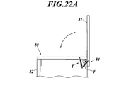
- the erroneous exposure prevention means 80 for example, as shown in FIG. 21, a cover provided in a casing shape surrounding the exposure switch 54 can be used. And the erroneous exposure prevention means 80 is provided with the cover part 81 and the support plate 82, for example, and it can be comprised so that the cover part 81 can be opened and closed with respect to the support plate 82.
- FIG. 21 a cover provided in a casing shape surrounding the exposure switch 54 can be used.
- the erroneous exposure prevention means 80 is provided with the cover part 81 and the support plate 82, for example, and it can be comprised so that the cover part 81 can be opened and closed with respect to the support plate 82.
- the support plate 82 can also be configured by a total of two plate-like members standing in parallel one by one on both sides of the exposure switch 54 in a state of being housed in the holder 83, You may be comprised so that the exposure switch 54 of the state accommodated in the holder 83 may be enclosed from three or four directions. And the cover part 81 is attached so that opening and closing is possible via the hinge structure 84 provided in the one end side of the upper part of the support plate 82. As shown in FIG.
- a tumbler spring T can be provided on the hinge structure 84 of the erroneous exposure preventing means 80.
- the lid 81 is urged by the tumbler spring T so that the lid 81 is closed.
- the radiologist E opens the lid 81 around the rotation axis F to a predetermined position or more.
- the lid 81 can be biased so as to be in the open state.
- the radiation technician E operates the exposure switch 54 to irradiate the radiation with respect to the erroneous exposure prevention means 80.
- An opening operation must be performed. Then, when performing an opening operation on the erroneous exposure prevention means 80, it is possible to recall that the radiographer E turns on the power of the radiographic imaging apparatus 1, and the radiographic imaging apparatus with the power off. It is possible to prevent the radiation 1 from being accidentally exposed to radiation.
- the radiation technician E opens the lid 81 of the erroneous exposure prevention means 80 from now on. 1 can be regarded as a kind of cue indicating that radiation is applied to 1. Until this signal is given, the radiation image capturing apparatus 1 is not irradiated with radiation.
- the power consumption mode of the radiographic imaging device 1 is set to the sleep mode, and the radiographer E performs the erroneous exposure prevention unit.
- the power consumption mode of the radiographic image capturing apparatus 1 is changed to the radiographable mode, and the reading process of leak data dleak before radiographic image capturing is started.
- the control unit 22 of the radiographic image capturing apparatus 1 performs radiation even if an impact is applied to the radiographic image capturing apparatus 1. It is possible to prevent erroneous detection of the start of irradiation. Therefore, in order to realize this, it is possible to configure as follows.
- the optical detection means 85 including the light emitting element 85a and the light receiving element 85b is reflected by the lid 81 in which the light emitted from the light emitting element 85a is opened to receive the light receiving element. It arrange
- a detection means for detecting contact with the lid 81 is provided at the upper end of the support plate 82 of the erroneous exposure prevention means 80, and the lid 81 and the support plate 82 are It is also possible to configure the detection unit to transmit an opening signal to the console 60, assuming that the lid 81 is opened when contact is lost.
- the console 60 is operated to open the accidental exposure prevention means 80 by the radiation technician E, and the exposure switch 54 is operated.
- a wakeup signal is transmitted to the radiation image capturing apparatus 1.
- the radiographic image capturing apparatus 1 When the radiographic image capturing apparatus 1 receives the awakening signal from the console 60, the radiographic image capturing apparatus 1 shifts the power consumption mode from the sleep mode to the radiographable mode, and performs processing for reading leak data dleak before radiographic image capturing and for detecting irradiation start. It is possible to configure to start the reading process of the image data d.
- the power consumption mode of the radiographic imaging apparatus 1 is the sleep mode.
- the control means 22 of the radiographic imaging apparatus 1 is accurately prevented from erroneously detecting the start of radiation irradiation.
- the console 60 transmits data for the preview image from the radiation image capturing apparatus 1 due to erroneous detection to the radiation image capturing apparatus 1.
- the cancel signal is transmitted and the completion signal is transmitted from the portable terminal 70
- the preview image data transmitted from the radiographic image capturing apparatus 1 is received. As explained in.
- the threshold value dleak_th and the threshold value dth may be switched from a high value to a normal value before and after the completion signal is transmitted from the mobile terminal 70. is there.
- the radiation engineer E forgets to turn on the power of the radiographic imaging device 1 when performing the opening operation on the erroneous exposure prevention means 80, and the erroneous exposure prevention means 80
- the radiation image capturing apparatus 1 may be turned on after the opening operation is performed.
- the power consumption mode of the radiographic imaging apparatus 1 is the sleep mode immediately after the power is turned on, but since the awakening signal has already been transmitted from the console 60 at this time, the power of the radiographic imaging apparatus 1 is The consumption mode is immediately switched to the photographable mode.
- the configuration is such that the erroneous detection before the completion signal is transmitted from the portable terminal 70 to the console 60 is not generated as much as possible.
- the power consumption mode of the radiographic imaging device 1 is set to the sleep mode, and the radiation irradiation start detection process is not performed. It will be good.
- the power consumption mode of the radiographic imaging device 1 is changed to the radiographable mode. It is possible to configure.
- the radiographic imaging device 1 is configured so that the power consumption mode can be switched between the radiographable mode and the sleep mode, for example, radiographic imaging.
- the power switch 37 (see FIG. 1) of the apparatus 1 is turned on, the radiographic image capturing apparatus 1 is configured to be in a sleep mode.
- the power consumption mode of the radiographic image capturing apparatus 1 is in the sleep mode. Therefore, as in the first embodiment, radiation is caused by erroneous detection. Data for the preview image is not transmitted from the image capturing apparatus 1. Therefore, a cancel signal is not transmitted from the console 60 to the radiographic image capturing apparatus 1.
- the radiographer E positions the radiographic image capturing apparatus 1 by directly applying the sleep mode radiographic image capturing apparatus 1 to the body of the patient H (see FIG. 7).
- the console 60 awakens to the radiographic imaging apparatus 1. Send.
- the radiographic image capturing apparatus 1 receives the awakening signal from the console 60, the radiographic image capturing apparatus 1 switches the power consumption mode from the sleep mode to the image capture enable mode, and starts the leak data dleak read processing and the like.
- control unit 22 of the radiographic image capturing apparatus 1 detects the start of radiation irradiation based on the read leak data dleak or the like (FIG. 11). After the transition to the charge accumulation state, the main image data D is read from each radiation detection element 7.
- a part of the read main image data D is transmitted to the console 60 as preview image data. Further, for example, the offset data O is read as shown in FIG. 18, and the remaining main image data D and offset data O are transmitted to the console 60.
- the console 60 when the data for the preview image is transmitted from the radiation image capturing apparatus 1, the console 60 generates a preview image p_pre based on the data for the preview image and displays it on the display unit 61. If the preview image p_pre is denied by the radiographer E, the console 60 causes the radiographic image capturing apparatus 1 to discard the main image data D for re-imaging, and stops a series of processes performed at that time. Thus, the read processing of the leak data dleak before the radiographic image capturing is restarted.
- the console 60 If the preview image p_pre is approved, the console 60 generates a radiation image based on the transmitted main image data D and offset data O, and causes the display unit 61 to display the generated radiation image.
- the time point when the radiologist E completes positioning of the radiographic imaging apparatus 1 and a completion signal is transmitted from the portable terminal 70 to the console 60 is a boundary.
- the power consumption mode of the radiographic image capturing apparatus 1 is shifted to the sleep-capable mode.
- the radiologist E places the radiation image capturing apparatus 1 directly on the body of the patient H to position the radiation image capturing apparatus 1, even if an impact is applied to the radiation image capturing apparatus 1, Since the power consumption mode of the radiation image capturing apparatus 1 is the sleep mode, it is possible to accurately prevent the radiation image capturing apparatus 1 from erroneously detecting the start of radiation irradiation.
- the power consumption mode of the radiographic imaging apparatus 1 is changed to the radiographable mode. If the image capturing apparatus 1 is irradiated with radiation, the radiation image capturing apparatus 1 can accurately detect the start of radiation irradiation based on the read leak data dleak and image data d for irradiation start detection. It becomes.
- the power consumption mode of the radiographic imaging device 1 is changed to the sleep mode, that is, the power saving mode, until the positioning of the radiographic imaging device 1 is completed and a completion signal is transmitted from the portable terminal 70 to the console 60. Therefore, it is possible to prevent wasteful power consumption of the battery 24 (see FIG. 5 and the like) of the radiographic image capturing apparatus 1 during that time.
- the image data D of the radiographic image capturing apparatus 1 related to the one imaging, etc.
- the power consumption mode of the radiographic imaging device 1 is temporarily set to the sleep mode, and triggered by transmission of a completion signal from the mobile terminal 70 after the positioning of the radiographic imaging device 1 is completed for the next imaging. Then, the mode is changed again to the photographing enable mode.
- the same shooting mode transition method as described above can be adopted.
- it may be configured to shift the power consumption mode of the radiographic imaging device 1 from the sleep mode to the radiographable mode when imaging order information for instructing additional radiographic imaging is newly input, It is also possible to make a transition to the photographing mode by using transmission of a completion signal from the portable terminal 70 to the console 60 as a trigger.
- the exposure switch 54 (see FIG. 7 or the like) of the radiation generating apparatus 52 that is set to the two-stage operation is used and this exposure switch operation can be input to the console 60 as a trigger signal, it will be described below. It can also be configured.
- the exposure switch 54 is a two-stage operation method switch
- the radiation source 53 is activated by the first-stage pressing operation, and the radiation is irradiated by the second-stage pressing operation.
- the first-stage operation and the second-stage operation are performed. Even if operated continuously, a mechanical resistance is applied to the pressing operation transition between the two, so a time difference of a predetermined time (generally around 1 second) is secured between the pressing operations. The stabilization of the radiation source is ensured within this time difference.
- the first-stage operation on the exposure switch 54 is detected, and the power consumption mode of the radiographic image capturing apparatus 1 is changed from the sleep mode to the image-capable mode by using it as a trigger.
- the preparations such as a series of reset processing necessary for mode transition sufficiently within the above time difference, so that there is no influence on the actual detection of radiation start timing. Absent.
- the radiographic imaging apparatus 1 has already been prepared for imaging such as positioning of the radiographic imaging apparatus 1 with respect to the patient's body. Will not be added.
- the threshold value dleak (see FIG. 12) and the threshold value dth that are used when the radiation imaging apparatus 1 detects the start of radiation irradiation are set by the setting method shown in FIGS.
- the radiographic image capturing apparatus 1 and the mobile terminal 70 are in one-to-one correspondence with the access point 55 mounted on the round-trip wheel 51.
- the explanation is based on the assumption that That is, it was assumed that the radiographic image capturing apparatus 1 and the portable terminal 70 are dedicated to the radiographic image capturing system 100 built on the round-trip wheel 51.
- the SSID of the access point 55 is registered in advance in the radiographic imaging apparatus 1 or the portable terminal 70, communication with the console 60 or the console via the access point 55 is performed without registering the SSID again.
- the main image data D and the like can be transmitted to 60.
- a facility such as a hospital in which the radiographic imaging device 1 or the like is introduced may be provided with a radiographing room R for radiographic imaging as shown in FIGS. 23 and 24, for example.
- the radiographic imaging device 1 and the portable terminal 70 are used also in the radiographic imaging system 100 constructed
- FIG. 23 shows a case where a plurality of shooting rooms R (R1 to R3) are connected to a plurality of consoles 60A and a management device S via a network N.
- the management device S configured by a server computer or the like manages which radiographic imaging device 1 exists in each imaging room R. Further, by designating one of the shooting rooms R on the console 60A, the console 60A and the shooting room R are associated with each other on a one-to-one basis.
- a radiation source 53A in the radiographing room R, a radiation source 53A, a bucky device 91 for loading the radiographic imaging device 1, a repeater 92 to which an access point 55A is connected, and the like are provided.
- a radiation generator 52A including an exposure switch 54A is provided in the front chamber Ro.
- the repeater 92 relays communication and the like between each device in the photographing room R and the front room Ro and the console 60A.
- FIG. 24 shows a case where a bucky device for standing position shooting and a bucky device for standing position shooting are provided as the bucky device 91, but only one of them is provided. Not a few.
- a cradle 93 is connected to the repeater 92.
- the cradle 93 is configured to store the inserted radiographic image capturing apparatus 1 and charge the battery 24 (see FIG. 5 and the like) of the radiographic image capturing apparatus 1.
- Reference numeral 93 further functions as a registration unit of the radiation image capturing apparatus 1.
- the inserted radiographic imaging device 1 passes through the cradle 93 and the relay 92 to the management device S described above.
- a cassette ID or the like that is identification information of the radiation image capturing apparatus 1 is transmitted.
- the SSID is registered.
- the radiographic image capturing apparatus 1 in which the SSID is registered in this manner is used for radiographic image capturing in a state where the radiographic image capturing apparatus 1 is loaded in, for example, the Bucky apparatus 91
- the radiographic image capturing apparatus 1 itself generates radiation as in the above embodiments.
- the radiation image capturing apparatus 1 and the radiation generating apparatus 52A can be configured to perform imaging by irradiating radiation from the radiation source 53A while synchronizing with each other via the console 60A. .
- the patient H when the patient H (see FIG. 7) cannot get up from the bed B, the patient H is transported into the imaging room R together with the bed B, and imaging is performed, for example, by bringing a portable radiation source. There is also.
- the imaging method of the present invention described in each of the above embodiments is performed using the console 60A installed in the facility, the access point 55A (see FIG. 23) in the imaging room R, or the like. Will be.
- the SSID of the access point 55A in the photographing room R is registered in the mobile terminal 70, communication between the mobile terminal 70 and the console 60A via the access point 55A cannot be performed.
- the portable terminal 70 stores the shooting room R and the SSID of the access point 55A provided in the shooting room R in advance in association with each shooting room R. Then, when the radiologist E brings the mobile terminal 70 into the imaging room R, the mobile terminal 70 is operated. At that time, on the display screen 71 of the mobile terminal 70, for example, “in which imaging room do you use?” Is displayed, and the radiographer E selects the imaging room R in which the mobile terminal 70 is used.
- the portable terminal 70 can be configured to read and register the SSID of the access point 55A associated with the radiographing room R selected by the radiologist E. If comprised in this way, it will become possible for the portable terminal 70 to communicate with console 60A via the access point 55A provided in the said imaging
- the portable terminal 70 is used for the portable terminal 70 based on the generated preview image p_pre from the console 60A to the portable terminal 70 carried by the radiologist E in the imaging room R. If a preview image for the mobile terminal 70 generated by performing the thinning process is generated and transmitted, and the mobile terminal 70 is configured to display the preview image p_pre on the display screen 71, the radiologist E will bother to take the imaging room. Even without exiting R and going to the console 60A, the preview image p_pre displayed on the display screen 71 of the portable terminal 70 can be viewed in the photographing room R.
- the confirmation operation of the preview image p_pre that is, the above-described approval or denial determination process can be performed very easily, and the radiographic imaging system is very convenient for the radiographer E. is there.
- the radiographic image capturing apparatus 1 When the radiographic image capturing apparatus 1 is used by being loaded into the bucky device 91 in the manner of detecting the start of radiation irradiation by itself, the radiographer E loads the radiographic image capturing device 1 into the bucky device 91.
- the radiographic image capturing apparatus 1 is susceptible to a strong impact, and there is a possibility of erroneously determining the start of irradiation due to the impact, and the above correspondence (cancellation operation) is performed via the portable terminal 70 in the photographing room. It goes without saying that is possible.
- It may be used in the field of radiographic imaging (especially in the medical field).
Landscapes
- Health & Medical Sciences (AREA)
- Life Sciences & Earth Sciences (AREA)
- Engineering & Computer Science (AREA)
- Medical Informatics (AREA)
- High Energy & Nuclear Physics (AREA)
- Physics & Mathematics (AREA)
- Molecular Biology (AREA)
- Radiology & Medical Imaging (AREA)
- Veterinary Medicine (AREA)
- Nuclear Medicine, Radiotherapy & Molecular Imaging (AREA)
- Optics & Photonics (AREA)
- Pathology (AREA)
- Biophysics (AREA)
- Biomedical Technology (AREA)
- Heart & Thoracic Surgery (AREA)
- Public Health (AREA)
- Surgery (AREA)
- Animal Behavior & Ethology (AREA)
- General Health & Medical Sciences (AREA)
- Multimedia (AREA)
- Signal Processing (AREA)
- Computer Networks & Wireless Communication (AREA)
- General Physics & Mathematics (AREA)
- Spectroscopy & Molecular Physics (AREA)
- General Engineering & Computer Science (AREA)
- Apparatus For Radiation Diagnosis (AREA)
- Measurement Of Radiation (AREA)
Abstract
Description
互いに交差するように配設された複数の走査線および複数の信号線と、前記複数の走査線および複数の信号線により区画された各小領域に二次元状に配列された複数の放射線検出素子と、
前記各走査線にオン電圧またはオフ電圧を印加する走査駆動手段と、
前記各走査線に接続され、オン電圧が印加されると前記放射線検出素子に蓄積された電荷を前記信号線に放出させるスイッチ手段と、
前記放射線検出素子から放出された前記電荷を画像データに変換して読み出す読み出し回路と、
放射線画像撮影前に、前記走査駆動手段から前記各走査線にオフ電圧を印加して前記各スイッチ手段をオフ状態とした状態で前記各スイッチ手段を介して前記各放射線検出素子からリークした前記電荷をリークデータに変換するリークデータの読み出し処理を行わせ、読み出した前記リークデータが閾値を越えた時点で放射線の照射が開始されたことを検出する制御手段と、
外部装置に前記画像データを送信するための通信手段と、
を備える可搬型の放射線画像撮影装置と、
前記放射線画像撮影装置に放射線を照射する放射線源を制御する放射線発生装置と、
前記放射線画像撮影装置から送信されてきた前記画像データに基づいてプレビュー画像および放射線画像を生成するコンソールと、
前記放射線画像撮影装置のポジショニングが完了したことが入力されると、前記コンソールに完了信号を送信する携帯端末と、
を備え、
前記放射線画像撮影装置の前記制御手段は、放射線の照射が開始されたことを検出すると、前記走査駆動手段から前記各走査線にオフ電圧を印加して放射線の照射により発生した電荷を前記各放射線検出素子内に蓄積させる電荷蓄積状態に移行した後、前記各放射線検出素子からの前記画像データの読み出し処理を行わせ、読み出された前記画像データの一部をプレビュー画像用のデータとして前記コンソールに送信し、
前記コンソールは、
前記携帯端末から前記完了信号が送信されてくるまでは、前記放射線画像撮影装置から前記プレビュー画像用のデータが送信されてくると、当該放射線画像撮影装置に対してキャンセル信号を送信して、当該放射線画像撮影装置で行っている処理を停止させて、前記放射線画像撮影前のリークデータの読み出し処理を再開させ、
前記携帯端末から前記完了信号が送信されてきた後に、前記放射線画像撮影装置から前記プレビュー画像用のデータが送信されてくると、当該プレビュー画像用のデータに基づいてプレビュー画像を生成することを特徴とする。
互いに交差するように配設された複数の走査線および複数の信号線と、前記複数の走査線および複数の信号線により区画された各小領域に二次元状に配列された複数の放射線検出素子と、
前記各走査線にオン電圧またはオフ電圧を印加する走査駆動手段と、
前記各走査線に接続され、オン電圧が印加されると前記放射線検出素子に蓄積された電荷を前記信号線に放出させるスイッチ手段と、
前記放射線検出素子から放出された前記電荷を画像データに変換して読み出す読み出し回路と、
放射線画像撮影前に、前記走査駆動手段から前記各走査線にオン電圧を順次印加して前記各放射線検出素子から照射開始検出用の画像データの読み出し処理を行わせ、読み出した前記画像データが閾値を越えた時点で放射線の照射が開始されたことを検出する制御手段と、
外部装置に前記画像データを送信するための通信手段と、
を備える可搬型の放射線画像撮影装置と、
前記放射線画像撮影装置に放射線を照射する放射線源を制御する放射線発生装置と、
前記放射線画像撮影装置から送信されてきた前記画像データに基づいてプレビュー画像および放射線画像を生成するコンソールと、
前記放射線画像撮影装置のポジショニングが完了したことが入力されると、前記コンソールに完了信号を送信する携帯端末と、
を備え、
前記放射線画像撮影装置の前記制御手段は、放射線の照射が開始されたことを検出すると、前記走査駆動手段から前記各走査線にオフ電圧を印加して放射線の照射により発生した電荷を前記各放射線検出素子内に蓄積させる電荷蓄積状態に移行した後、前記各放射線検出素子からの前記画像データの読み出し処理を行わせ、読み出された前記画像データの一部をプレビュー画像用のデータとして前記コンソールに送信し、
前記コンソールは、
前記携帯端末から前記完了信号が送信されてくるまでは、前記放射線画像撮影装置から前記プレビュー画像用のデータが送信されてくると、当該放射線画像撮影装置に対してキャンセル信号を送信して、当該放射線画像撮影装置で行っている処理を停止させて、前記放射線画像撮影前の照射開始検出用の画像データの読み出し処理を再開させ、
前記携帯端末から前記完了信号が送信されてきた後に、前記放射線画像撮影装置から前記プレビュー画像用のデータが送信されてくると、当該プレビュー画像用のデータに基づいてプレビュー画像を生成することを特徴とする。
互いに交差するように配設された複数の走査線および複数の信号線と、前記複数の走査線および複数の信号線により区画された各小領域に二次元状に配列された複数の放射線検出素子と、
前記各走査線にオン電圧またはオフ電圧を印加する走査駆動手段と、
前記各走査線に接続され、オン電圧が印加されると前記放射線検出素子に蓄積された電荷を前記信号線に放出させるスイッチ手段と、
前記放射線検出素子から放出された前記電荷を画像データに変換して読み出す読み出し回路と、
放射線画像撮影前に、前記走査駆動手段から前記各走査線にオフ電圧を印加して前記各スイッチ手段をオフ状態とした状態で前記各スイッチ手段を介して前記各放射線検出素子からリークした前記電荷をリークデータに変換するリークデータの読み出し処理を行わせ、読み出した前記リークデータが閾値を越えた時点で放射線の照射が開始されたことを検出する制御手段と、
外部装置に前記画像データを送信するための通信手段と、
を備える可搬型の放射線画像撮影装置と、
前記放射線画像撮影装置に放射線を照射する放射線源を制御する放射線発生装置と、
前記放射線画像撮影装置から送信されてきた前記画像データに基づいてプレビュー画像および放射線画像を生成するコンソールと、
前記放射線画像撮影装置のポジショニングが完了したことが入力されると、前記コンソールに完了信号を送信する携帯端末と、
を備え、
前記放射線画像撮影装置は、
バッテリーから少なくとも前記走査駆動手段、前記読み出し回路および前記制御手段を含む各機能部に電力を供給して放射線画像撮影を行うことが可能な撮影可能モードと、少なくとも前記通信手段を含む必要な機能部にのみ電力を供給し、放射線画像撮影を行わないスリープモードとの間で電力消費モードを切り替え可能とされており、
前記携帯端末からの前記完了信号を受信した前記コンソールからの覚醒信号を受信すると、前記電力消費モードを、前記スリープモードから前記撮影可能モードに切り替えて、前記リークデータの読み出し処理を開始し、
前記制御手段が放射線の照射が開始されたことを検出すると、前記走査駆動手段から前記各走査線にオフ電圧を印加して放射線の照射により発生した電荷を前記各放射線検出素子内に蓄積させる電荷蓄積状態に移行した後、前記各放射線検出素子からの前記画像データの読み出し処理を行わせ、読み出された前記画像データの一部をプレビュー画像用のデータとして前記コンソールに送信し、
前記コンソールは、前記放射線画像撮影装置から前記プレビュー画像用のデータが送信されてくると、当該プレビュー画像用のデータに基づいてプレビュー画像を生成することを特徴とする。
互いに交差するように配設された複数の走査線および複数の信号線と、前記複数の走査線および複数の信号線により区画された各小領域に二次元状に配列された複数の放射線検出素子と、
前記各走査線にオン電圧またはオフ電圧を印加する走査駆動手段と、
前記各走査線に接続され、オン電圧が印加されると前記放射線検出素子に蓄積された電荷を前記信号線に放出させるスイッチ手段と、
前記放射線検出素子から放出された前記電荷を画像データに変換して読み出す読み出し回路と、
放射線画像撮影前に、前記走査駆動手段から前記各走査線にオン電圧を順次印加して前記各放射線検出素子から照射開始検出用の画像データの読み出し処理を行わせ、読み出した前記画像データが閾値を越えた時点で放射線の照射が開始されたことを検出する制御手段と、
外部装置に前記画像データを送信するための通信手段と、
を備える可搬型の放射線画像撮影装置と、
前記放射線画像撮影装置に放射線を照射する放射線源を制御する放射線発生装置と、
前記放射線画像撮影装置から送信されてきた前記画像データに基づいてプレビュー画像および放射線画像を生成するコンソールと、
前記放射線画像撮影装置のポジショニングが完了したことが入力されると、前記コンソールに完了信号を送信する携帯端末と、
を備え、
前記放射線画像撮影装置は、
バッテリーから少なくとも前記走査駆動手段、前記読み出し回路および前記制御手段を含む各機能部に電力を供給して放射線画像撮影を行うことが可能な撮影可能モードと、少なくとも前記通信手段を含む必要な機能部にのみ電力を供給し、放射線画像撮影を行わないスリープモードとの間で電力消費モードを切り替え可能とされており、
前記携帯端末からの前記完了信号を受信した前記コンソールからの覚醒信号を受信すると、前記電力消費モードを、前記スリープモードから前記撮影可能モードに切り替えて、前記照射開始検出用の画像データの読み出し処理を開始し、
前記制御手段が放射線の照射が開始されたことを検出すると、前記走査駆動手段から前記各走査線にオフ電圧を印加して放射線の照射により発生した電荷を前記各放射線検出素子内に蓄積させる電荷蓄積状態に移行した後、前記各放射線検出素子からの前記画像データの読み出し処理を行わせ、読み出された前記画像データの一部をプレビュー画像用のデータとして前記コンソールに送信し、
前記コンソールは、前記放射線画像撮影装置から前記プレビュー画像用のデータが送信されてくると、当該プレビュー画像用のデータに基づいてプレビュー画像を生成することを特徴とする。
まず、本実施形態に係る放射線画像撮影システムで用いられる放射線画像撮影装置1の構成等について説明する。図1は、放射線画像撮影装置の外観を示す斜視図であり、図2は、図1のX-X線に沿う断面図である。
次に、放射線画像撮影装置1を用いて撮影を行うための本実施形態に係る放射線画像撮影システム100の構成等について説明する。図7は、本実施形態に係る放射線画像撮影システムの構成を示す図である。図7では、放射線画像撮影システム100が、回診車51上に構築されており、システム全体が搬送可能に構成されている場合が示されている。
次に、本実施形態に係る放射線画像撮影装置1において本発明者らが見出した新たな放射線の照射開始の検出手法を実現するための検出処理について説明する。検出手法としては、例えば、下記の2つの検出手法のいずれかを採用することが可能である。
例えば、放射線画像撮影において放射線画像撮影装置1に放射線が照射される前に、リークデータdleakの読み出し処理を繰り返し行うように構成することも可能である。ここで、リークデータdleakとは、図8に示すように、各走査線5にオフ電圧を印加した状態で、オフ状態になっている各TFT8を介して各放射線検出素子7からリークする電荷qの信号線6ごとの合計値に相当するデータである。
また、上記の検出手法1のように、放射線画像撮影前にリークデータdleakの読み出し処理を行うように構成する代わりに、放射線画像撮影前に、図15に示すように、走査駆動手段15のゲートドライバー15bから走査線5の各ラインL1~Lxにオン電圧を順次印加して、各放射線検出素子7から照射開始検出用の画像データdの読み出し処理を行うように構成することも可能である。
次に、上記のようにして放射線の照射開始を検出した後の放射線画像撮影装置1の制御手段22における処理について説明する。なお、以下では、放射線の照射開始の検出手法として上記の検出手法1を採用した場合について説明するが、検出手法2を採用した場合も同様に構成される。
[第1の実施の形態]
次に、以上のように構成されている放射線画像撮影システム100(図7参照)における本発明に特有の処理構成について説明する。また、この第1の実施形態に係る放射線画像撮影システム100の作用についてもあわせて説明する。
以下、第1の実施形態における放射線画像撮影システム100の構成の変形例について説明する。なお、以下の各変形例を、後述する第2の実施形態に対しても適用することができる場合には、第2の実施形態に対しても適宜適用される。
まず、図7に示したように、携帯端末70が表示画面71を備えるものである場合には、コンソール60から、生成したプレビュー画像を携帯端末70に送信し、携帯端末70は、コンソール60からプレビュー画像が送信されてくると、それを表示画面71上に表示するように構成することが可能である。
ところで、上記のように、放射線技師Eが放射線画像撮影装置1のポジショニングを完了し、携帯端末70から完了信号が送信されるまでの間は、放射線画像撮影装置1が放射線の照射開始をできるだけ誤検出しないように構成することが好ましい。
なお、上記の実施形態では、前述したように、放射線画像撮影装置1が回診車51のホルダ56(図7参照)から抜き出されると、電力消費モードを自動的にスリープモードから撮影可能モードに遷移させて、放射線画像撮影前のリークデータdleakの読み出し処理(或いは照射開始検出用の画像データdの読み出し処理)を開始するように構成されている場合について説明した。
ところで、上記の第1の実施形態では、放射線画像撮影装置1のポジショニングが完了し、放射線技師Eが携帯端末70を操作して、携帯端末70からコンソール60に完了信号が送信されてくる時点を境として、それ以前の放射線画像撮影装置1における放射線の照射開始の検出を誤検出とし、それ以降の放射線画像撮影装置1における放射線の照射開始の検出を正常な検出とする。
5 走査線
6 信号線
7 放射線検出素子
8 TFT(スイッチ手段)
15 走査駆動手段
17 読み出し回路
22 制御手段
24 バッテリー
41 アンテナ装置(通信手段)
52 放射線発生装置
53 放射線源
54 曝射スイッチ
60 コンソール
70 携帯端末
71 表示画面
80 誤曝射防止手段
100 放射線画像撮影システム
D 画像データ
d 照射開始検出用の画像データ
dleak リークデータ
dleak_th 閾値
dth 閾値
O オフセットデータ
p_pre プレビュー画像
q 電荷
r 小領域
Claims (10)
- 互いに交差するように配設された複数の走査線および複数の信号線と、前記複数の走査線および複数の信号線により区画された各小領域に二次元状に配列された複数の放射線検出素子と、
前記各走査線にオン電圧またはオフ電圧を印加する走査駆動手段と、
前記各走査線に接続され、オン電圧が印加されると前記放射線検出素子に蓄積された電荷を前記信号線に放出させるスイッチ手段と、
前記放射線検出素子から放出された前記電荷を画像データに変換して読み出す読み出し回路と、
放射線画像撮影前に、前記走査駆動手段から前記各走査線にオフ電圧を印加して前記各スイッチ手段をオフ状態とした状態で前記各スイッチ手段を介して前記各放射線検出素子からリークした前記電荷をリークデータに変換するリークデータの読み出し処理を行わせ、読み出した前記リークデータが閾値を越えた時点で放射線の照射が開始されたことを検出する制御手段と、
外部装置に前記画像データを送信するための通信手段と、
を備える可搬型の放射線画像撮影装置と、
前記放射線画像撮影装置に放射線を照射する放射線源を制御する放射線発生装置と、
前記放射線画像撮影装置から送信されてきた前記画像データに基づいてプレビュー画像および放射線画像を生成するコンソールと、
前記放射線画像撮影装置のポジショニングが完了したことが入力されると、前記コンソールに完了信号を送信する携帯端末と、
を備え、
前記放射線画像撮影装置の前記制御手段は、放射線の照射が開始されたことを検出すると、前記走査駆動手段から前記各走査線にオフ電圧を印加して放射線の照射により発生した電荷を前記各放射線検出素子内に蓄積させる電荷蓄積状態に移行した後、前記各放射線検出素子からの前記画像データの読み出し処理を行わせ、読み出された前記画像データの一部をプレビュー画像用のデータとして前記コンソールに送信し、
前記コンソールは、
前記携帯端末から前記完了信号が送信されてくるまでは、前記放射線画像撮影装置から前記プレビュー画像用のデータが送信されてくると、当該放射線画像撮影装置に対してキャンセル信号を送信して、当該放射線画像撮影装置で行っている処理を停止させて、前記放射線画像撮影前のリークデータの読み出し処理を再開させ、
前記携帯端末から前記完了信号が送信されてきた後に、前記放射線画像撮影装置から前記プレビュー画像用のデータが送信されてくると、当該プレビュー画像用のデータに基づいてプレビュー画像を生成することを特徴とする放射線画像撮影システム。 - 互いに交差するように配設された複数の走査線および複数の信号線と、前記複数の走査線および複数の信号線により区画された各小領域に二次元状に配列された複数の放射線検出素子と、
前記各走査線にオン電圧またはオフ電圧を印加する走査駆動手段と、
前記各走査線に接続され、オン電圧が印加されると前記放射線検出素子に蓄積された電荷を前記信号線に放出させるスイッチ手段と、
前記放射線検出素子から放出された前記電荷を画像データに変換して読み出す読み出し回路と、
放射線画像撮影前に、前記走査駆動手段から前記各走査線にオン電圧を順次印加して前記各放射線検出素子から照射開始検出用の画像データの読み出し処理を行わせ、読み出した前記画像データが閾値を越えた時点で放射線の照射が開始されたことを検出する制御手段と、
外部装置に前記画像データを送信するための通信手段と、
を備える可搬型の放射線画像撮影装置と、
前記放射線画像撮影装置に放射線を照射する放射線源を制御する放射線発生装置と、
前記放射線画像撮影装置から送信されてきた前記画像データに基づいてプレビュー画像および放射線画像を生成するコンソールと、
前記放射線画像撮影装置のポジショニングが完了したことが入力されると、前記コンソールに完了信号を送信する携帯端末と、
を備え、
前記放射線画像撮影装置の前記制御手段は、放射線の照射が開始されたことを検出すると、前記走査駆動手段から前記各走査線にオフ電圧を印加して放射線の照射により発生した電荷を前記各放射線検出素子内に蓄積させる電荷蓄積状態に移行した後、前記各放射線検出素子からの前記画像データの読み出し処理を行わせ、読み出された前記画像データの一部をプレビュー画像用のデータとして前記コンソールに送信し、
前記コンソールは、
前記携帯端末から前記完了信号が送信されてくるまでは、前記放射線画像撮影装置から前記プレビュー画像用のデータが送信されてくると、当該放射線画像撮影装置に対してキャンセル信号を送信して、当該放射線画像撮影装置で行っている処理を停止させて、前記放射線画像撮影前の照射開始検出用の画像データの読み出し処理を再開させ、
前記携帯端末から前記完了信号が送信されてきた後に、前記放射線画像撮影装置から前記プレビュー画像用のデータが送信されてくると、当該プレビュー画像用のデータに基づいてプレビュー画像を生成することを特徴とする放射線画像撮影システム。 - 前記放射線画像撮影装置は、
前記プレビュー画像用のデータの送信後、前記画像データに重畳されている暗電荷に起因するオフセット分に相当するオフセットデータを読み出すオフセットデータの読み出し処理を行い、前記画像データの残りとともに前記オフセットデータを前記コンソールに送信するように構成されており、
前記コンソールから前記キャンセル信号が送信されてくると、前記オフセットデータの読み出し処理および前記オフセットデータの送信処理を停止し、前記放射線画像撮影前のリークデータの読み出し処理または前記放射線画像撮影前の照射開始検出用の画像データの読み出し処理を再開することを特徴とする請求の範囲第1項または第2項に記載の放射線画像撮影システム。 - 前記コンソールは、前記携帯端末から前記完了信号が送信されてくると、当該完了信号を受信した旨を表す信号を前記放射線画像撮影装置に送信し、
前記放射線画像撮影装置の前記制御手段は、前記完了信号を受信した旨を表す信号を受信するまでは、前記閾値を、前記完了信号を受信した旨を表す信号を受信した後の通常の前記閾値よりも高い値に設定することを特徴とする請求の範囲第1項から第3項のいずれか一項に記載の放射線画像撮影システム。 - 前記コンソールは、生成した前記プレビュー画像を前記携帯端末に送信し、
前記携帯端末は、表示画面を備え、前記コンソールから送信されてきた前記プレビュー画像を前記表示画面上に表示することを特徴とする請求の範囲第1項から第4項のいずれか一項に記載の放射線画像撮影システム。 - 前記コンソールは、前記放射線画像撮影装置に対してキャンセル信号を送信すると同時に、前記プレビュー画像用のデータに基づいて前記プレビュー画像を生成し、生成した前記プレビュー画像を前記携帯端末に送信することを特徴とする請求の範囲第5項に記載の放射線画像撮影システム。
- 前記携帯端末上で、前記プレビュー画像の承認または否認を入力して前記コンソールに送信することができるように構成されていることを特徴とする請求の範囲第5項または第6項に記載の放射線画像撮影システム。
- 前記放射線発生装置は、前記放射線源に対して放射線の照射開始を指示するための曝射スイッチと、前記曝射スイッチが操作されることを防止するための開閉可能な誤曝射防止手段とを備え、
前記コンソールは、前記誤曝射防止手段に対して開操作が行われ、前記曝射スイッチが操作されることが可能な状態になったことを検知すると、前記放射線画像撮影装置の電力消費モードを、バッテリーから少なくとも前記通信手段を含む必要な機能部にのみ電力を供給し、放射線画像撮影を行わないスリープモードから、少なくとも前記走査駆動手段、前記読み出し回路および前記制御手段を含む各機能部に電力を供給して放射線画像撮影を行うことが可能な撮影可能モードに遷移させ、
前記放射線画像撮影装置の前記制御手段は、前記撮影可能モードに遷移すると、放射線画像撮影前の前記リークデータの読み出し処理または前記照射開始検出用の画像データの読み出し処理を開始することを特徴とする請求の範囲第1項から第7項のいずれか一項に記載の放射線画像撮影システム。 - 互いに交差するように配設された複数の走査線および複数の信号線と、前記複数の走査線および複数の信号線により区画された各小領域に二次元状に配列された複数の放射線検出素子と、
前記各走査線にオン電圧またはオフ電圧を印加する走査駆動手段と、
前記各走査線に接続され、オン電圧が印加されると前記放射線検出素子に蓄積された電荷を前記信号線に放出させるスイッチ手段と、
前記放射線検出素子から放出された前記電荷を画像データに変換して読み出す読み出し回路と、
放射線画像撮影前に、前記走査駆動手段から前記各走査線にオフ電圧を印加して前記各スイッチ手段をオフ状態とした状態で前記各スイッチ手段を介して前記各放射線検出素子からリークした前記電荷をリークデータに変換するリークデータの読み出し処理を行わせ、読み出した前記リークデータが閾値を越えた時点で放射線の照射が開始されたことを検出する制御手段と、
外部装置に前記画像データを送信するための通信手段と、
を備える可搬型の放射線画像撮影装置と、
前記放射線画像撮影装置に放射線を照射する放射線源を制御する放射線発生装置と、
前記放射線画像撮影装置から送信されてきた前記画像データに基づいてプレビュー画像および放射線画像を生成するコンソールと、
前記放射線画像撮影装置のポジショニングが完了したことが入力されると、前記コンソールに完了信号を送信する携帯端末と、
を備え、
前記放射線画像撮影装置は、
バッテリーから少なくとも前記走査駆動手段、前記読み出し回路および前記制御手段を含む各機能部に電力を供給して放射線画像撮影を行うことが可能な撮影可能モードと、少なくとも前記通信手段を含む必要な機能部にのみ電力を供給し、放射線画像撮影を行わないスリープモードとの間で電力消費モードを切り替え可能とされており、
前記携帯端末からの前記完了信号を受信した前記コンソールからの覚醒信号を受信すると、前記電力消費モードを、前記スリープモードから前記撮影可能モードに切り替えて、前記リークデータの読み出し処理を開始し、
前記制御手段が放射線の照射が開始されたことを検出すると、前記走査駆動手段から前記各走査線にオフ電圧を印加して放射線の照射により発生した電荷を前記各放射線検出素子内に蓄積させる電荷蓄積状態に移行した後、前記各放射線検出素子からの前記画像データの読み出し処理を行わせ、読み出された前記画像データの一部をプレビュー画像用のデータとして前記コンソールに送信し、
前記コンソールは、前記放射線画像撮影装置から前記プレビュー画像用のデータが送信されてくると、当該プレビュー画像用のデータに基づいてプレビュー画像を生成することを特徴とする放射線画像撮影システム。 - 互いに交差するように配設された複数の走査線および複数の信号線と、前記複数の走査線および複数の信号線により区画された各小領域に二次元状に配列された複数の放射線検出素子と、
前記各走査線にオン電圧またはオフ電圧を印加する走査駆動手段と、
前記各走査線に接続され、オン電圧が印加されると前記放射線検出素子に蓄積された電荷を前記信号線に放出させるスイッチ手段と、
前記放射線検出素子から放出された前記電荷を画像データに変換して読み出す読み出し回路と、
放射線画像撮影前に、前記走査駆動手段から前記各走査線にオン電圧を順次印加して前記各放射線検出素子から照射開始検出用の画像データの読み出し処理を行わせ、読み出した前記画像データが閾値を越えた時点で放射線の照射が開始されたことを検出する制御手段と、
外部装置に前記画像データを送信するための通信手段と、
を備える可搬型の放射線画像撮影装置と、
前記放射線画像撮影装置に放射線を照射する放射線源を制御する放射線発生装置と、
前記放射線画像撮影装置から送信されてきた前記画像データに基づいてプレビュー画像および放射線画像を生成するコンソールと、
前記放射線画像撮影装置のポジショニングが完了したことが入力されると、前記コンソールに完了信号を送信する携帯端末と、
を備え、
前記放射線画像撮影装置は、
バッテリーから少なくとも前記走査駆動手段、前記読み出し回路および前記制御手段を含む各機能部に電力を供給して放射線画像撮影を行うことが可能な撮影可能モードと、少なくとも前記通信手段を含む必要な機能部にのみ電力を供給し、放射線画像撮影を行わないスリープモードとの間で電力消費モードを切り替え可能とされており、
前記携帯端末からの前記完了信号を受信した前記コンソールからの覚醒信号を受信すると、前記電力消費モードを、前記スリープモードから前記撮影可能モードに切り替えて、前記照射開始検出用の画像データの読み出し処理を開始し、
前記制御手段が放射線の照射が開始されたことを検出すると、前記走査駆動手段から前記各走査線にオフ電圧を印加して放射線の照射により発生した電荷を前記各放射線検出素子内に蓄積させる電荷蓄積状態に移行した後、前記各放射線検出素子からの前記画像データの読み出し処理を行わせ、読み出された前記画像データの一部をプレビュー画像用のデータとして前記コンソールに送信し、
前記コンソールは、前記放射線画像撮影装置から前記プレビュー画像用のデータが送信されてくると、当該プレビュー画像用のデータに基づいてプレビュー画像を生成することを特徴とする放射線画像撮影システム。
Priority Applications (4)
| Application Number | Priority Date | Filing Date | Title |
|---|---|---|---|
| EP12792627.7A EP2716224B1 (en) | 2011-06-02 | 2012-05-18 | Radiation imaging system |
| JP2013517961A JP5954320B2 (ja) | 2011-06-02 | 2012-05-18 | 放射線画像撮影システム |
| US14/122,433 US20140124678A1 (en) | 2011-06-02 | 2012-05-18 | Radiation imaging system |
| CN201280026029.6A CN103582454B (zh) | 2011-06-02 | 2012-05-18 | 放射线图像摄影系统 |
Applications Claiming Priority (2)
| Application Number | Priority Date | Filing Date | Title |
|---|---|---|---|
| JP2011123871 | 2011-06-02 | ||
| JP2011-123871 | 2011-06-02 |
Publications (1)
| Publication Number | Publication Date |
|---|---|
| WO2012165171A1 true WO2012165171A1 (ja) | 2012-12-06 |
Family
ID=47259033
Family Applications (1)
| Application Number | Title | Priority Date | Filing Date |
|---|---|---|---|
| PCT/JP2012/062741 Ceased WO2012165171A1 (ja) | 2011-06-02 | 2012-05-18 | 放射線画像撮影システム |
Country Status (5)
| Country | Link |
|---|---|
| US (1) | US20140124678A1 (ja) |
| EP (1) | EP2716224B1 (ja) |
| JP (1) | JP5954320B2 (ja) |
| CN (1) | CN103582454B (ja) |
| WO (1) | WO2012165171A1 (ja) |
Cited By (7)
| Publication number | Priority date | Publication date | Assignee | Title |
|---|---|---|---|---|
| JP2014194408A (ja) * | 2013-02-28 | 2014-10-09 | Canon Inc | 放射線撮像装置、放射線撮像システム、放射線撮像方法およびプログラム |
| CN104799876A (zh) * | 2014-01-23 | 2015-07-29 | 柯尼卡美能达株式会社 | 放射线图像摄影系统 |
| JP2016034470A (ja) * | 2014-07-31 | 2016-03-17 | 富士フイルム株式会社 | 放射線画像撮影システム、放射線画像撮影装置、携帯情報端末装置、及び放射線画像の撮影方法 |
| JP2018126327A (ja) * | 2017-02-08 | 2018-08-16 | キヤノン株式会社 | 放射線撮影システム、情報端末、放射線撮影方法、及びプログラム |
| JP2019017625A (ja) * | 2017-07-14 | 2019-02-07 | コニカミノルタ株式会社 | 放射線画像撮影システム及び放射線画像撮影装置 |
| JP2019531850A (ja) * | 2016-09-14 | 2019-11-07 | デンタル・イメージング・テクノロジーズ・コーポレーション | 磁場検出に基づく操作を伴う多次元撮像センサー |
| US10932733B2 (en) | 2016-09-14 | 2021-03-02 | Dental Imaging Technologies Corporation | Multiple-dimension imaging sensor with operation based on movement detection |
Families Citing this family (22)
| Publication number | Priority date | Publication date | Assignee | Title |
|---|---|---|---|---|
| JP5986443B2 (ja) | 2012-07-13 | 2016-09-06 | 富士フイルム株式会社 | 放射線画像撮影装置、放射線の照射開始の検出感度の制御方法およびプログラム |
| JP6383186B2 (ja) * | 2014-06-12 | 2018-08-29 | キヤノン株式会社 | 画像処理装置および画像処理方法、画像処理システム |
| DE102014216669A1 (de) * | 2014-08-21 | 2016-02-25 | Siemens Aktiengesellschaft | Magnetresonanztomographiesystem |
| JP1525172S (ja) * | 2014-08-22 | 2015-06-01 | ||
| USD753827S1 (en) * | 2014-09-25 | 2016-04-12 | Samsung Electronics Co., Ltd. | Flat wireless detector for X-ray device |
| JP1538713S (ja) * | 2015-01-16 | 2015-11-24 | ||
| JP5944033B2 (ja) * | 2015-06-17 | 2016-07-05 | キヤノン株式会社 | 撮影装置及び撮影システム |
| JP6649775B2 (ja) * | 2016-01-13 | 2020-02-19 | キヤノン株式会社 | 放射線撮像装置、その駆動方法及び放射線撮像システム |
| JP2017192605A (ja) * | 2016-04-22 | 2017-10-26 | コニカミノルタ株式会社 | 放射線画像撮影システムおよび放射線画像撮影装置 |
| JP2018163408A (ja) * | 2017-03-24 | 2018-10-18 | コニカミノルタ株式会社 | 医療画像装置解析システム |
| JP7026513B2 (ja) * | 2018-01-18 | 2022-02-28 | キヤノン株式会社 | 放射線撮像システムおよび放射線撮像装置 |
| JP7109394B2 (ja) * | 2019-03-07 | 2022-07-29 | 富士フイルム株式会社 | 電子カセッテ、電子カセッテの作動方法、電子カセッテの作動プログラム、カセッテ制御装置、放射線撮影システム、および放射線撮影システムの作動方法 |
| KR102757413B1 (ko) * | 2019-11-29 | 2025-01-21 | 엘지전자 주식회사 | 방사선 디텍터 및 이를 이용한 방사선 촬영 방법 |
| JP7640366B2 (ja) * | 2021-05-26 | 2025-03-05 | 富士フイルム株式会社 | 医用画像処理装置 |
| JP7676989B2 (ja) * | 2021-06-24 | 2025-05-15 | コニカミノルタ株式会社 | 放射線検出器 |
| CA3230290A1 (en) * | 2021-11-29 | 2023-06-01 | Battelle Memorial Institute | Radiation monitoring devices and associated methods |
| JP2024077027A (ja) * | 2022-11-28 | 2024-06-07 | キヤノン株式会社 | 放射線撮影システム |
| USD1095263S1 (en) * | 2023-02-21 | 2025-09-30 | DRTECH Corporation | Radiation detector |
| JP1763576S (ja) * | 2023-06-14 | 2024-02-15 | ||
| JP1763578S (ja) * | 2023-06-14 | 2024-02-15 | ||
| JP1763577S (ja) * | 2023-06-14 | 2024-02-15 | ||
| JP1763575S (ja) * | 2023-06-14 | 2024-02-15 |
Citations (7)
| Publication number | Priority date | Publication date | Assignee | Title |
|---|---|---|---|---|
| JPH06342099A (ja) | 1992-12-23 | 1994-12-13 | E I Du Pont De Nemours & Co | X線像記録用電子カセットおよびx線ラジオグラム撮影方法 |
| JPH0973144A (ja) | 1995-09-04 | 1997-03-18 | Canon Inc | 放射線検出装置 |
| JP2006058124A (ja) | 2004-08-19 | 2006-03-02 | Canon Inc | カセッテ型x線画像撮影装置 |
| JP3893181B2 (ja) | 1996-02-26 | 2007-03-14 | キヤノン株式会社 | 放射線撮像装置及び該装置の駆動方法 |
| JP2008125903A (ja) * | 2006-11-22 | 2008-06-05 | Hamamatsu Photonics Kk | 撮像装置 |
| JP2009219538A (ja) * | 2008-03-13 | 2009-10-01 | Konica Minolta Medical & Graphic Inc | 放射線画像検出装置および放射線画像撮影システム |
| JP2009261762A (ja) * | 2008-04-28 | 2009-11-12 | Hitachi Medical Corp | X線撮影装置 |
Family Cites Families (37)
| Publication number | Priority date | Publication date | Assignee | Title |
|---|---|---|---|---|
| US3956616A (en) * | 1974-05-06 | 1976-05-11 | Knollenberg Robert G | Method and apparatus for generating a statistical basis |
| GB2219655B (en) * | 1988-06-07 | 1992-09-09 | Philips Electronic Associated | Thermal radiation detection apparatus |
| AU2124595A (en) * | 1994-03-31 | 1995-10-23 | Minnesota Mining And Manufacturing Company | Cassette for use in an electronic radiographic imaging system |
| US5870450A (en) * | 1995-05-18 | 1999-02-09 | Continental X-Ray Corporation | Universal radiographic/fluoroscopic digital room |
| JP4035194B2 (ja) * | 1996-03-13 | 2008-01-16 | キヤノン株式会社 | X線検出装置及びx線検出システム |
| JP3413084B2 (ja) * | 1997-11-20 | 2003-06-03 | キヤノン株式会社 | 放射線撮像装置及び撮像方法 |
| US6453008B1 (en) * | 1999-07-29 | 2002-09-17 | Kabushiki Kaisha Toshiba | Radiation detector noise reduction method and radiation detector |
| JP4272789B2 (ja) * | 2000-03-01 | 2009-06-03 | 富士フイルム株式会社 | 放射線画像撮影装置 |
| US6541993B2 (en) * | 2000-12-26 | 2003-04-01 | Ericsson, Inc. | Transistor device testing employing virtual device fixturing |
| US6718010B2 (en) * | 2002-06-11 | 2004-04-06 | Ge Medical Systems Global Technology Company, Llc | Method and apparatus for acquiring a series of images utilizing a solid state detector with alternating scan lines |
| JP3912672B2 (ja) * | 2002-07-05 | 2007-05-09 | ソニー株式会社 | 固体撮像装置及びその画素欠陥検査方法 |
| US6972411B2 (en) * | 2002-10-03 | 2005-12-06 | Schick Technologies, Inc. | Method of event detection for intraoral image sensor |
| DE10313976A1 (de) * | 2003-03-27 | 2004-10-28 | Sirona Dental Systems Gmbh | Bildempfänger zur Erstellung von digitalen zahnmedizinischen Aufnahmen |
| DE102004003881B4 (de) * | 2004-01-26 | 2013-06-06 | Siemens Aktiengesellschaft | Bildaufnahmevorrichtung |
| DE102004060930B4 (de) * | 2004-12-17 | 2014-09-18 | Siemens Aktiengesellschaft | Sicherung eines medizinischen Geräts |
| JP4735051B2 (ja) * | 2005-05-25 | 2011-07-27 | コニカミノルタオプト株式会社 | 撮像装置 |
| US7211803B1 (en) * | 2006-04-24 | 2007-05-01 | Eastman Kodak Company | Wireless X-ray detector for a digital radiography system with remote X-ray event detection |
| JP2008119018A (ja) * | 2006-11-08 | 2008-05-29 | Konica Minolta Medical & Graphic Inc | 放射線画像撮影システム及び放射線画像検出装置 |
| JP4842192B2 (ja) * | 2007-03-30 | 2011-12-21 | 富士フイルム株式会社 | 放射線画像検出装置及びそれに用いられる残存電荷量推定方法並びにプログラム |
| US8072513B2 (en) * | 2007-05-02 | 2011-12-06 | Canon Kabushiki Kaisha | Image capturing system, signal processing circuit, and signal processing method |
| JP5178083B2 (ja) * | 2007-07-30 | 2013-04-10 | 富士フイルム株式会社 | 画像処理装置、方法及びプログラム |
| JP5209935B2 (ja) * | 2007-10-23 | 2013-06-12 | キヤノン株式会社 | X線撮影装置、x線撮影装置の制御方法、プログラム及び記憶媒体 |
| JP4954124B2 (ja) * | 2008-02-29 | 2012-06-13 | 富士フイルム株式会社 | 放射線画像検出装置および放射線画像撮影システム |
| US20100320392A1 (en) * | 2008-02-29 | 2010-12-23 | Fujifilm Corporation | Radiation image detection apparatus and radiation image photographing system |
| US7832928B2 (en) * | 2008-07-24 | 2010-11-16 | Carestream Health, Inc. | Dark correction for digital X-ray detector |
| JP2010094211A (ja) * | 2008-10-15 | 2010-04-30 | Fujifilm Corp | 放射線画像撮影装置 |
| US8021045B2 (en) * | 2008-10-27 | 2011-09-20 | Carestream Health, Inc. | Integrated portable digital X-ray imaging system |
| JP2010259688A (ja) * | 2009-05-11 | 2010-11-18 | Konica Minolta Medical & Graphic Inc | 放射線画像撮影システム |
| US8866095B2 (en) * | 2009-07-01 | 2014-10-21 | Konica Minolta Medical & Graphic, Inc. | Radiographic imaging apparatus |
| US8785871B2 (en) * | 2009-07-24 | 2014-07-22 | Konica Minolta Medical & Graphic, Inc. | Radiographic-image capturing device and radiographic-image capturing system |
| JP2011153876A (ja) * | 2010-01-27 | 2011-08-11 | Konica Minolta Medical & Graphic Inc | 放射線画像撮影装置および放射線画像撮影システム |
| JP2011172606A (ja) * | 2010-02-23 | 2011-09-08 | Konica Minolta Medical & Graphic Inc | 放射線画像撮影装置および放射線画像撮影システム |
| JP5464064B2 (ja) * | 2010-06-09 | 2014-04-09 | コニカミノルタ株式会社 | 可搬型放射線画像撮影装置および放射線画像撮影システム |
| JP2012045044A (ja) * | 2010-08-24 | 2012-03-08 | Fujifilm Corp | 放射線画像検出装置 |
| JP5208180B2 (ja) * | 2010-10-19 | 2013-06-12 | 富士フイルム株式会社 | 放射線検出装置、放射線画像撮影システム、放射線検出プログラム、放射線検出方法、及び制御装置 |
| US8576986B2 (en) * | 2011-01-21 | 2013-11-05 | General Electric Company | X-ray system and method for sampling image data |
| JP5838702B2 (ja) * | 2011-02-23 | 2016-01-06 | コニカミノルタ株式会社 | 放射線画像撮影システム |
-
2012
- 2012-05-18 EP EP12792627.7A patent/EP2716224B1/en not_active Not-in-force
- 2012-05-18 JP JP2013517961A patent/JP5954320B2/ja not_active Expired - Fee Related
- 2012-05-18 US US14/122,433 patent/US20140124678A1/en not_active Abandoned
- 2012-05-18 CN CN201280026029.6A patent/CN103582454B/zh not_active Expired - Fee Related
- 2012-05-18 WO PCT/JP2012/062741 patent/WO2012165171A1/ja not_active Ceased
Patent Citations (7)
| Publication number | Priority date | Publication date | Assignee | Title |
|---|---|---|---|---|
| JPH06342099A (ja) | 1992-12-23 | 1994-12-13 | E I Du Pont De Nemours & Co | X線像記録用電子カセットおよびx線ラジオグラム撮影方法 |
| JPH0973144A (ja) | 1995-09-04 | 1997-03-18 | Canon Inc | 放射線検出装置 |
| JP3893181B2 (ja) | 1996-02-26 | 2007-03-14 | キヤノン株式会社 | 放射線撮像装置及び該装置の駆動方法 |
| JP2006058124A (ja) | 2004-08-19 | 2006-03-02 | Canon Inc | カセッテ型x線画像撮影装置 |
| JP2008125903A (ja) * | 2006-11-22 | 2008-06-05 | Hamamatsu Photonics Kk | 撮像装置 |
| JP2009219538A (ja) * | 2008-03-13 | 2009-10-01 | Konica Minolta Medical & Graphic Inc | 放射線画像検出装置および放射線画像撮影システム |
| JP2009261762A (ja) * | 2008-04-28 | 2009-11-12 | Hitachi Medical Corp | X線撮影装置 |
Non-Patent Citations (1)
| Title |
|---|
| See also references of EP2716224A4 |
Cited By (14)
| Publication number | Priority date | Publication date | Assignee | Title |
|---|---|---|---|---|
| JP2014194408A (ja) * | 2013-02-28 | 2014-10-09 | Canon Inc | 放射線撮像装置、放射線撮像システム、放射線撮像方法およびプログラム |
| CN104799876A (zh) * | 2014-01-23 | 2015-07-29 | 柯尼卡美能达株式会社 | 放射线图像摄影系统 |
| US10327729B2 (en) | 2014-01-23 | 2019-06-25 | Konica Minolta, Inc. | Radiographic imaging system |
| JP2016034470A (ja) * | 2014-07-31 | 2016-03-17 | 富士フイルム株式会社 | 放射線画像撮影システム、放射線画像撮影装置、携帯情報端末装置、及び放射線画像の撮影方法 |
| JP2019531850A (ja) * | 2016-09-14 | 2019-11-07 | デンタル・イメージング・テクノロジーズ・コーポレーション | 磁場検出に基づく操作を伴う多次元撮像センサー |
| US10932733B2 (en) | 2016-09-14 | 2021-03-02 | Dental Imaging Technologies Corporation | Multiple-dimension imaging sensor with operation based on movement detection |
| US10925571B2 (en) | 2016-09-14 | 2021-02-23 | Dental Imaging Technologies Corporation | Intra-oral imaging sensor with operation based on output of a multi-dimensional sensor |
| JP2018126327A (ja) * | 2017-02-08 | 2018-08-16 | キヤノン株式会社 | 放射線撮影システム、情報端末、放射線撮影方法、及びプログラム |
| KR20190111102A (ko) * | 2017-02-08 | 2019-10-01 | 캐논 가부시끼가이샤 | 방사선 촬영 시스템, 정보 단말기, 방사선 촬영 방법, 및 프로그램 |
| KR102310681B1 (ko) * | 2017-02-08 | 2021-10-12 | 캐논 가부시끼가이샤 | 방사선 촬영 시스템, 정보 단말기, 방사선 촬영 방법, 및 프로그램 |
| JP2021180920A (ja) * | 2017-02-08 | 2021-11-25 | キヤノン株式会社 | 放射線撮影システム、情報端末、放射線撮影方法、及びプログラム |
| US11213271B2 (en) | 2017-02-08 | 2022-01-04 | Canon Kabushiki Kaisha | Radiation imaging system, information terminal, radiation imaging method, and computer-readable storage medium |
| JP7263450B2 (ja) | 2017-02-08 | 2023-04-24 | キヤノン株式会社 | 放射線撮影システムおよび放射線撮影装置 |
| JP2019017625A (ja) * | 2017-07-14 | 2019-02-07 | コニカミノルタ株式会社 | 放射線画像撮影システム及び放射線画像撮影装置 |
Also Published As
| Publication number | Publication date |
|---|---|
| US20140124678A1 (en) | 2014-05-08 |
| CN103582454A (zh) | 2014-02-12 |
| EP2716224A4 (en) | 2014-11-26 |
| CN103582454B (zh) | 2016-01-06 |
| EP2716224B1 (en) | 2017-03-29 |
| JPWO2012165171A1 (ja) | 2015-02-23 |
| EP2716224A1 (en) | 2014-04-09 |
| JP5954320B2 (ja) | 2016-07-20 |
Similar Documents
| Publication | Publication Date | Title |
|---|---|---|
| JP5954320B2 (ja) | 放射線画像撮影システム | |
| EP2449967B1 (en) | Radiation image detecting device and method for controlling the same | |
| US8193509B2 (en) | Radiation image detector | |
| JP4604741B2 (ja) | カセッテ型放射線画像検出器 | |
| JP2008134057A (ja) | 放射線画像検出器及び放射線画像撮影システム | |
| JP5866814B2 (ja) | 放射線画像撮影システムおよび放射線画像撮影装置 | |
| JP2011101693A (ja) | 放射線画像形成装置 | |
| JP2010112866A (ja) | 可搬型放射線画像撮影装置および放射線画像撮影システム | |
| JP2010212741A (ja) | 放射線画像検出装置 | |
| JP5799725B2 (ja) | 放射線画像撮影システムおよび放射線画像撮影装置 | |
| JP2012100843A (ja) | 放射線画像撮影システム | |
| JP2013141484A (ja) | 放射線画像撮影システム | |
| JP5396814B2 (ja) | 放射線画像撮影システム | |
| JP2012100796A (ja) | 放射線画像撮影システム及び通信システム | |
| JP2010197679A (ja) | 放射線画像取得システム及び放射線画像検出カセッテ | |
| US20190219711A1 (en) | Radiation imaging system and radiation imaging apparatus | |
| JP2009219586A (ja) | 放射線画像撮影システム | |
| KR101914256B1 (ko) | 방사선 디텍터 및 방사선 디텍터의 전원 관리방법 | |
| JP2014000196A (ja) | 放射線画像撮影システムおよび放射線画像撮影装置 | |
| JP5790659B2 (ja) | 放射線画像撮影装置 | |
| JP2013003478A (ja) | 撮影用電子機器および撮影システム | |
| JP2006208306A (ja) | 放射線画像検出器及び放射線画像撮影システム | |
| JP2013022044A (ja) | 放射線画像撮影システムおよび放射線画像撮影装置 | |
| JP2011104083A (ja) | 放射線画像撮影システム | |
| JP2010057536A (ja) | 放射線画像検出器および放射線画像撮影システム |
Legal Events
| Date | Code | Title | Description |
|---|---|---|---|
| 121 | Ep: the epo has been informed by wipo that ep was designated in this application |
Ref document number: 12792627 Country of ref document: EP Kind code of ref document: A1 |
|
| ENP | Entry into the national phase |
Ref document number: 2013517961 Country of ref document: JP Kind code of ref document: A |
|
| WWE | Wipo information: entry into national phase |
Ref document number: 14122433 Country of ref document: US |
|
| NENP | Non-entry into the national phase |
Ref country code: DE |
|
| REEP | Request for entry into the european phase |
Ref document number: 2012792627 Country of ref document: EP |
|
| WWE | Wipo information: entry into national phase |
Ref document number: 2012792627 Country of ref document: EP |