WO2012165409A1 - Pile à combustible à oxyde solide, système d'empilement de piles à combustibles, module de piles à combustibles et système de piles à combustible - Google Patents
Pile à combustible à oxyde solide, système d'empilement de piles à combustibles, module de piles à combustibles et système de piles à combustible Download PDFInfo
- Publication number
- WO2012165409A1 WO2012165409A1 PCT/JP2012/063716 JP2012063716W WO2012165409A1 WO 2012165409 A1 WO2012165409 A1 WO 2012165409A1 JP 2012063716 W JP2012063716 W JP 2012063716W WO 2012165409 A1 WO2012165409 A1 WO 2012165409A1
- Authority
- WO
- WIPO (PCT)
- Prior art keywords
- fuel cell
- electrode layer
- solid electrolyte
- electrolyte layer
- solid oxide
- Prior art date
- Legal status (The legal status is an assumption and is not a legal conclusion. Google has not performed a legal analysis and makes no representation as to the accuracy of the status listed.)
- Ceased
Links
Images


Classifications
-
- H—ELECTRICITY
- H01—ELECTRIC ELEMENTS
- H01M—PROCESSES OR MEANS, e.g. BATTERIES, FOR THE DIRECT CONVERSION OF CHEMICAL ENERGY INTO ELECTRICAL ENERGY
- H01M8/00—Fuel cells; Manufacture thereof
- H01M8/10—Fuel cells with solid electrolytes
- H01M8/12—Fuel cells with solid electrolytes operating at high temperature, e.g. with stabilised ZrO2 electrolyte
- H01M8/124—Fuel cells with solid electrolytes operating at high temperature, e.g. with stabilised ZrO2 electrolyte characterised by the process of manufacturing or by the material of the electrolyte
- H01M8/1246—Fuel cells with solid electrolytes operating at high temperature, e.g. with stabilised ZrO2 electrolyte characterised by the process of manufacturing or by the material of the electrolyte the electrolyte consisting of oxides
-
- H—ELECTRICITY
- H01—ELECTRIC ELEMENTS
- H01M—PROCESSES OR MEANS, e.g. BATTERIES, FOR THE DIRECT CONVERSION OF CHEMICAL ENERGY INTO ELECTRICAL ENERGY
- H01M8/00—Fuel cells; Manufacture thereof
- H01M8/10—Fuel cells with solid electrolytes
- H01M8/12—Fuel cells with solid electrolytes operating at high temperature, e.g. with stabilised ZrO2 electrolyte
- H01M8/124—Fuel cells with solid electrolytes operating at high temperature, e.g. with stabilised ZrO2 electrolyte characterised by the process of manufacturing or by the material of the electrolyte
- H01M8/1246—Fuel cells with solid electrolytes operating at high temperature, e.g. with stabilised ZrO2 electrolyte characterised by the process of manufacturing or by the material of the electrolyte the electrolyte consisting of oxides
- H01M8/1253—Fuel cells with solid electrolytes operating at high temperature, e.g. with stabilised ZrO2 electrolyte characterised by the process of manufacturing or by the material of the electrolyte the electrolyte consisting of oxides the electrolyte containing zirconium oxide
-
- H—ELECTRICITY
- H01—ELECTRIC ELEMENTS
- H01M—PROCESSES OR MEANS, e.g. BATTERIES, FOR THE DIRECT CONVERSION OF CHEMICAL ENERGY INTO ELECTRICAL ENERGY
- H01M8/00—Fuel cells; Manufacture thereof
- H01M8/02—Details
- H01M8/0202—Collectors; Separators, e.g. bipolar separators; Interconnectors
- H01M8/0204—Non-porous and characterised by the material
-
- H—ELECTRICITY
- H01—ELECTRIC ELEMENTS
- H01M—PROCESSES OR MEANS, e.g. BATTERIES, FOR THE DIRECT CONVERSION OF CHEMICAL ENERGY INTO ELECTRICAL ENERGY
- H01M8/00—Fuel cells; Manufacture thereof
- H01M8/02—Details
- H01M8/0202—Collectors; Separators, e.g. bipolar separators; Interconnectors
- H01M8/0204—Non-porous and characterised by the material
- H01M8/0215—Glass; Ceramic materials
- H01M8/0217—Complex oxides, optionally doped, of the type AMO3, A being an alkaline earth metal or rare earth metal and M being a metal, e.g. perovskites
- H01M8/0219—Chromium complex oxides
-
- H—ELECTRICITY
- H01—ELECTRIC ELEMENTS
- H01M—PROCESSES OR MEANS, e.g. BATTERIES, FOR THE DIRECT CONVERSION OF CHEMICAL ENERGY INTO ELECTRICAL ENERGY
- H01M8/00—Fuel cells; Manufacture thereof
- H01M8/02—Details
- H01M8/0271—Sealing or supporting means around electrodes, matrices or membranes
- H01M8/0276—Sealing means characterised by their form
-
- H—ELECTRICITY
- H01—ELECTRIC ELEMENTS
- H01M—PROCESSES OR MEANS, e.g. BATTERIES, FOR THE DIRECT CONVERSION OF CHEMICAL ENERGY INTO ELECTRICAL ENERGY
- H01M8/00—Fuel cells; Manufacture thereof
- H01M8/02—Details
- H01M8/0271—Sealing or supporting means around electrodes, matrices or membranes
- H01M8/028—Sealing means characterised by their material
- H01M8/0282—Inorganic material
-
- H—ELECTRICITY
- H01—ELECTRIC ELEMENTS
- H01M—PROCESSES OR MEANS, e.g. BATTERIES, FOR THE DIRECT CONVERSION OF CHEMICAL ENERGY INTO ELECTRICAL ENERGY
- H01M8/00—Fuel cells; Manufacture thereof
- H01M8/24—Grouping of fuel cells, e.g. stacking of fuel cells
- H01M8/241—Grouping of fuel cells, e.g. stacking of fuel cells with solid or matrix-supported electrolytes
- H01M8/2425—High-temperature cells with solid electrolytes
-
- H—ELECTRICITY
- H01—ELECTRIC ELEMENTS
- H01M—PROCESSES OR MEANS, e.g. BATTERIES, FOR THE DIRECT CONVERSION OF CHEMICAL ENERGY INTO ELECTRICAL ENERGY
- H01M8/00—Fuel cells; Manufacture thereof
- H01M8/24—Grouping of fuel cells, e.g. stacking of fuel cells
- H01M8/241—Grouping of fuel cells, e.g. stacking of fuel cells with solid or matrix-supported electrolytes
- H01M8/2425—High-temperature cells with solid electrolytes
- H01M8/243—Grouping of unit cells of tubular or cylindrical configuration
-
- H—ELECTRICITY
- H01—ELECTRIC ELEMENTS
- H01M—PROCESSES OR MEANS, e.g. BATTERIES, FOR THE DIRECT CONVERSION OF CHEMICAL ENERGY INTO ELECTRICAL ENERGY
- H01M8/00—Fuel cells; Manufacture thereof
- H01M8/24—Grouping of fuel cells, e.g. stacking of fuel cells
- H01M8/2457—Grouping of fuel cells, e.g. stacking of fuel cells with both reactants being gaseous or vaporised
-
- H—ELECTRICITY
- H01—ELECTRIC ELEMENTS
- H01M—PROCESSES OR MEANS, e.g. BATTERIES, FOR THE DIRECT CONVERSION OF CHEMICAL ENERGY INTO ELECTRICAL ENERGY
- H01M8/00—Fuel cells; Manufacture thereof
- H01M8/24—Grouping of fuel cells, e.g. stacking of fuel cells
- H01M8/2465—Details of groupings of fuel cells
- H01M8/247—Arrangements for tightening a stack, for accommodation of a stack in a tank or for assembling different tanks
- H01M8/2475—Enclosures, casings or containers of fuel cell stacks
-
- H—ELECTRICITY
- H01—ELECTRIC ELEMENTS
- H01M—PROCESSES OR MEANS, e.g. BATTERIES, FOR THE DIRECT CONVERSION OF CHEMICAL ENERGY INTO ELECTRICAL ENERGY
- H01M8/00—Fuel cells; Manufacture thereof
- H01M8/10—Fuel cells with solid electrolytes
- H01M8/12—Fuel cells with solid electrolytes operating at high temperature, e.g. with stabilised ZrO2 electrolyte
- H01M2008/1293—Fuel cells with solid oxide electrolytes
-
- H—ELECTRICITY
- H01—ELECTRIC ELEMENTS
- H01M—PROCESSES OR MEANS, e.g. BATTERIES, FOR THE DIRECT CONVERSION OF CHEMICAL ENERGY INTO ELECTRICAL ENERGY
- H01M2300/00—Electrolytes
- H01M2300/0017—Non-aqueous electrolytes
- H01M2300/0065—Solid electrolytes
- H01M2300/0068—Solid electrolytes inorganic
- H01M2300/0071—Oxides
- H01M2300/0074—Ion conductive at high temperature
- H01M2300/0077—Ion conductive at high temperature based on zirconium oxide
-
- H—ELECTRICITY
- H01—ELECTRIC ELEMENTS
- H01M—PROCESSES OR MEANS, e.g. BATTERIES, FOR THE DIRECT CONVERSION OF CHEMICAL ENERGY INTO ELECTRICAL ENERGY
- H01M8/00—Fuel cells; Manufacture thereof
- H01M8/04—Auxiliary arrangements, e.g. for control of pressure or for circulation of fluids
- H01M8/04082—Arrangements for control of reactant parameters, e.g. pressure or concentration
- H01M8/04201—Reactant storage and supply, e.g. means for feeding, pipes
-
- Y—GENERAL TAGGING OF NEW TECHNOLOGICAL DEVELOPMENTS; GENERAL TAGGING OF CROSS-SECTIONAL TECHNOLOGIES SPANNING OVER SEVERAL SECTIONS OF THE IPC; TECHNICAL SUBJECTS COVERED BY FORMER USPC CROSS-REFERENCE ART COLLECTIONS [XRACs] AND DIGESTS
- Y02—TECHNOLOGIES OR APPLICATIONS FOR MITIGATION OR ADAPTATION AGAINST CLIMATE CHANGE
- Y02E—REDUCTION OF GREENHOUSE GAS [GHG] EMISSIONS, RELATED TO ENERGY GENERATION, TRANSMISSION OR DISTRIBUTION
- Y02E60/00—Enabling technologies; Technologies with a potential or indirect contribution to GHG emissions mitigation
- Y02E60/30—Hydrogen technology
- Y02E60/50—Fuel cells
-
- Y—GENERAL TAGGING OF NEW TECHNOLOGICAL DEVELOPMENTS; GENERAL TAGGING OF CROSS-SECTIONAL TECHNOLOGIES SPANNING OVER SEVERAL SECTIONS OF THE IPC; TECHNICAL SUBJECTS COVERED BY FORMER USPC CROSS-REFERENCE ART COLLECTIONS [XRACs] AND DIGESTS
- Y02—TECHNOLOGIES OR APPLICATIONS FOR MITIGATION OR ADAPTATION AGAINST CLIMATE CHANGE
- Y02P—CLIMATE CHANGE MITIGATION TECHNOLOGIES IN THE PRODUCTION OR PROCESSING OF GOODS
- Y02P70/00—Climate change mitigation technologies in the production process for final industrial or consumer products
- Y02P70/50—Manufacturing or production processes characterised by the final manufactured product
Definitions
- the present invention relates to a solid oxide fuel cell, a fuel cell stack device, a fuel cell module, and a fuel cell device each having a power generation element portion in which a solid electrolyte layer is sandwiched between a fuel electrode layer and an oxygen electrode layer. It is.
- the solid oxide fuel cell has a power generation element portion configured by sandwiching a solid electrolyte layer made of oxide between a fuel electrode layer and an oxygen electrode layer.
- the solid oxide fuel cell has, for example, the above-described power generation element portion formed on a porous conductive support having a gas passage therein, and a conductive support in which no solid electrolyte layer is formed.
- An interconnector is formed on the body, and the conductive support is surrounded by the solid electrolyte layer and the interconnector.
- a plurality of such fuel cells are connected in series via a current collecting member to form a cell stack, a plurality of such cell stacks are accommodated in an accommodation container, and each cell stack is connected by a conductive member.
- a fuel cell module is configured.
- the conductive support is surrounded by the solid electrolyte layer and the interconnector so that the fuel gas supplied to the inside of the conductive support is not leaked.
- the layers and interconnectors needed to be dense. Further, even in a flat type or cylindrical type fuel cell, it is necessary to make the solid electrolyte layer and the interconnector dense so that the fuel gas supplied to the fuel electrode layer does not leak outside.
- strict management is required in the management of raw materials, such as eliminating the aggregation of raw materials and reducing dust and impurities, and in the management of manufacturing processes. It was. Therefore, there is a problem that it takes time and effort to prevent gas leakage from the solid electrolyte layer and the interconnector.
- An object of the present invention is to provide a solid oxide fuel cell, a fuel cell stack device, a fuel cell module, and a fuel cell device that can easily prevent gas leakage.
- the solid oxide fuel cell according to the present invention is a solid oxide fuel cell having a power generation element portion having a solid electrolyte layer sandwiched between a fuel electrode layer and an oxygen electrode layer, the solid electrolyte layer The hole existing in is sealed with a sealing material.
- the solid oxide fuel cell of the present invention includes a power generation element unit configured by sandwiching a solid electrolyte layer between a fuel electrode layer and an oxygen electrode layer, and the fuel electrode layer or the oxygen electrode of the power generation element unit.
- a solid oxide fuel cell comprising an interconnector electrically connected to a layer, wherein a hole existing in the interconnector is closed with a sealing material.
- the fuel cell stack device of the present invention is characterized in that a plurality of the solid oxide fuel cells are arranged and the solid oxide fuel cells are electrically connected to each other.
- the fuel cell module of the present invention is characterized in that the fuel cell stack device is stored in a storage container.
- the fuel cell device of the present invention is characterized in that the fuel cell module and an auxiliary machine for operating the fuel cell module are housed in an outer case.
- the holes present in the solid electrolyte layer or the interconnector are closed with the sealing material, the leakage of gas from the holes can be easily prevented. Thereby, a fuel cell stack device, a fuel cell module, and a fuel cell device excellent in long-term reliability can be obtained.
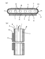
- FIG. 1 shows a solid oxide fuel cell, where (a) is a cross-sectional view and (b) is a vertical cross-sectional view.
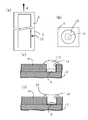
- (A) is a side view of the solid oxide fuel cell of FIG. 1
- (b) is an enlarged plan view showing a portion of the sealing material and its vicinity, and (c) is present in the solid electrolyte layer of (a).
- Sectional drawing which expanded a part of the state which block
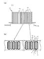
- FIG. 1 shows an embodiment of a fuel cell stack device
- (a) is a side view schematically showing the fuel cell stack device
- (b) is a part of a portion surrounded by a broken line of the fuel cell stack device of (a).
- FIG. It is a partial cross section figure of the fuel cell stack apparatus of FIG. It is an external appearance perspective view which shows one form of a fuel cell module. It is a disassembled perspective view which shows one form of a fuel cell apparatus.
- a flat fuel cell is shown, in which (a) is a sectional view and (b) is a side view.
- FIG. 8 is a cross-sectional view taken along line xx of FIG.
- FIG. 1 shows one embodiment of a solid oxide fuel cell of the present invention (hereinafter sometimes abbreviated as a fuel cell), (a) is a cross-sectional view thereof, and (b) is (a) FIG. In both drawings, each configuration of the fuel cell 10 is partially enlarged.
- a fuel cell solid oxide fuel cell of the present invention
- This fuel cell 10 is a hollow plate type fuel cell 10 having a flat cross section and a porous conductive support (hereinafter referred to as a support) containing Ni having an elliptical cylindrical shape as a whole. 1) is provided inside the conductive support 1, a plurality of fuel gas passages 2 are formed penetrating in the longitudinal direction at appropriate intervals.
- the fuel cell 10 is formed on the conductive support 1 with various members. Has a structure provided.
- the conductive support 1 has a pair of flat surfaces n parallel to each other and arcuate surfaces (side surfaces) m connecting the pair of flat surfaces n. It consists of and. Both surfaces of the flat surface n are formed substantially parallel to each other, and the porous fuel electrode layer 3 is provided so as to cover the flat surface n (lower surface) on one side and the arcuate surfaces m on both sides. Further, a dense solid electrolyte layer 4 is disposed so as to cover the fuel electrode layer 3.
- a porous oxygen electrode layer 6 is disposed on the solid electrolyte layer 4 so as to face the fuel electrode layer 3.
- An interconnector 8 is disposed on the other flat surface n (upper surface) on which the fuel electrode layer 3 and the solid electrolyte layer 4 are not disposed via an intermediate layer 7.
- the interconnector 8 and the solid electrolyte layer 4 form a cylindrical body, and the conductive support 1 and the fuel electrode layer 6 are formed inside the cylindrical body.
- the conductive support 1 is formed so as to penetrate through the cylindrical body in the opening direction (longitudinal direction of the conductive support 1).
- the power generating element portion 9 in which the fuel electrode layer 3 and the oxygen electrode layer 6 are formed on both sides of the solid electrolyte layer 4 is provided on the flat surface on one side of the conductive support 1, and the flat surface on the other side.
- An intermediate layer 7 and an interconnector 8 are formed on the surface.
- the interconnector 8 is electrically connected to the fuel electrode layer 3 of the power generation element portion 9 formed on the flat surface on one side of the conductive support 1 via the intermediate layer 7 and the conductive support 1. Yes.
- the fuel electrode layer 3 and the solid electrolyte layer 4 are formed to the other flat surface n (upper surface) via the arcuate surfaces m at both ends of the conductive support 1, and the interconnector 8 is connected to both ends of the solid electrolyte layer 4.
- the solid support layer 1 and the interconnector 8 surround the conductive support 1 so that the fuel gas flowing inside does not leak to the outside.
- the hole 14 which exists in the thickness direction of the solid electrolyte layer 4 is plugged with the sealing material 15. That is, a hole 14 penetrating in the thickness direction is generated in the solid electrolyte layer 4.
- the holes 14 are generated by, for example, dust attached to the green sheet before firing, aggregated powder of raw materials, poor formation of the green sheet, or the like.
- the holes 14 are not only formed in the thickness direction of the solid electrolyte layer 4 as shown in FIG. 2C, but also may be formed obliquely with a certain angle with respect to the thickness direction. As shown in (c), not only a hole that connects the main surfaces of the solid electrolyte layer 4 but also one main surface and the end surface (side surface) of the solid electrolyte layer 4 may be connected. is there. Furthermore, the hole 14 is not only formed in a straight line as shown in FIG. 2C, but also formed in a bent shape. Although not shown in FIG. 2, holes are also generated in the interconnector 8 as in the case of the solid electrolyte layer 4 due to the above cause.
- the holes 14 are more easily formed as the thickness of the solid electrolyte layer 4 is reduced in order to improve the power generation performance. It was necessary to strictly manage the management and manufacturing process. Similarly, as the thickness of the interconnector 8 is reduced, the electrical conductivity is improved. Therefore, the thinner the interconnector 8 is, the easier the hole 14 is formed. It was necessary to strictly manage the raw material management and manufacturing process of the connector 8.
- the average diameters of the holes 14 of the solid electrolyte layer 4 and the interconnector 8 are each 1 mm or less, particularly 10 ⁇ m to 1 mm, and further 50 ⁇ m to 500 ⁇ m.
- the average diameter of the hole 14 can be obtained from a scanning electron microscope (SEM) photograph of the hole 14 portion.
- SEM scanning electron microscope
- the manufacturing conditions are set slightly wider, and the holes 14 penetrating in the thickness direction are generated in the solid electrolyte layer 4.
- the sealing material 15 by closing the hole 14 with the sealing material 15, it is possible to ensure the densification of the solid electrolyte layer 4 and to easily prevent the fuel gas from leaking to the outside. Therefore, labor, time and cost in manufacturing can be reduced. The same applies to the holes generated in the interconnector 8.
- the sealing material 15 is preferably made of glass.
- the sealing material 15 is glass, the fluidity during heat treatment is high, and the holes 14 can be sealed at a low temperature.
- the glass Ba series, Si series, B series and the like can be used.
- a crystallized glass that crystallizes after heat treatment is desirable. This is because the crystallized glass does not grow the particles constituting the fuel electrode layer 3 more than the amorphous glass.
- the sealing material 15 for closing the holes 14 generated in the solid electrolyte layer 4 and the interconnector 8 is a seal for closing the material forming each layer in which the holes 14 are generated, for example, the holes 14 formed in the solid electrolyte layer 4.
- the material 15 can be a solid electrolyte material. Thereby, the solid electrolyte layer 4 and the interconnector 8 around the sealing material 15 are not affected.
- the interconnector material and the solid electrolyte material as the sealing material 15 can be fired at a temperature lower than the firing temperature.
- FIGS. 2B and 2C when the sealing material 15 is made of glass, the sealing material 15 is inside the hole 14 of the solid electrolyte layer 4 and the solid electrolyte layer around the hole 14. It is desirable that a space S is formed between the fuel electrode layer 3 and the sealing material 15 as well as existing on the surface. Thereby, the sealing material 15 and the fuel electrode layer 3 are not in direct contact, and the particles constituting the fuel electrode layer 3 are not grown.
- 2A is a side view seen from the left side toward the paper surface of FIG. 1B.
- the upper surface of the sealing material 15 is desirably flat or recessed as shown in FIG. 2D shows a state in which the upper surface of the sealing material 15 is recessed. That is, the sealing material 15 protrudes from the surface of the solid electrolyte layer 4 and the interconnector 8, and the top portion is flat or recessed. Thereby, the unevenness
- the support 1 is required to be gas permeable to allow the fuel gas to permeate to the fuel electrode layer 3 and to be conductive to collect current via the interconnector 8.
- the support 1 is preferably composed of an iron group metal component and a specific rare earth oxide.
- the conductive material is not limited to this.
- the iron group metal component is for imparting conductivity to the support 1, and may be a single iron group metal, or an iron group metal oxide, an iron group metal alloy or an alloy oxide. May be.
- the iron group metals include Fe, Ni, and Co. In the present embodiment, any of them can be used, but Ni and / or NiO is an iron group because it is inexpensive and stable in fuel gas. It is preferable to contain as a metal component.
- the rare earth oxide component is used to approximate the thermal expansion coefficient of the support 1 to the thermal expansion coefficient of the solid electrolyte layer 4.
- at least one selected from the group consisting of Y, Lu, Yb, Tm, Er, Ho, Dy, Gd, Sm, and Pr It is preferable to use a rare earth oxide containing a rare earth element in combination with the iron group metal component.
- Such rare earth oxides include Y 2 O 3 , Lu 2 O 3 , Yb 2 O 3 , Tm 2 O 3 , Er 2 O 3 , Ho 2 O 3 , Dy 2 O 3 , Gd 2 O 3 , Sm 2 O. 3 and Pr 2 O 3 can be exemplified, and Y 2 O 3 and Yb 2 O 3 are preferable in that they are particularly inexpensive.
- rare earth oxides hardly cause solid solution or reaction with the iron group metal or its oxide during firing or during power generation, and the iron group metal or its oxide in the support 1, and Any of the rare earth oxides is difficult to diffuse. Therefore, even when the support 1 and the solid electrolyte layer 4 are co-fired, the diffusion of rare earth elements into the solid electrolyte layer 4 is reduced, and adverse effects on the ionic conductivity and the like of the solid electrolyte layer 4 are avoided. Can do.
- the iron group metal component is contained in the support 1 in an amount of 35 to 70% by volume in that the thermal expansion coefficient of the support 1 is approximated to the thermal expansion coefficient of the solid electrolyte layer 4.
- the rare earth oxide is preferably contained in the support 1 in an amount of 30 to 65% by volume.
- the support 1 may contain other metal components and oxide components as long as required characteristics are not impaired.
- the open porosity is usually 30% or more, particularly 35. It is preferable to be in the range of ⁇ 50%.
- the conductivity of the support 1 is preferably 300 S / cm or more, and particularly preferably 440 S / cm or more.
- the length of the flat surface n of the support 1 is usually 15 to 35 mm, and the height of the support 1 is appropriately set according to the application, but is used for power generation in a general household. In some cases, the height is usually set to about 100 to 200 mm.
- arc-shaped surfaces m are formed at both ends of the flat surface n in order to prevent chipping at the corners and further increase the mechanical strength.
- the thickness of the support 1 is desirably in the range of 2 to 10 mm.
- the fuel electrode layer 3 causes an electrode reaction, and is formed of a known porous cermet.
- a porous cermet For example, it is formed from ZrO 2 or CeO 2 in which a rare earth element is dissolved, and Ni and / or NiO.
- the ZrO 2 or CeO 2 content in the fuel electrode layer 3 is preferably in the range of 35 to 65% by volume, and the Ni or NiO content is preferably 65 to 35% by volume. Further, the open porosity of the fuel electrode layer 3 should be 15% or more, particularly in the range of 20 to 40%.
- the thickness of the anode layer 3 is 1 to 30 ⁇ m is desirable.
- the rare earth element solid-dissolved in ZrO 2 or CeO 2 (in the case of CeO 2 , a rare earth element other than Ce) is the same as that shown for the rare earth oxide used in the support 1.
- Y is about 3 to 10 mol% with respect to ZrO 2
- Sm is about 5 to 20 mol% with respect to CeO 2 in terms of reducing the polarization value of the cell.
- Y is about 3 to 10 mol% with respect to ZrO 2
- Sm is about 5 to 20 mol% with respect to CeO 2 in terms of reducing the polarization value of the cell.
- the fuel electrode layer 3 exists at least at a position facing the oxygen electrode layer 6. That is, in the example of FIG. 1, the fuel electrode layer 3 extends from the flat surface n on one side of the support 1 to the other flat surface n and extends to both ends of the interconnector 8, but is flat on one side. It may be formed only on the surface n.
- a diffusion suppression layer may be provided on the fuel electrode layer 3 and the diffusion suppression layer may be interposed between the fuel electrode layer 3 and the solid electrolyte layer 4. .
- This diffusion suppression layer is for suppressing element diffusion from the fuel electrode layer 3 or the support 1 to the solid electrolyte layer 4 and avoiding performance degradation due to the formation of the insulating layer.
- La 2 O 3 in which Ce is dissolved, or a mixture thereof may be contained in this diffusion preventing layer. Examples of the rare earth element include Sc, Y, Pr, Nd, Pm, Sm, Eu, Gd, Tb, Dy, Ho, Er, Tm, Yb, and Lu.
- such a diffusion suppressing layer extends to both ends of the interconnector 8 together with the solid electrolyte layer 4. This is because element diffusion from the support 1 or the fuel electrode layer 3 to the solid electrolyte layer 4 can be further prevented.
- Solid electrolyte layer 4 has a function as an electrolyte for bridging electrons between the electrodes, and at the same time has gas barrier properties to prevent leakage of fuel gas and oxygen-containing gas such as air. is necessary. Therefore, as a material used for forming the solid electrolyte layer 4, a dense oxide ceramic having such characteristics, for example, stabilized zirconia (ZrO 2 in which 3 to 15 mol% of a rare earth element is dissolved) is used. ) Is preferably used.
- rare earth elements in the stabilized zirconia include Sc, Y, La, Ce, Pr, Nd, Pm, Sm, Eu, Gd, Td, Dy, Ho, Er, Tm, Yb, and Lu.
- Y and Yb are preferable in that they are inexpensive.
- a perovskite-type lanthanum gallate complex oxide containing La and Ga can also be used as the solid electrolyte.
- This composite oxide has high oxygen ion conductivity, and high power generation efficiency can be obtained by using it as a solid electrolyte.
- This lanthanum gallate composite oxide has La and Sr at the A site and Ga and Mg at the B site.
- the following general formula (La 1-x Sr x ) (Ga 1-y Mg y ) O 3 wherein x is a number 0 ⁇ x ⁇ 0.3 and y is a number 0 ⁇ y ⁇ 0.3.
- High power generation performance can also be exhibited by using a composite oxide having such a composition as a solid electrolyte.
- Such a solid electrolyte layer 4 desirably has a relative density (according to Archimedes method) of 93% or more, particularly 95% or more from the viewpoint of preventing gas permeation.
- the average thickness of the solid electrolyte layer 4 is preferably 5 to 40 ⁇ m in order to improve the power generation performance.
- the average thickness of the solid electrolyte layer 4 is made as thin as 5 to 20 ⁇ m in order to improve the power generation performance, holes are easily formed, and thus the above embodiment can be suitably used.
- the oxygen electrode layer 6 formed on the solid electrolyte layer 4 causes the electrode reaction described above, and as shown in FIG. 1, the fuel electrode layer described above with the solid electrolyte layer 4 interposed therebetween. 3 is arranged so as to face 3. That is, it is arranged at least on a portion located on one flat surface n of the support 1.
- the oxygen electrode layer 6 is formed of sintered particles of a so-called ABO 3 type perovskite oxide.
- ABO 3 type perovskite oxide at least one of transition metal type perovskite oxides, particularly LaMnO 3 oxides, LaFeO 3 oxides, LaCoO 3 oxides having La at the A site is preferable, and 600 (La, Sr) (Co, Fe) O 3 system from the viewpoint of high electrical conductivity at a relatively low temperature of about 1000 ° C. and excellent surface diffusion function and volume diffusion function with respect to oxygen ions.
- La-Sr-Co-based composite oxides for example, the following general formula: La y Sr 1-y Co Z Fe 1-Z O 3 (wherein y is 0.5
- a composite oxide having a composition represented by: ⁇ y ⁇ 0.7 and z is a number satisfying 0.2 ⁇ z ⁇ 0.8 is particularly preferable.
- an oxygen electrode layer 6 must have gas permeability. Therefore, the above-mentioned conductive ceramics should have an open porosity of 20% or more, particularly 30 to 50%. Is desirable.
- the thickness of the oxygen electrode layer 6 is preferably 30 to 100 ⁇ m from the viewpoint of current collection.
- the oxygen electrode layer 6 may be formed on the solid electrolyte layer 4, although not shown in the drawing, a reaction preventing layer is provided on the solid electrolyte layer 4 as necessary, and such a reaction is performed.
- the oxygen electrode layer 6 can also be laminated on the solid electrolyte layer 4 via the prevention layer.
- Such a reaction preventing layer is for blocking element diffusion from the oxygen electrode layer 6 to the solid electrolyte layer 4, and is formed of an oxide sintered body having an element diffusion preventing function.
- an oxide for a reaction preventing layer for example, an oxide containing Ce as a constituent element can be exemplified, and in particular, a Ce-based composite oxide in which a rare earth element oxide other than Ce is dissolved in CeO 2 . However, it is preferably used in that it has excellent oxygen ion conductivity and electron conductivity in addition to high element diffusion barrier properties.
- the interconnector 8 provided on the flat surface n on the support 1 is made of conductive ceramics, but has contact with fuel gas (hydrogen) and oxygen-containing gas, and therefore has resistance to reduction and oxidation. It is necessary to be. For this reason, lanthanum chromite perovskite oxides (LaCrO 3 oxides) are generally used as the conductive ceramics.
- the interconnector 8 may be a perovskite complex oxide containing Ti, such as a perovskite complex oxide containing La, Sr and Ti, and is not particularly limited.
- the conductive ceramics in order to prevent leakage of the fuel gas passing through the inside of the support 1 and the oxygen-containing gas passing through the outside of the support 1, the conductive ceramics must be dense, for example, 93% or more, particularly 95%. It is preferable to have the above relative density.
- the average thickness of the interconnector 8 is preferably 10 to 200 ⁇ m from the viewpoint of preventing gas leakage and electric resistance.
- the hole 14 is easily formed when the average thickness is as thin as 10 to 40 ⁇ m. Therefore, this embodiment is preferably used. be able to.
- the fuel battery cell having the above-described structure can be manufactured by a known method, but it is particularly preferable to use the co-firing method described below. The following manufacturing method is described by taking the fuel cell having the structure shown in FIGS.
- the mixed powder for forming the conductive support 1 described above is mixed with an organic binder, a solvent, and, if necessary, a dispersant to prepare a clay, and the clay is extruded to obtain a fuel.
- a columnar molded body for a conductive support having a gas flow path is prepared, dried, and calcined in a temperature range of 800 to 1100 ° C.
- the mixed powder used for producing the conductive support molded body is, for example, a mixture of iron group metal or iron group metal oxide powder and rare earth oxide powder in a predetermined volume ratio. .
- a sheet for a solid electrolyte layer (hereinafter referred to as a solid electrolyte layer sheet) is prepared. That is, for example, a solid electrolyte powder such as ZrO 2 (YSZ) containing Y is mixed with an organic binder and a solvent to prepare a slurry, and using this slurry, a sheet for a solid electrolyte layer is prepared by a doctor blade method or the like. Mold.
- YSZ ZrO 2
- a fuel electrode layer sheet is produced by a doctor blade method or the like using a slurry prepared by mixing an organic binder and a solvent with a fuel electrode layer forming powder (for example, a mixed powder of NiO powder and YSZ powder).
- a fuel electrode layer forming powder for example, a mixed powder of NiO powder and YSZ powder.
- the fuel electrode layer sheet is laminated on one surface of the solid electrolyte layer sheet, and the fuel electrode layer sheet is placed at a predetermined position on the above-mentioned support molded body (calcined body). Wrap and dry.
- a powder for an interconnector such as a LaCrO 3 based material is mixed with an organic binder and a solvent to prepare a slurry, and a sheet for the interconnector is produced by using the slurry by a doctor blade method or the like.
- an intermediate layer sheet is produced by a doctor blade method or the like, The intermediate layer sheet is laminated on one surface of the interconnector sheet.
- the interconnector sheet on which the intermediate layer sheet is laminated is placed on the surface of the conductive support molded body on which the solid electrolyte layer sheet is not laminated so that the intermediate layer sheet side is on the conductive support molded body side. Laminate and dry.
- the laminated molded body is subjected to a heat treatment for debinding, and then co-fired at 1300 to 1600 ° C. in an oxygen-containing atmosphere such as the air, whereby the fuel electrode layer 3 is formed on the conductive support 1.
- the solid electrolyte layer 4 is laminated, and the intermediate layer 7 and the interconnector 8 are further laminated at predetermined positions. If necessary, a sintered body having an element diffusion preventing layer and a reaction preventing layer can be obtained.
- a gas leak test is performed. This is because the sintered body is immersed in water in a state where one side of the fuel gas passage 2 is closed, and a gas, for example, He gas, is given to the other side of the fuel gas passage 2 of the conductive support 1 in a predetermined manner. Supply is performed under pressure, for example, 3 kg / cm 2 , and whether or not holes 14 are generated in the solid electrolyte layer 4 and the interconnector 8 is confirmed by whether or not bubbles are generated.
- a gas for example, He gas
- the portion where the bubbles are generated is marked, and after the sintered body is dried, for example, a glass material made of Ba, Si, Zr, Al or the like and an organic material are mixed.
- a glass paste is applied in the vicinity of the hole 14 and injected into the hole 14. Formation of the space S as shown in FIG. 2C can be achieved by setting the viscosity of the glass paste high. Thereafter, heat treatment is performed at a temperature lower than the temperature at the time of the co-firing.
- the heat treatment temperature and heat treatment time of the glass paste depend on the glass material used, for example, it is 1000 to 1300 ° C., and the heat treatment time is 0.5 to 10 hours.
- the top of the sealing material 15 may be flattened or recessed as shown in FIG. 2D by controlling the material of the sealing material 15 in the hole 14, the heat treatment temperature, the treatment time, and the like. In this case, even when the oxygen electrode layer 6 is formed on the upper surface of the sealing material 15, the rise of the oxygen electrode layer 6 on the upper surface of the sealing material 15 can be reduced.
- a material having a softening point lower than that of the glass glass material shown in FIG. 2C is used, the heat treatment temperature is increased, or the heat treatment time is lengthened.
- an oxygen electrode layer coating solution in which LaFeO 3 oxide powder or the like is dispersed in a solvent is sprayed (or dip coated).
- a fuel cell having the oxygen electrode layer 6 can be obtained by forming a coating layer for the oxygen electrode layer and baking it at 1000 to 1300 ° C.
- the conductor component contained in the support 1 or the like is an oxide such as NiO by firing in an oxygen-containing atmosphere. Such an oxide supplies a fuel gas. It will be reduced by the reduction process and power generation.
- the hole 14 is formed in the solid electrolyte layer 4 and the interconnector 8, and the hole 14 is closed with the sealing material 15.
- the holes 14 may be formed on either side.
- FIG. 3 shows an embodiment of a fuel cell stack device configured by electrically connecting a plurality of the above-described fuel cells 10 in series via a current collecting member 13.
- (b) is a partially enlarged sectional view of the fuel cell stack device 11 of (a), and is a part surrounded by a broken line shown in (a)
- the excerpt is shown.
- (b) in order to clarify, the part corresponding to the part enclosed with the broken line shown by (a) is shown with the arrow.
- each fuel cell 10 is arranged via a current collecting member 13, and the fuel cell 10 and the current collecting member 13 are joined by a conductive adhesive.
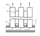
- the lower end portion of each fuel battery cell 10 is joined to the upper wall of a gas tank 16 made of a heat-resistant alloy for supplying fuel gas to the fuel battery cell 10. It is fixed by a material 17. That is, the upper wall of the gas tank 16 is formed with a through hole into which the lower end of the cell stack 12 is inserted. With the lower end of the cell stack 12 inserted into the through hole, glass, glass ceramics, etc. Bonded with a bonding material 17.
- the fuel cell stack device 11 of this embodiment the fuel cell stack device 11 having improved long-term reliability is obtained by configuring the fuel cell stack 12 using the fuel cell 10 described above. be able to.
- FIG. 5 is an external perspective view showing an embodiment of the fuel cell module 18 in which the fuel cell stack device 11 is accommodated in the storage container 19.
- the fuel cell module 18 is shown in FIG. 3 inside the rectangular parallelepiped storage container 19.
- the fuel cell stack device 11 is accommodated.
- a reformer 20 for reforming raw fuel such as natural gas or kerosene to generate fuel gas is provided above the fuel cell stack 12 in order to obtain fuel gas used in the fuel cell 10. It is arranged.
- the fuel gas generated by the reformer 20 is supplied to the gas tank 16 via the gas flow pipe 21 and supplied to the fuel gas passage 2 provided inside the fuel cell 10 via the gas tank 16.
- FIG. 5 shows a state in which a part (front and rear surfaces) of the storage container 19 is removed and the fuel cell stack device 11 and the reformer 20 housed inside are taken out rearward.
- the fuel cell stack device 11 can be slid and stored in the storage container 19.
- the fuel cell stack device 11 may include the reformer 20.
- the oxygen-containing gas introduction member 22 provided inside the storage container 19 is disposed between the fuel cell stacks 12 juxtaposed to the gas tank 16, and the oxygen-containing gas flows into the flow of the fuel gas.
- oxygen-containing gas is supplied to the lower end portion of the fuel cell 10 so that the side of the fuel cell 10 flows from the lower end portion toward the upper end portion.
- the temperature of the fuel cell 10 is raised by reacting the fuel gas discharged from the fuel gas channel 2 of the fuel cell 10 with the oxygen-containing gas and burning it on the upper end side of the fuel cell 10.
- the start-up of the fuel cell stack device 11 can be accelerated.
- the fuel battery cell 10 (fuel battery cell stack 12) is burned. ) Can be warmed. Thereby, the reforming reaction can be efficiently performed in the reformer 20.
- the fuel cell module 18 of this embodiment since the fuel cell stack device 11 described above is housed in the housing container 19, the fuel cell module 18 with improved long-term reliability can be obtained.
- FIG. 6 is an exploded perspective view showing an embodiment of a fuel cell device in which the fuel cell module 18 shown in FIG. 5 and an auxiliary machine for operating the fuel cell stack device 11 are housed in an outer case. It is. In FIG. 6, a part of the configuration is omitted.
- a fuel cell device 23 shown in FIG. 6 has a module housing chamber in which an outer case made up of support columns 24 and an outer plate 25 is divided into upper and lower portions by a partition plate 26 and the upper side thereof stores the above-described fuel cell module 18. 27, the lower side is configured as an auxiliary equipment storage chamber 28 for storing auxiliary equipment for operating the fuel cell module 18.
- the auxiliary machine stored in the auxiliary machine storage chamber 28 is omitted.
- the auxiliary machine includes at least a blower for supplying oxygen-containing gas and a pump for supplying fuel gas.
- the partition plate 26 is provided with an air circulation port 29 for flowing the air in the auxiliary machine storage chamber 28 to the module storage chamber 27 side, and a part of the exterior plate 25 constituting the module storage chamber 27 An exhaust port 30 for exhausting the air in the module storage chamber 27 is provided.
- the fuel cell module 18 that can improve the reliability is housed in the module housing chamber 27, thereby improving the reliability. 23.
- the hollow plate type solid oxide fuel cell has been described, but it is needless to say that it may be a cylindrical or flat plate type solid oxide fuel cell.
- a power generation element portion in which a fuel electrode layer, a solid electrolyte layer, and an oxygen electrode layer are sequentially provided, a fuel-side current collector that is electrically connected to the fuel electrode layer, and an oxygen side that is electrically connected to the oxygen electrode layer
- a plurality of flat plate type fuel cells having a current collector are stacked via an interconnector, and a fuel gas and an oxygen-containing gas are supplied to the central portions of the fuel electrode layer and the oxygen electrode layer, respectively.
- the present invention can also be applied to a cell stack apparatus of a type in which gas flows toward the outer periphery of the fuel electrode layer and the oxygen electrode layer, and excess fuel gas and oxygen-containing gas are released from the outer periphery of the fuel cell.
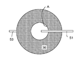
- a power generation element portion 33 in which a fuel electrode layer 33a, a solid electrolyte layer 33b, and an oxygen electrode layer 33c are sequentially provided, and a fuel-side current collector that is electrically connected to the fuel electrode layer 33a.
- the present invention can also be applied to a cell stack device in which a plurality of fuel cells each including a body 36 and an oxygen-side current collector 35 electrically connected to the oxygen electrode layer 33c are stacked via interconnectors 37 and 38.
- reference numeral 51 denotes a fuel gas supply pipe
- reference numeral 53 denotes an oxygen-containing gas supply pipe.
- NiO powder having an average particle size of 0.5 ⁇ m and Y 2 O 3 powder having an average particle size of 0.9 ⁇ m are mixed, and a clay prepared by mixing an organic binder and a solvent is formed by an extrusion molding method. Drying and degreasing were performed to produce a molded article for a conductive support.
- a solid electrolyte layer sheet was prepared by a blade method.
- a fuel electrode layer slurry is prepared by mixing a NiO powder having an average particle size of 0.5 ⁇ m, a ZrO 2 powder (YSZ powder) in which Y 2 O 3 is dissolved, an organic binder, and a solvent.
- a fuel electrode layer sheet was prepared using the slurry. This fuel electrode layer sheet was laminated on the solid electrolyte layer sheet.
- a sheet-shaped laminate formed by laminating a sheet for a fuel electrode layer on a sheet for a solid electrolyte layer is laminated at a predetermined position of the molded body for a conductive support with the surface on the sheet side for the fuel electrode layer facing inward.
- the molded body was calcined at 1000 ° C. for 3 hours.
- An intermediate layer slurry was prepared by mixing an organic binder and a solvent with a raw material composed of NiO powder and YSZ powder.
- An intermediate layer sheet is prepared using the adjusted intermediate layer slurry, and a portion of the molded body for the conductive support where the fuel electrode layer sheet (and the solid electrolyte layer sheet) is not formed (for the conductive support) Then, the interconnector sheet was laminated on the intermediate layer sheet.
- the above-mentioned laminated molded body was debindered and co-fired at 1450 ° C. for 2 hours in an oxygen-containing atmosphere.
- the size of the produced fuel cell 10 is 25 mm wide ⁇ 200 mm long, the thickness of the conductive support 1 (average thickness between the flat surfaces n) is 2 mm, the open porosity is 35%, and the average thickness of the fuel electrode layer.
- the thickness was 10 ⁇ m, the open porosity was 24%, the average thickness of the solid electrolyte layer 8 was 10 ⁇ m, and the average thickness of the interconnector was 10 ⁇ m.
- another fuel cell 10 having an average thickness of the solid electrolyte layer 4 of 20 ⁇ m and an average thickness of the interconnector 8 of 40 ⁇ m was produced.
- the average thickness of the solid electrolyte layer 4 was obtained by obtaining the thickness of the solid electrolyte layer 4 in the flat portion of the conductive support 1 from three cross-sectional photographs of a scanning electron microscope (SEM) and averaging them.
- the average thickness of the interconnector 8 was determined in the same manner.
- the presence or absence of the holes 14 of the solid electrolyte layer 4 and the interconnector 8 was confirmed by a leak test.
- a leak test a fuel cell 10 in which one side of the fuel gas channel 2 is sealed by a predetermined member is placed in water, and the fuel gas channel 2 on the other side of the fuel cell 10 is set to 3 kg / cm 2 .
- pressurized He gas is supplied, and a hole is formed in a portion where bubbles are generated from the fuel cell 10.
- both the solid electrolyte layer 4 and the interconnector 8 were in the range of 100 to 500 ⁇ m.
- the average diameter of the hole 14 is obtained by obtaining the hole area with an image analysis apparatus for a 10,000 times SEM photograph of the portion where the hole 14 is present, determining the hole shape as a circle, and determining the diameter from the hole area. It was.
- a silica-based crystallized glass material, an organic binder, and a solvent are mixed into the hole 14 to prepare a sealing material paste, and this paste is injected into the hole 14 using a discharge device (dispenser). Heat treatment was performed at 1150 ° C. for 1 hour, and the holes 14 were closed with the sealing material 15.
- the oxygen electrode layer formed body was formed by spray coating, and baked at 1100 ° C. for 4 hours to form the oxygen electrode layer 6.
- the oxygen electrode layer 6 had a thickness of 50 ⁇ m and an open porosity of 40%.
- conductive support 2 fuel gas flow path 3: fuel electrode layer 4: solid electrolyte layer 6: oxygen electrode layers 8, 37, 38: interconnector 9, 33: power generation element unit 10: solid oxide fuel cell Cell 11: Fuel cell stack device 14: Hole 15: Seal material 18: Fuel cell module 23: Fuel cell device
Landscapes
- Engineering & Computer Science (AREA)
- Chemical & Material Sciences (AREA)
- Manufacturing & Machinery (AREA)
- Chemical Kinetics & Catalysis (AREA)
- Sustainable Energy (AREA)
- Sustainable Development (AREA)
- Life Sciences & Earth Sciences (AREA)
- Electrochemistry (AREA)
- General Chemical & Material Sciences (AREA)
- Inorganic Chemistry (AREA)
- Materials Engineering (AREA)
- Ceramic Engineering (AREA)
- Fuel Cell (AREA)
Abstract
La présente invention vise à proposer : une pile à combustible à oxyde solide qui est apte à empêcher de manière aisée une fuite de gaz ; un système d'empilement de piles à combustible ; un module de piles à combustibles ; et un système de piles à combustibles. A cet effet, est proposée une pile à combustible à oxyde solide (10) qui comprend une unité d'élément de génération d'énergie électrique (9) qui est configurée par la prise en sandwich d'une couche d'électrolyte solide (4) entre une coche d'électrode à combustible (30) et une couche d'électrode à oxygène (6), et un orifice (14) qui est présent dans la couche d'électrolyte solide (4) étant recouvert d'un matériau de scellement (15). De plus, un orifice (14) qui est présent dans un interconnecteur (8), qui est connecté électriquement à la couche d'électrode à combustible (3) ou à la couche d'électrode à oxygène (6), est recouvert du matériau de scellement (15). En conséquence, la pile combustible à oxyde solide (10) est apte à empêcher de manière aisée une fuite de gaz.
Priority Applications (4)
| Application Number | Priority Date | Filing Date | Title |
|---|---|---|---|
| JP2012540617A JP5197890B2 (ja) | 2011-05-30 | 2012-05-29 | 固体酸化物形燃料電池セルおよび燃料電池セルスタック装置ならびに燃料電池モジュール、燃料電池装置 |
| EP12793143.4A EP2717368B1 (fr) | 2011-05-30 | 2012-05-29 | Pile à combustible à oxyde solide, système d'empilement de piles à combustibles, module de piles à combustibles et système de piles à combustible |
| US14/119,767 US9627697B2 (en) | 2011-05-30 | 2012-05-29 | Solid oxide fuel cell, fuel cell stack system, fuel cell module, and fuel cell system |
| US15/455,171 US10367220B2 (en) | 2011-05-30 | 2017-03-10 | Solid oxide fuel cell, fuel cell stack device, fuel cell module, and fuel cell apparatus |
Applications Claiming Priority (2)
| Application Number | Priority Date | Filing Date | Title |
|---|---|---|---|
| JP2011-120649 | 2011-05-30 | ||
| JP2011120649 | 2011-05-30 |
Related Child Applications (2)
| Application Number | Title | Priority Date | Filing Date |
|---|---|---|---|
| US14/119,767 A-371-Of-International US9627697B2 (en) | 2011-05-30 | 2012-05-29 | Solid oxide fuel cell, fuel cell stack system, fuel cell module, and fuel cell system |
| US15/455,171 Continuation US10367220B2 (en) | 2011-05-30 | 2017-03-10 | Solid oxide fuel cell, fuel cell stack device, fuel cell module, and fuel cell apparatus |
Publications (1)
| Publication Number | Publication Date |
|---|---|
| WO2012165409A1 true WO2012165409A1 (fr) | 2012-12-06 |
Family
ID=47259263
Family Applications (1)
| Application Number | Title | Priority Date | Filing Date |
|---|---|---|---|
| PCT/JP2012/063716 Ceased WO2012165409A1 (fr) | 2011-05-30 | 2012-05-29 | Pile à combustible à oxyde solide, système d'empilement de piles à combustibles, module de piles à combustibles et système de piles à combustible |
Country Status (4)
| Country | Link |
|---|---|
| US (2) | US9627697B2 (fr) |
| EP (1) | EP2717368B1 (fr) |
| JP (2) | JP5197890B2 (fr) |
| WO (1) | WO2012165409A1 (fr) |
Cited By (8)
| Publication number | Priority date | Publication date | Assignee | Title |
|---|---|---|---|---|
| JP2017098027A (ja) * | 2015-11-20 | 2017-06-01 | 京セラ株式会社 | セル、セルスタック装置、モジュール、およびモジュール収容装置 |
| JP2017112045A (ja) * | 2015-12-18 | 2017-06-22 | 京セラ株式会社 | セルスタック装置、モジュールおよびモジュール収容装置 |
| WO2018029935A1 (fr) | 2016-08-09 | 2018-02-15 | 日本特殊陶業株式会社 | Cellule de réaction électrochimique individuelle, et empilement de cellules de réaction électrochimique |
| WO2018097174A1 (fr) | 2016-11-22 | 2018-05-31 | 日本特殊陶業株式会社 | Unité de réaction électrochimique, empilement de cellules de réaction électrochimique, et procédé de production d'unité de réaction électrochimique |
| WO2018151193A1 (fr) | 2017-02-16 | 2018-08-23 | 日本特殊陶業株式会社 | Cellule unique à réaction électrochimique et assemblage de cellules à réaction électrochimique |
| WO2018150664A1 (fr) | 2017-02-16 | 2018-08-23 | 日本特殊陶業株式会社 | Cellule de réaction électrochimique individuelle et empilement de cellules de réaction électrochimique |
| WO2018155111A1 (fr) | 2017-02-27 | 2018-08-30 | 日本特殊陶業株式会社 | Unité de réaction électrochimique, empilement de cellules de réaction électrochimique, et procédé de production pour unité de réaction électrochimique |
| WO2018155112A1 (fr) | 2017-02-27 | 2018-08-30 | 日本特殊陶業株式会社 | Unité de réaction électrochimique et empilement de cellules de réaction électrochimique |
Families Citing this family (8)
| Publication number | Priority date | Publication date | Assignee | Title |
|---|---|---|---|---|
| US6368343B1 (en) | 2000-03-13 | 2002-04-09 | Peter M. Bonutti | Method of using ultrasonic vibration to secure body tissue |
| JP6460316B2 (ja) * | 2013-12-09 | 2019-01-30 | 日本電気硝子株式会社 | ナトリウムイオン電池用電極合材、及びその製造方法並びにナトリウム全固体電池 |
| JP6401115B2 (ja) * | 2015-05-27 | 2018-10-03 | 京セラ株式会社 | セルスタック装置、モジュールおよびモジュール収容装置 |
| WO2018042477A1 (fr) * | 2016-08-29 | 2018-03-08 | FCO Power株式会社 | Interconnecteur, empilement de piles à combustible à oxyde solide, et procédé de fabrication d'empilement de piles à combustible à oxyde solide |
| WO2018042476A1 (fr) * | 2016-08-29 | 2018-03-08 | FCO Power株式会社 | Inter-connecteur, empilement de piles à combustible à oxyde solide, et procédé de fabrication d'empilement de piles à combustible à oxyde solide |
| JP6957736B2 (ja) * | 2018-03-28 | 2021-11-02 | 京セラ株式会社 | セルスタック装置、モジュールおよびモジュール収容装置 |
| US20230327162A1 (en) * | 2020-08-24 | 2023-10-12 | Kyocera Corporation | Cell, cell stack device, module, and module housing device |
| JP2022120964A (ja) * | 2021-02-08 | 2022-08-19 | 本田技研工業株式会社 | 燃料電池スタックの漏洩試験方法 |
Citations (8)
| Publication number | Priority date | Publication date | Assignee | Title |
|---|---|---|---|---|
| JPH0652869A (ja) * | 1992-07-30 | 1994-02-25 | Nippon Telegr & Teleph Corp <Ntt> | 燃料電池の固体電解質膜およびその製造方法 |
| JPH06283179A (ja) * | 1993-03-29 | 1994-10-07 | Nippon Telegr & Teleph Corp <Ntt> | 固体電解質型燃料電池の電解質膜製造方法 |
| JPH09106822A (ja) * | 1995-10-12 | 1997-04-22 | Fujikura Ltd | 固体電解質型燃料電池の製造方法 |
| JP2000182634A (ja) * | 1998-12-15 | 2000-06-30 | Kansai Electric Power Co Inc:The | 固体電解質の成膜方法 |
| JP2002090346A (ja) * | 2000-09-13 | 2002-03-27 | Nippon Shokubai Co Ltd | セラミックシートの貫通孔検査方法および該方法で検査されたセラミックシート |
| JP2004146334A (ja) | 2002-05-29 | 2004-05-20 | Kyocera Corp | 燃料電池セル及び燃料電池 |
| JP2007287585A (ja) * | 2006-04-19 | 2007-11-01 | Nippon Telegr & Teleph Corp <Ntt> | 固体酸化物形燃料電池のガスシール構造およびガスシール方法 |
| JP2010251301A (ja) * | 2009-03-23 | 2010-11-04 | Sumitomo Metal Mining Co Ltd | イオン電解質膜構造体とその製造方法およびイオン電解質膜構造体を用いた固体酸化物型燃料電池 |
Family Cites Families (7)
| Publication number | Priority date | Publication date | Assignee | Title |
|---|---|---|---|---|
| JPH02170370A (ja) * | 1988-12-23 | 1990-07-02 | Onoda Cement Co Ltd | 固体電解質型燃料電池 |
| JPH03274673A (ja) * | 1990-03-23 | 1991-12-05 | Mitsubishi Electric Corp | 固体電解質の製造方法 |
| DE19609418C2 (de) * | 1996-03-11 | 1998-08-13 | Forschungszentrum Juelich Gmbh | Beschichtung von porösen Elektroden mit dünnen Elektrolytschichten |
| EP0936688A1 (fr) * | 1998-02-17 | 1999-08-18 | Sulzer Hexis AG | Interconnection pour piles à combustible fonctionnant à haute température |
| EP1801905B1 (fr) * | 2004-09-13 | 2013-01-16 | Kyocera Corporation | Support d électrode pour pile à combustible |
| DK2228858T3 (da) * | 2009-03-13 | 2013-07-29 | Topsoee Fuel Cell As | Brændselscellestak |
| US20120251922A1 (en) * | 2011-03-28 | 2012-10-04 | WATT Fuel Cell Corp | Electrode for a solid oxide fuel cell and method for its manufacture |
-
2012
- 2012-05-29 WO PCT/JP2012/063716 patent/WO2012165409A1/fr not_active Ceased
- 2012-05-29 EP EP12793143.4A patent/EP2717368B1/fr active Active
- 2012-05-29 JP JP2012540617A patent/JP5197890B2/ja active Active
- 2012-05-29 US US14/119,767 patent/US9627697B2/en active Active
- 2012-12-10 JP JP2012269438A patent/JP5442097B2/ja active Active
-
2017
- 2017-03-10 US US15/455,171 patent/US10367220B2/en active Active
Patent Citations (8)
| Publication number | Priority date | Publication date | Assignee | Title |
|---|---|---|---|---|
| JPH0652869A (ja) * | 1992-07-30 | 1994-02-25 | Nippon Telegr & Teleph Corp <Ntt> | 燃料電池の固体電解質膜およびその製造方法 |
| JPH06283179A (ja) * | 1993-03-29 | 1994-10-07 | Nippon Telegr & Teleph Corp <Ntt> | 固体電解質型燃料電池の電解質膜製造方法 |
| JPH09106822A (ja) * | 1995-10-12 | 1997-04-22 | Fujikura Ltd | 固体電解質型燃料電池の製造方法 |
| JP2000182634A (ja) * | 1998-12-15 | 2000-06-30 | Kansai Electric Power Co Inc:The | 固体電解質の成膜方法 |
| JP2002090346A (ja) * | 2000-09-13 | 2002-03-27 | Nippon Shokubai Co Ltd | セラミックシートの貫通孔検査方法および該方法で検査されたセラミックシート |
| JP2004146334A (ja) | 2002-05-29 | 2004-05-20 | Kyocera Corp | 燃料電池セル及び燃料電池 |
| JP2007287585A (ja) * | 2006-04-19 | 2007-11-01 | Nippon Telegr & Teleph Corp <Ntt> | 固体酸化物形燃料電池のガスシール構造およびガスシール方法 |
| JP2010251301A (ja) * | 2009-03-23 | 2010-11-04 | Sumitomo Metal Mining Co Ltd | イオン電解質膜構造体とその製造方法およびイオン電解質膜構造体を用いた固体酸化物型燃料電池 |
Cited By (8)
| Publication number | Priority date | Publication date | Assignee | Title |
|---|---|---|---|---|
| JP2017098027A (ja) * | 2015-11-20 | 2017-06-01 | 京セラ株式会社 | セル、セルスタック装置、モジュール、およびモジュール収容装置 |
| JP2017112045A (ja) * | 2015-12-18 | 2017-06-22 | 京セラ株式会社 | セルスタック装置、モジュールおよびモジュール収容装置 |
| WO2018029935A1 (fr) | 2016-08-09 | 2018-02-15 | 日本特殊陶業株式会社 | Cellule de réaction électrochimique individuelle, et empilement de cellules de réaction électrochimique |
| WO2018097174A1 (fr) | 2016-11-22 | 2018-05-31 | 日本特殊陶業株式会社 | Unité de réaction électrochimique, empilement de cellules de réaction électrochimique, et procédé de production d'unité de réaction électrochimique |
| WO2018151193A1 (fr) | 2017-02-16 | 2018-08-23 | 日本特殊陶業株式会社 | Cellule unique à réaction électrochimique et assemblage de cellules à réaction électrochimique |
| WO2018150664A1 (fr) | 2017-02-16 | 2018-08-23 | 日本特殊陶業株式会社 | Cellule de réaction électrochimique individuelle et empilement de cellules de réaction électrochimique |
| WO2018155111A1 (fr) | 2017-02-27 | 2018-08-30 | 日本特殊陶業株式会社 | Unité de réaction électrochimique, empilement de cellules de réaction électrochimique, et procédé de production pour unité de réaction électrochimique |
| WO2018155112A1 (fr) | 2017-02-27 | 2018-08-30 | 日本特殊陶業株式会社 | Unité de réaction électrochimique et empilement de cellules de réaction électrochimique |
Also Published As
| Publication number | Publication date |
|---|---|
| EP2717368B1 (fr) | 2021-03-10 |
| US20170187049A1 (en) | 2017-06-29 |
| US20140080029A1 (en) | 2014-03-20 |
| EP2717368A4 (fr) | 2014-11-05 |
| JPWO2012165409A1 (ja) | 2015-02-23 |
| JP5197890B2 (ja) | 2013-05-15 |
| JP5442097B2 (ja) | 2014-03-12 |
| JP2013069697A (ja) | 2013-04-18 |
| US9627697B2 (en) | 2017-04-18 |
| EP2717368A1 (fr) | 2014-04-09 |
| US10367220B2 (en) | 2019-07-30 |
Similar Documents
| Publication | Publication Date | Title |
|---|---|---|
| JP5197890B2 (ja) | 固体酸化物形燃料電池セルおよび燃料電池セルスタック装置ならびに燃料電池モジュール、燃料電池装置 | |
| JP5677632B1 (ja) | 固体酸化物形セル、セルスタック装置およびモジュールならびにモジュール収納装置 | |
| JP6298170B2 (ja) | セル、セルスタック装置、モジュールおよびモジュール収容装置 | |
| JP5744348B1 (ja) | セル、セルスタック装置、モジュールおよびモジュール収容装置 | |
| KR101820755B1 (ko) | 셀, 셀 스택 장치, 모듈 및 모듈 수용 장치 | |
| JP2012094427A (ja) | 固体酸化物形燃料電池セルおよび燃料電池 | |
| KR101866852B1 (ko) | 셀, 셀 스택 장치, 모듈 및 모듈 수용 장치 | |
| JP5738075B2 (ja) | 固体酸化物形燃料電池セル | |
| JP6803437B2 (ja) | セル、セルスタック装置、モジュールおよびモジュール収納装置 | |
| JP6121895B2 (ja) | 電解セル、電解セルスタック装置および電解モジュールならびに電解装置 | |
| JP2012054015A (ja) | 固体酸化物形燃料電池セルおよび燃料電池 | |
| JP2013097978A (ja) | 固体酸化物形燃料電池セルおよび燃料電池モジュールならびに燃料電池装置 | |
| JP5363888B2 (ja) | 固体酸化物形燃料電池セルおよびその製法、ならびに燃料電池セルスタック装置、燃料電池モジュール、燃料電池装置 | |
| WO2019188299A1 (fr) | Dispositif d'empilement de cellules, module, et dispositif d'accueil de module | |
| JP2012114033A (ja) | 燃料電池用支持体、燃料電池セル、燃料電池セル装置、燃料電池モジュールおよび燃料電池装置 | |
| JP5705697B2 (ja) | 固体酸化物形燃料電池セルおよび燃料電池モジュール | |
| JP6669475B2 (ja) | セル、セルスタック装置、モジュール、およびモジュール収容装置 | |
| JP2013097977A (ja) | 固体酸化物形燃料電池セルおよび燃料電池モジュールならびに燃料電池装置 |
Legal Events
| Date | Code | Title | Description |
|---|---|---|---|
| ENP | Entry into the national phase |
Ref document number: 2012540617 Country of ref document: JP Kind code of ref document: A |
|
| 121 | Ep: the epo has been informed by wipo that ep was designated in this application |
Ref document number: 12793143 Country of ref document: EP Kind code of ref document: A1 |
|
| WWE | Wipo information: entry into national phase |
Ref document number: 14119767 Country of ref document: US |
|
| NENP | Non-entry into the national phase |
Ref country code: DE |