WO2012165574A1 - Procédé de fabrication d'un faisceau de fibres acryliques précurseurs de fibres de carbone - Google Patents
Procédé de fabrication d'un faisceau de fibres acryliques précurseurs de fibres de carbone Download PDFInfo
- Publication number
- WO2012165574A1 WO2012165574A1 PCT/JP2012/064146 JP2012064146W WO2012165574A1 WO 2012165574 A1 WO2012165574 A1 WO 2012165574A1 JP 2012064146 W JP2012064146 W JP 2012064146W WO 2012165574 A1 WO2012165574 A1 WO 2012165574A1
- Authority
- WO
- WIPO (PCT)
- Prior art keywords
- fiber bundle
- precursor acrylic
- carbon fiber
- acrylic fiber
- fiber precursor
- Prior art date
- Legal status (The legal status is an assumption and is not a legal conclusion. Google has not performed a legal analysis and makes no representation as to the accuracy of the status listed.)
- Ceased
Links
Images




Classifications
-
- D—TEXTILES; PAPER
- D02—YARNS; MECHANICAL FINISHING OF YARNS OR ROPES; WARPING OR BEAMING
- D02J—FINISHING OR DRESSING OF FILAMENTS, YARNS, THREADS, CORDS, ROPES OR THE LIKE
- D02J1/00—Modifying the structure or properties resulting from a particular structure; Modifying, retaining, or restoring the physical form or cross-sectional shape, e.g. by use of dies or squeeze rollers
- D02J1/22—Stretching or tensioning, shrinking or relaxing, e.g. by use of overfeed and underfeed apparatus, or preventing stretch
- D02J1/227—Control of the stretching tension; Localisation of the stretching neck; Draw-pins
-
- D—TEXTILES; PAPER
- D01—NATURAL OR MAN-MADE THREADS OR FIBRES; SPINNING
- D01D—MECHANICAL METHODS OR APPARATUS IN THE MANUFACTURE OF ARTIFICIAL FILAMENTS, THREADS, FIBRES, BRISTLES OR RIBBONS
- D01D11/00—Other features of manufacture
- D01D11/02—Opening bundles to space the threads or filaments from one another
-
- D—TEXTILES; PAPER
- D01—NATURAL OR MAN-MADE THREADS OR FIBRES; SPINNING
- D01H—SPINNING OR TWISTING
- D01H5/00—Drafting machines or arrangements ; Threading of roving into drafting machine
- D01H5/18—Drafting machines or arrangements without fallers or like pinned bars
- D01H5/22—Drafting machines or arrangements without fallers or like pinned bars in which fibres are controlled by rollers only
-
- D—TEXTILES; PAPER
- D02—YARNS; MECHANICAL FINISHING OF YARNS OR ROPES; WARPING OR BEAMING
- D02J—FINISHING OR DRESSING OF FILAMENTS, YARNS, THREADS, CORDS, ROPES OR THE LIKE
- D02J1/00—Modifying the structure or properties resulting from a particular structure; Modifying, retaining, or restoring the physical form or cross-sectional shape, e.g. by use of dies or squeeze rollers
- D02J1/18—Separating or spreading
-
- D—TEXTILES; PAPER
- D02—YARNS; MECHANICAL FINISHING OF YARNS OR ROPES; WARPING OR BEAMING
- D02J—FINISHING OR DRESSING OF FILAMENTS, YARNS, THREADS, CORDS, ROPES OR THE LIKE
- D02J1/00—Modifying the structure or properties resulting from a particular structure; Modifying, retaining, or restoring the physical form or cross-sectional shape, e.g. by use of dies or squeeze rollers
- D02J1/22—Stretching or tensioning, shrinking or relaxing, e.g. by use of overfeed and underfeed apparatus, or preventing stretch
- D02J1/222—Stretching in a gaseous atmosphere or in a fluid bed
-
- D—TEXTILES; PAPER
- D01—NATURAL OR MAN-MADE THREADS OR FIBRES; SPINNING
- D01F—CHEMICAL FEATURES IN THE MANUFACTURE OF ARTIFICIAL FILAMENTS, THREADS, FIBRES, BRISTLES OR RIBBONS; APPARATUS SPECIALLY ADAPTED FOR THE MANUFACTURE OF CARBON FILAMENTS
- D01F6/00—Monocomponent artificial filaments or the like of synthetic polymers; Manufacture thereof
- D01F6/02—Monocomponent artificial filaments or the like of synthetic polymers; Manufacture thereof from homopolymers obtained by reactions only involving carbon-to-carbon unsaturated bonds
- D01F6/18—Monocomponent artificial filaments or the like of synthetic polymers; Manufacture thereof from homopolymers obtained by reactions only involving carbon-to-carbon unsaturated bonds from polymers of unsaturated nitriles, e.g. polyacrylonitrile, polyvinylidene cyanide
-
- D—TEXTILES; PAPER
- D01—NATURAL OR MAN-MADE THREADS OR FIBRES; SPINNING
- D01F—CHEMICAL FEATURES IN THE MANUFACTURE OF ARTIFICIAL FILAMENTS, THREADS, FIBRES, BRISTLES OR RIBBONS; APPARATUS SPECIALLY ADAPTED FOR THE MANUFACTURE OF CARBON FILAMENTS
- D01F9/00—Artificial filaments or the like of other substances; Manufacture thereof; Apparatus specially adapted for the manufacture of carbon filaments
- D01F9/08—Artificial filaments or the like of other substances; Manufacture thereof; Apparatus specially adapted for the manufacture of carbon filaments of inorganic material
- D01F9/12—Carbon filaments; Apparatus specially adapted for the manufacture thereof
- D01F9/14—Carbon filaments; Apparatus specially adapted for the manufacture thereof by decomposition of organic filaments
- D01F9/20—Carbon filaments; Apparatus specially adapted for the manufacture thereof by decomposition of organic filaments from polyaddition, polycondensation or polymerisation products
- D01F9/21—Carbon filaments; Apparatus specially adapted for the manufacture thereof by decomposition of organic filaments from polyaddition, polycondensation or polymerisation products from macromolecular compounds obtained by reactions only involving carbon-to-carbon unsaturated bonds
- D01F9/22—Carbon filaments; Apparatus specially adapted for the manufacture thereof by decomposition of organic filaments from polyaddition, polycondensation or polymerisation products from macromolecular compounds obtained by reactions only involving carbon-to-carbon unsaturated bonds from polyacrylonitriles
Definitions
- the present invention relates to a method for producing a carbon fiber precursor acrylic fiber bundle using a steam drawing apparatus.
- Acrylic fiber bundles are widely used as carbon fiber precursors, and in the production process of carbon fiber precursor acrylic fiber bundles, the carbon fiber precursor acrylic fiber bundles are continuously run in one direction with a steam drawing device.
- a stretching method is generally known. By subjecting the carbon fiber precursor acrylic fiber bundle to steam stretching, high-strength stretching with less fuzz and yarn breakage is possible, and productivity can be improved.
- the pseudo-adhesion between the single yarns of the carbon fiber precursor acrylic fiber is caused by the oil agent, so that the steam does not uniformly penetrate inside the fiber bundle, and the plasticizing effect by the steam is uniform inside the fiber bundle.
- the uniform stretchability in the steam stretching apparatus is lowered and the generation of fluff and the breakage of the fiber bundle are caused.
- Patent Document 1 Japanese Patent Application Laid-Open No. 11-286845 (Patent Document 1), before the acrylic filament yarn is introduced into the steam box, the opening process is performed with a fluid.
- Patent Document 2 before a carbon fiber precursor acrylic fiber bundle is subjected to steam drawing, the fiber bundle is drawn with a yarn drawing part immediately before the steam box, and is placed in a pressurized steam drawing chamber. It is said that stable stretching can be achieved by introducing it.
- Patent Document 1 In the steam stretching apparatus described in Patent Document 1, there is a description relating to the pressure of the opening nozzle, but no mention is made of the structure. Further, in Patent Document 1, in order to obtain a sufficient opening effect and to prevent meandering of the yarn, the yarn tension according to the distance between the rolls immediately before and after the opening device is 0.01 to 0.09 g. / D is described, but when controlling the tension of the yarn, slip occurs between the roll before and after the opening device and the yarn, and the yarn is damaged. When the speed is increased, there is a problem that generation of fluff and reduction of carbon fiber strength are caused.
- the subject of this invention is providing the manufacturing method of the carbon fiber precursor acrylic fiber bundle using the steam drawing apparatus which can perform the high-speed and high-magnification drawing of the carbon fiber precursor acrylic fiber bundle stably. is there.
- the manufacturing method of the carbon fiber precursor acrylic fiber bundle of the present invention has the following basic configuration in order to solve the above problems. That is, in the method for producing a carbon fiber precursor acrylic fiber bundle of the present invention, the carbon fiber precursor acrylic fiber bundle is opened using a fiber opening device that opens the fluid by ejecting fluid from a fluid ejection nozzle, and then carbon.
- a method for producing a carbon fiber precursor acrylic fiber bundle comprising introducing the fiber precursor acrylic fiber bundle into a steam box for heating, wherein a gas is used as a fluid ejected from the fluid ejection nozzle, and the flow rate of the gas is controlled.
- the carbon fiber precursor acrylic fiber bundle is produced at a flow rate of 7 NL / min to 1000 NL / min per 1000 dtex and a flow rate of the gas of 130 m / sec to 350 m / sec.
- the nozzle opening of the fluid ejection nozzle has a slit shape long in the width direction of the carbon fiber precursor acrylic fiber bundle, and the nozzle opening width W1 of the fluid ejection nozzle. It is preferable that the ratio (W1 / W2) between the width of the fiber bundle on the roll immediately before the opening device and the width W2 is 1.2 or more and 2.0 or less.
- the holding angle of the carbon fiber precursor acrylic fiber bundle to the roll is greater than 90 degrees and greater than 200 degrees. It is preferable to make it small.
- the diameter of the roll before and after the fiber opening device is 300 mm or more and 600 mm or less.
- the opening device has a fluid collision plate in a direction in which fluid is ejected from the ejection nozzle.
- the method for producing a carbon fiber precursor acrylic fiber bundle according to the present invention is a groove roll having a distance from the fiber opening device of 50 mm to 1000 mm in the fiber bundle transfer direction and having grooves in the circumferential direction.
- the carbon fiber precursor acrylic fiber immediately after passing through the width control device, using a width control device in which the groove shape of the part where both ends of the precursor acrylic fiber bundle contact in the width direction is an arc or an elliptical partial cross section It is preferable that the bundle width is 65 to 110% with respect to the width of the carbon fiber precursor acrylic fiber bundle just before the supply roll is introduced, and the bundle is introduced into the carbon fiber precursor acrylic fiber bundle steam box.
- the groove roll in the method for producing a carbon fiber precursor acrylic fiber bundle of the present invention is preferably a rotating roll.
- the method for producing a carbon fiber precursor acrylic fiber bundle according to the present invention comprises heating the carbon fiber precursor acrylic fiber bundle to 80 to 160 ° C. with a heating roll after passing through the width control device, and then carbon fiber precursor acrylic fiber bundle steam. It is preferable to introduce into a box.
- a flat roll may be provided between the fiber opening device and the width control device.
- the carbon fiber precursor acrylic fiber bundle can be stretched uniformly and stably at a high magnification.
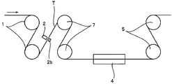
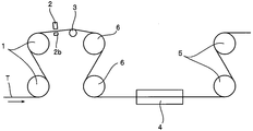
- FIG. 1 is an overall side view schematically showing a representative embodiment of a steam stretching apparatus applied to a method for producing a carbon fiber precursor acrylic fiber bundle according to the present invention. It is a top view which shows the relationship between the slit of the fluid ejection nozzle of the fiber-spreading apparatus in this invention, and the travel position of a carbon fiber precursor acrylic fiber bundle. It is the whole side view which shows other embodiment of the steam extending
- FIG. 1 schematically shows the overall configuration of a steam drawing apparatus applied to the method for producing a carbon fiber precursor acrylic fiber bundle of the present invention.
- the carbon fiber precursor acrylic fiber bundle steam drawing apparatus (hereinafter, simply referred to as drawing apparatus) in the present embodiment is a carbon fiber precursor carbon fiber T along the transfer direction.
- a publicly known method can be adopted about the process before and after steam extension.
- carbon fiber precursor acrylic fiber is subjected to solution spinning
- spinning is performed using a stock solution in which a homopolymer of acrylonitrile or an acrylonitrile copolymer containing a comonomer as a raw material polymer is dissolved in a known organic or inorganic solvent.
- the steam stretching of the present invention can be performed when stretching.
- the spinning method may be any of so-called wet, dry wet, and dry methods, and solvent removal, stretching in the bath, oil agent adhesion treatment, drying, and the like are performed in the subsequent steps.
- Steam drawing may be carried out at any stage in the process, but in the case of solution spinning, it is desirable to remove some of the solvent in the yarn, that is, after washing or drawing in a bath, or after drying. Further, any oil agent may be used, but the effect of the present invention becomes more remarkable when a silicone oil agent is used.
- the opening device 2 used in the present invention is preferably a method in which a fluid is blown to the carbon fiber precursor acrylic fiber bundle T and the fluid is passed through the carbon fiber precursor acrylic fiber bundle T to perform the opening.
- the flow rate of the gas ejected from the fluid ejection nozzle is 7 NL / min to 16 NL / min per 1000 dtex, and the flow rate is 130 m / sec to 350 m / sec. It is preferable to do.
- the flow rate is more preferably 10 NL / min to 14 NL / min, and the flow rate is more preferably 150 m / sec to 320 seconds and more preferably 230 seconds or less.
- the carbon fiber precursor acrylic fiber bundle T by opening the carbon fiber precursor acrylic fiber bundle T by spraying a fluid from a nozzle opening 2 a opened in a slit shape long in the width direction of the carbon fiber precursor acrylic fiber bundle T,
- the carbon fiber precursor acrylic fiber bundle T can be uniformly opened in the width direction, and can contribute to uniform stretching inside the steam box.
- a gas or a liquid can be used as the fluid sprayed from the nozzle opening 2a.
- the use of the gas is preferable because damage can be reduced and uniform opening can be performed.
- the type of gas is not particularly limited, but it is preferable to use air from the viewpoints of handleability and cost.
- the width of the carbon fiber precursor acrylic fiber bundle T is widened, but the nozzle opening width W1 of the fluid ejection nozzle and the just before the fiber opening device are expanded.
- the ratio (W1 / W2) to the width W2 of the carbon fiber precursor acrylic fiber bundle T on the roll 1 is preferably 1.2 or more and 2.0 or less.
- the holding angle of the carbon fiber precursor acrylic fiber bundle T to the roll is greater than 90 degrees and smaller than 210 degrees, and the carbon fiber precursor Due to the tension when the acrylic fiber bundle T is opened, there is no slip between the rolls 1 and 7 immediately before and after the opening device 2 and the carbon fiber precursor acrylic fiber bundle T, and the carbon fiber precursor acrylic fiber bundle fiber. Damage to the bundle T can be reduced.
- the diameter of the rolls 1 and 7 immediately before and after the fiber opening device is 300 mm or more and 600 mm or less, and immediately before and immediately before the fiber opening device 2 due to the tension when the carbon fiber precursor acrylic fiber bundle T is opened. No slip occurs between the rolls 1 and 7 and the carbon fiber precursor acrylic fiber bundle T, and damage to the carbon fiber precursor acrylic fiber bundle T can be reduced.
- the carbon fiber precursor acrylic fiber bundle T escapes to the opposite side of the ejection nozzle. Therefore, it is preferable to provide the fluid collision plate 2b in the direction in which the fluid is ejected from the ejection nozzle.
- the opening device 2 having the fluid collision plate 2b an air flow is generated between the ejection nozzle and the carbon fiber precursor acrylic fiber bundle T, and between the carbon fiber precursor acrylic fiber bundle T and the fluid collision plate 2b. And can be opened efficiently.
- the carbon fiber precursor acrylic fiber bundle T that has been subjected to the fiber opening treatment thus loses the converging property of the carbon fiber precursor acrylic fiber and easily spreads or divides, so when entering the transfer roll 7 or the steam box 4.
- the width of the carbon fiber precursor acrylic fiber bundle T varies or breaks and it is difficult to perform stable stretching.
- the width control device 3 after the fiber opening device 2 the width of the carbon fiber precursor acrylic fiber bundle T after the fiber opening treatment can be prevented from being increased, and the carbon fiber precursor after the fiber opening treatment.
- the width of the body acrylic fiber bundle T can be prevented from changing or cracking.
- uniform stretchability can be obtained inside the steam box 4 by controlling the opened carbon fiber precursor acrylic fiber bundle T so as to have a uniform thickness and a uniform width.
- a rotational drive roll, a free roll, a fixed roll, and a guide with a groove shape inscribed in a circumferentially parallel groove can be used.
- a free roll in which grooves parallel to the circumferential direction are engraved is preferable because it suppresses damage due to rubbing on the carbon fiber precursor acrylic fiber bundle T and obtains high-strength and high-quality carbon fibers.
- the groove shape of the width control device 3 in contact with the carbon fiber precursor acrylic fiber bundle T is a partial shape of an arc or an ellipse because the thickness can be made uniform. If the thickness of the carbon fiber precursor acrylic fiber bundle T can be made uniform and there is no problem of rubbing with the fibers, a part of the groove shape may be formed on a flat surface. It is preferable that the connecting portion between the flat surface and the curved surface is smoothly connected.
- the material of the width control device 3 is not particularly limited as long as it is a smooth material that does not damage the carbon fiber precursor acrylic fiber, but stainless steel, titanium, ceramic, etc. are preferable in terms of durability, and the surface is satin. Treatment or further plating treatment may be performed.
- the steam box 4 is supplied with saturated steam at an internal pressure of the steam box in order to plasticize the polymer constituting the carbon fiber precursor acrylic fiber and facilitate stretching, and the temperature is 120 to 167 ° C. If the saturated steam is 120 ° C. or higher, a plasticizing effect can be obtained, and it is practically difficult to use a saturated steam having a temperature of 167 ° C. or higher.
- the transfer roll 7 can be a heating roll 6 as shown in FIGS.
- the number and arrangement of the heating rolls 6 can be arbitrarily selected. It is preferable to dispose the heating roll 6 because the temperature of the carbon fiber precursor acrylic fiber is easily raised and the carbon fiber precursor acrylic fiber is easily stretched in the steam box 4.
- the stretching apparatus of the present invention can preheat the temperature of the carbon fiber precursor acrylic fiber bundle T to 80 to 160 ° C. by the heating roll 6. If the carbon fiber precursor acrylic fiber temperature is 80 ° C. or higher, it is preferable in terms of obtaining stretchability inside the steam box, and if it is 160 ° C. or lower, it is possible to suppress stretching before entering the steam box. Is preferable.
- the width of the carbon fiber precursor acrylic fiber bundle T after passing through the width control device 3 is 65 to 110% with respect to the width of the carbon fiber precursor acrylic fiber bundle T before being introduced into the supply roll 1. It is possible to control. In order to obtain the effect of plasticization by steam in the steam box 4 uniformly over the entire fiber bundle, the thickness of the carbon fiber precursor acrylic fiber bundle T is as uniform as possible, and the thickness of the fiber bundle is not increased. Better.
- the width of the carbon fiber precursor acrylic fiber bundle T after passing through the width control device 3 with respect to the width of the carbon fiber precursor acrylic fiber bundle T before introduction into the supply roll 1 is 65% or more, This is also preferable from the viewpoint of uniformly plasticizing the carbon fiber precursor acrylic fiber bundle T with steam.
- the width of the carbon fiber precursor acrylic fiber bundle T is widened by the fiber opening device 2, the carbon fiber precursor acrylic fiber bundle T is cracked, and it is necessary to prevent it.
- the fiber bundle width is 110% or less with respect to the carbon fiber precursor acrylic fiber bundle T before being introduced into the supply roll 1, it is easy to suppress cracking of the carbon fiber precursor acrylic fiber bundle T. More preferably, cracking of the fiber bundle is easily suppressed by narrowing the fiber bundle width to 100% or less.
- a known method can be used for the steam property inside the steam box and the shape of the sealing device (not shown).
- ⁇ Running stability> The fiber bundle width measured by measuring the carbon fiber precursor acrylic fiber bundle width at a position 100 mm upstream from the steam box entrance using a straight scale conforming to JIS B7516 150 mm grade 1, and obtaining a yarn length of 5000 m. Fluctuation was calculated from [maximum width-minimum width] from the maximum width and the minimum width of and the fluctuation rate was calculated by [variation] / [maximum width] ⁇ 100 (%). When this variation rate was 20% or more and when the fiber bundle was cracked, it was evaluated as x, and when the variation rate was less than 20% and there was no problem in running stability, it was evaluated as ⁇ .
- ⁇ Measurement of fiber bundle temperature The temperature of the carbon fiber precursor acrylic fiber bundle at the time of exiting the heating roll was measured by a radiation thermometer at the carbon fiber precursor acrylic fiber bundle temperature at a position 100 mm downstream from the roll. Moreover, the temperature of the carbon fiber precursor acrylic fiber bundle when entering the steam box was measured with a radiation thermometer at the carbon fiber precursor acrylic fiber bundle temperature at a position 100 mm upstream from the steam box inlet.
- ⁇ Thickness unevenness of carbon fiber precursor acrylic fiber bundle The thickness of the carbon fiber precursor acrylic fiber bundle on the roll surface immediately before entering the steam box is measured for 100 m in the running direction of the carbon fiber precursor acrylic fiber bundle with a two-dimensional laser displacement meter (LJ-G200, manufactured by Keyence Corporation).
- the thickness of the carbon fiber precursor acrylic fiber bundle in the width direction is ⁇ 0.05 mm or less, ⁇ is ⁇ 0.05 mm to 0.08 mm, ⁇ is more than ⁇ 0.08 mm, and ⁇ did.
- ⁇ Quality> The case where the number of fluffs was 1 or less in 5 minutes was evaluated as ⁇ , and the range of 2 or more and 4 or less was ⁇ , and the case where the number was 5 or more was evaluated as ⁇ .
- Example 1 A polymer having an intrinsic viscosity [ ⁇ ] of 1.8 consisting of 98% by mass of acrylonitrile and 2% by mass of methacrylic acid was dissolved in dimethylformamide to prepare a spinning dope having a polymer concentration of 23% by mass. This spinning dope was filtered through 20 ⁇ m and 5 ⁇ m filters, held at 65 ° C., and spun coagulated yarn was obtained by dry and wet spinning using a die having a diameter of 0.15 mm and a hole number of 2000.
- a fluid ejection nozzle having a fluid ejection nozzle having a 1 mm slit shown in FIG. Compressed air was supplied at 400 NL / minute to open the carbon fiber precursor acrylic fiber bundle, and the carbon fiber precursor acrylic fiber bundle was introduced into the steam box while being transferred by the transfer roll 7.
- the distance between the supply roll 1 and the opening device 2 was 350 mm, and the distance between the opening device 2 and the transfer roll was 900 mm.
- the total fineness of the yarn on the supply roll at this time was 35040 dtex, the flow rate of the gas ejected from the fluid ejection nozzle was 11.5 NL / min per 1000 dtex, and the flow rate was 159 m / sec.
- the diameters of the supply roll 1 and the transfer roll 7 were 352 mm, and the thread holding angle to the supply roll 1 and the transfer roll 7 was 122 degrees.
- the carbon fiber precursor acrylic fiber bundle temperature when introduced into the steam box was 55 ° C.
- the take-up roll was rotated at a rotation speed four times that of the transfer roll, and the carbon fiber precursor acrylic fiber bundle was taken up to obtain a carbon fiber precursor acrylic fiber bundle having a fineness of 0.73 dtex.
- Example 2 A carbon fiber precursor acrylic fiber bundle was obtained in the same procedure as in Example 1 except that the slit length of the fluid ejection nozzle and the flow rate of the compressed air were changed as shown in Table 1. The results are shown in Tables 1 and 2 and FIG.
- Example 5 A carbon fiber precursor acrylic fiber bundle was obtained in the same procedure as in Example 1 except that the diameters of the supply roll 1 and the transfer roll 7 were changed to 500 mm. The results are shown in Tables 1 and 2.
- Example 6 As illustrated in FIG. 3, a carbon fiber precursor acrylic fiber bundle was obtained in the same procedure as in Example 1 except that the holding angle of the supply roll 1, the transfer roll 7, and the yarn was changed to 193 degrees. The results are shown in Tables 1 and 2.
- Example 7 As illustrated in FIG. 4, after opening the carbon fiber precursor acrylic fiber bundle using the opening device 2, the arc shape of R36 in the circumferential direction is located 700 mm from the opening device 2 in the fiber bundle transfer direction.
- the carbon fiber precursor acrylic fiber bundle is passed through the groove of a free roll (hereinafter referred to as width control device 3) having a groove cross section, and the width of the fiber bundle is controlled and transferred by the heating roll 6 to the steam box.
- a carbon fiber precursor acrylic fiber bundle was obtained in the same procedure as in Example 1 except that it was introduced. The results are shown in Tables 1 and 2.
- Example 7 the temperature of the heating roll 6 was changed to change the temperature of the carbon fiber precursor acrylic fiber bundle when the steam box was introduced.
- the results at this time are shown in Tables 1 and 2.
- the take-up roll speed / heated roll speed when the take-up roll speed was broken while gradually increasing the take-up roll speed was obtained. This is shown in FIG. If the value of the take-up roll speed / heating roll speed at break is large, it indicates that the film is easily stretched in the steam box.
- Example 8 A carbon fiber precursor acrylic fiber bundle was obtained in the same procedure as in Example 7 except that the final fineness was changed. The results are shown in Tables 1 and 2.
- Example 9 A carbon fiber precursor acrylic fiber bundle was obtained in the same procedure as in Example 8 except that the take-up roll speed / supply roll speed was set to 3. The results are shown in Tables 1 and 2.
- Example 10 A carbon fiber precursor acrylic fiber bundle was obtained in the same procedure as in Example 7 using a fixed guide in which a groove having an arc-shaped cross section was formed as the width control device 3. The results are shown in Tables 1 and 2.
- Example 11 A carbon fiber precursor acrylic fiber bundle was obtained in the same procedure as in Example 7 except that the groove shape of the width control device 3 was changed. The results are shown in Tables 1 and 2.
- Example 12 A carbon fiber precursor acrylic fiber bundle was obtained in the same procedure as in Example 7 except that the final spinning speed was changed to 300 mm / min. The results are shown in Tables 1 and 2.
- Example 13 A carbon fiber precursor acrylic fiber bundle was obtained in the same procedure as in Example 12 except that the take-up roll speed / supply roll speed was 3.5. The results are shown in Tables 1 and 2.
- Example 14 Three coagulated yarns obtained in the same manner as in Example 1 were combined to obtain a coagulated yarn of a carbon fiber precursor acrylic fiber bundle of 6000 filaments. Thereafter, stretching was carried out in the same manner as in Example 7 using a fiber jet nozzle having a 1 mm slit opened in the fiber bundle width direction by 23 mm and a fluid impingement plate to obtain a carbon fiber precursor acrylic fiber bundle. The results are shown in Tables 1 and 2.
- Example 15 A carbon fiber precursor acrylic fiber bundle was obtained in the same procedure as in Example 7 except that the roll shape of the width control device 3 was a small one with a small curvature. The results are shown in Tables 1 and 2.
- Examples 16 to 18 A carbon fiber precursor acrylic fiber bundle was obtained in the same procedure as in Example 7 except that the distance between the opening device 2 and the width control device 3 was changed as shown in Tables 1 and 2. The results are shown in Tables 1 and 2.
- Example 19 As shown in FIG. 10, the distance between the opening device 2 and the width control device 3 is 400 mm, the fiber bundle width C after opening is 24 mm, and the fiber bundle width D after width control is 21 mm. A carbon fiber precursor acrylic fiber bundle was obtained in the same procedure as in FIG. The results are shown in Tables 1 and 2.
- a carbon fiber precursor acrylic fiber bundle was obtained in the same procedure as in Example 7 except that the roll shape of the width control device 3 was a small curvature. The results are shown in Tables 1 and 2.
- Example 1 A carbon fiber precursor acrylic fiber bundle was obtained in the same procedure as in Example 1 except that the flow rate of the compressed air ejected from the fluid ejection nozzle was changed to 275 NL / min. The results are shown in Tables 1 and 2.
- Example 2 The carbon fiber precursor acrylic fiber bundle was obtained in the same procedure as in Example 1 except that the slit length of the fluid ejection nozzle was changed to 0.5 mm and the flow rate of the compressed air was changed to 138 NL / min. Thread breakage occurred before the desired roll speed was reached, and no carbon fiber precursor acrylic fiber bundle was obtained.
Landscapes
- Engineering & Computer Science (AREA)
- Textile Engineering (AREA)
- Mechanical Engineering (AREA)
- Inorganic Fibers (AREA)
- Yarns And Mechanical Finishing Of Yarns Or Ropes (AREA)
- Artificial Filaments (AREA)
Abstract
Priority Applications (3)
| Application Number | Priority Date | Filing Date | Title |
|---|---|---|---|
| CN201280026936.0A CN103562452B (zh) | 2011-06-03 | 2012-05-31 | 碳纤维前体丙烯腈纤维束的制造方法 |
| EP12793024.6A EP2716802B1 (fr) | 2011-06-03 | 2012-05-31 | Procédé de fabrication d'un faisceau de fibres acryliques précurseurs de fibres de carbone |
| US14/123,361 US9388516B2 (en) | 2011-06-03 | 2012-05-31 | Method for producing carbon-fiber-precursor acrylic fiber bundle |
Applications Claiming Priority (2)
| Application Number | Priority Date | Filing Date | Title |
|---|---|---|---|
| JP2011-125253 | 2011-06-03 | ||
| JP2011125253 | 2011-06-03 |
Publications (1)
| Publication Number | Publication Date |
|---|---|
| WO2012165574A1 true WO2012165574A1 (fr) | 2012-12-06 |
Family
ID=47259426
Family Applications (1)
| Application Number | Title | Priority Date | Filing Date |
|---|---|---|---|
| PCT/JP2012/064146 Ceased WO2012165574A1 (fr) | 2011-06-03 | 2012-05-31 | Procédé de fabrication d'un faisceau de fibres acryliques précurseurs de fibres de carbone |
Country Status (5)
| Country | Link |
|---|---|
| US (1) | US9388516B2 (fr) |
| EP (1) | EP2716802B1 (fr) |
| JP (1) | JP5621848B2 (fr) |
| CN (1) | CN103562452B (fr) |
| WO (1) | WO2012165574A1 (fr) |
Cited By (2)
| Publication number | Priority date | Publication date | Assignee | Title |
|---|---|---|---|---|
| JP2014129630A (ja) * | 2012-12-29 | 2014-07-10 | Uni Charm Corp | 開繊された繊維束の製造方法、清掃部材の製造方法、繊維束の開繊装置、及び清掃部材の製造システム |
| WO2014203880A1 (fr) * | 2013-06-21 | 2014-12-24 | 三菱レイヨン株式会社 | Processus de fabrication d'un faisceau de fibres acryliques précurseur de fibres de carbone et appareil d'étirage à la vapeur |
Families Citing this family (6)
| Publication number | Priority date | Publication date | Assignee | Title |
|---|---|---|---|---|
| IT201700035017A1 (it) | 2017-03-30 | 2018-09-30 | M A E S P A | Metodo per l'apertura di un fascio di fibre tessili, preferibilmente fibre chimiche o inorganiche |
| KR102555678B1 (ko) * | 2018-03-27 | 2023-07-17 | 도레이 카부시키가이샤 | 아크릴로니트릴계 섬유 다발의 제조 방법 및 탄소 섬유 다발의 제조 방법 |
| CN118065028A (zh) * | 2022-11-24 | 2024-05-24 | 远景能源有限公司 | 一种提高腈纶力学性能的牵伸设备系统与牵伸方法 |
| CN117166070A (zh) * | 2023-08-25 | 2023-12-05 | 山西钢科碳材料有限公司 | 一种聚丙烯腈纤维及其制备方法 |
| CN118932508A (zh) * | 2024-07-30 | 2024-11-12 | 山西钢科碳材料有限公司 | 一种聚丙烯腈纤维及其制备方法 |
| US20260049419A1 (en) * | 2024-08-13 | 2026-02-19 | North Carolina State University | Apparatus and method for improving yarn strength and hairiness in singles ring yarns |
Citations (5)
| Publication number | Priority date | Publication date | Assignee | Title |
|---|---|---|---|---|
| JPS61231213A (ja) * | 1985-03-30 | 1986-10-15 | Asahi Chem Ind Co Ltd | 炭素繊維用前駆体の製造方法 |
| JPH0770862A (ja) | 1993-08-30 | 1995-03-14 | Toray Ind Inc | 糸条のスチーム延伸装置および延伸方法 |
| JPH1112874A (ja) * | 1997-06-19 | 1999-01-19 | Toray Ind Inc | アクリル系糸条およびアクリル系糸条のスチーム延伸方法および装置および炭素繊維 |
| JPH11286845A (ja) | 1998-03-31 | 1999-10-19 | Toray Ind Inc | アクリル系延伸フィラメント糸条の製造方法 |
| JP2002309438A (ja) * | 2001-04-17 | 2002-10-23 | Toho Tenax Co Ltd | アクリル系繊維の製造方法 |
Family Cites Families (18)
| Publication number | Priority date | Publication date | Assignee | Title |
|---|---|---|---|---|
| US3120027A (en) * | 1962-05-23 | 1964-02-04 | Monsanto Chemicals | Method and apparatus for treating yarn |
| BE634439A (fr) * | 1962-07-03 | |||
| US3255506A (en) * | 1963-02-20 | 1966-06-14 | Eastman Kodak Co | Tow treatment |
| US3380131A (en) * | 1964-07-13 | 1968-04-30 | Fiber Industries Inc | Method and apparatus deflecting and drawing tow |
| US3546722A (en) * | 1964-12-30 | 1970-12-15 | Celanese Corp | Cushioning material |
| US3535745A (en) * | 1967-09-18 | 1970-10-27 | Eastman Kodak Co | Method and apparatus for opening multifilament tows |
| US4571793A (en) * | 1983-03-02 | 1986-02-25 | Enterprise Machine And Development Corp. | Air jet texturing system for the production of uniform textured yarn |
| US5082611A (en) * | 1988-07-15 | 1992-01-21 | E. I. Du Pont De Nemours And Company | Process for spinning and drawing monofilaments with high tenacity and high tensile uniformity |
| CA2080621A1 (fr) * | 1992-03-30 | 1993-10-01 | George M. Kent | Procede de filature et d'etirage en continu de polyamide et installation utilisee a ces fins |
| JP2692513B2 (ja) * | 1992-11-10 | 1997-12-17 | 東レ株式会社 | ポリエステル繊維の製造方法および装置 |
| JP2001020140A (ja) * | 1999-07-06 | 2001-01-23 | Mitsubishi Rayon Co Ltd | 炭素繊維前駆体の駆動装置 |
| US6543106B1 (en) * | 1999-10-25 | 2003-04-08 | Celanese Acetate, Llc | Apparatus, method and system for air opening of textile tow and opened textile tow web produced thereby |
| EP1719829B1 (fr) * | 2004-02-13 | 2010-07-14 | Mitsubishi Rayon Co., Ltd. | Faisceau de fibres precurseur des fibres de carbone, leurs methode et dispositif de production, et fibres de carbone et leur methode de production |
| DE102005052660B3 (de) * | 2005-11-04 | 2007-04-26 | Karl Mayer Malimo Textilmaschinenfabrik Gmbh | Vorrichtung und Verfahren zum Ausbreiten eines Karbonfaserstrangs |
| US20080113574A1 (en) * | 2006-11-14 | 2008-05-15 | Neron Rene B | Wound care product made from bulked filament tow |
| JP5457736B2 (ja) * | 2009-06-24 | 2014-04-02 | 三菱レイヨン株式会社 | 炭素繊維束の製造方法、および炭素繊維束の製造装置 |
| MX2013009249A (es) * | 2011-02-10 | 2013-11-04 | Mitsubishi Rayon Co | Un aparato de tratamiento por vapor a presion de un haz de fibras acrilicas precursoras de fibras de carbono y un metodo para producir un haz de fibras acrilicas. |
| CN103764891B (zh) * | 2011-08-22 | 2015-05-13 | 三菱丽阳株式会社 | 蒸汽拉伸装置 |
-
2012
- 2012-05-31 WO PCT/JP2012/064146 patent/WO2012165574A1/fr not_active Ceased
- 2012-05-31 CN CN201280026936.0A patent/CN103562452B/zh active Active
- 2012-05-31 US US14/123,361 patent/US9388516B2/en active Active
- 2012-05-31 JP JP2012526206A patent/JP5621848B2/ja active Active
- 2012-05-31 EP EP12793024.6A patent/EP2716802B1/fr active Active
Patent Citations (5)
| Publication number | Priority date | Publication date | Assignee | Title |
|---|---|---|---|---|
| JPS61231213A (ja) * | 1985-03-30 | 1986-10-15 | Asahi Chem Ind Co Ltd | 炭素繊維用前駆体の製造方法 |
| JPH0770862A (ja) | 1993-08-30 | 1995-03-14 | Toray Ind Inc | 糸条のスチーム延伸装置および延伸方法 |
| JPH1112874A (ja) * | 1997-06-19 | 1999-01-19 | Toray Ind Inc | アクリル系糸条およびアクリル系糸条のスチーム延伸方法および装置および炭素繊維 |
| JPH11286845A (ja) | 1998-03-31 | 1999-10-19 | Toray Ind Inc | アクリル系延伸フィラメント糸条の製造方法 |
| JP2002309438A (ja) * | 2001-04-17 | 2002-10-23 | Toho Tenax Co Ltd | アクリル系繊維の製造方法 |
Non-Patent Citations (1)
| Title |
|---|
| See also references of EP2716802A4 |
Cited By (8)
| Publication number | Priority date | Publication date | Assignee | Title |
|---|---|---|---|---|
| JP2014129630A (ja) * | 2012-12-29 | 2014-07-10 | Uni Charm Corp | 開繊された繊維束の製造方法、清掃部材の製造方法、繊維束の開繊装置、及び清掃部材の製造システム |
| WO2014203880A1 (fr) * | 2013-06-21 | 2014-12-24 | 三菱レイヨン株式会社 | Processus de fabrication d'un faisceau de fibres acryliques précurseur de fibres de carbone et appareil d'étirage à la vapeur |
| JP5831638B2 (ja) * | 2013-06-21 | 2015-12-09 | 三菱レイヨン株式会社 | 炭素繊維前駆体アクリル繊維束の製造方法及びスチーム延伸装置 |
| CN105358746A (zh) * | 2013-06-21 | 2016-02-24 | 三菱丽阳株式会社 | 碳纤维前体丙烯腈纤维束的制造方法及蒸汽拉伸装置 |
| EP3012360A4 (fr) * | 2013-06-21 | 2016-06-29 | Mitsubishi Rayon Co | Processus de fabrication d'un faisceau de fibres acryliques précurseur de fibres de carbone et appareil d'étirage à la vapeur |
| KR101744490B1 (ko) * | 2013-06-21 | 2017-06-08 | 미쯔비시 케미컬 주식회사 | 탄소섬유 전구체 아크릴 섬유속의 제조 방법 및 스팀 연신 장치 |
| CN105358746B (zh) * | 2013-06-21 | 2018-02-23 | 三菱化学株式会社 | 碳纤维前体丙烯腈纤维束的制造方法及蒸汽拉伸装置 |
| US10604871B2 (en) | 2013-06-21 | 2020-03-31 | Mitsubishi Chemical Corporation | Process for steam drawing carbon-fiber precursor acrylic fiber bundle |
Also Published As
| Publication number | Publication date |
|---|---|
| JP5621848B2 (ja) | 2014-11-12 |
| CN103562452A (zh) | 2014-02-05 |
| US9388516B2 (en) | 2016-07-12 |
| EP2716802A1 (fr) | 2014-04-09 |
| EP2716802A4 (fr) | 2014-11-26 |
| US20140115848A1 (en) | 2014-05-01 |
| JPWO2012165574A1 (ja) | 2015-02-23 |
| EP2716802B1 (fr) | 2020-02-26 |
| CN103562452B (zh) | 2016-04-20 |
Similar Documents
| Publication | Publication Date | Title |
|---|---|---|
| JP5621848B2 (ja) | 炭素繊維前駆体アクリル繊維束の製造方法 | |
| JP4968378B2 (ja) | 乾湿式紡糸用スピニングパック、および繊維束の製造装置 | |
| JP5831638B2 (ja) | 炭素繊維前駆体アクリル繊維束の製造方法及びスチーム延伸装置 | |
| CN111868315A (zh) | 丙烯腈系纤维束的制造方法及碳纤维束的制造方法 | |
| JP5430774B2 (ja) | スチーム延伸装置 | |
| JP6098033B2 (ja) | アクリル繊維束の製造方法と同繊維束のスチーム延伸装置 | |
| JP6149583B2 (ja) | 炭素繊維前駆体アクリル繊維束の延伸方法 | |
| CN110402307B (zh) | 丙烯腈系纤维束的制造方法和碳纤维束的制造方法 | |
| JP4801621B2 (ja) | 炭素繊維前駆体トウの製造方法 | |
| JP4673095B2 (ja) | 加圧スチーム延伸装置およびアクリル系繊維の製造方法 | |
| JP2008240203A (ja) | スチーム延伸装置および炭素繊維用前駆体糸条の製造方法 | |
| JP4745932B2 (ja) | 加圧スチームによる繊維の延伸装置および炭素繊維用アクリル系前駆体繊維束の製造方法 | |
| JP4500088B2 (ja) | 熱可塑性糸条に付着した微粉末の除去方法及びその装置 | |
| JP4332401B2 (ja) | 加圧スチーム延伸装置およびアクリル系繊維の製造方法 | |
| JP4446817B2 (ja) | アクリル系炭素繊維前駆体繊維束の製造方法 | |
| JP6265068B2 (ja) | 炭素繊維前駆体アクリル繊維束の製造方法 |
Legal Events
| Date | Code | Title | Description |
|---|---|---|---|
| WWE | Wipo information: entry into national phase |
Ref document number: 201280026936.0 Country of ref document: CN |
|
| ENP | Entry into the national phase |
Ref document number: 2012526206 Country of ref document: JP Kind code of ref document: A |
|
| 121 | Ep: the epo has been informed by wipo that ep was designated in this application |
Ref document number: 12793024 Country of ref document: EP Kind code of ref document: A1 |
|
| WWE | Wipo information: entry into national phase |
Ref document number: 14123361 Country of ref document: US |
|
| NENP | Non-entry into the national phase |
Ref country code: DE |