WO2012169059A1 - Stator de machine électrique tournante, procédé de fabrication d'un stator de machine électrique tournante, et machine électrique tournante - Google Patents
Stator de machine électrique tournante, procédé de fabrication d'un stator de machine électrique tournante, et machine électrique tournante Download PDFInfo
- Publication number
- WO2012169059A1 WO2012169059A1 PCT/JP2011/063354 JP2011063354W WO2012169059A1 WO 2012169059 A1 WO2012169059 A1 WO 2012169059A1 JP 2011063354 W JP2011063354 W JP 2011063354W WO 2012169059 A1 WO2012169059 A1 WO 2012169059A1
- Authority
- WO
- WIPO (PCT)
- Prior art keywords
- stator
- coil
- core
- insulator
- inter
- Prior art date
- Legal status (The legal status is an assumption and is not a legal conclusion. Google has not performed a legal analysis and makes no representation as to the accuracy of the status listed.)
- Ceased
Links
Images


Classifications
-
- H—ELECTRICITY
- H02—GENERATION; CONVERSION OR DISTRIBUTION OF ELECTRIC POWER
- H02K—DYNAMO-ELECTRIC MACHINES
- H02K3/00—Details of windings
- H02K3/32—Windings characterised by the shape, form or construction of the insulation
- H02K3/325—Windings characterised by the shape, form or construction of the insulation for windings on salient poles, such as claw-shaped poles
-
- H—ELECTRICITY
- H02—GENERATION; CONVERSION OR DISTRIBUTION OF ELECTRIC POWER
- H02K—DYNAMO-ELECTRIC MACHINES
- H02K15/00—Processes or apparatus specially adapted for manufacturing, assembling, maintaining or repairing of dynamo-electric machines
- H02K15/08—Forming windings by laying conductors into or around core parts
- H02K15/095—Forming windings by laying conductors into or around core parts by laying conductors around salient poles
-
- H—ELECTRICITY
- H02—GENERATION; CONVERSION OR DISTRIBUTION OF ELECTRIC POWER
- H02K—DYNAMO-ELECTRIC MACHINES
- H02K15/00—Processes or apparatus specially adapted for manufacturing, assembling, maintaining or repairing of dynamo-electric machines
- H02K15/10—Applying solid insulation to windings, stators or rotors, e.g. applying insulating tapes
Definitions
- the conventional rotating electric machine stator as described above is manufactured as follows. That is, after producing a band-shaped core unit in which a plurality of stator pieces each including magnetic teeth are connected so as to be bendable, the stator pieces exposed in the space between the magnetic teeth with the space between the magnetic teeth expanded. Is covered with a film-like insulating material, and a part of the film-like insulating material is projected from each stator piece as a bent portion. Thereafter, a coil is provided on each magnetic teeth by winding a conductive wire around each magnetic teeth using a winding machine, and then the core unit is bent in a direction in which the magnetic teeth approach each other.
- a method of manufacturing a stator of a rotating electrical machine includes a core back piece assembly including a plurality of core back pieces connected to each other so as to be bendable, and a plurality of magnetic teeth portions projecting from each core back piece.
- An insulating layer is provided as an insulator between coil cores on the surface surrounding the space between each magnetic tooth portion of the surface of the core-unformed unit, and the portions overlapping the core back pieces of the coil core insulator are overlapped with the core back pieces.
- Stator coil mounting process, stator coil mounting process for providing a stator coil to each of the magnetic tooth portions via the coil core insulator after the coil iron core insulator mounting process and the coil core insulator mounting process.
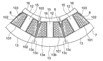
- the rotor 2 is rotatable with respect to the stator 3 about the axis of the rotating electrical machine 1.
- the rotor 2 is fixed to a cylindrical rotor core 4 formed by laminating a plurality of steel plates in the axial direction, and the outer peripheral surface of the rotor core 4, and is arranged in the circumferential direction of the rotor core 4.
- the plurality of permanent magnets 5 are disposed on the axis of the rotating electrical machine 1, and the rotor shaft 6 is fixed to the rotor core 4 while passing through the center of the rotor core 4.
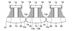
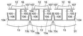
- the distance between the magnetic tooth portions 12 is wider than the completed stator iron core 7.
- the core back piece coupling body 32 the core back piece end faces 13c of the core back pieces 13 are separated from each other.
- the iron core-unformed unit 31 has a shape in which the stator iron core 7 is developed in a strip shape in a direction in which the distance between the magnetic pole tooth portions 12 increases.
- an insulating layer is provided as an insulator 9 between the coil cores on the surface surrounding the space between the magnetic pole teeth 12 on the surface of the core unformed unit 31. . That is, an insulating layer is provided on each side surface of each magnetic pole tooth portion 12 and each inner surface 13a of the core back piece, and an insulating layer overlapping the side surface of each magnetic pole tooth portion 12 is used as the tooth overlap portion 19 and overlaps each inner surface 13a of the core back piece.
- the insulating layer is a core back piece overlapped portion 20.
- the insulator between coil iron cores 9 is provided on the iron core-unformed unit 31 by resin molding (coil iron core insulator mounting step).
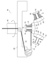
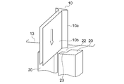
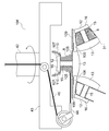
- the insertion portion 10a of the inter-coil insulator 10 is inserted into the insertion groove 22 and is elastically deformed by being pushed by the inner surface of the insertion groove 22, the insertion portion 10a is inserted by the elastic restoring force of the insertion portion 10a.
- the insertion portion 10a can be stretched within the groove 22, and the inter-coil insulator 10 can be more reliably held on the stator core 7.
Landscapes
- Engineering & Computer Science (AREA)
- Power Engineering (AREA)
- Manufacture Of Motors, Generators (AREA)
- Insulation, Fastening Of Motor, Generator Windings (AREA)
Abstract
Selon la présente invention, un noyau de stator entourant la périphérie d'un rotor comprend : une section tubulaire ; et plusieurs sections dents de pôle magnétique disposées à intervalles dans la direction circonférentielle de la section tubulaire, chacune d'entre elles dépassant de la section tubulaire vers l'intérieur dans la direction du diamètre. Chaque section dent de pôle magnétique comporte une bobine de stator. Un isolateur bobine-noyau se trouve entre la bobine de stator et le noyau de stator afin d'assurer l'isolation entre la bobine de stator et le noyau de stator. Cet isolateur bobine-noyau présente une section de chevauchement de section tubulaire destinée à être chevauchée par la surface circonférentielle intérieure de la section tubulaire. Un isolateur inter-bobines se situe entre les bobines de stator afin d'assurer l'isolation entre ces bobines de stator. Une rainure d'insertion, qui s'ouvre vers l'intérieur dans la direction du diamètre du noyau de stator, est présente à l'emplacement de la section de chevauchement de section tubulaire dans la direction axiale du noyau de stator. Ledit isolateur inter-bobines est fixé sur le noyau de stator grâce à l'insertion de l'isolateur inter-bobines dans la rainure d'insertion par glissement d'une section d'insertion, qui constitue une partie de l'isolateur inter-bobines, dans le sens de la longueur de la rainure d'insertion.
Priority Applications (1)
| Application Number | Priority Date | Filing Date | Title |
|---|---|---|---|
| PCT/JP2011/063354 WO2012169059A1 (fr) | 2011-06-10 | 2011-06-10 | Stator de machine électrique tournante, procédé de fabrication d'un stator de machine électrique tournante, et machine électrique tournante |
Applications Claiming Priority (1)
| Application Number | Priority Date | Filing Date | Title |
|---|---|---|---|
| PCT/JP2011/063354 WO2012169059A1 (fr) | 2011-06-10 | 2011-06-10 | Stator de machine électrique tournante, procédé de fabrication d'un stator de machine électrique tournante, et machine électrique tournante |
Publications (1)
| Publication Number | Publication Date |
|---|---|
| WO2012169059A1 true WO2012169059A1 (fr) | 2012-12-13 |
Family
ID=47295661
Family Applications (1)
| Application Number | Title | Priority Date | Filing Date |
|---|---|---|---|
| PCT/JP2011/063354 Ceased WO2012169059A1 (fr) | 2011-06-10 | 2011-06-10 | Stator de machine électrique tournante, procédé de fabrication d'un stator de machine électrique tournante, et machine électrique tournante |
Country Status (1)
| Country | Link |
|---|---|
| WO (1) | WO2012169059A1 (fr) |
Cited By (8)
| Publication number | Priority date | Publication date | Assignee | Title |
|---|---|---|---|---|
| US20150280508A1 (en) * | 2012-11-14 | 2015-10-01 | Mitsubishi Electric Corporation | Rotary electric machine stator and rotary electric machine |
| CN106849445A (zh) * | 2017-03-28 | 2017-06-13 | 天津市永亮水电设备制造有限公司 | 一种发电机定子端部绝缘支架 |
| CN107528400A (zh) * | 2017-09-30 | 2017-12-29 | 广东美芝制冷设备有限公司 | 电机转子、永磁电机和压缩机 |
| JP2018074693A (ja) * | 2016-10-27 | 2018-05-10 | トヨタ自動車株式会社 | 回転電機のステータ |
| WO2019062130A1 (fr) * | 2017-09-30 | 2019-04-04 | 广东美芝制冷设备有限公司 | Rotor de moteur, moteur à aimants permanents et compresseur |
| WO2019132338A1 (fr) * | 2017-12-26 | 2019-07-04 | 엘지이노텍 주식회사 | Stator et moteur le comprenant |
| JP7394501B1 (ja) | 2023-06-26 | 2023-12-08 | E-Tec株式会社 | 固定子、固定子製造方法および固定子製造装置 |
| US11962207B2 (en) * | 2022-08-22 | 2024-04-16 | Beta Air, Llc | Methods and apparatus for manufacturing a stator for an electric aircraft motor |
Citations (4)
| Publication number | Priority date | Publication date | Assignee | Title |
|---|---|---|---|---|
| JPH09191588A (ja) * | 1995-11-02 | 1997-07-22 | Mitsubishi Electric Corp | 回転電機及びその製造方法 |
| JP2002171704A (ja) * | 2000-12-05 | 2002-06-14 | Ebara Corp | 突極集中巻線電動機 |
| JP2006320136A (ja) * | 2005-05-13 | 2006-11-24 | Mitsubishi Electric Corp | 回転電機の固定子 |
| JP2010246325A (ja) * | 2009-04-09 | 2010-10-28 | Daikin Ind Ltd | 固定子、モータ及び圧縮機 |
-
2011
- 2011-06-10 WO PCT/JP2011/063354 patent/WO2012169059A1/fr not_active Ceased
Patent Citations (4)
| Publication number | Priority date | Publication date | Assignee | Title |
|---|---|---|---|---|
| JPH09191588A (ja) * | 1995-11-02 | 1997-07-22 | Mitsubishi Electric Corp | 回転電機及びその製造方法 |
| JP2002171704A (ja) * | 2000-12-05 | 2002-06-14 | Ebara Corp | 突極集中巻線電動機 |
| JP2006320136A (ja) * | 2005-05-13 | 2006-11-24 | Mitsubishi Electric Corp | 回転電機の固定子 |
| JP2010246325A (ja) * | 2009-04-09 | 2010-10-28 | Daikin Ind Ltd | 固定子、モータ及び圧縮機 |
Cited By (12)
| Publication number | Priority date | Publication date | Assignee | Title |
|---|---|---|---|---|
| US20150280508A1 (en) * | 2012-11-14 | 2015-10-01 | Mitsubishi Electric Corporation | Rotary electric machine stator and rotary electric machine |
| US9847688B2 (en) | 2012-11-14 | 2017-12-19 | Mitsubishi Electric Corporation | Rotary electric machine stator and rotary electric machine |
| JP2018074693A (ja) * | 2016-10-27 | 2018-05-10 | トヨタ自動車株式会社 | 回転電機のステータ |
| CN106849445A (zh) * | 2017-03-28 | 2017-06-13 | 天津市永亮水电设备制造有限公司 | 一种发电机定子端部绝缘支架 |
| CN106849445B (zh) * | 2017-03-28 | 2023-03-21 | 天津市永亮水电设备制造有限公司 | 一种发电机定子端部绝缘支架 |
| CN107528400A (zh) * | 2017-09-30 | 2017-12-29 | 广东美芝制冷设备有限公司 | 电机转子、永磁电机和压缩机 |
| WO2019062130A1 (fr) * | 2017-09-30 | 2019-04-04 | 广东美芝制冷设备有限公司 | Rotor de moteur, moteur à aimants permanents et compresseur |
| WO2019132338A1 (fr) * | 2017-12-26 | 2019-07-04 | 엘지이노텍 주식회사 | Stator et moteur le comprenant |
| US11496012B2 (en) | 2017-12-26 | 2022-11-08 | Lg Innotek Co., Ltd. | Stator and motor including same |
| US11962207B2 (en) * | 2022-08-22 | 2024-04-16 | Beta Air, Llc | Methods and apparatus for manufacturing a stator for an electric aircraft motor |
| JP7394501B1 (ja) | 2023-06-26 | 2023-12-08 | E-Tec株式会社 | 固定子、固定子製造方法および固定子製造装置 |
| JP2025004386A (ja) * | 2023-06-26 | 2025-01-15 | E-Tec株式会社 | 固定子、固定子製造方法および固定子製造装置 |
Similar Documents
| Publication | Publication Date | Title |
|---|---|---|
| JP5938903B2 (ja) | 電動機 | |
| US9172280B2 (en) | Conductor and rotating electrical machine with a covering material | |
| CN102801242B (zh) | 旋转电机 | |
| WO2012169059A1 (fr) | Stator de machine électrique tournante, procédé de fabrication d'un stator de machine électrique tournante, et machine électrique tournante | |
| JP5953672B2 (ja) | モータ | |
| CN109075668B (zh) | 电枢的制造方法、旋转电机的制造方法、电枢、旋转电机及电枢的制造装置 | |
| JP5028234B2 (ja) | 回転電機、及び固定子の製造方法 | |
| JP2012139075A (ja) | 回転電機 | |
| US20130192057A1 (en) | Manufacturing method for coil unit | |
| US11018543B2 (en) | Method for manufacturing stator of rotary electric machine including a cassette coil | |
| US20130193798A1 (en) | Rotary electric machine | |
| CN103733482A (zh) | 旋转电机的定子和旋转电机 | |
| JP2009261189A (ja) | 回転電機のコイル組立体製造方法 | |
| CN111245164A (zh) | 旋转电机及其制造方法 | |
| TW201742356A (zh) | 軸向間隙型旋轉電機 | |
| JP2019088139A (ja) | ステータおよび回転電機 | |
| JP6062134B1 (ja) | 固定子および電動機 | |
| WO2015174277A1 (fr) | Machine électrique tournante et son procédé de fabrication | |
| JP2017028831A (ja) | 回転電機ステータ | |
| JP5309674B2 (ja) | 固定子コイルの製造方法 | |
| JP5152578B2 (ja) | 回転電機のコイル組立体製造方法 | |
| CN111357173A (zh) | 旋转电机、定子 | |
| JP6652308B2 (ja) | 電機子、回転電機および電機子の製造方法 | |
| JP6660606B2 (ja) | 回転電機、回転電機の製造方法 | |
| JP2015154497A (ja) | 回転電機ステータ |
Legal Events
| Date | Code | Title | Description |
|---|---|---|---|
| 121 | Ep: the epo has been informed by wipo that ep was designated in this application |
Ref document number: 11867517 Country of ref document: EP Kind code of ref document: A1 |
|
| NENP | Non-entry into the national phase |
Ref country code: DE |
|
| 122 | Ep: pct application non-entry in european phase |
Ref document number: 11867517 Country of ref document: EP Kind code of ref document: A1 |
|
| NENP | Non-entry into the national phase |
Ref country code: JP |