WO2015174277A1 - Machine électrique tournante et son procédé de fabrication - Google Patents
Machine électrique tournante et son procédé de fabrication Download PDFInfo
- Publication number
- WO2015174277A1 WO2015174277A1 PCT/JP2015/062826 JP2015062826W WO2015174277A1 WO 2015174277 A1 WO2015174277 A1 WO 2015174277A1 JP 2015062826 W JP2015062826 W JP 2015062826W WO 2015174277 A1 WO2015174277 A1 WO 2015174277A1
- Authority
- WO
- WIPO (PCT)
- Prior art keywords
- insulating paper
- diameter side
- coil
- side insulating
- inner diameter
- Prior art date
- Legal status (The legal status is an assumption and is not a legal conclusion. Google has not performed a legal analysis and makes no representation as to the accuracy of the status listed.)
- Ceased
Links
Images


Classifications
-
- H—ELECTRICITY
- H02—GENERATION; CONVERSION OR DISTRIBUTION OF ELECTRIC POWER
- H02K—DYNAMO-ELECTRIC MACHINES
- H02K3/00—Details of windings
- H02K3/32—Windings characterised by the shape, form or construction of the insulation
- H02K3/34—Windings characterised by the shape, form or construction of the insulation between conductors or between conductor and core, e.g. slot insulation
- H02K3/345—Windings characterised by the shape, form or construction of the insulation between conductors or between conductor and core, e.g. slot insulation between conductor and core, e.g. slot insulation
-
- H—ELECTRICITY
- H02—GENERATION; CONVERSION OR DISTRIBUTION OF ELECTRIC POWER
- H02K—DYNAMO-ELECTRIC MACHINES
- H02K15/00—Processes or apparatus specially adapted for manufacturing, assembling, maintaining or repairing of dynamo-electric machines
- H02K15/10—Applying solid insulation to windings, stators or rotors, e.g. applying insulating tapes
- H02K15/105—Applying solid insulation to windings, stators or rotors, e.g. applying insulating tapes to the windings
-
- H—ELECTRICITY
- H02—GENERATION; CONVERSION OR DISTRIBUTION OF ELECTRIC POWER
- H02K—DYNAMO-ELECTRIC MACHINES
- H02K3/00—Details of windings
- H02K3/04—Windings characterised by the conductor shape, form or construction, e.g. with bar conductors
- H02K3/12—Windings characterised by the conductor shape, form or construction, e.g. with bar conductors arranged in slots
-
- H—ELECTRICITY
- H02—GENERATION; CONVERSION OR DISTRIBUTION OF ELECTRIC POWER
- H02K—DYNAMO-ELECTRIC MACHINES
- H02K3/00—Details of windings
- H02K3/32—Windings characterised by the shape, form or construction of the insulation
- H02K3/38—Windings characterised by the shape, form or construction of the insulation around winding heads, equalising connectors, or connections thereto
Definitions
- the present invention relates to a rotating electric machine such as an electric motor or a generator and a manufacturing method thereof, and more particularly to an insulating structure of a coil terminal of a coil constituting an armature winding.
- the bending torsion tool is gripped by the tip of the open end, and the bending torsion tool is rotated to one side in the circumferential direction while being moved to the armature core side in the axial direction, and the open end of each row is inclined.
- the main wall portion is disposed between the rows of the open end portions, and the partitioning ridge is disposed between the inclined portions of the adjacent open end portions, so that electrical insulation at the open end portions is ensured.
- Patent Document 1 since no consideration was given to the electrical insulation at the open end of the segment conductor protruding from the armature core, there was a problem that the electrical insulation at the open end of the segment conductor was reduced.
- Patent Document 2 after the coil end spacers are arranged between the rows of the open end portions, the open end portions are twisted to one side in the circumferential direction to form the inclined portion, so that the coil sandwiched between the open end portions
- the partition ridge of the end spacer is twisted together with the open end. Therefore, the torsional stress is concentrated at the connecting portion between the partition ridge and the main wall portion, causing damage at the connecting portion, and there is a problem that the electrical insulation property is lowered.
- the torsional stress acts on the main wall portion via the partition ridge, causing deformation of the main wall portion, resulting in a problem that the electrical insulating property is lowered.
- Patent Document 2 a spacer holding mechanism for holding coil end spacers arranged between rows of open ends is required.
- the torsional stress acts on the main wall portion via the partition protrusion, the position of the main wall portion is not stable. Therefore, the spacer holding mechanism becomes a complicated mechanism and a mechanism necessary for a device for twisting the open end, which causes a problem of increasing the cost of the device.
- the present invention has been made to solve such a problem, and provides a rotating electrical machine that can achieve high voltage while ensuring electrical insulation of a coil terminal and can be manufactured with an inexpensive device, and a manufacturing method thereof. The purpose is to obtain.
- a rotating electrical machine has an annular armature core in which slots are arranged in a circumferential direction, and an armature including an armature winding mounted on the armature core, A coil having 2n straight portions (where n is an integer equal to or greater than 1) to be inserted into the slot and (2n-1) coil end portions connecting 2n straight portions in a row.
- the coil is configured to be mounted in a circumferential direction with a one-slot pitch on the core, and the coil has a first coil end of the conductor wire from an outermost diameter position in the slot to one side in the axial direction of the armature core.
- Protruding bent at the first bent portion on the root side and inclined to one side in the circumferential direction, bent at the second bent portion on the tip side and extending outward in the axial direction, and the second coil end of the conductor wire is The axial direction of the armature core from the innermost diameter position in the slot Projecting to one side, bent at the third bent portion on the base side and inclined to one side or the other side in the circumferential direction, and bent at the fourth bent portion on the tip side to extend outward in the axial direction. ing.
- the paper includes an annular outer-diameter-side insulating paper base disposed along the first coil terminal on the inner-diameter side of the row of the first coil terminals, and an axis of the outer-diameter-side insulating paper base.
- An outer-diameter-side insulating paper projection that protrudes radially outward from the outer end in the direction and is inserted axially outward from the second bent portion between the adjacent first coil terminals.
- the inner diameter side insulating paper includes an annular inner diameter side insulating paper base disposed along the second coil terminal on the outer diameter side of the row of the second coil terminals, and the inner diameter side insulating paper, respectively.
- the fourth bent portion between the adjacent second coil terminals protruding radially inward from the axially outer end of the paper base Has an outer diameter side insulating paper projection portion inserted into Rijiku outwardly, the.
- the first and second The gap between the tip portions of the second coil terminals can be held in the circumferential width of the outer diameter side and inner diameter side insulating paper projections.
- outer diameter side insulating paper base is disposed on the inner diameter side of the first coil terminal row, and the outer diameter side insulating paper base portion is disposed on the outer diameter side of the second coil terminal row, The insulation distance in the radial direction of the first and second coil terminals is ensured, and the electrical insulation is improved.
- the outer diameter side and inner diameter side insulating paper can be mounted even in the state where the first to fourth bent portions are formed on the first and second coil terminals of the coil constituting the armature winding. Therefore, since the first and second coil terminal bending and twisting devices do not require the outer diameter side and inner diameter side insulating paper holding mechanisms, the rotating electrical machine can be manufactured with an inexpensive device.
- FIG. 1 It is a perspective view which shows the state which mounted
- FIG. 38 is a cross-sectional view taken along arrow XXXX-XXX in FIG. 37. It is the end elevation which looked at the armature in the rotary electric machine concerning Embodiment 5 of this invention from the axial direction one end side.
- FIG. 47 is a sectional view taken along arrow XXXVIII-XXXXVIII in FIG. 46. It is sectional drawing which shows typically the armature in the rotary electric machine which concerns on Embodiment 6 of this invention.
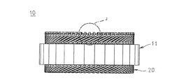
- FIG. 1 is a half sectional view showing a rotating electrical machine according to Embodiment 1 of the present invention
- FIG. 2 is a perspective view showing a main part of the rotating electrical machine according to Embodiment 1 of the present invention
- FIG. 3 is an embodiment of the present invention.
- 4 is a perspective view showing an armature in a rotary electric machine according to Embodiment 1
- FIG. 4 is a perspective view showing an iron core block constituting the armature core in the rotary electric machine according to Embodiment 1 of the present invention
- FIG. FIG. 6 is a perspective view showing a coil constituting the armature winding in the rotary electric machine according to the first embodiment
- FIG. 6 shows the first and third coils constituting the armature winding in the rotary electric machine according to the first embodiment of the present invention.
- FIG. 7 is an end view seen from the end side
- FIG. 7 is a front view showing a coil constituting the armature winding in the rotary electric machine according to Embodiment 1 of the present invention
- FIG. 8 is a rotation according to Embodiment 1 of the present invention.
- the slot-housed state is a fragmentary cross-sectional view schematically showing.
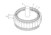
- the rotating electrical machine 100 is fixed to the housing 1 having the bottomed cylindrical frame 2 and the end plate 3 that closes the opening of the frame 2 and the cylindrical portion of the frame 2 in an internally fitted state.
- An armature 10 and a rotor fixed to a rotary shaft 6 rotatably supported on a bottom portion and an end plate 3 of the frame 2 via a bearing 4 and rotatably disposed on the inner peripheral side of the armature 10. 5 is provided.
- the rotor 5 is fixed to a rotor shaft 6 inserted through the shaft center position, and the rotor core 5 is embedded in the outer peripheral surface side of the rotor core 7 and arranged at an equal pitch in the circumferential direction to constitute a magnetic pole.
- the rotor 5 is not limited to a permanent magnet type rotor, and a squirrel-cage rotor in which a non-insulated rotor conductor is housed in a slot of a rotor core and both sides are short-circuited by a short-circuit ring, or an insulated conductor. You may use the winding-type rotor which attached the wire to the slot of the rotor core.
- the armature 10 includes an armature core 11, an armature winding 20 attached to the armature core 11, a slot cell 14 attached to a slot 13 of the armature core 11, It has.
- the armature winding 20 is configured by connecting a plurality of coils 21 mounted on the armature core 11.
- the slot cell 14 is formed in a U shape by bending a rectangular sheet made by, for example, sandwiching a polyimide film between meta-aramid fibers, inserted into the slot 13, and the armature core 11 and the armature winding. 20 is electrically isolated.
- the number of poles of the rotor 5 is 10
- the number of slots of the armature core 11 is 60
- the armature winding 20 is a three-phase winding. That is, the slots 13 are formed in the armature core 11 at a rate of two per phase per phase.
- the iron core block 12 is obtained by dividing an annular armature iron core 11 into 30 equal parts in the circumferential direction, and is manufactured by laminating and integrating a plurality of electromagnetic steel plates, and has a core back having a circular arc cross section. A portion 12a and two teeth 12b protruding radially inward from the inner peripheral wall surface of the core back portion 12a are provided. Then, the armature core 11 has the teeth 12b facing inward in the radial direction, the side surfaces in the circumferential direction of the core back portion 12a are butted together, and the 30 core blocks 12 are arranged and integrated in the circumferential direction. It is configured in an annular shape.
- the slots 13 constituted by the iron core blocks 12 adjacent in the circumferential direction are arranged at an equiangular pitch in the circumferential direction so as to open to the inner circumferential side.
- the teeth 12b are formed in a tapered shape in which the circumferential width gradually narrows inward in the radial direction, and the cross section perpendicular to the axial direction of the armature core 11 of the slot 13 is rectangular.
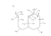
- the coil 21 constituting the armature winding 20 has a diameter d made of, for example, a continuous copper wire or aluminum wire that is insulation-coated with enamel resin and has no connection portion.
- a conductor wire having a circular cross section is wound into a ⁇ shape.
- the coil 21 has three rows arranged at six-slot angular intervals, and the lengths of the first, second, third, and fourth straight portions 21a, 21b, 21c, 21d, and the first and second straight portions 21a, 21b
- a first coil end portion 21e that connects the other ends in the vertical direction
- a second coil end portion 21f that connects the first ends in the length direction of the second and third straight portions 21b and 21c
- a third and a fourth A third coil end portion 21g connecting the other ends in the length direction of the straight portions 21c and 21d
- a first coil terminal 21h extending from one end in the length direction of the first straight portion 21a
- a second coil terminal 21j extending from one end in the length direction.
- the 6-slot angular interval is an interval between the slot centers of the slots 13 located on both sides of the six teeth 12b that are continuous in the circumferential direction, and corresponds to one magnetic pole pitch.
- the storage positions of the conductor wires stored in the slots 13 are defined as the first layer, the second layer, the third layer, and the fourth layer from the inner diameter side for convenience.
- 1, 2,..., 12, 13 are slot numbers assigned to the slots 13 in the order of arrangement in the circumferential direction.
- the first to third coil end portions 21e, 21f, and 21g are shown by straight lines for convenience.
- the first straight portion 21a is stored in the first layer in the first slot 13, and the second and fourth straight portions 21b and 21d are stored in the second and fourth layers in the seventh slot 13.
- Three straight portions 21 c are stored in the third layer in the thirteenth slot 13.
- the first, second, third, and fourth straight portions 21a, 21b, 21c, and 21d are arranged in three rows with an interval of 6 slots.
- the first coil end portion 21e extending from the first layer in the first slot 13 to the other axial end side of the armature core 11 maintains the radial position, and has a constant inclination on one side in the circumferential direction. Extending outward in the axial direction, displaced by d inward in the radial direction at the center (top), and then maintaining the radial position with a reverse inclination, extending in the circumferential direction and axially inward, Enter the second layer in the seventh slot 13.
- the second coil end portion 21f extending from the second layer in the seventh slot 13 to one end side in the axial direction of the armature core 11 maintains the radial position, and has a constant inclination on one side in the circumferential direction. It extends outward in the direction, is displaced inward in the radial direction by a central portion (top), and then is displaced in the radial direction by maintaining the radial position with a reverse inclination, and extends inward in the circumferential direction and 13 in the axial direction.
- the third layer in the numbered slot 13 is entered.
- the third coil end portion 21g extending from the third layer in the thirteenth slot 13 to the other axial end side of the armature core 11 maintains the radial position, and has a constant inclination on the other side in the circumferential direction. Extending outward in the axial direction, displaced by d inward in the radial direction at the center (top), and then maintaining the radial position with a reverse inclination, extending in the other circumferential direction and inward in the axial direction, The fourth layer in the seventh slot 13 is entered.
- the first to third coil end portions 21e, 21f, and 21g have a crank portion that is displaced in the radial direction by the width d of the conductor wire at the top. Further, the first to third coil end portions 21e, 21f, 21g and the first and second coil terminals 21h, 21j are crushed in the radial direction by a conductor wire having a circular cross section, and the radial thickness is d ′ (however, d ' ⁇ D), formed in a cross-sectional shape in which the axial thickness is d ′′ (where d ′′> d).
- the first coil terminal 21h extending from the first layer in the first slot 13 toward one end in the axial direction of the armature core 11 is bent by the first bending portion 21n to maintain the radial position and keep constant.
- the second bending portion 21m is bent in parallel with the axial direction of the armature core 11 and extends outward in the axial direction.
- the second coil terminal 21j extending from the fourth layer in the seventh slot 13 to the one end side in the axial direction of the armature core 11 is bent at the third bending portion 21p to maintain the radial position and keep constant.
- the first bending portion 21o bends in parallel with the axial direction of the armature core 11 and extends outward in the axial direction.
- the first and second coil terminals 21h and 21j are connected to the other coil 21, the power feeding unit, the neutral point, and the like on the tip side of the second and fourth bending portions 21m and 21o. Therefore, the insulating film is peeled off at the tip end sides of the second and fourth bent portions 21m, 21o of the first and second coil terminals 21h, 21j, and the circumferential width is e (where e ⁇ d ′′). It has become.
- FIGS. 9 is a perspective view showing an armature winding in the rotary electric machine according to Embodiment 1 of the present invention
- FIG. 10 is an insulating paper in the coil end of the armature winding in the rotary electric machine according to Embodiment 1 of the present invention
- FIG. 11 is a cross-sectional view schematically showing a state in which insulating paper is installed in the coil end of the armature winding in the rotary electric machine according to Embodiment 1 of the present invention
- FIG. 13 is a diagram for explaining a method of mounting an iron core block on an armature winding in a rotary electric machine according to Embodiment 1 of the present invention, and FIG. 13 shows an iron core block in the armature winding in the rotary electric machine according to Embodiment 1 of the present invention.
- FIG. 14 is a cross-sectional view schematically showing a state where an iron core block is attached to an armature winding in the rotary electric machine according to Embodiment 1 of the present invention, and FIG. According to Form 1
- FIG. 16 is a side view showing the outer diameter side insulating paper in the rotating electric machine according to the first embodiment of the present invention
- FIG. 17 is the first embodiment of the present invention.
- FIG. 18 is an enlarged view of portion A of FIG.
- FIG. 19 is a front view of the inner diameter side insulating paper in the rotating electric machine according to Embodiment 1 of the present invention
- FIG. FIG. 21 is a side view showing the inner diameter side insulating paper in the rotary electric machine according to Embodiment 1 of the present invention
- FIG. 21 is a perspective view showing the inner diameter side insulating paper in the rotary electric machine according to Embodiment 1 of the present invention
- FIG. 23 is an enlarged view of a portion B of FIG. 19, and FIG. 23 is a perspective view for explaining a method of attaching outer diameter side and inner diameter side insulating paper to the armature winding of the armature in the rotary electric machine according to Embodiment 1 of the present invention.
- FIG. 25 is a sectional view schematically showing the armature in the rotary electric machine according to Embodiment 1 of the present invention
- FIG. 25 The end view which looked at the armature with which the outer diameter side in the rotary electric machine concerning Embodiment 1 and the inner diameter side insulating paper were attached was seen from the axial direction one end side
- Drawing 27 in the rotary electric machine concerning Embodiment 1 of this invention FIG. 28 is an enlarged view of the H portion of FIG. 26, and
- FIG. 29 is an enlarged view of the J portion of FIG. 27.
- the armature winding 20 is shown by only the first to fourth straight portions 21a, 21b, 21c, and 21d.
- a bent portion unformed coil (not shown) in which the first to fourth bent portions 21n, 21m, 21p, 21o are not formed is manufactured.
- the first coil terminal 21h protrudes in the length direction of the first straight portion 21a
- the second coil terminal 21j protrudes in the length direction of the fourth straight portion 21d.
- 60 winding unassembled coils 1 are arranged at a 1-slot pitch in the circumferential direction to produce a winding assembly (not shown).
- the second coil end portions 21f are arranged in a row at a slot pitch in the circumferential direction.
- the first coil terminals 21h are arranged in one row at a one-slot pitch in the circumferential direction on the outer diameter side of the row of second coil end portions 21f.
- the second coil terminals 21j are arranged in one row at a slot pitch in the circumferential direction on the inner diameter side of the row of the second coil end portions 21f.
- the first coil end portions 21e are arranged in a row at a slot pitch in the circumferential direction.
- the third coil end portions 21g are arranged on the inner diameter side in the row of the first coil end portions 21e and in a row at a slot pitch in the circumferential direction.
- the row of the first coil end portions 21e and the row of the third coil end portions 21g are arranged in two layers in the radial direction on the other axial end side of the winding assembly.
- the first coil terminals 21h arranged in the circumferential direction are twisted to the other circumferential side, and the first bending portion 21n and the second bending portion 21m are turned into the first coil. Formed on the terminal 21h.
- the second coil terminal 21j arranged in the circumferential direction is twisted to one side in the circumferential direction by using a bending and twisting tool, and the third bending part 21p and the fourth bending part 21o are formed in the second coil terminal 21j.
- the armature winding 20 shown in FIG. 9 is produced.
- the winding assembly is configured in the same manner as the armature winding 20 except that the first to fourth bent portions 21n, 21m, 21p, and 21o are not formed.
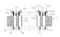
- the first insulating paper 151 made in an annular shape is inserted into the first coil end portion 21e from the one end side in the axial direction of the armature winding 20 through the first straight portion 21a and the second straight portion 21b.
- the third insulating paper 153 formed in an annular shape is inserted into the third coil end portion 21g from the one end side in the axial direction of the armature winding 20 through the third straight portion 21c and the fourth straight portion 21d.
- the second insulating paper 152 made in an annular shape is inserted into the second coil end portion 21f from the other end side in the axial direction of the armature winding 20 through the second straight portion 21b and the third straight portion 21c.
- the first to third insulating papers 151, 152, and 153 are attached to the armature winding 20 as shown in FIGS.
- the first to third insulating papers 151, 152, and 153 are rectangular strips cut from a sheet material such as polyimide, polyethylene terephthalate (PET), polyphenylene sulfide (PPS), and the middle of the short sides thereof. It is constructed by folding it in half and then rounding it into an annular shape.
- the average diameters of the first to third insulating papers 151, 152, and 153 attached to the armature winding 20 are ⁇ X1, ⁇ X2, and ⁇ X3.
- the slot cell 14 is mounted on each row of the first to fourth straight portions 21a, 21b, 21c, 21d of the armature winding 20.
- the 30 iron core blocks 12 position the teeth 12b radially outward between the adjacent first to fourth linear portions 21a, 21b, 21c, 21d. In order to achieve this, they are arranged at substantially equiangular pitch in the circumferential direction.
- the iron core blocks 12 arranged in the circumferential direction are moved inward in the radial direction. Thereby, each of the teeth 12b of the iron core block 12 is inserted between adjacent rows of the first to fourth linear portions 21a, 21b, 21c, 21d.
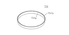
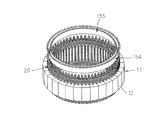
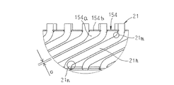
- the outer diameter side insulating paper 154 formed in an annular shape is arranged from the one end side in the axial direction of the armature winding 20 to the first coil terminal 21h row and the second coil end portion 21f row. Insert between.
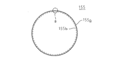
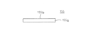
- the inner diameter side insulating paper 155 formed in an annular shape is inserted between the row of the second coil terminal 21 j and the row of the second coil end portion 21 f from one end side in the axial direction of the armature winding 20. In this way, the outer diameter side and inner diameter side insulating papers 154 and 155 are attached to the armature winding 20 as shown in FIGS.
- first and second coil terminals 21h and 21j are connected to each other, and the first and second coil terminals 21h and 21j are connected to the other coils 21 on the tip side of the second and fourth bent portions 21m and 21o. Connected to power feeding unit, neutral point, etc.
- the outer-diameter-side insulating paper 154 protrudes radially outward from one end side of the base 154 a and an annular base 154 a having a certain width.
- the inner diameter side insulating paper 155 protrudes radially inward from one end of the base portion 155a and an annular base portion 155a having a certain width.
- the outer diameter side and inner diameter side insulating papers 154 and 155 are made of an insulating sheet material such as polyimide, polyethylene terephthalate (PET), polyphenylene sulfide (PPS).
- the base portions 154a and 155a are produced by rounding a band-shaped insulating sheet cut out from the insulating sheet material into an annular shape. Produced.
- the width D of the slit 154c and the width E of the slit 155c are the widths of the tip portions of the first and second coil terminals 21h and 21j from the viewpoint of improving the mounting properties of the outer diameter side and inner diameter side insulating papers 154 and 155. e or more is desirable.
- the base 154a is the outer diameter side insulating paper base
- the protrusion 154b is the outer diameter side insulating paper protrusion
- the base 155a is the inner diameter side insulating paper base
- the protrusion 155b is the inner diameter side insulating paper protrusion.
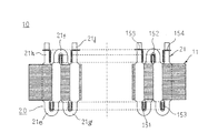
- the outer diameter side insulating paper 154 is inserted axially outward from the second bent portion 21m between the tip portions of the adjacent first coil terminals 21h through the protruding portion 154b.
- the base portion 154a is located between the row of the first coil terminals 21h and the row of the second coil end portions 21f.
- the inner diameter side insulating paper 155 is inserted axially outwardly from the fourth bent portion 21o between the tip portions of the adjacent second coil terminals 21j in the inner diameter side insulating paper 155, and the base portion 155a is arranged in the row of the second coil terminals 21j. And the second coil end portion 21f.
- the outer diameter side insulating paper 154 includes an annular base 154a disposed between the row of the first coil terminals 21h and the row of the second coil end portions 21f, respectively.
- a protrusion 154b inserted axially outward from the second bent portion 21m between the distal end portions of the adjacent first coil terminals 21h projecting radially outward from the axially outward end of the base portion 154a; It is equipped with.
- the inner diameter side insulating paper 155 includes an annular base portion 155a disposed between the row of the second coil terminals 21j and the row of the second coil end portions 21f, and an axially outer side of the base portion 155a.
- a protrusion 155b that protrudes radially inward from the other end and is inserted axially outward from the fourth bending portion 21o between the tips of the adjacent second coil terminals 21j.
- the first and third bent portions 21n and 22p and the second and second bent portions 21h and 21j of the bent portion unformed coil mounted on the armature core 11 are bent and bent using the bending and twisting tool.
- the outer diameter side and inner diameter side insulating papers 154 and 155 can be attached to the armature winding 20 from one end side in the axial direction.
- the bending stress due to the bending and twisting process of the first and second coil terminals 21h and 21j does not act on the outer diameter side and inner diameter side insulating papers 154 and 155. Therefore, the outer and inner diameter side insulating papers 154 and 155 are twisted, and the connecting portions between the projecting portions 154b and 155b and the base portions 154a and 155a are not damaged, or the base portions 154a and 155a are not deformed. Therefore, the rotary electric machine 100 can be applied to a use in which a high voltage is used.
- the outer diameter side and inner diameter side insulating papers 154 and 155 are rotated in the circumferential direction. However, if it is not inserted in the axial direction, the protrusions 154b and 155b interfere with the second bent portion 21m and the fourth bent portion 21o. According to the configuration of the present invention, since the radial protrusions 154b and 155b are on the outer side in the axial direction of the second bent portion 21m and the fourth bent portion 21o, the outer diameter side and inner diameter side insulating papers 154 and 155 are arranged in the axial direction. The projections 154b and 155b can be inserted without interfering with the second bent portion 21m and the fourth bent portion 21o, and the manufacturing cost can be reduced.
- first and third bent portions 21n and 22p and the second and fourth bent portions 21m and 21o are formed on the first and second coil terminals 21h and 21j of the bent portion unformed coils attached to the armature core 11.
- the bending and twisting devices for the first and second coil terminals 21h and 21j do not require the holding / positioning mechanism for the outer and inner diameter insulating papers 154 and 155, and the cost of the device can be reduced.
- the protruding portion 154b is inserted axially outward from the second bent portion 21m between the tip portions of the adjacent first coil terminals 21h. Therefore, the protrusion 154b comes into contact with the distal end side of the first coil terminal 21h, and movement of the outer diameter side insulating paper 154 in the circumferential direction is restricted. Further, the protrusion 154b comes into contact with the second bending portion 21m of the first coil terminal 21h, and movement toward the armature core 11, that is, movement in the axial direction is restricted. Thereby, the movement of the outer diameter side insulating paper 154 in the circumferential direction and the axial direction is restricted.
- the inner diameter side insulating paper 155 is moved in the circumferential direction and the axial direction. Be regulated. Therefore, in the connection processing of the first and second coil terminals 21h and 21j, the holding mechanism for the outer diameter side and inner diameter side insulating papers 154 and 155 is not required, the cost of the equipment is reduced, and the productivity is increased. .
- the protrusions 154b and 155b are inserted between the front ends of the first and second coil terminals 21h and 21j adjacent to each other, the gap between the front ends of the first and second coil terminals 21h and 21j
- the circumferential width of 154b and 155b can be maintained. Therefore, as shown in FIG. 29, the inclined portion located between the first and third bent portions 21n, 21p of the first and second coil terminals 21h, 21j and the second and fourth bent portions 21m, 21o. A gap G between them is secured. Thereby, the insulation distance in the circumferential direction of the 1st and 2nd coil terminals 21h and 21j is ensured, and electrical insulation is improved.
- the base portion 154a is disposed between the row of the first coil terminals 21h and the row of the second coil end portions 21f, and the base portion 155a is formed between the row of the second coil terminals 21j and the row of the second coil end portions 21f. Since it is arrange
- outer diameter side and inner diameter side insulating papers 154 and 155 are made of an insulating sheet material, manufacturing becomes easy and cost reduction is achieved, and the outer diameter side and inner diameter side insulating papers 154 and 155 are made thinner. Thus, the coil end can be reduced in size.
- first to third insulating papers 151, 152, 153 are inserted into the first to third coil end portions 21e, 21f, 21g, the first to third coil end portions 21e, 21f, 21g The electrical insulation at the coil end to be constructed is improved.
- the outer diameter side and inner diameter side insulating papers are arranged in one layer in the radial direction, but in addition to the outer diameter side and inner diameter side insulating paper, one sheet or a plurality of sheets are provided.
- An annular base may be provided.
- the base portion is arranged in two layers or three or more layers in the radial direction, and electrical insulation is improved.
- the possibility that the same portion of the other base portion is broken is very low, electrical insulation can be ensured, and reliability with respect to electrical insulation is enhanced.
- the axially inward ends of a plurality of bases provided side by side are connected by a bridge, the number of parts is reduced and productivity is improved.
- the bending and twisting steps of the first and second coil terminals of the bending portion unformed coils are performed.
- the bending and twisting process of the first and second coil ends of the bending portion unformed coil may be performed, and the bending of the first and second coil ends may be performed.
- the twisting process may be performed within the coil forming process.
- FIG. FIG. 30 is a cross-sectional view schematically showing an armature in a rotary electric machine according to Embodiment 2 of the present invention.
- the outer diameter side insulating paper 154A is a resin molded body in which an annular base 154a ′ and a protrusion 154b ′ are integrally formed.
- the inner diameter side insulating paper 155A is a resin molded body in which an annular base 155a ′ and a protrusion 155b ′ are integrally formed.
- Other configurations are the same as those in the first embodiment.
- the thickness is increased in order to ensure the fluidity of the resin during resin molding. Therefore, the insulation distance can be reliably ensured, the electrical insulation can be improved, the risk of the outer diameter side and inner diameter side insulating papers 154A and 155A being broken can be reduced, and the reliability with respect to the electrical insulation can be increased.
- the outer diameter side and inner diameter side insulating paper is made of a resin molded body, a complicated mold is required, and in order to ensure the fluidity of the resin at the time of resin molding, the thickness is more than necessary. It becomes the thickness of. Therefore, from the viewpoint of cost reduction and miniaturization, it is desirable to produce the outer diameter side and inner diameter side insulating paper with insulating sheets.
- FIG. 31 is a cross-sectional view schematically showing an armature in a rotary electric machine according to Embodiment 3 of the present invention.
- annular base portion 154a "of the outer diameter side insulating paper 154B is folded in two in the axial direction at the central portion in the axial direction to form two layers in the radial direction.
- An annular base portion 155a "of 155B is folded in two in the axial direction at the central portion in the width direction to form two layers in the radial direction.
- Other configurations are the same as those in the first embodiment.
- the base portions 154a "and 155a" are folded in half at the axial central portion to form two layers in the radial direction, the rigidity of the outer diameter side and inner diameter side insulating papers 154B and 155B Is increased. Therefore, the outer diameter side and inner diameter side insulating papers 154B and 155B can be easily mounted on the armature winding 20, and the outer diameter side and inner diameter side insulating paper 154B and 155B seats when the armature winding 20 is mounted. Occurrence of bending and wrinkles is suppressed, and productivity is increased.
- an insulation distance in the radial direction between the first coil terminal 21h and the second coil end portion 21f is ensured, and an insulation distance in the radial direction between the second coil end 21j and the second coil end portion 21f is secured. And electrical insulation is enhanced. Furthermore, even if one of the base portions 154a ′′ and 155a ′′ is broken, the electrical insulation is ensured by the other, so that the reliability with respect to the electrical insulation can be improved.
- FIG. 32 is a cross-sectional view schematically showing an armature in a rotary electric machine according to Embodiment 4 of the present invention.
- the first to third coil end portions 21e ′, 21f ′, 21g ′ and the first and second coil terminals 21h ′, 21j ′ are changed from the first to fourth linear portions 21a, 21b, 21c, 21d.
- only one surface in the radial direction is deformed.
- Other configurations are the same as those in the third embodiment.
- the first to third coil end portions 21e ′, 21f ′, 21g ′ and the first and second coil terminals 21h ′, 21j ′ of the coil 21A are connected to the first to fourth linear portions 21a, With respect to 21b, 21c, and 21d, only one surface in the radial direction is deformed. As a result, the radial gaps in the first to third coil end portions 21e ′, 21f ′, 21g ′ into which the first to third insulating papers 151, 152, 153 are inserted are widened. Interphase insulation can be improved without enlarging the directional dimension.
- FIG. 33 is a perspective view showing coils constituting the armature winding in the rotary electric machine according to Embodiment 5 of the present invention
- FIG. 34 constitutes the armature winding in the rotary electric machine according to Embodiment 5 of the present invention.
- FIG. 35 is an end view of the coil viewed from the first and second coil terminal sides
- FIG. 35 is a front view showing the coil constituting the armature winding in the rotary electric machine according to Embodiment 5 of the present invention
- FIG. 37 is a front view showing insulating paper in a rotating electrical machine according to Embodiment 5
- FIG. 37 is a side view showing insulating paper in the rotating electrical machine according to Embodiment 5 of the present invention
- FIG. 39 is a perspective view showing the insulating paper in the rotating electrical machine
- FIG. 39 is a front view of the principal part showing the insulating paper in the rotating electrical machine according to Embodiment 5 of the present invention
- FIG. 40 is a cross-sectional view taken along arrow XXX-XXXX in FIG. Is the implementation of this invention
- 42 is an end view of the armature in the rotary electric machine according to the fifth embodiment when viewed from one end side in the axial direction
- FIG. 42 is a side view showing the armature in the rotary electric machine according to the fifth embodiment of the present invention
- FIG. FIG. 44 is a cross-sectional view schematically showing an armature in a rotary electric machine according to Embodiment 5 of the present invention.
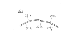
- the coil 221 is formed, for example, by forming a conductor wire having a circular cross section having a diameter d made of a continuous copper wire or an aluminum wire, which is insulation-coated with enamel resin and has no connection portion, into a U shape. Produced. Note that the coil 221 may be manufactured using a conductor wire having a rectangular cross section.
- the coil 221 connects the first and second straight portions 221 a and 221 b that are separated by an angle of 6 slots and the other ends of the first and second straight portions 221 a and 221 b.
- a first coil end portion 221e, a first coil terminal 221h protruding from one end of the first straight line portion 221a, and a second coil terminal 221j protruding from one end of the second straight line portion 221b are provided.
- the first straight portion 221a is housed in the first layer in one slot, and the second straight portion 221b is in the second layer in the slot having a six-slot angular interval from one slot in the circumferential direction. It is made to be stored in That is, the first coil end portion 221e maintains a radial position from the other end of the first linear portion 221a, extends at a certain inclination in the circumferential direction and axially outward, and at the central portion (top portion). It is displaced radially inward by the radial width d of the conductor wire, and thereafter, with a reverse inclination, maintains the radial position and extends inward in the circumferential direction and inward in the axial direction. It is made to reach the end.
- first coil terminal 221h extending from one end of the first straight portion 221a is bent at the first bending portion 221n, maintains the radial position, and has a constant inclination on the other side in the circumferential direction and outside in the axial direction.
- the second bent portion 221m is bent in parallel with the axial direction and extends outward in the axial direction.
- the second coil terminal 221j extending from one end of the second straight part 221b is bent by the third bending part 221p, maintains the radial position, and moves circumferentially to one side and axially outward with a certain inclination.
- the fourth bent portion 221o is bent in parallel with the axial direction and extends outward in the axial direction.
- first and second coil terminals 221h and 221j are connected to other coils 221, a power feeding unit, a neutral point, and the like on the tip side of the second and fourth bending portions 221m and 221o.
- the first coil end portion 221e and the first and second coil terminals 221h and 221j are formed by crushing a conductor wire having a circular cross section in the radial direction to have a radial thickness d ′ (where d ′ ⁇ d), and an axial direction. It is formed in a cross-sectional shape having a thickness d ′′ (where d ′′> d).
- the insulating film is peeled off from the tip side of the second and fourth bent portions 221m, 221o of the first and second coil terminals 221h, 221j, and the circumferential width is e (where e ⁇ d ′′). Yes.
- the coil 221 configured in this way includes a first layer and a second layer in one slot in which the first and second linear portions 221a and 221b are spaced apart by six slots, respectively.
- the first insulating paper 151 is arranged in one row in the circumferential direction from the one end side in the axial direction of the armature core 11 through the row of the first straight portions 221a and the rows of the second straight portions 221b.
- the first coil end portion 221e is mounted.
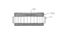
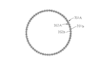
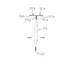
- the outer diameter side insulating paper 351 and the inner diameter side insulating paper 352 are mounted between the first coil terminal 221 h and the second coil terminal 221 j from one axial end side of the armature core 11.
- the outer diameter side and inner diameter side insulating papers 351 and 352 are formed in an annular shape from an insulating sheet material such as polyimide, polyethylene terephthalate (PET), polyphenylene sulfide (PPS).
- the base portions 351a and 352a are produced by rounding a band-shaped insulating sheet cut out from the insulating sheet material into an annular shape, and the protruding portions 351b and 352b protrude from the axially outer ends of the base portions 351a and 352a.
- the protruding portion is produced by bending the base portion radially outward or radially inward. Further, the ends of the base portions 351 a and 352 a on the inner side in the axial direction are connected by a bridge portion 353.
- the base 351a is the outer diameter side insulating paper base
- the protrusion 351b is the outer diameter side insulating paper protrusion
- the base 352a is the inner diameter side insulating paper base
- the protrusion 352b is the inner diameter side insulating paper protrusion.
- the width J of the slit 351c and the width K of the slit 352c are the widths of the front end portions of the first and second coil terminals 221h and 221j from the viewpoint of improving the mounting properties of the outer and inner diameter side insulating papers 351 and 352. e or more is desirable.
- the outer-diameter-side insulating paper 351 configured in this way is inserted in the protruding portion 351b axially outward from the second bent portion 221m between the tip portions of the adjacent first coil terminals 221h, and the base portion 351a is the first.
- the inner diameter side insulating paper 352 is inserted axially outwardly from the fourth bent portion 221o between the tip portions of the adjacent second coil terminals 221j in the inner diameter side insulating paper 352, and the base portion 351a is arranged in the row of the second coil terminals 221j.
- the outer diameter side insulating paper 351 has an annular base 351a disposed along the row of the first coil terminals 221h on the inner diameter side of the row of the first coil terminals 221h.
- a protrusion 351b inserted axially outward from the second bent portion 221m between the distal ends of the first coil terminals 221h that protrude radially outward from the axially outward end of the base 351a; It has.
- the inner diameter side insulating paper 351 includes an annular base portion 352a disposed along the row of second coil terminals 221j on the outer diameter side of the row of second coil terminals 221j, and the shaft of the base portion 352a.
- the base portion 351a of the outer diameter side insulating paper 351 and the base portion 352a of the inner diameter side insulating paper 352 are connected by the bridge portion 353. Therefore, since the outer diameter side and inner diameter side insulating papers 352 and 352 become one component, the number of components is reduced and productivity is increased. In addition, since the rigidity of the base portions 351a and 352a is increased, the outer diameter side and inner diameter side insulating paper 352 and 352 can be easily mounted on the armature winding 20A, and the outer diameter when the armature winding 20A is mounted. The occurrence of buckling and wrinkling of the side and inner diameter side insulating papers 352 and 352 is suppressed, and the productivity is improved.
- the outer diameter side insulating paper and the inner diameter side insulating paper are integrated by connecting the base portion of the outer diameter side insulating paper and the base portion of the inner diameter side insulating paper with a bridge portion.
- the outer diameter side insulating paper and the inner diameter side insulating paper may be integrated by folding in half at the center in the axial direction.
- the armature core is formed by connecting 60 core blocks in an annular shape, and the armature core is laminated with, for example, an annular core piece punched out from an electromagnetic steel sheet. You may comprise with a single integrated iron core.
- FIG. 45 is a front view showing insulating paper in a rotary electric machine according to Embodiment 6 of the present invention
- FIG. 46 is a side view showing insulating paper in the rotary electric machine according to Embodiment 6 of the present invention
- FIG. 48 is a perspective view showing insulating paper in the rotating electrical machine according to the sixth embodiment
- FIG. 48 is a sectional view taken along the line XXXVIII-XXXVIII in FIG. 46
- FIG. 49 is a schematic diagram of the armature in the rotating electrical machine according to the sixth embodiment of the present invention.
- FIG. 45 is a front view showing insulating paper in a rotary electric machine according to Embodiment 6 of the present invention
- FIG. 46 is a side view showing insulating paper in the rotary electric machine according to Embodiment 6 of the present invention
- FIG. 48 is a perspective view showing insulating paper in the rotating electrical machine according to the sixth embodiment
- FIG. 48 is a sectional view taken along the line
- through holes 354 are formed so as to penetrate the base portions 351a ′ and 352a ′ of the outer diameter side and inner diameter side insulating papers 351A and 352A in the radial direction.
- Other configurations are the same as those in the fifth embodiment.
- the through hole 354 is formed so as to penetrate the base portions 351a ′ and 352a ′ of the outer diameter side and inner diameter side insulating papers 351A and 352A in the radial direction.
- a cooling medium such as cooling air or cooling oil flows in the radial direction through the through hole 354, and the cooling performance of the armature is improved.
- two through holes are formed in the outer diameter side and inner diameter side insulating paper bases.
- the number of through holes is not limited to two, and may be one or more. .
- the conductor wire is wound around a ⁇ -shaped coil pattern to produce a coil.
- the conductor wire is wound around a U-shaped coil pattern.
- the coil is not limited to a coil having a ⁇ -shaped or U-shaped coil pattern, and 2n straight portions (where n is an integer equal to or greater than 1) and 2n
- n is an integer equal to or greater than 1
- the first coil end of the coil is the outermost diameter in the slot. It suffices if the second end of the coil protrudes from the position in the axial direction and protrudes from the innermost diameter position in the slot toward the axial direction.
- a conductor wire is wound around a spiral coil pattern. Even a tortoiseshell shaped coil Yes.
Landscapes
- Engineering & Computer Science (AREA)
- Power Engineering (AREA)
- Manufacturing & Machinery (AREA)
- Insulation, Fastening Of Motor, Generator Windings (AREA)
- Manufacture Of Motors, Generators (AREA)
Abstract
Priority Applications (4)
| Application Number | Priority Date | Filing Date | Title |
|---|---|---|---|
| US15/307,286 US9705374B2 (en) | 2014-05-15 | 2015-04-28 | Rotary electric machine and a manufacturing method thereof |
| CN201580026536.3A CN106464054B (zh) | 2014-05-15 | 2015-04-28 | 旋转电机及其制造方法 |
| JP2016519205A JP6138360B2 (ja) | 2014-05-15 | 2015-04-28 | 回転電機およびその製造方法 |
| DE112015002276.7T DE112015002276B4 (de) | 2014-05-15 | 2015-04-28 | Drehende elektrische Maschine und Herstellungsverfahren für diese |
Applications Claiming Priority (2)
| Application Number | Priority Date | Filing Date | Title |
|---|---|---|---|
| JP2014-101585 | 2014-05-15 | ||
| JP2014101585 | 2014-05-15 |
Publications (1)
| Publication Number | Publication Date |
|---|---|
| WO2015174277A1 true WO2015174277A1 (fr) | 2015-11-19 |
Family
ID=54479819
Family Applications (1)
| Application Number | Title | Priority Date | Filing Date |
|---|---|---|---|
| PCT/JP2015/062826 Ceased WO2015174277A1 (fr) | 2014-05-15 | 2015-04-28 | Machine électrique tournante et son procédé de fabrication |
Country Status (5)
| Country | Link |
|---|---|
| US (1) | US9705374B2 (fr) |
| JP (1) | JP6138360B2 (fr) |
| CN (1) | CN106464054B (fr) |
| DE (1) | DE112015002276B4 (fr) |
| WO (1) | WO2015174277A1 (fr) |
Cited By (2)
| Publication number | Priority date | Publication date | Assignee | Title |
|---|---|---|---|---|
| WO2018019969A1 (fr) * | 2016-07-27 | 2018-02-01 | Grob-Werke Gmbh & Co. Kg | Procédé d'insertion d'un papier isolant |
| JP2020048295A (ja) * | 2018-09-18 | 2020-03-26 | 本田技研工業株式会社 | シート状波巻コイル |
Families Citing this family (4)
| Publication number | Priority date | Publication date | Assignee | Title |
|---|---|---|---|---|
| JP6355816B2 (ja) * | 2015-02-26 | 2018-07-11 | 三菱電機株式会社 | 回転電機 |
| JP7044871B2 (ja) * | 2018-05-23 | 2022-03-30 | 日立Astemo株式会社 | 回転電機および回転電機の製造方法 |
| EP3836359B1 (fr) * | 2018-11-09 | 2026-04-22 | Aisin Corporation | Induit et procédé de production d'induit |
| CN114337015B (zh) * | 2021-12-31 | 2023-07-25 | 华中科技大学 | 一种具有定子浸油冷却结构的高功率密度电机 |
Citations (7)
| Publication number | Priority date | Publication date | Assignee | Title |
|---|---|---|---|---|
| JPS5762745A (en) * | 1980-10-01 | 1982-04-15 | Matsushita Electric Ind Co Ltd | Phase-to-phase insulation paper for motor |
| JPH07298530A (ja) * | 1994-04-28 | 1995-11-10 | Honda Motor Co Ltd | 多相ステータ |
| JP2001095186A (ja) * | 1999-09-20 | 2001-04-06 | Denso Corp | 導体セグメント接合型ステータコイルを有する回転電機 |
| JP2004032964A (ja) * | 2002-06-28 | 2004-01-29 | Toyota Motor Corp | コイル端部スペーサ、セグメント型電機子、セグメント整列方法、ならびにセグメント開放端部の捻り成形方法 |
| JP2011036093A (ja) * | 2009-08-05 | 2011-02-17 | Hitachi Automotive Systems Ltd | 回転電機 |
| JP2011139588A (ja) * | 2009-12-28 | 2011-07-14 | Hitachi Automotive Systems Ltd | 回転電機およびその製造方法 |
| WO2014034157A1 (fr) * | 2012-08-31 | 2014-03-06 | 三菱電機株式会社 | Machine électrique rotative et son procédé de fabrication |
Family Cites Families (4)
| Publication number | Priority date | Publication date | Assignee | Title |
|---|---|---|---|---|
| JP4396298B2 (ja) | 2004-02-06 | 2010-01-13 | 株式会社デンソー | 回転電機の巻線の製造方法 |
| JP2011234429A (ja) * | 2010-04-23 | 2011-11-17 | Toshiba Corp | 回転電機の相間絶縁紙及び回転電機 |
| JP5625733B2 (ja) | 2010-10-22 | 2014-11-19 | 株式会社明電舎 | 回転電機の相間絶縁紙 |
| JP5741555B2 (ja) * | 2012-11-07 | 2015-07-01 | 株式会社豊田自動織機 | 回転電機における相間絶縁シート、及び電動圧縮機 |
-
2015
- 2015-04-28 US US15/307,286 patent/US9705374B2/en not_active Expired - Fee Related
- 2015-04-28 CN CN201580026536.3A patent/CN106464054B/zh not_active Expired - Fee Related
- 2015-04-28 WO PCT/JP2015/062826 patent/WO2015174277A1/fr not_active Ceased
- 2015-04-28 DE DE112015002276.7T patent/DE112015002276B4/de not_active Expired - Fee Related
- 2015-04-28 JP JP2016519205A patent/JP6138360B2/ja not_active Expired - Fee Related
Patent Citations (7)
| Publication number | Priority date | Publication date | Assignee | Title |
|---|---|---|---|---|
| JPS5762745A (en) * | 1980-10-01 | 1982-04-15 | Matsushita Electric Ind Co Ltd | Phase-to-phase insulation paper for motor |
| JPH07298530A (ja) * | 1994-04-28 | 1995-11-10 | Honda Motor Co Ltd | 多相ステータ |
| JP2001095186A (ja) * | 1999-09-20 | 2001-04-06 | Denso Corp | 導体セグメント接合型ステータコイルを有する回転電機 |
| JP2004032964A (ja) * | 2002-06-28 | 2004-01-29 | Toyota Motor Corp | コイル端部スペーサ、セグメント型電機子、セグメント整列方法、ならびにセグメント開放端部の捻り成形方法 |
| JP2011036093A (ja) * | 2009-08-05 | 2011-02-17 | Hitachi Automotive Systems Ltd | 回転電機 |
| JP2011139588A (ja) * | 2009-12-28 | 2011-07-14 | Hitachi Automotive Systems Ltd | 回転電機およびその製造方法 |
| WO2014034157A1 (fr) * | 2012-08-31 | 2014-03-06 | 三菱電機株式会社 | Machine électrique rotative et son procédé de fabrication |
Cited By (3)
| Publication number | Priority date | Publication date | Assignee | Title |
|---|---|---|---|---|
| WO2018019969A1 (fr) * | 2016-07-27 | 2018-02-01 | Grob-Werke Gmbh & Co. Kg | Procédé d'insertion d'un papier isolant |
| JP2020048295A (ja) * | 2018-09-18 | 2020-03-26 | 本田技研工業株式会社 | シート状波巻コイル |
| JP6990638B2 (ja) | 2018-09-18 | 2022-01-12 | 本田技研工業株式会社 | シート状波巻コイル |
Also Published As
| Publication number | Publication date |
|---|---|
| JPWO2015174277A1 (ja) | 2017-04-20 |
| US9705374B2 (en) | 2017-07-11 |
| US20170047808A1 (en) | 2017-02-16 |
| JP6138360B2 (ja) | 2017-05-31 |
| CN106464054A (zh) | 2017-02-22 |
| DE112015002276B4 (de) | 2023-11-16 |
| DE112015002276T5 (de) | 2017-02-09 |
| CN106464054B (zh) | 2019-05-28 |
Similar Documents
| Publication | Publication Date | Title |
|---|---|---|
| US8836186B2 (en) | Bus bar device, stator, motor and manufacturing method for stator | |
| JP6138360B2 (ja) | 回転電機およびその製造方法 | |
| US8432082B2 (en) | Armature and motor | |
| JP5314908B2 (ja) | 回転電機の固定子および回転電機 | |
| CN109075668B (zh) | 电枢的制造方法、旋转电机的制造方法、电枢、旋转电机及电枢的制造装置 | |
| JP5471389B2 (ja) | 回転電機の固定子 | |
| EP3176912A1 (fr) | Stator et machine tournante | |
| JP6165260B2 (ja) | 回転電機 | |
| WO2014034157A1 (fr) | Machine électrique rotative et son procédé de fabrication | |
| US10320256B2 (en) | Method for manufacturing stator of rotary electric machine including a cassette coil | |
| JP6341288B2 (ja) | ステータ組立方法及びステータ | |
| WO2014050164A1 (fr) | Machine électrique | |
| WO2012169059A1 (fr) | Stator de machine électrique tournante, procédé de fabrication d'un stator de machine électrique tournante, et machine électrique tournante | |
| JP2016049007A (ja) | 回転電機 | |
| JP7342654B2 (ja) | 回転電機 | |
| JP5987161B2 (ja) | 電動機およびそれを搭載した天井扇 | |
| JP6210705B2 (ja) | 回転電機およびそれに用いられる固定子 | |
| JP6093266B2 (ja) | セグメントコイル及びステータ | |
| JP2014057462A (ja) | 回転電機の固定子 | |
| JP6080964B2 (ja) | 回転電機の固定子 | |
| JP2013005652A (ja) | 回転電機及び集中巻コイル | |
| JP6394542B2 (ja) | 回転電機ステータ | |
| JP2015107029A (ja) | 電機子及び回転電機 | |
| JP2011160572A (ja) | 回転電機のステータの製造方法 | |
| CN105052014A (zh) | 电动机及其制造方法 |
Legal Events
| Date | Code | Title | Description |
|---|---|---|---|
| 121 | Ep: the epo has been informed by wipo that ep was designated in this application |
Ref document number: 15793296 Country of ref document: EP Kind code of ref document: A1 |
|
| ENP | Entry into the national phase |
Ref document number: 2016519205 Country of ref document: JP Kind code of ref document: A |
|
| WWE | Wipo information: entry into national phase |
Ref document number: 15307286 Country of ref document: US |
|
| WWE | Wipo information: entry into national phase |
Ref document number: 112015002276 Country of ref document: DE |
|
| 122 | Ep: pct application non-entry in european phase |
Ref document number: 15793296 Country of ref document: EP Kind code of ref document: A1 |