WO2012169122A1 - Cellule alcaline - Google Patents
Cellule alcaline Download PDFInfo
- Publication number
- WO2012169122A1 WO2012169122A1 PCT/JP2012/003232 JP2012003232W WO2012169122A1 WO 2012169122 A1 WO2012169122 A1 WO 2012169122A1 JP 2012003232 W JP2012003232 W JP 2012003232W WO 2012169122 A1 WO2012169122 A1 WO 2012169122A1
- Authority
- WO
- WIPO (PCT)
- Prior art keywords
- sealing plate
- negative electrode
- separator
- gasket
- alkaline battery
- Prior art date
- Legal status (The legal status is an assumption and is not a legal conclusion. Google has not performed a legal analysis and makes no representation as to the accuracy of the status listed.)
- Ceased
Links
Images


Classifications
-
- H—ELECTRICITY
- H01—ELECTRIC ELEMENTS
- H01M—PROCESSES OR MEANS, e.g. BATTERIES, FOR THE DIRECT CONVERSION OF CHEMICAL ENERGY INTO ELECTRICAL ENERGY
- H01M6/00—Primary cells; Manufacture thereof
- H01M6/04—Cells with aqueous electrolyte
- H01M6/06—Dry cells, i.e. cells wherein the electrolyte is rendered non-fluid
- H01M6/08—Dry cells, i.e. cells wherein the electrolyte is rendered non-fluid with cup-shaped electrodes
- H01M6/085—Dry cells, i.e. cells wherein the electrolyte is rendered non-fluid with cup-shaped electrodes of the reversed type, i.e. anode in the centre
-
- H—ELECTRICITY
- H01—ELECTRIC ELEMENTS
- H01M—PROCESSES OR MEANS, e.g. BATTERIES, FOR THE DIRECT CONVERSION OF CHEMICAL ENERGY INTO ELECTRICAL ENERGY
- H01M50/00—Constructional details or processes of manufacture of the non-active parts of electrochemical cells other than fuel cells, e.g. hybrid cells
- H01M50/40—Separators; Membranes; Diaphragms; Spacing elements inside cells
- H01M50/463—Separators, membranes or diaphragms characterised by their shape
- H01M50/469—Separators, membranes or diaphragms characterised by their shape tubular or cylindrical
-
- H—ELECTRICITY
- H01—ELECTRIC ELEMENTS
- H01M—PROCESSES OR MEANS, e.g. BATTERIES, FOR THE DIRECT CONVERSION OF CHEMICAL ENERGY INTO ELECTRICAL ENERGY
- H01M50/00—Constructional details or processes of manufacture of the non-active parts of electrochemical cells other than fuel cells, e.g. hybrid cells
- H01M50/10—Primary casings; Jackets or wrappings
- H01M50/102—Primary casings; Jackets or wrappings characterised by their shape or physical structure
- H01M50/107—Primary casings; Jackets or wrappings characterised by their shape or physical structure having curved cross-section, e.g. round or elliptic
-
- H—ELECTRICITY
- H01—ELECTRIC ELEMENTS
- H01M—PROCESSES OR MEANS, e.g. BATTERIES, FOR THE DIRECT CONVERSION OF CHEMICAL ENERGY INTO ELECTRICAL ENERGY
- H01M50/00—Constructional details or processes of manufacture of the non-active parts of electrochemical cells other than fuel cells, e.g. hybrid cells
- H01M50/10—Primary casings; Jackets or wrappings
- H01M50/147—Lids or covers
- H01M50/166—Lids or covers characterised by the methods of assembling casings with lids
- H01M50/167—Lids or covers characterised by the methods of assembling casings with lids by crimping
-
- H—ELECTRICITY
- H01—ELECTRIC ELEMENTS
- H01M—PROCESSES OR MEANS, e.g. BATTERIES, FOR THE DIRECT CONVERSION OF CHEMICAL ENERGY INTO ELECTRICAL ENERGY
- H01M50/00—Constructional details or processes of manufacture of the non-active parts of electrochemical cells other than fuel cells, e.g. hybrid cells
- H01M50/10—Primary casings; Jackets or wrappings
- H01M50/147—Lids or covers
- H01M50/166—Lids or covers characterised by the methods of assembling casings with lids
- H01M50/171—Lids or covers characterised by the methods of assembling casings with lids using adhesives or sealing agents
-
- Y—GENERAL TAGGING OF NEW TECHNOLOGICAL DEVELOPMENTS; GENERAL TAGGING OF CROSS-SECTIONAL TECHNOLOGIES SPANNING OVER SEVERAL SECTIONS OF THE IPC; TECHNICAL SUBJECTS COVERED BY FORMER USPC CROSS-REFERENCE ART COLLECTIONS [XRACs] AND DIGESTS
- Y02—TECHNOLOGIES OR APPLICATIONS FOR MITIGATION OR ADAPTATION AGAINST CLIMATE CHANGE
- Y02E—REDUCTION OF GREENHOUSE GAS [GHG] EMISSIONS, RELATED TO ENERGY GENERATION, TRANSMISSION OR DISTRIBUTION
- Y02E60/00—Enabling technologies; Technologies with a potential or indirect contribution to GHG emissions mitigation
- Y02E60/10—Energy storage using batteries
Definitions
- the present invention relates to a sealing structure for an alkaline battery.
- Patent Documents 1 and 2 describe an alkaline battery in which an opening of a battery case is sealed with a sealing plate via a ring-shaped gasket having an L-shaped or J-shaped cross section. In this way, by configuring the gasket in a ring shape, the volume occupied by the gasket is reduced, so that the capacity of the alkaline battery can be increased.
- the separator is in contact with the sealing plate through the gasket ring. Therefore, for example, when an impact is applied to an alkaline battery when it is dropped or transported, there is no support of the separator, so the active material of the negative electrode may get over the separator or break the separator. There is a possibility of causing an internal short circuit by contact with the positive electrode.
- the present invention solves such a problem, and its main object is to provide an alkaline battery having a ring-shaped gasket that does not cause an internal short circuit even when an external impact is applied.
- the present invention extends the lower part of the sealing plate radially inward in an alkaline battery in which the opening of the battery case is sealed with a sealing plate via a ring-shaped gasket.
- a structure in which a separator is in close contact with the end face of the gasket is adopted.
- the alkaline battery according to the present invention includes a hollow cylindrical positive electrode, a negative electrode filled in a hollow portion of the positive electrode, and a parator disposed between the positive electrode and the negative electrode, together with the electrolyte, a bottomed cylinder.
- Alkaline battery housed in a battery case the opening of the battery case is sealed with a sealing plate via a ring-shaped gasket, and the ring-shaped gasket is a peripheral portion of the battery case and the sealing plate
- a peripheral wall portion interposed between the outer peripheral portion and the outer extending portion extending radially inward from the peripheral wall portion, and from the peripheral wall portion opposite to the opening portion side of the battery case.
- the separator has an inner extending portion that extends radially inward, and the end of the separator is in close contact with the end surface of the inner extending portion on the radially inner side.
- the end surface of the separator is brought into close contact with the end surface in the radially inward direction of the inner extension portion of the gasket, so that the end surface serves as a support for the separator even when an external impact is applied to the battery.
- the action of the negative electrode active material overcoming the separator or breaking the separator can be suppressed.
- FIG. 1 is a half cross-sectional view illustrating a configuration of an alkaline battery according to an embodiment of the present invention. It is the partial half sectional view which showed the structure of the alkaline battery in other embodiment of this invention.
- (A)-(d) is the fragmentary sectional view which showed the structure of the gasket in other embodiment of this invention.
- FIG. 1 is a half sectional view showing a configuration of an AA alkaline battery (LR6 defined in JIS standard and IEC standard) in one embodiment of the present invention.
- a hollow cylindrical positive electrode 2, a negative electrode 3 filled in a hollow portion of the positive electrode 2, and a separator 4 disposed between the positive electrode 2 and the negative electrode 3 are present together with an electrolyte.
- the battery case 1 is accommodated in a bottom cylindrical shape.
- the opening of the battery case 1 is sealed with a sealing plate 7 via a ring-shaped gasket 5.
- the ring-shaped gasket 5 is located on the opening side of the battery case 1 and extends radially inward from the peripheral wall 5a interposed between the battery case 1 and the peripheral edge of the sealing plate 7 and the peripheral wall 5a.
- the outer extending portion 5b and the inner extending portion 5c extending from the peripheral wall portion 5a on the opposite side to the opening side of the battery case 1 and extending radially inward are provided.
- the edge part of the separator 4 is closely_contact
- “inward in the radial direction” refers to a direction from the periphery of the cylindrical battery case 1 toward the central axis J.
- the extended portions 5b and 5c of the gasket 5 refer to portions extending radially inward along the sealing plate 7 from the peripheral wall portion 5a, and the peripheral portion of the sealing plate 7 extends outward. It is dressed by the protruding portion 5b and the inner extending portion 5c. Thereby, when an impact is applied from the outside, the displacement of the gasket 5 can be suppressed, so that the support of the separator 4 by the end surface of the inner extension portion 5c can be further strengthened. In addition, since the volume occupied by the gasket 5 can be further reduced, the capacity of the alkaline battery can be further increased.
- the outer extending portion 5b and the inner extending portion 5c do not necessarily have to be in contact with the sealing plate 7.
- a hollow cylindrical battery case 1 serving as a positive electrode terminal and a positive electrode current collector is housed so that a hollow cylindrical positive electrode 2 is inscribed therein.
- the negative electrode 3 is disposed via a bottomed cylindrical separator 4.
- the opening of the battery case 1 is sealed by arranging a sealing plate 7 also serving as a negative electrode terminal via a gasket 5 and then bending the opening of the battery case 1 inward.
- the outer surface of the battery case 1 is covered with an exterior label 8.
- the material of the gasket 5 is not particularly limited, and can be obtained by injection molding a resin such as nylon, polypropylene, or polyethylene into a predetermined size and shape.
- the length (width) of the end face in the radially inner side of the inner extension portion 5c may be appropriately determined according to the magnitude of impact applied from the outside, the strength and thickness of the separator 4 to be used, and the like.
- the separator 4 can be sufficiently supported by setting the length (width) of the end face in the radially inward direction of the inner extension portion 5c to 0.6 mm or more.
- the length (width) of the end face is preferably 1.8 mm or less in order to suppress the occupied volume of the gasket 5 inside the battery.
- the thickness of the separator 4 is reduced, it is preferable to relatively increase the length (width) of the end face in the radial inner side of the inner extension portion 5c.
- the length (width) of the end face in the radial inner side of the inner extension portion 5c is T (unit: mm) and the total thickness of the separator 4 is L (unit: mm)
- 0.12 It is preferable to configure so as to satisfy the relationship of ⁇ L ⁇ T ⁇ 0.25.
- the separator 4 can fully be supported, suppressing the occupied volume of the gasket 5 inside a battery, and generation
- the thickness of the separator 4 is the total thickness.
- the sealing plate 7 has a substantially cap-like shape, and is obtained, for example, by press-molding a nickel-plated steel plate, a tin-plated steel plate or the like into a predetermined size and shape.
- a washer having a thickness of 0.4 to 1.0 mm may be disposed between the sealing plate 7 and the inner extension portion 5c of the gasket 5 in order to reinforce the sealing portion.
- the sealing plate 7 is electrically connected to one end of a nail-like negative electrode current collector 6 having a body portion and a flange portion, which is inserted into the negative electrode 3.
- the negative electrode current collector 6 is obtained by pressing a wire such as silver, copper, or brass into a nail shape having a predetermined size.
- the surface may be plated with tin or indium.
- the material of the separator 4 is not particularly limited.
- a nonwoven fabric mainly composed of polyvinyl alcohol fiber and rayon fiber can be used.
- the separator 4 may be configured such that the separator 4 has a total thickness of 0.1 to 0.4 mm by using a plurality of non-woven fabrics of 0.04 to 0.2 mm or winding a plurality of times. preferable.
- the separator 4 may be made of cellophane or polyolefin microporous thin film (thickness 0.005 to 0.03 mm) having excellent dendrite resistance. Furthermore, you may use a nonwoven fabric and a microporous thin film together. For example, a sheet-like nonwoven fabric may be bonded to one side or both sides of the microporous thin film.
- the battery case 1 can be obtained, for example, by pressing a nickel-plated steel plate or the like.
- FIG. 2 is a partial half sectional view showing the configuration of an alkaline battery according to another embodiment of the present invention.
- a sealant 9 is applied to a portion where the gasket 5 and the sealing plate 7 are in contact with each other. If comprised in this way, the leakage of the electrolyte solution from the inside of a battery can be prevented more reliably.
- sealant 9 blown asphalt, polybutene, polyamide, chlorosulfonated polyethylene, or the like may be used. These may be applied to the gasket 5 after being diluted or dispersed in a solvent.
- a protective film 10 so as to cover the connecting portion between the sealing plate 7 and the negative electrode current collector 6. If comprised in this way, the malfunction (corrosion and hydrogen gas generation
- blown asphalt, polybutene, polyamide, chlorosulfonated polyethylene, or the like may be used. These may be diluted or dispersed in a solvent and applied to the connection portion between the sealing plate 7 and the negative electrode current collector 6.
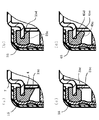
- FIG. 3 (a) to 3 (d) are partial cross-sectional views showing the structure of a gasket according to another embodiment of the present invention.
- the gasket 15 shown in FIG. 3 (a) has a configuration in which the thickness of the inner extension portion 15c is increased from the peripheral wall portion inward in the radial direction. Since the area where the inner extending portion 15c supports the separator 4 is increased, the force for supporting the separator 4 is increased, and the reliability is further improved.
- the gasket 25 shown in FIG. 3B has a configuration in which a first notch 25d is provided on the sealing plate 7 side of the end surface in the radial direction of the inner extension 25c.
- a first notch 25d is provided on the sealing plate 7 side of the end surface in the radial direction of the inner extension 25c.
- the gasket 35 shown in FIG. 3 (c) has a configuration in which a second cutout portion 35e is provided on the end surface of the inner extension portion 35c on the inner side in the radial direction opposite to the sealing plate 7.
- the second cutout portion 35e functions as a guide for bringing the separator 4 and the inner extension portion 35c into close contact with each other.
- the gasket 45 shown in FIG. 3 (d) is configured to have the characteristics of the gaskets 15, 25, and 35 shown in FIGS. 3 (a) to 3 (c). That is, the gasket 45 increases the thickness of the inner extending portion 45c from the peripheral wall portion inward in the radial direction, and is provided with a first cutout portion 45d and a second cutout portion 45e. It has a configuration.
- the gasket 5 was obtained by injection-molding 6,6 nylon into a predetermined shape shown in FIG.
- the length (width) of the end face in the radial direction of the inner extension 5c was 0.8 mm.
- the negative electrode current collector 6 is pressed into a nail mold having a total length of 33.0 mm so that the diameter of the collar portion is 3.2 mm and the diameter of the trunk portion is 1.15 mm using a brass wire. Tin plating was applied to the surface.
- the sealing plate 7 was obtained by pressing a nickel-plated steel plate having a thickness of 0.5 mm into a predetermined shape shown in FIG. The surface of the sealing plate 7 was further subjected to tin plating with a thickness of about 2 ⁇ m.
- the negative electrode current collector 6 was integrated by being electrically welded to the sealing plate 7.
- Electrolytic manganese dioxide powder having an average particle diameter of 35 ⁇ m and graphite powder having an average particle diameter of 9 ⁇ m were mixed at a mass ratio of 93: 7. And this mixture, the aqueous solution containing 39 mass% potassium hydroxide and 2 mass% zinc oxide as an alkaline electrolyte, and a titanium oxyhydroxide powder are made into a mass ratio of 100: 1.5: 0.2. Were mixed and mixed well, and then compression molded into flakes. Next, the flaky positive electrode was pulverized into granules, which were classified with a sieve, and those having a particle size of 10 to 100 mesh were pressure-formed into a hollow cylinder to obtain a pellet-shaped positive electrode 2.
- the gelling agent is a combination of polyacrylic acid powder as a thickener and cross-linked branched sodium polyacrylate powder as a water-absorbing polymer.
- the alloy powder was mixed at a mass ratio of 0.24: 0.47: 33.66: 65.63 to obtain a negative electrode 3.
- the zinc alloy powder used contained 0.05% by mass indium, 0.005% by mass bismuth, and 0.006% by mass aluminum, and had a volume average particle diameter of 120 ⁇ m.
- the gasket 5 was disposed at the open end of the battery case 1 and the separator 4 was brought into close contact with the end surface of the inner extension 5c in the radial direction. Thereafter, a sealing plate 7 was installed and sealed by caulking the opening of the battery case 1 in an arc inward, and then the outer surface of the battery case 1 was covered with an exterior label 8 to obtain the battery 1.
- an AA alkaline battery 2 having a sealing structure described in Patent Document 1 (FIG. 4A) was prepared. That is, the opening of the battery case is sealed with a sealing plate via a ring-shaped gasket having an L-shaped cross section, and the separator is brought into contact with the sealing plate through the ring of the gasket. 2 was produced. Other configurations are the same as those of the battery 1.
- 10 sets of battery packs were prepared by arranging two batteries in series and fixing the sides of the batteries with tape. And each assembled battery was dropped on the plastic tile five times continuously from a height of 1.5 m so that the negative electrode terminal faces downward. The dropped assembled battery was observed by thermography, and the surface temperature of the battery was measured. And the number of the assembled batteries in which the negative electrode and the positive electrode caused an internal short circuit due to an impact caused by dropping and generated heat reaching 40 ° C. or higher was counted.
- the alkaline battery of the present invention is suitably used for all devices that use a dry battery as a power source.
Landscapes
- Chemical & Material Sciences (AREA)
- Chemical Kinetics & Catalysis (AREA)
- Electrochemistry (AREA)
- General Chemical & Material Sciences (AREA)
- Engineering & Computer Science (AREA)
- Manufacturing & Machinery (AREA)
- Sealing Battery Cases Or Jackets (AREA)
- Primary Cells (AREA)
Abstract
L'invention concerne une cellule alcaline. Selon l'invention, une électrode positive (2) de forme cylindrique creuse, une électrode négative (3) enveloppée dans la section creuse de l'électrode positive et un séparateur (4) disposé entre l'électrode positive et l'électrode négative sont logés dans un boîtier de cellule cylindrique à fond (1) conjointement avec un électrolyte liquide, et l'ouverture du boîtier de cellule est scellée par une plaque de scellement (7) avec un joint en forme de bague (5) entre eux. Le joint (5) présente une portion de paroi périphérique (5a) intercalée entre le boîtier de cellule et la portion de bordure périphérique de la plaque de scellement, une portion de prolongation extérieure (5b) qui s'étend vers l'intérieur dans la direction diamétrale depuis la portion de paroi périphérique et le long de la plaque de scellement sur le côté de celle-ci en direction de l'ouverture du boîtier de cellule, et une portion de prolongation intérieure (5c) qui s'étend vers l'intérieur dans la direction diamétrale depuis la portion de paroi périphérique et le long de la plaque de scellement sur le côté de celle-ci à l'opposé de l'ouverture du boîtier de cellule. La portion d'extrémité du séparateur (4) est en contact étroit avec la face d'extrémité de la portion de prolongation intérieure (5c) dans la direction diamétrale vers l'intérieur.
Applications Claiming Priority (2)
| Application Number | Priority Date | Filing Date | Title |
|---|---|---|---|
| JP2011127895A JP2014157654A (ja) | 2011-06-08 | 2011-06-08 | アルカリ電池 |
| JP2011-127895 | 2011-06-08 |
Publications (1)
| Publication Number | Publication Date |
|---|---|
| WO2012169122A1 true WO2012169122A1 (fr) | 2012-12-13 |
Family
ID=47295715
Family Applications (1)
| Application Number | Title | Priority Date | Filing Date |
|---|---|---|---|
| PCT/JP2012/003232 Ceased WO2012169122A1 (fr) | 2011-06-08 | 2012-05-17 | Cellule alcaline |
Country Status (2)
| Country | Link |
|---|---|
| JP (1) | JP2014157654A (fr) |
| WO (1) | WO2012169122A1 (fr) |
Cited By (3)
| Publication number | Priority date | Publication date | Assignee | Title |
|---|---|---|---|---|
| CN113261137A (zh) * | 2018-12-28 | 2021-08-13 | 三洋电机株式会社 | 垫片、以及圆筒形电池 |
| CN114639863A (zh) * | 2022-03-28 | 2022-06-17 | 远景动力技术(江苏)有限公司 | 圆柱电池及其制造方法 |
| CN115275456A (zh) * | 2022-08-24 | 2022-11-01 | 广州小鹏汽车科技有限公司 | 电池以及电池的封装方法 |
Citations (7)
| Publication number | Priority date | Publication date | Assignee | Title |
|---|---|---|---|---|
| JPS59123962U (ja) * | 1983-02-07 | 1984-08-21 | 三洋電機株式会社 | 円筒型電池 |
| JPS6048669U (ja) * | 1983-09-09 | 1985-04-05 | 三洋電機株式会社 | 円筒型電池 |
| JPS60193661U (ja) * | 1984-05-31 | 1985-12-23 | 日立マクセル株式会社 | 乾電池 |
| JP2003197163A (ja) * | 2001-12-26 | 2003-07-11 | Fdk Corp | 筒形電池 |
| JP2003536234A (ja) * | 2000-06-21 | 2003-12-02 | エヴァレディー バッテリー カンパニー インコーポレイテッド | 被覆組立体を有するバッテリー構造及びその組立方法 |
| JP2008103222A (ja) * | 2006-10-19 | 2008-05-01 | Fdk Energy Co Ltd | アルカリ乾電池 |
| JP2009158457A (ja) * | 2007-12-07 | 2009-07-16 | Panasonic Corp | アルカリ電池及び電池パック |
-
2011
- 2011-06-08 JP JP2011127895A patent/JP2014157654A/ja not_active Withdrawn
-
2012
- 2012-05-17 WO PCT/JP2012/003232 patent/WO2012169122A1/fr not_active Ceased
Patent Citations (7)
| Publication number | Priority date | Publication date | Assignee | Title |
|---|---|---|---|---|
| JPS59123962U (ja) * | 1983-02-07 | 1984-08-21 | 三洋電機株式会社 | 円筒型電池 |
| JPS6048669U (ja) * | 1983-09-09 | 1985-04-05 | 三洋電機株式会社 | 円筒型電池 |
| JPS60193661U (ja) * | 1984-05-31 | 1985-12-23 | 日立マクセル株式会社 | 乾電池 |
| JP2003536234A (ja) * | 2000-06-21 | 2003-12-02 | エヴァレディー バッテリー カンパニー インコーポレイテッド | 被覆組立体を有するバッテリー構造及びその組立方法 |
| JP2003197163A (ja) * | 2001-12-26 | 2003-07-11 | Fdk Corp | 筒形電池 |
| JP2008103222A (ja) * | 2006-10-19 | 2008-05-01 | Fdk Energy Co Ltd | アルカリ乾電池 |
| JP2009158457A (ja) * | 2007-12-07 | 2009-07-16 | Panasonic Corp | アルカリ電池及び電池パック |
Cited By (5)
| Publication number | Priority date | Publication date | Assignee | Title |
|---|---|---|---|---|
| CN113261137A (zh) * | 2018-12-28 | 2021-08-13 | 三洋电机株式会社 | 垫片、以及圆筒形电池 |
| EP3905403A4 (fr) * | 2018-12-28 | 2022-03-16 | SANYO Electric Co., Ltd. | Joint d'étanchéité et batterie cylindrique |
| CN114639863A (zh) * | 2022-03-28 | 2022-06-17 | 远景动力技术(江苏)有限公司 | 圆柱电池及其制造方法 |
| CN114639863B (zh) * | 2022-03-28 | 2023-07-28 | 远景动力技术(江苏)有限公司 | 圆柱电池及其制造方法 |
| CN115275456A (zh) * | 2022-08-24 | 2022-11-01 | 广州小鹏汽车科技有限公司 | 电池以及电池的封装方法 |
Also Published As
| Publication number | Publication date |
|---|---|
| JP2014157654A (ja) | 2014-08-28 |
Similar Documents
| Publication | Publication Date | Title |
|---|---|---|
| JP5599384B2 (ja) | 陰性缶を有する円筒形ニッケル─亜鉛セル | |
| US7572544B2 (en) | Sealed rechargeable battery | |
| CN110301062B (zh) | 非水电解质二次电池 | |
| US20120171535A1 (en) | Nickel-zinc battery and manufacturing method thereof | |
| JP7686570B2 (ja) | 円筒形電池 | |
| JP7709293B2 (ja) | 円筒形電池 | |
| KR101696964B1 (ko) | 코팅층이 형성된 원통형 이차전지 | |
| CN109075305A (zh) | 非水电解质二次电池 | |
| JP2006351512A (ja) | 密閉型二次電池およびその製造方法 | |
| CN107068942A (zh) | 圆筒形锂离子电池 | |
| US9601735B2 (en) | Cylindrical battery | |
| EP4131559A1 (fr) | Batterie de stockage alcaline | |
| WO2012169122A1 (fr) | Cellule alcaline | |
| JP2008204839A (ja) | 円筒形電池用封口板 | |
| JP2013093294A (ja) | 密閉型電池 | |
| JP5110889B2 (ja) | ニッケル水素二次電池 | |
| JP4079563B2 (ja) | 蓄電池およびその製造方法 | |
| JP4931492B2 (ja) | 円筒型蓄電池 | |
| JP2015125869A (ja) | アルカリ二次電池 | |
| CN113454828B (zh) | 碱性充电电池 | |
| JP5981807B2 (ja) | アルカリ電池 | |
| KR100995766B1 (ko) | 안전성이 향상된 원통형 이차전지 | |
| JP2014044855A (ja) | アルカリ電池 | |
| JP2011008930A (ja) | 円筒型アルカリ蓄電池 | |
| JP2014179267A (ja) | 円筒形電池の蓋構造体、円筒形電池 |
Legal Events
| Date | Code | Title | Description |
|---|---|---|---|
| 121 | Ep: the epo has been informed by wipo that ep was designated in this application |
Ref document number: 12797177 Country of ref document: EP Kind code of ref document: A1 |
|
| NENP | Non-entry into the national phase |
Ref country code: DE |
|
| 122 | Ep: pct application non-entry in european phase |
Ref document number: 12797177 Country of ref document: EP Kind code of ref document: A1 |
|
| NENP | Non-entry into the national phase |
Ref country code: JP |