WO2012169165A1 - Système d'éclairage - Google Patents
Système d'éclairage Download PDFInfo
- Publication number
- WO2012169165A1 WO2012169165A1 PCT/JP2012/003634 JP2012003634W WO2012169165A1 WO 2012169165 A1 WO2012169165 A1 WO 2012169165A1 JP 2012003634 W JP2012003634 W JP 2012003634W WO 2012169165 A1 WO2012169165 A1 WO 2012169165A1
- Authority
- WO
- WIPO (PCT)
- Prior art keywords
- unit
- holding frame
- control unit
- illumination system
- conductive member
- Prior art date
- Legal status (The legal status is an assumption and is not a legal conclusion. Google has not performed a legal analysis and makes no representation as to the accuracy of the status listed.)
- Ceased
Links
Images



















Classifications
-
- F—MECHANICAL ENGINEERING; LIGHTING; HEATING; WEAPONS; BLASTING
- F21—LIGHTING
- F21V—FUNCTIONAL FEATURES OR DETAILS OF LIGHTING DEVICES OR SYSTEMS THEREOF; STRUCTURAL COMBINATIONS OF LIGHTING DEVICES WITH OTHER ARTICLES, NOT OTHERWISE PROVIDED FOR
- F21V21/00—Supporting, suspending, or attaching arrangements for lighting devices; Hand grips
- F21V21/34—Supporting elements displaceable along a guiding element
- F21V21/35—Supporting elements displaceable along a guiding element with direct electrical contact between the supporting element and electric conductors running along the guiding element
-
- F—MECHANICAL ENGINEERING; LIGHTING; HEATING; WEAPONS; BLASTING
- F21—LIGHTING
- F21V—FUNCTIONAL FEATURES OR DETAILS OF LIGHTING DEVICES OR SYSTEMS THEREOF; STRUCTURAL COMBINATIONS OF LIGHTING DEVICES WITH OTHER ARTICLES, NOT OTHERWISE PROVIDED FOR
- F21V23/00—Arrangement of electric circuit elements in or on lighting devices
- F21V23/06—Arrangement of electric circuit elements in or on lighting devices the elements being coupling devices, e.g. connectors
-
- H—ELECTRICITY
- H05—ELECTRIC TECHNIQUES NOT OTHERWISE PROVIDED FOR
- H05B—ELECTRIC HEATING; ELECTRIC LIGHT SOURCES NOT OTHERWISE PROVIDED FOR; CIRCUIT ARRANGEMENTS FOR ELECTRIC LIGHT SOURCES, IN GENERAL
- H05B44/00—Circuit arrangements for operating electroluminescent light sources
-
- F—MECHANICAL ENGINEERING; LIGHTING; HEATING; WEAPONS; BLASTING
- F21—LIGHTING
- F21Y—INDEXING SCHEME ASSOCIATED WITH SUBCLASSES F21K, F21L, F21S and F21V, RELATING TO THE FORM OR THE KIND OF THE LIGHT SOURCES OR OF THE COLOUR OF THE LIGHT EMITTED
- F21Y2105/00—Planar light sources
-
- F—MECHANICAL ENGINEERING; LIGHTING; HEATING; WEAPONS; BLASTING
- F21—LIGHTING
- F21Y—INDEXING SCHEME ASSOCIATED WITH SUBCLASSES F21K, F21L, F21S and F21V, RELATING TO THE FORM OR THE KIND OF THE LIGHT SOURCES OR OF THE COLOUR OF THE LIGHT EMITTED
- F21Y2115/00—Light-generating elements of semiconductor light sources
- F21Y2115/10—Light-emitting diodes [LED]
- F21Y2115/15—Organic light-emitting diodes [OLED]
-
- Y—GENERAL TAGGING OF NEW TECHNOLOGICAL DEVELOPMENTS; GENERAL TAGGING OF CROSS-SECTIONAL TECHNOLOGIES SPANNING OVER SEVERAL SECTIONS OF THE IPC; TECHNICAL SUBJECTS COVERED BY FORMER USPC CROSS-REFERENCE ART COLLECTIONS [XRACs] AND DIGESTS
- Y02—TECHNOLOGIES OR APPLICATIONS FOR MITIGATION OR ADAPTATION AGAINST CLIMATE CHANGE
- Y02B—CLIMATE CHANGE MITIGATION TECHNOLOGIES RELATED TO BUILDINGS, e.g. HOUSING, HOUSE APPLIANCES OR RELATED END-USER APPLICATIONS
- Y02B20/00—Energy efficient lighting technologies, e.g. halogen lamps or gas discharge lamps
- Y02B20/30—Semiconductor lamps, e.g. solid state lamps [SSL] light emitting diodes [LED] or organic LED [OLED]
Definitions
- the present invention relates to an illumination system using an EL element as a light source.
- the electroluminescence (EL) element has a light emitting part formed on a transparent substrate, which is configured by arranging a light emitting layer between a positive electrode and a negative electrode. When a voltage is applied between the electrodes, the EL element emits light by excitons generated by recombination of electrons and holes injected as carriers in the light emitting layer.
- the EL element is roughly classified into an organic EL element having a light emitting layer formed of an organic compound and an inorganic EL element formed of an inorganic compound.
- an organic EL element can emit light with high luminance at a low voltage, and various emission colors can be obtained depending on the type of organic compound, and since it can be easily manufactured as a flat light-emitting panel, Attention has been focused on use as a light source for lighting equipment.
- a light emitting panel using an EL element and a circuit board for controlling the lighting of the light emitting panel are incorporated into a case and modularized (for example, , See Patent Document 1).
- the present invention has been made in view of the above problems, and an object of the present invention is to provide an illumination system that can reduce the wiring space in the living space and that allows easy construction and replacement of the light source.
- the present invention includes an EL unit having a light emitting unit, a holding frame that holds the EL unit, and a control unit that controls lighting of the EL unit, and the holding frame has a rail shape. And a power signal and a communication signal are transmitted between the control unit and the EL unit through the conductive member.
- the EL unit has a control unit that receives a communication signal from the control unit and controls a light emitting state of the light emitting unit.
- control unit includes a power supply unit that transmits power to the conductive member.
- the lighting system includes a pair of protection units disposed at both ends of the holding frame to protect the conductive member, and the control unit is built in one of the protection units.
- the lighting system includes a case unit held by the holding frame, and the control unit is built in the case unit.
- the holding frame includes a movable cover member that covers the conductive member, and the conductive member is exposed to the EL unit by moving the cover member.
- the holding frame is elongated, and includes a pair of concave stripes formed between both longitudinal ends thereof, and the EL unit has the concave portion on a surface facing the holding frame. It is preferable that a pair of convex portions that engage with the strip is provided, and that the convex portion is held by the holding frame by engaging the concave strip.
- the holding frame is elongated, and includes a hook portion formed on one edge portion along a longitudinal direction thereof, and a concave portion formed on the other edge portion, and the hook portion is
- the EL unit is slidable in a state of being biased in a direction perpendicular to the longitudinal direction, and the EL unit is engaged with the hooked portion that engages with the hook portion on the surface facing the holding frame, and the concave portion. It is preferable that the projection is held by the holding frame by locking the projection to the recess and locking the hook portion to the hook portion.
- the holding frame is elongated, and includes a pair of recesses formed on both edge portions along the longitudinal direction thereof, and the EL unit has the recesses on a surface facing the holding frame.
- a pair of convex portions to be locked is provided, and one of the pair of convex portions is slidable in a state of being biased in a direction orthogonal to the longitudinal direction of the holding frame, and the one convex portion is formed into the concave portion. It is preferable that the holding frame is held by locking the other convex portion with the concave portion.
- the EL unit includes a fixing portion protruding toward the holding frame on a surface facing the holding frame, and the fixing portion is biased in a direction orthogonal to the protruding direction.
- a pair of slidable claw portions the holding frame has a receiving portion to which the claw portion is locked at a position facing the fixed portion, and the EL unit includes the pair of claw portions It is preferable to be held by the holding frame by engaging with the receiving portion.
- the EL unit includes a fixed portion protruding toward the holding frame on a surface facing the holding frame, and the fixed portion is biased in a direction orthogonal to the protruding direction.
- the holding frame has a long shape, and has a receiving strip on which the claw portion is locked across both longitudinal ends thereof. It is preferable that the pair of claws are held by the holding frame by locking the pair of claws to the receiving strip.
- the EL unit and the holding frame are connected by a wire.
- control unit and the EL unit perform mutual authentication, and the control unit supplies power to the EL unit when the EL unit is authenticated.
- control unit outputs a warning signal when the EL unit is removed from the holding frame.
- control unit does not output the warning signal when management information is input by an administrator.
- the connection between the control unit and the EL unit is made by the conductive member provided in the holding frame that holds the EL unit, the space for wiring in the living space can be reduced.
- the EL unit and the control unit are connected to the holding frame constructed on the construction surface, the connection is made, so no special skill is required, and the resident installs the lighting system appropriately.
- the EL unit can be easily replaced.
- FIG. 1 is a perspective view of an illumination system according to a first embodiment of the present invention.
- (A) is a schematic diagram which shows the wiring path
- (b) is a schematic diagram which shows the wiring path
- (A) (b) is the side view seen from the edge part side of the modification.
- (A) (b) is the side view seen from the edge part side of the illumination system.
- the perspective view of the holding frame used for the illumination system which concerns on the 3rd Embodiment of this invention.
- the perspective view of EL unit used for the illumination system. (A) (b) is the side view seen from the edge part side of the illumination system.
- the top view of the holding frame used for the modification. (A) (b) is the side view seen from the edge part side of the modification.
- the perspective view of EL unit used for the lighting system which concerns on the 4th Embodiment of this invention.
- the perspective view of the holding frame used for the illumination system (A) (b) is the side view seen from the edge part side of the illumination system.
- (A) and (b) are the elements on larger scale of the holding frame.
- the perspective view of EL unit used for the illumination system which concerns on the 5th Embodiment of this invention.
- (A) (b) is the side view seen from the edge part side of the illumination system.
- movement flow of the illumination system which concerns on the 7th Embodiment of this invention.
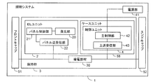
- the illumination system 1 of the present embodiment controls lighting of the EL unit 2 having a light emitting unit 20 using an organic EL element, a holding frame 3 that holds the EL unit 2, and the EL unit 2. And a control unit 4.
- the holding frame 3 includes a rail-shaped conductive member 30.
- the conductive member 30 transmits power and a communication signal between the control unit 4 and the EL unit 2.
- a pair of protection units 5 that protect the ends of the conductive member 30 are disposed at both ends of the holding frame 3.
- the protection unit 5 includes a front cap 51 attached to one side end of the holding frame 3 and an end cap 52 attached to the other side end.
- the illumination system 1 of the present embodiment provides a plurality of EL units 2 for one holding frame 3.
- a predetermined address is set for each EL unit 2.
- the control unit 4 can control lighting of the plurality of EL units 2 individually.
- the holding frame 3 is about twice as long as the EL unit 2, but actually a longer frame is used, and a plurality of holding frames 3 are connected and used. May be.
- the control unit 4 includes a power supply unit 41 that converts commercial power into a predetermined direct current, a main control unit 42 that controls power to the light emitting unit 20 and communication information, and a main control unit 42. And a main transmission / reception unit 43 that transmits power and communication information to the conductive member 30 under control.
- the control unit 4 is built in the front cap 51 (one of the protection units 5). When the front cap 51 is disposed at the end of the holding frame 3, the main transmission / reception unit 43 comes into contact with the conductive member 30, and these are electrically connected.
- the power supply unit 41 includes an AC / DC converter including a switching power supply, a transformer, and the like, and generates a current transmitted to the conductive member 30.
- the power supply unit 41 may be separately provided with a secondary battery that converts an alternating current supplied from a commercial power source into a direct current and stores it, and is not connected to the commercial power source and is appropriately replaced.
- a general-purpose battery may be used.
- the main control unit 42 is configured by a general-purpose CPU, a memory control, and a storage device. The main control unit 42 recognizes the EL unit 2 held in the holding frame 3 and controls the main transmission / reception unit 43 so as to supply predetermined power to the EL unit 2.
- the main transmission / reception unit 43 includes a voltage control circuit, an inverter circuit, and the like, and transmits the direct current superimposed with the communication information to the conductive member 30 as described above under the control of the main control unit 42.
- the control unit 4 also includes an interface unit (not shown) through which an administrator inputs management information such as address information and dimming information of the EL unit 2 used in the system.
- the holding frame 3 is provided with a rail-like conductive member 30 between both ends where the front cap 51 and the end cap 52 are provided.
- the conductive member 30 is a conductive metal plate such as a copper foil plate. Part or all of one surface of the conductive member 30 is exposed toward the EL unit 2, and this exposed portion serves as a power feeding point with the EL unit 2.
- the conductive member 30 is shown as a single plate-like member, but both the positive electrode line and the negative electrode line are insulated from each other.
- the EL unit 2 includes, in addition to the light emitting unit 20, a panel control unit 21 that controls the light emitting state of the light emitting unit 20 and a panel transmission / reception unit 22 that is electrically connected to the conductive member 30.
- the light emitting unit 20 includes a light emitting unit (not shown) in which a positive electrode made of a transparent conductive film, a light emitting layer having a light emitting function, and a negative electrode having light reflectivity are sequentially stacked on a rectangular substrate having a light transmitting property. It is formed and the outside of the light emitting part is covered with a sealing material.
- an organic EL element using an organic light emitting material for the light emitting layer is preferably used.
- the light emitting unit 20 is provided with an electrode extraction terminal 20a (see FIG. 5 described later) corresponding to each of the positive electrode and the negative electrode via an auxiliary electrode or the like on the surface opposite to the light emitting surface.
- the panel control unit 21 includes various elements such as a general-purpose microcomputer, a memory, and a transformer circuit mounted on a wiring board.
- the panel control unit 21 receives power from the conductive member 30 and a communication signal from the control unit 4 and emits light from the light emitting unit 20. The light emission state is directly controlled. Also, information such as the address and configuration of the EL unit 2 (light emitting unit 20) is transmitted to the main control unit 42 of the control unit 4.
- the panel transmitting / receiving unit 22 includes a connection terminal that contacts the conductive member 30, and electrically connects the conductive member 30 and the panel control unit 21.
- the holding frame 3 is a long member, and a pair of ridges 32 are provided at the center of one surface of a fixed surface 31 fixed to a construction surface such as an indoor wall or a building material. Is formed along the longitudinal direction, and the conductive member 30 is disposed on the bottom surface of the concave portion sandwiched between the pair of convex portions 32. As described above, a copper foil plate is used for the conductive member 30, and silver plating or the like for preventing welding is preferably applied to this surface.
- the surface of the fixed surface 31 where the conductive member 30 is not disposed is formed as a smooth surface.
- the edge of the fixed surface 31 protrudes in a bowl shape in the short direction of the holding frame 3 (see also FIG. 7 described later). If it carries out like this, it will become easy to distinguish the front and back of the holding frame 3 at the time of construction, and since the contact area of the fixed surface 31 and a construction surface becomes large, construction stability can be improved.
- Both edge portions 33 of the holding frame 3 are erected vertically from the fixed surface 31 and are formed to be thick so as to be higher than the protruding height of the ridge portion 32 and to have a predetermined width. These two edge portions 33 are formed in a stepped manner so that the outer edge side becomes higher, and the outer edges abut against the back surface edge portion of the EL unit 2.
- recesses 33 a are respectively formed between both longitudinal ends of the holding frame 3.
- the pair of concave stripes 33 a are disposed symmetrically with respect to the conductive member 30 at both edge portions 33 of the holding frame 3.
- screw holes 34 through which screws for fixing the front cap 51 and the end cap 52 are inserted are formed in the side end surfaces of both edge portions 33, respectively.
- a portion (not shown) is formed.
- a plastic material such as an ABS resin, an acrylic resin, or a polystyrene resin, or a metal material such as aluminum whose surface is subjected to insulation treatment is used.
- the front cap 51 and the end cap 52 are formed in shapes in which the end surfaces in contact with the holding frame 3 respectively correspond to both end portions of the holding frame 3. These thicknesses (height from the construction surface) are substantially equal to the thickest portions of both edge portions 33 of the holding frame 3. Further, through holes 53 and 54 are formed at the edges of the front cap 51 and the end cap 52 so as to be continuous with the screw holes 34 of the holding frame 3. Screws (not shown) inserted through the through holes 53 and 54 are screwed into the screw holes 34, whereby the front cap 51 and the end cap 52 are connected to both ends of the holding frame 3, respectively.
- connection methods you may connect them with a spring piece etc., for example, if the front cap 51 and the end cap 52 can be suitably attached or detached to the holding frame 3, it is restricted to the screw fixation mentioned above. Absent.
- the edge portions on the construction surface side of the front cap 51 and the end cap 52 protrude in a bowl shape so as to be continuous with both edge portions of the holding frame 3. In this way, it is possible to easily distinguish the front and back of the front cap 51 and the end cap 52 when connecting to the holding frame 3.
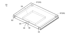
- the front cap 51 of the present embodiment is a case-like member having a predetermined width in the direction in which the holding frame 3 is connected, and has a storage portion 55 for interior of the control unit 4 as shown in FIG. .
- the front cap 51 is provided with a signal input / output contact portion 44 from the inside of the storage portion 55 toward an end portion connected to the holding frame 3.
- the contact portion 44 is in contact with the main transmission / reception portion 43 (see FIG. 2) of the control unit 4 housed in the storage portion 55, and is formed so as to slightly protrude from the end portion of the front cap 51. Comes into contact with the conductive member 30 of the holding frame 3 when connected to the holding frame 3. Thereby, the main transmission / reception unit 43 (see FIG.
- the control unit 4 is electrically connected to the conductive member 30 of the holding frame 3 via the contact point 44.
- the contact portion 44 is also subjected to silver plating for preventing welding.
- Two positioning holes 56 are formed at the end portion of the front cap 51 connected to the holding frame 3 so as to sandwich the contact portion 44.
- a positioning pin (not shown) is provided at the end of the holding frame 3 so as to be continuous with the ridge portion 32. The positioning pin is fitted into the positioning hole 56, and the holding frame 3, the front cap 51, and the like. Is positioned.
- a through hole 53 is formed with a countersink 57 having a large hole diameter at an end opposite to the end connected to the holding frame 3, and a screw head of a screw is accommodated in the counterbore 57. In this way, the screw head is not exposed and the appearance can be improved.
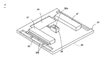
- the EL unit 2 has a case 23 that houses the light emitting unit 20.
- the front surface of the case 23 has translucency and is formed as a surface that guides light from the light emitting unit 20.
- a pair of convex portions 27 that are engaged with the concave stripes 33 a of the holding frame 3 are formed on the rear surface of the case 23.
- Wiring grooves are formed between the guide block 25 and the recess 24 and between the recess 24 and the opening 26, respectively.
- the guide block 25 is formed in a size that fits between the pair of protruding strips 32 of the holding frame 3.
- the power supply terminal 22a is disposed so that its tip slightly protrudes from the guide block 25, and is urged in the protruding direction. Similarly to the contact portion 44 and the conductive member 30, the power supply terminal 22a is subjected to silver plating or the like for preventing welding.
- the same plastic material or metal material as the holding frame 3 is used as a constituent material of the case 23.
- the EL unit 2 has, for example, a 150 mm square shape.
- the standard panel size of the building material is 300 mm square. That is, if it is this size, the lighting system 1 can be comprised in the form melt
- the LEL unit 2 is slid and inserted from the end of the holding frame 3, and the convex portion 27 of the EL unit 2 is inserted into the concave line of the holding frame 3.
- the EL unit 2 is held by the holding frame 3 by being locked to 33a.
- the power supply terminal 22a of the EL unit 2 contacts the conductive member 30 of the holding frame 3, and these are electrically joined.
- the EL unit 2 is slidable along the longitudinal direction of the holding frame 3 by the convex portions 27 and the guide blocks 25 of the EL unit 2 being guided by the concave stripes 33a and the convex stripe portions 32 of the holding frame 3, respectively. Retained.
- the front cap 51 is disposed at one end of the holding frame 3 in a state where the EL unit 2 is held at a predetermined position of the holding frame 3.
- the EL unit 2 is electrically connected by the conductive member 30. Further, by providing the end cap 52 at the other end of the holding frame 3, the end of the conductive member 30 is protected. Thereby, construction of lighting system 1 is made.
- EL unit 2 can be arrange
- either the front cap 51 or the end cap 52 may be removed, and the EL unit 2 may be slid along the holding frame 3 and removed from the end of the holding frame 3.
- the holding frame 3 and the EL unit 2 are formed to have a thickness of 12 mm or less when the EL unit 2 is held by the holding frame 3. Therefore, if the thickness of the holding frame 3 and the EL unit 2 is set to 12 mm or less, the EL unit 2 does not protrude when they are incorporated into the building material, and the feeling of space expansion can be improved. In contrast, the building material (wall) itself can be given a visual effect.
- a case unit 58 formed in substantially the same shape as the EL unit 2 may be held at a location where the EL unit 2 is not held in the holding frame 3.
- the case unit 58 is a so-called dummy case that hides the conductive member 30 and the like of the holding frame 3. By providing this, the appearance of the lighting system 1 can be improved.
- the case unit 58 may be equipped with devices other than the EL unit 2 such as a human sensor. Similar to the EL unit 2, this type of device is also connected to the control unit 4 via the conductive member 30 of the holding frame 3 and incorporated in the lighting system 1.
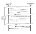
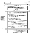
- the lighting system 1 periodically performs (1) a monitoring (detection) phase, (2) an authentication / configuration phase, and (3) a power feeding phase between the control unit 4 and the EL unit 2.
- (1) monitoring (detection) phase is a phase in which the control unit 4 monitors the connection state of the EL unit 2 connected to the conductive member 30 and detects the connection.
- the control unit 4 outputs a detection signal through the conductive member 30.
- This detection signal includes information such as frequency modulation, power capacity, and current change in the communication signal transmitted from the control unit 4.
- the EL unit 2 When the EL unit 2 receives the detection signal through the conductive member 30, the EL unit 2 outputs a confirmation signal to the control unit 4.
- the control unit 4 receives this confirmation signal, the lighting system 1 proceeds to (2) the authentication / configuration phase.
- the transmission / reception of these signals is performed by the main transmission / reception unit 43 under the control of the main control unit 42 in the control unit 4, and the panel transmission / reception unit under the control of the panel control unit 21 in the EL unit 2.
- the authentication / configuration phase is a phase in which the control unit 4 confirms the address of the EL unit 2 whose connection state is confirmed in the above (1) monitoring (detection) phase and its configuration. Also in this phase, first, a confirmation signal is output from the control unit 4 to the EL unit 2 via the conductive member 30. Upon receiving this confirmation signal, the EL unit 2 outputs address information assigned to itself and information such as the rated current of the light emitting unit 20 incorporated in the EL unit 2 to the control unit 4. These pieces of information (packets) are written in the memory (main control unit 42) of the control unit 4. Upon receiving these pieces of information, the control unit 4 authenticates that the EL unit 2 is suitable for the lighting system 1.
- the illumination system 1 transfers to (3) electric power feeding phase.
- the above-described information transmission / reception is not performed.
- the authentication of the EL unit 2 is not performed, and the control unit 4 determines that power cannot be supplied to the conductive member 30 as shown in FIG.
- the power feeding phase is a mode in which a predetermined direct current is actually supplied from the control unit 4 and the EL unit 2 is turned on.
- information on the operation (lighting) time of the light emitting unit 20 incorporated in the EL unit 2 is provided from the EL unit 2 to the control unit 4.
- the control unit 4 determines whether or not the operation time of the light emitting unit 20 exceeds the rated drive time (lifetime), and if so, a notification recommending replacement of the EL unit 2 To do. This notification is performed, for example, by blinking the EL unit 2 to be replaced at a predetermined cycle.
- the light emission lifetime of an organic EL element depends on the deterioration over time of the organic material used for the light emitting layer, and the light emission luminance gradually decreases. Therefore, it may be difficult for the resident (manager) to notice. Therefore, in the lighting system 1, the EL unit 2 that has exceeded the lifetime is blinked as if the conventional fluorescent lamp has run out, thereby notifying the resident of the replacement time of the EL unit 2.
- the notification is canceled.
- the notification is performed again at a predetermined cycle. Even when the EL unit 2 is not removed, the administrator can appropriately cancel the notification by operating the interface unit provided in the control unit 4, and the notification cycle can be changed. It can be set arbitrarily.
- a power supply unit ( ⁇ ) that supplies power to an illumination load ( ⁇ ) such as an EL unit and a communication signal such as control information of the illumination load.
- a control unit ( ⁇ ) for transmitting and receiving is individually provided, and they are connected to each lighting load through different paths.
- a space for wiring both the power line and the information line is required inside the wall or ceiling, and there are cases where the living space is restricted in order to secure the space.
- wiring becomes complicated, special skills and man-hours are required for construction.
- the control unit 4 and the EL unit 2 are electrically connected by the conductive member 30 provided on the holding frame 3 that holds the EL unit 2.
- FIGS. 1 and 2 transmits power and communication information between them (see FIGS. 1 and 2). That is, as shown in FIG. 13B, a power supply unit ( ⁇ ) that supplies power to an illumination load ( ⁇ ) such as an EL unit, and a control unit that transmits and receives communication signals such as control information of the illumination load ( ⁇ ) is integrated. Moreover, they are connected to each lighting load by the same route. In addition, since this wiring is formed by the conductive member 30 provided on the holding frame 3 that holds the EL unit 2, a space for wiring as in the conventional case becomes unnecessary, and a living space with a sense of openness is realized. Can do. In addition, since the holding frame 3 is fixed to the construction surface, and the EL unit 2 and the control unit 4 are simply connected to the holding frame 3, wiring is performed. The lighting system 1 can be constructed, and the EL unit 2 can be easily replaced.
- the conventional power supply line merely applies a constant voltage to the lighting load, and the information line only gives a simple command to the ON / OFF of the electricity, dimming, and the like. Therefore, in a lighting system having high functionality that can realize a lighting effect of a space using a plurality of lighting loads, individual specific settings for each lighting load need to be performed at the time of construction. This setting requires a certain amount of know-how and skills for construction, and it was not easy to adopt this kind of lighting system in general houses and offices.
- the power supply line and the information line are integrated into a signal from one control unit 4, and the detailed dimming control of each EL unit 2 is performed on the EL unit 2 on the terminal side. This is done by the panel control unit 21 (see FIG. 2) provided in FIG. Therefore, it is not necessary to make a special setting for each EL unit 2, and even an end user who has no know-how can easily install and replace the EL unit 2.
- the conductive member 30 is formed in the central portion of the holding frame 3 along the longitudinal direction thereof. According to this configuration, since the distance between the electrode lines is shorter than the configuration in which the conductive member 30 (positive electrode line and negative electrode line) is formed on both edge portions 33 of the holding frame 3, noise is generated. Can be difficult. Further, even when a plurality of holding frames 3 are provided on the construction surface at regular intervals, the distance from the conductive member 30 provided on the adjacent holding frame 3 is not close, and a certain interval is ensured. Can do. Therefore, when transmitting power and communication information, the control unit 4 can stably control the lighting of the EL unit 2 without being affected by noise of the other conductive members 30.
- the illumination system 1 according to this modification is provided with a case unit 58 at a location where the EL unit 2 of the holding frame 3 is not held, similarly to the configuration shown in FIG.
- the control unit 4 is built in the case unit 58.
- the front cap 51 is disposed at the end of the holding frame 3 to insulate and protect the end of the conductive member 30, and the same one as the end cap 52 described above is used.
- a power supply unit 41 is provided outside the control unit 4.
- Other configurations are the same as in the above embodiment.
- the control unit 4 since the control unit 4 is built in the case unit 58 held by the holding frame 3, the front cap 51 of the size shown in the above embodiment is arranged in the direction of the end of the holding frame 3 on the construction surface. It is preferably used when there is no space to install. Further, in this modification, the power supply unit 41 is provided at a position away from the holding frame 3 and the EL unit 2, so that it is difficult to be affected by heat from the power supply unit 41 in the holding frame 3 and the EL unit 2. be able to.
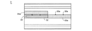
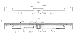
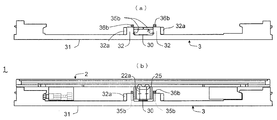
- the holding frame 3 includes a conductive cover 30 and a movable cover member 35 a.
- a hinge mechanism 36a is provided on one of the pair of ridges 32, and the cover member covers the upper surface of the pair of ridges 32 as well as the conductive member 30 via the hinge mechanism 36a.
- 35a is provided.
- the hinge mechanism 36a makes the cover member 35a rotatable in a direction orthogonal to the longitudinal direction of the holding frame 3, and is fixed at a position covering the conductive member 30 by a built-in spring member (not shown). It is energized.
- the conductive member 30 is exposed to the EL unit 2 by rotating the cover member 35a against the biasing direction.
- the cover member 35 a exists at a position covering the conductive member 30 as shown in FIG. Then, the EL unit 2 is inserted into the holding frame as shown in FIG. 18B by slidingly inserting the EL unit 2 from the end of the holding frame 3 while the cover member 35a is rotated by the operator. 3 and the power supply terminal 22a of the EL unit 2 and the conductive member 30 are electrically connected.
- a slide mechanism that moves the cover member 35a horizontally may be provided.
- the conductive member 30 is covered with the cover member 35a at the portion of the holding frame 3 where the EL unit 2 is not held, so that the conductive member 30 is protected from dust and the like. can do.
- a dummy case unit 58 as shown in FIG. 8 may be provided at a portion of the holding frame 3 where the EL unit 2 is not held, and it can be used together with the cover member 35a of this modification. The conductive member 30 can be more reliably protected from dust and the like.
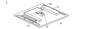
- the holding frame 3 has a long shape, the hook portion 38 formed on one edge portion 33b along the longitudinal direction, and the other edge portion 33c. And a recess 33d formed on the surface.
- a part of the hook portion 38 is embedded in the edge portion 33 b and is configured to be slidable in a state of being biased in a direction orthogonal to the longitudinal direction of the holding frame 3.
- the hook portion 38 includes a flange portion 38a exposed inside the edge portion 33b, a biasing spring 38b that biases the flange portion 38a toward the edge portion 33b of the holding frame 3, and an outer side of the edge portion 33b. And an exposed push button 38c.
- the conductive member 30 is embedded in the fixed surface 31, and only the portion corresponding to the mounting location of the EL unit 2 is exposed. Further, the protruding strip portion 32 of the holding frame 3 is not partially formed in a portion close to the exposed portion of the conductive member 30.
- the illumination system 1 of the present embodiment is configured so that the EL unit 2 is engaged with the hook portion 38 on the surface facing the holding frame 3 corresponding to the holding frame 3.
- a portion 27a is provided.
- Other configurations are the same as those in the first embodiment.
- the hooked portion 27a of the EL unit 2 and the hook The flange portion 38a of the portion 38 is coupled.
- the EL unit 2 is held by the holding frame 3. Since the protrusion 32 of the holding frame 3 is not formed in a portion adjacent to the guide block 25 of the EL unit 2 (see FIG. 19), the guide block 25 contacts the protrusion 32 when the EL unit 2 is attached.
- the convex portion 27 of the EL unit 2 can be smoothly pushed into the concave portion 33d of the holding frame 3 without contacting.
- An elastic member (not shown) for preventing rattling may be disposed in the recess 33d.
- the push button 38 c is pushed in similarly to the above attachment procedure, and the connection between the hook portion 38 a of the hook portion 38 and the hooked portion 27 a is released. In this state, the EL unit 2 can be easily detached from the holding frame 3 by lifting the end of the EL unit 2 where the hooked portion 27a is provided.
- the EL unit 2 can be easily detached from the holding frame 3 without removing the front cap 51 or the end cap 52 (see FIG. 1) from the holding frame 3.
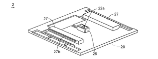
- the holding frame 3 has a long shape, and includes a pair of concave portions 33 e formed on both edge portions 33 along the longitudinal direction thereof.
- a pressing jig 33f is embedded in each of the recesses 33e.
- the push jig 33f is formed so as to be slidable only inward from the edge 33 of the holding frame 3.
- the EL unit 2 includes a pair of convex portions 27 that are engaged with the concave portions 33e of the holding frame 3 on the surface facing the holding frame, and one of the pair of convex portions 27 is the length of the holding frame 3. It is configured to be slidable while being urged in a direction orthogonal to the direction.
- the one protrusion 27 is provided with a protrusion 27b that protrudes toward the recess 33e of the holding frame 3, and the protrusion 27b is a spring in the protrusion direction. Slide in the energized state.
- Other configurations are the same as those of the second embodiment.
- This repulsive force acts in a direction in which the space between the concave portions 33e of the holding frame facing the convex portions 27 of the EL unit 2 is expanded.
- the EL unit 2 is held by the holding frame 3.
- the engagement between the convex portion 27 (projecting portion 27b) and the concave portion 33e of the EL unit 2 is released by pushing the pushing jig 33f.
- the EL unit 2 can be easily detached from the holding frame 3 by lifting the end portion provided with the convex portion 27 (protruding portion 27b) facing the pushed pushing jig 33f.
- the EL unit 2 can be easily detached from the holding frame 3 without removing the front cap 51 or the end cap 52 (see FIG. 1) from the holding frame 3. Can do.
- a lighting system according to a modification of the present embodiment will be described with reference to FIGS.
- the conductive member 30 is covered with a double-spread type cover member 35b.
- a pair of support ridges 32a are provided in both edge directions of the exposed portion of the conductive member 30 so as to be slightly wider than the interval between the pair of ridge portions 32, and these support ridges 32a.
- a pair of cover members 35b is rotatably supported by a hinge mechanism 36b provided on the upper surface of each.
- the hinge mechanism 36b is configured to bias the spring so that the cover member 35b is in a closed state.
- Other configurations are the same as those of the third embodiment.
- the cover member 35b covers the conductive member 30 by the spring bias of the hinge mechanism 36b. It becomes a state.
- the cover member 35b is pushed in by the guide block 25 of the EL unit 2, and the cover member 35b Arranged parallel to the side.
- the conductive member 30 is covered with the cover member 35b at the portion of the holding frame 3 where the EL unit 2 is not held. Can be protected from etc.
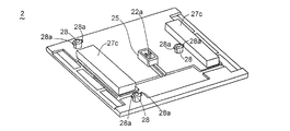
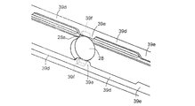
- the EL unit 2 includes a fixing portion 28 that protrudes toward the holding frame 3 on the surface facing the holding frame 3.
- the fixing portion 28 has a pair of claw portions 28a that can slide while being urged in a direction orthogonal to the protruding direction.
- the fixed portion 28 is formed in a columnar shape, and is disposed on the outer surface on the distal end side of the fixed portion 28 so that the pair of claw portions 28a protrude symmetrically, and the pair of claw portions 28a are in directions opposite to each other. Is being energized.
- claw part 28a is formed so that it may taper off gradually in the protrusion direction.
- support blocks 27 c are formed to abut against the fixed surface 31 of the holding frame 3 and to keep the positional relationship between the holding frame 3 and the EL unit 2 in the thickness direction constant. .
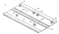
- the holding frame 3 has a receiving portion 39 to which the claw portion 28a is locked at a position facing the fixing portion 28 of the EL unit 2.
- the receiving portion 39 is a cylindrical member having an inner diameter that is larger than the outer diameter of the fixed portion 28 and smaller than the distance between the tips of the pair of biased claw portions 28a.
- claw part 28a is hooked is formed in the internal peripheral surface of the receiving part 39 (refer also FIG. 30).
- the recess 39a is tapered so as to correspond to the shape of the claw 28a.
- a spring 39b (FIG. 30B) is also provided at a portion of the receiving portion 39 that contacts the fixed surface 31.
- the concave stripes 33 a are not formed on both edge portions 33 of the holding frame 3.
- Other configurations are the same as those in the first embodiment.
- the back surface of the EL unit 2 is opposed to the front surface of the attachment portion of the holding frame 3. Then, the EL unit 2 is pushed in the vertical direction with respect to the holding frame 3. Since the claw portion 28 a is formed in a tapered shape, the claw portion 28 a is pushed into the fixed portion 28 when it comes into contact with the opening of the cylindrical receiving portion 39.
- the EL unit 2 can be easily detached from the holding frame 3 without removing the front cap 51 or the end cap 52 (see FIG. 1) from the holding frame 3. can do.
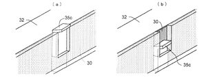
- the illumination system 1 according to this modification is provided such that the conductive member 30 is embedded in the inner side surfaces of the pair of convex portions 32 facing each other, and a part of the conductive member 30 is the convex portion 32.
- the cover member 35c is provided at the exposed portion.
- the configuration for holding the EL unit 2 on the holding frame 3 is the same as in the fourth embodiment.
- the cover member 35c is slidable in a state of being urged in a direction perpendicular to the fixed surface 31 in parallel with the inner surface of the ridge portion 32. It is configured. Further, the upper end portion of the cover member 35c is bent in a bowl shape.
- the power supply terminal 22a of the EL unit 2 is bent in an L shape toward the side of the guide block 25, and its tip protrudes from the side surface of the guide block 25.
- the power supply terminal 22a comes into contact with the upper end portion of the cover member 35c, and the cover member 35c.
- the exposed conductive member 30 and the power supply terminal 22a are electrically connected.
- the conductive member 30 is covered by the cover member 35c at the portion where the EL unit 2 of the holding frame 3 is not held, similarly to the modified examples shown in FIGS. 30 can be protected from dust and the like.
- the EL unit 2 includes a fixing portion 28 that protrudes toward the holding frame 3 on the surface facing the holding frame 3.
- the fixing portion 28 has a pair of claw portions 28a that can slide while being urged in a direction perpendicular to the protruding direction.
- the holding frame 3 has a long shape, and has a receiving strip 39c to which the claw portion 28a of the EL unit 2 is locked between both longitudinal ends thereof.
- the receiving strip 39c has a plurality of concave portions 39d and convex portions 39e formed continuously on one side surface.
- the concave portions 39d and the convex portions 39e are formed so that the surfaces that connect them are inclined surfaces, and the corner portions that connect the respective surfaces are gently rounded.
- a pair of receiving strips 39c are formed between the conductive member 30 and the two edge portions 33 so that the surfaces on which the concave portions 39d and the convex portions 39e are formed face each other.
- the positional relationship between the pair of receiving strips 39c is such that the interval between the opposed concave portions 39d is slightly wider than the interval between the tips of the pair of biased claw portions 28a, and The interval between the convex portions 39e facing each other is set to be slightly wider than the outer shape of the fixed portion 28. Further, a groove 39f on which the claw 28a is hooked is formed on the convex portion 39e.
- the EL unit 2 is opposed to the holding frame 3 so that the fixing portion 28 is positioned between the concave portions 39d facing each other in the pair of receiving strips 39c.
- the EL unit 2 is present behind the end of the holding frame 3 and that the convex portion 39e and the claw portion 28a are not opposed to each other.
- the EL unit 2 is moved to the holding frame 3 side so that the fixing portion 28 is fitted between the facing concave portions 39d.
- the EL unit 2 is slid along the longitudinal direction of the holding frame 3.
- the EL unit 2 can be easily detached from the holding frame 3 without removing the front cap 51 or the end cap 52 (see FIG. 1) from the holding frame 3 as in the second to fourth embodiments. can do.
- the EL unit 2 is slid in the longitudinal direction of the holding frame 3 to hold the EL unit 2 at an appropriate position where the convex portions 39e and the groove portions 39f are formed. Can do.
- the EL unit 2 and the holding frame 3 are connected by a wire 6.
- wire through holes are formed at positions that do not interfere when the EL unit 2 is attached to the holding frame 3.
- the wire 6 is inserted into the wire through hole and locked with a key or the like.
- Other configurations are the same as those in the first to fifth embodiments. In the example shown in the figure, the configuration described in the fifth embodiment is shown, but the configuration is not limited thereto. According to this configuration, the EL unit 2 can be easily detached from the holding frame 3, and the EL unit 2 can be prevented from being stolen with a simple configuration.
- FIGS. 39 and 40 an illumination system according to a seventh embodiment of the present invention will be described with reference to FIGS. 39 and 40 in addition to FIG. 2 described above.
- the control unit 4 and the EL unit 2 perform mutual authentication, and the control unit 4 supplies power to the EL unit 2 when the EL unit 2 is authenticated. Is configured to do.
- a specific operation of the illumination system 1 will be described.
- Phase (3) The communication and power supply are performed by periodically and regularly repeating the power supply phase.
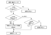
- the control unit 4 confirms whether the EL unit 2 is compatible with the illumination system 1.
- the lighting system 1 of the present embodiment performs power supply after the control unit 4 and the EL unit 2 perform mutual authentication and confirm that they are preset by the administrator. That is, the illumination system 1 of the present embodiment is different from the first embodiment in (2) authentication / configuration phase.
- the (1) monitoring (detection) phase and (2) authentication / configuration phase are the same as those in the first embodiment.
- a confirmation signal is output from the control unit 4 to the EL unit 2.
- the EL unit 2 Upon receiving this confirmation signal, the EL unit 2 outputs address information assigned to itself and information such as the rated current of the light emitting unit 20 incorporated in the EL unit 2 to the control unit 4. These pieces of information (packets) are written in the memory (main control unit 42) of the control unit 4.
- the control unit 4 Upon receiving these pieces of information, the control unit 4 authenticates that the EL unit 2 is suitable for the lighting system 1 (primary authentication).
- the control unit 4 determines that power cannot be supplied to the conductive member 30 as shown in FIG.
- the control unit 4 transmits a communication signal for confirming whether or not the EL unit 2 has the address information of the control unit 4 to the EL unit 2.
- the EL unit 2 transmits the address information to the control unit 4 when it has the address information of the control unit 4 (secondary authentication).
- the control unit 4 checks whether this address information matches its own address information (tertiary authentication). And the control unit 4 transfers to (3) electric power feeding phase, when the address information corresponds. On the other hand, if the address information does not match, it is determined that power cannot be supplied to the EL unit 2. Further, when the EL unit 2 does not have the address information of the control unit 4, the EL unit 2 writes the address information of the control unit 4 in its own memory.
- the case where the EL unit 2 does not have the address information of the control unit 4 is a case where the EL unit 2 is new or has been initialized, and the EL applied to one of the lighting systems 1 once.
- Unit 2 has some control unit 4 address information. Therefore, for example, even when an EL unit 2 stolen from another lighting system 1 is to be used in its own lighting system 1, the address information of the original control unit 4 is recorded in the EL unit 2. ing. Therefore, it does not match the address information of the control unit 4 of its own lighting system 1, and power is not supplied to the EL unit 2.
- the present embodiment As described above, power is supplied only when mutual authentication is performed between the control unit 4 and the EL unit 2, and when mutual authentication is not performed, Power is not supplied. That is, even if the EL unit 2 is stolen from another person's lighting system 1, it cannot be applied to the lighting system 1. If it carries out like this, the theft of the EL unit 2 of the other person by the user of the illumination system 1 can be suppressed as a control system at least. Although the EL unit 2 does not function alone, there is a possibility that a person who does not recognize the lighting system 1 may steal the EL unit 2. Therefore, when the lighting system 1 is installed in a place where an unspecified number of people such as commercial facilities gather, a physical anti-theft means may be provided like the wire 6 shown in the sixth embodiment. preferable.
- the control unit 4 outputs a warning signal when the EL unit 2 is detached from the holding frame 3.
- a warning alarm is used as the warning signal.
- the control unit 4 is configured not to output a warning signal when management information is input by an administrator.
- the management information here is, for example, a personal identification number input from an interface unit provided in the control unit 4.
- the operation flow in this case is shown in FIG.
- the control unit 4 does not output a warning signal when the EL unit 2 is removed only when the correct password is input within three times. In this way, the EL unit 2 can be prevented from being stolen systematically.
- the present invention is not limited to the above embodiment, and various modifications can be made.
- the configuration in which the holding frame 3 is connected only to one end portion of the front cap 51 in which the control unit 4 is housed is shown. May be linked.
- the contact portions 44 are provided at both ends of the front cap 51, and the conductive member 30 of the holding frame 3 is connected to each of them.
- the EL unit 2 connected to the two conductive members 30 is connected to one control unit. 4 may be configured to control.
Landscapes
- Engineering & Computer Science (AREA)
- General Engineering & Computer Science (AREA)
- Physics & Mathematics (AREA)
- Microelectronics & Electronic Packaging (AREA)
- Optics & Photonics (AREA)
- Electroluminescent Light Sources (AREA)
- Fastening Of Light Sources Or Lamp Holders (AREA)
- Arrangement Of Elements, Cooling, Sealing, Or The Like Of Lighting Devices (AREA)
- Non-Portable Lighting Devices Or Systems Thereof (AREA)
Abstract
L'invention vise à procurer un système d'éclairage pour réduire un espace de câblage et simplifier la construction et le remplacement de sources de lumière. A cet effet, l'invention porte sur un système d'éclairage (1), lequel système comprend une unité à électroluminescence (2) comprenant de plus une unité émettrice de lumière (20), un bâti de maintien (3) qui maintient l'unité à électroluminescence (2), et une unité de commande (4) qui commande l'allumage de l'unité à électroluminescence (2). Le bâti de maintien (3) comprend de plus un élément conducteur en forme de rail (30), et un signal d'alimentation et un signal de communication sont transmis par l'intermédiaire de l'élément conducteur (30) entre l'unité de commande (3) et l'unité à électroluminescence (2). Avec cette configuration, une connexion entre l'unité de commande (4) et l'unité à électroluminescence (2) est formée par l'élément conducteur (30) qui est disposé dans le bâti de maintien (3) qui maintient l'unité à électroluminescence, permettant une réduction d'espace pour le câblage dans un espace résidentiel. La disposition du bâti de maintien (3) dans une surface de construction et la liaison de l'unité à électroluminescence (2) et de l'unité de commande (4) dans l'unité de maintien (3) forment ces connexions, permettant à un résident d'installer le système d'éclairage (1) selon ce qui est approprié, et d'effectuer facilement un remplacement de l'unité à électroluminescence (2), sans nécessiter des compétences spéciales, etc.
Priority Applications (4)
| Application Number | Priority Date | Filing Date | Title |
|---|---|---|---|
| EP12797278.4A EP2719946A4 (fr) | 2011-06-07 | 2012-06-01 | Système d'éclairage |
| KR1020137032267A KR20140018374A (ko) | 2011-06-07 | 2012-06-01 | 조명 시스템 |
| CN201280027592.5A CN103597282A (zh) | 2011-06-07 | 2012-06-01 | 照明系统 |
| US14/123,769 US9826579B2 (en) | 2011-06-07 | 2012-06-01 | Illumination system |
Applications Claiming Priority (2)
| Application Number | Priority Date | Filing Date | Title |
|---|---|---|---|
| JP2011127095A JP5796167B2 (ja) | 2011-06-07 | 2011-06-07 | 照明システム |
| JP2011-127095 | 2011-06-07 |
Publications (1)
| Publication Number | Publication Date |
|---|---|
| WO2012169165A1 true WO2012169165A1 (fr) | 2012-12-13 |
Family
ID=47295750
Family Applications (1)
| Application Number | Title | Priority Date | Filing Date |
|---|---|---|---|
| PCT/JP2012/003634 Ceased WO2012169165A1 (fr) | 2011-06-07 | 2012-06-01 | Système d'éclairage |
Country Status (6)
| Country | Link |
|---|---|
| US (1) | US9826579B2 (fr) |
| EP (1) | EP2719946A4 (fr) |
| JP (1) | JP5796167B2 (fr) |
| KR (1) | KR20140018374A (fr) |
| CN (1) | CN103597282A (fr) |
| WO (1) | WO2012169165A1 (fr) |
Cited By (2)
| Publication number | Priority date | Publication date | Assignee | Title |
|---|---|---|---|---|
| CH709411A1 (de) * | 2014-03-26 | 2015-09-30 | Ribag Licht Ag | Leuchtelement mit Oled. |
| CN117716168A (zh) * | 2021-08-31 | 2024-03-15 | 松下知识产权经营株式会社 | 电路装置以及照明装置 |
Families Citing this family (19)
| Publication number | Priority date | Publication date | Assignee | Title |
|---|---|---|---|---|
| JP6120268B2 (ja) * | 2013-01-25 | 2017-04-26 | 国立大学法人山形大学 | 有機el発光装置 |
| JP2015173084A (ja) * | 2014-03-12 | 2015-10-01 | パイオニア株式会社 | 電力供給装置 |
| JP6271329B2 (ja) * | 2014-04-17 | 2018-01-31 | 株式会社カネカ | 矩形面発光パネルを配列載置した面状光源 |
| CN105299524B (zh) * | 2014-05-26 | 2018-06-05 | 赛尔富电子有限公司 | 一种led条形轨道灯 |
| CN104456478A (zh) * | 2014-11-28 | 2015-03-25 | 苏州市欧博锐自动化科技有限公司 | 一种灯具防盗方法 |
| JP6516221B2 (ja) | 2015-06-26 | 2019-05-22 | パナソニックIpマネジメント株式会社 | 照明装置 |
| DE102015008699B4 (de) * | 2015-07-08 | 2017-05-11 | Jenoptik Advanced Systems Gmbh | Fehlerstromsensor für eine Fehlerstrom-Schutzeinrichtung zum Überwachen eines elektrischen Verbrauchers für ein Fahrzeug |
| HK1218227A2 (zh) * | 2015-11-20 | 2017-02-03 | PanelOled Ltd. | 一种照明面板以及一种照明系统 |
| JP6731947B2 (ja) * | 2015-12-17 | 2020-07-29 | 株式会社カネカ | 照明システム及び面状光源 |
| CN106374401A (zh) * | 2016-11-08 | 2017-02-01 | 浩翔电气集团有限公司 | 地库多功能走线槽 |
| FR3068109B1 (fr) * | 2017-06-27 | 2019-10-04 | Valeo Vision | Dispositif et systeme d'eclairage pour vehicule automobile utilisant une diode electroluminescente organique |
| JP6968619B2 (ja) * | 2017-08-23 | 2021-11-17 | スタンレー電気株式会社 | 車両用灯具 |
| USD904670S1 (en) | 2018-05-08 | 2020-12-08 | Danyel Verdi | Lighting fixture accessory |
| USD904672S1 (en) | 2018-05-08 | 2020-12-08 | Danyel Verdi | Lighting fixture accessory |
| USD904671S1 (en) | 2018-05-08 | 2020-12-08 | Danyel Verdi | Lighting fixture accessory |
| USD904673S1 (en) | 2018-05-08 | 2020-12-08 | Danyel Verdi | Lighting fixture accessory |
| JP7137350B2 (ja) * | 2018-05-09 | 2022-09-14 | 積水ハウス株式会社 | 住宅用内装品、室内用作業装置、手摺装置、洗面台ユニット、框構造、並びに、梁構造 |
| DE102020131626A1 (de) * | 2020-11-30 | 2022-06-02 | Zumtobel Lighting Gmbh | Nutzung von leitungen eines lichtbandsystems für datenkommunikation |
| DE102021129983A1 (de) | 2021-11-17 | 2023-05-17 | Sven van Helden | Einrichtung zum Verschieben einer Deckenleuchte |
Citations (6)
| Publication number | Priority date | Publication date | Assignee | Title |
|---|---|---|---|---|
| JP2007034240A (ja) * | 2005-07-21 | 2007-02-08 | Yoshikawa Masumi | Elコ−ドレス点灯制御パネル |
| JP2007157361A (ja) * | 2005-11-30 | 2007-06-21 | Toshiba Lighting & Technology Corp | 非常用照明器具および防災用照明器具自動点検システム |
| JP2008193840A (ja) * | 2007-02-06 | 2008-08-21 | Nakazawa Naotsugu | 配電ダクト |
| JP2009152009A (ja) * | 2007-12-19 | 2009-07-09 | Panasonic Electric Works Co Ltd | 照明器具 |
| JP2010009886A (ja) * | 2008-06-25 | 2010-01-14 | Panasonic Electric Works Co Ltd | 照明器具 |
| JP2010225983A (ja) * | 2009-03-25 | 2010-10-07 | Konica Minolta Holdings Inc | 有機el素子、発光装置及び有機el素子の製造方法 |
Family Cites Families (21)
| Publication number | Priority date | Publication date | Assignee | Title |
|---|---|---|---|---|
| US4039820A (en) * | 1975-09-05 | 1977-08-02 | Dayton Manufacturing Company | Watertight lamp fixture |
| US5671997A (en) * | 1993-06-01 | 1997-09-30 | Potts; J. Barry | Tamper-resistant fixture for self-luminous radioactive light |
| US5775016A (en) * | 1995-07-03 | 1998-07-07 | Chien; Tseng-Lu | Illuminated safety guide |
| US6170958B1 (en) * | 1995-02-03 | 2001-01-09 | Tseng-Lu Chien | Electro-luminescent night light having an improved housing and connector arrangement therefor |
| DE29621619U1 (de) * | 1996-12-12 | 1997-02-27 | Siemens AG, 80333 München | Vorrichtung zur Beleuchtung von Theaterbühnen, TV-Studios o.dgl. |
| JP3932061B2 (ja) | 1996-12-26 | 2007-06-20 | シチズン電子株式会社 | El発光装置及びその製造方法 |
| US5724909A (en) * | 1997-02-19 | 1998-03-10 | Burke Industries, Inc. | Passive pathway marking system |
| US5941627A (en) * | 1997-04-02 | 1999-08-24 | Sacher; Dominic | Lighting conductor rail system |
| US6837591B2 (en) * | 1999-08-11 | 2005-01-04 | Tufte Brian N | Kitchen appliance with elongated light source |
| US20020159741A1 (en) * | 2001-02-26 | 2002-10-31 | Graves Stephen M. | Optical transmission tube and applications thereof |
| DE10212232A1 (de) * | 2002-03-19 | 2003-10-09 | Semperlux Ag | Stromschiene mit Datenleitung |
| US6827459B2 (en) * | 2002-03-27 | 2004-12-07 | 3M Innovative Properties Company | Lighted fastening structure |
| JP2005123178A (ja) * | 2003-09-24 | 2005-05-12 | Toshiba Lighting & Technology Corp | 照明装置 |
| JP4148908B2 (ja) * | 2004-02-16 | 2008-09-10 | 株式会社小糸製作所 | 車両用灯具 |
| US20060002102A1 (en) * | 2004-06-30 | 2006-01-05 | Leonard Stephen B | Volatile material dispensing system with illuminating device |
| JP4543962B2 (ja) * | 2005-02-28 | 2010-09-15 | パナソニック電工株式会社 | 照明装置 |
| US20070285949A1 (en) * | 2006-06-08 | 2007-12-13 | Ledtronics Inc. | LED track lighting system |
| US8328375B2 (en) * | 2006-09-29 | 2012-12-11 | Osram Opto Semiconductors Gmbh | Organic lighting device and lighting equipment |
| DE102007024422A1 (de) * | 2007-05-25 | 2008-11-27 | Cooper Crouse-Hinds Gmbh | Leuchte und Schienenmodul |
| US7806569B2 (en) * | 2007-09-28 | 2010-10-05 | Osram Sylvania Inc. | Lighting system with removable light modules |
| US8641236B2 (en) * | 2010-08-09 | 2014-02-04 | Air Motion Systems, Inc. | Insulated LED device |
-
2011
- 2011-06-07 JP JP2011127095A patent/JP5796167B2/ja not_active Expired - Fee Related
-
2012
- 2012-06-01 CN CN201280027592.5A patent/CN103597282A/zh active Pending
- 2012-06-01 US US14/123,769 patent/US9826579B2/en not_active Expired - Fee Related
- 2012-06-01 WO PCT/JP2012/003634 patent/WO2012169165A1/fr not_active Ceased
- 2012-06-01 KR KR1020137032267A patent/KR20140018374A/ko not_active Ceased
- 2012-06-01 EP EP12797278.4A patent/EP2719946A4/fr not_active Withdrawn
Patent Citations (6)
| Publication number | Priority date | Publication date | Assignee | Title |
|---|---|---|---|---|
| JP2007034240A (ja) * | 2005-07-21 | 2007-02-08 | Yoshikawa Masumi | Elコ−ドレス点灯制御パネル |
| JP2007157361A (ja) * | 2005-11-30 | 2007-06-21 | Toshiba Lighting & Technology Corp | 非常用照明器具および防災用照明器具自動点検システム |
| JP2008193840A (ja) * | 2007-02-06 | 2008-08-21 | Nakazawa Naotsugu | 配電ダクト |
| JP2009152009A (ja) * | 2007-12-19 | 2009-07-09 | Panasonic Electric Works Co Ltd | 照明器具 |
| JP2010009886A (ja) * | 2008-06-25 | 2010-01-14 | Panasonic Electric Works Co Ltd | 照明器具 |
| JP2010225983A (ja) * | 2009-03-25 | 2010-10-07 | Konica Minolta Holdings Inc | 有機el素子、発光装置及び有機el素子の製造方法 |
Non-Patent Citations (1)
| Title |
|---|
| See also references of EP2719946A4 * |
Cited By (2)
| Publication number | Priority date | Publication date | Assignee | Title |
|---|---|---|---|---|
| CH709411A1 (de) * | 2014-03-26 | 2015-09-30 | Ribag Licht Ag | Leuchtelement mit Oled. |
| CN117716168A (zh) * | 2021-08-31 | 2024-03-15 | 松下知识产权经营株式会社 | 电路装置以及照明装置 |
Also Published As
| Publication number | Publication date |
|---|---|
| US20140111094A1 (en) | 2014-04-24 |
| EP2719946A1 (fr) | 2014-04-16 |
| JP2012252982A (ja) | 2012-12-20 |
| EP2719946A4 (fr) | 2015-03-04 |
| CN103597282A (zh) | 2014-02-19 |
| JP5796167B2 (ja) | 2015-10-21 |
| KR20140018374A (ko) | 2014-02-12 |
| US9826579B2 (en) | 2017-11-21 |
Similar Documents
| Publication | Publication Date | Title |
|---|---|---|
| JP5796167B2 (ja) | 照明システム | |
| US9400095B2 (en) | Lighting apparatus | |
| US20140055990A1 (en) | Solid state hospitality lamp | |
| JP5945725B2 (ja) | 照明装置およびそれを用いた照明装置ユニット | |
| US20160190735A1 (en) | Low voltage buss system | |
| JP2009157651A (ja) | 配線器具 | |
| US10683976B2 (en) | Illumination device and attachment member | |
| KR101976596B1 (ko) | 매립형 IoT 조명 스위치 장치 | |
| EP2495491B1 (fr) | Dispositif d'illumination | |
| JP5853193B2 (ja) | ワイヤレス受信器 | |
| WO2009081985A1 (fr) | Crochet de plafond | |
| JP2021106155A (ja) | 収納装置 | |
| JP2009146827A (ja) | 直流コンセント | |
| JP6653468B2 (ja) | 制御装置 | |
| JP2009158299A (ja) | 引掛シーリング | |
| JP2017011219A (ja) | 制御装置 | |
| JP2016072018A (ja) | 電灯装置 | |
| CN105210243A (zh) | 无线连接器节点和系统 | |
| KR20140073619A (ko) | 조명 장치 및 조명 제어 방법 | |
| CN101316488B (zh) | 控制盘装置 | |
| CN213777390U (zh) | 一种发光组件及其显示装置 | |
| CN108039611A (zh) | 一种插座结构与智能插座 | |
| ES2586596B1 (es) | Dispositivo de indicación, comunicación, alimentación eléctrica, medición y/o control de instalaciones | |
| JP2009265523A (ja) | 保持具及び表示装置 | |
| WO2017049062A1 (fr) | Système de bus basse tension |
Legal Events
| Date | Code | Title | Description |
|---|---|---|---|
| 121 | Ep: the epo has been informed by wipo that ep was designated in this application |
Ref document number: 12797278 Country of ref document: EP Kind code of ref document: A1 |
|
| WWE | Wipo information: entry into national phase |
Ref document number: 14123769 Country of ref document: US |
|
| ENP | Entry into the national phase |
Ref document number: 20137032267 Country of ref document: KR Kind code of ref document: A |
|
| NENP | Non-entry into the national phase |
Ref country code: DE |