WO2012169335A1 - Système de climatisation pour véhicule - Google Patents
Système de climatisation pour véhicule Download PDFInfo
- Publication number
- WO2012169335A1 WO2012169335A1 PCT/JP2012/062820 JP2012062820W WO2012169335A1 WO 2012169335 A1 WO2012169335 A1 WO 2012169335A1 JP 2012062820 W JP2012062820 W JP 2012062820W WO 2012169335 A1 WO2012169335 A1 WO 2012169335A1
- Authority
- WO
- WIPO (PCT)
- Prior art keywords
- opening
- bypass
- heater
- foot
- door
- Prior art date
- Legal status (The legal status is an assumption and is not a legal conclusion. Google has not performed a legal analysis and makes no representation as to the accuracy of the status listed.)
- Ceased
Links
Images






Classifications
-
- B—PERFORMING OPERATIONS; TRANSPORTING
- B60—VEHICLES IN GENERAL
- B60H—ARRANGEMENTS OF HEATING, COOLING, VENTILATING OR OTHER AIR-TREATING DEVICES SPECIALLY ADAPTED FOR PASSENGER OR GOODS SPACES OF VEHICLES
- B60H1/00—Heating, cooling or ventilating devices
- B60H1/00007—Combined heating, ventilating, or cooling devices
- B60H1/00021—Air flow details of HVAC devices
- B60H1/00035—Air flow details of HVAC devices for sending an air stream of uniform temperature into the passenger compartment
- B60H1/0005—Air flow details of HVAC devices for sending an air stream of uniform temperature into the passenger compartment the air being firstly cooled and subsequently heated or vice versa
-
- B—PERFORMING OPERATIONS; TRANSPORTING
- B60—VEHICLES IN GENERAL
- B60H—ARRANGEMENTS OF HEATING, COOLING, VENTILATING OR OTHER AIR-TREATING DEVICES SPECIALLY ADAPTED FOR PASSENGER OR GOODS SPACES OF VEHICLES
- B60H1/00—Heating, cooling or ventilating devices
- B60H1/00642—Control systems or circuits; Control members or indication devices for heating, cooling or ventilating devices
- B60H1/00814—Control systems or circuits characterised by their output, for controlling particular components of the heating, cooling or ventilating installation
- B60H1/00821—Control systems or circuits characterised by their output, for controlling particular components of the heating, cooling or ventilating installation the components being ventilating, air admitting or air distributing devices
- B60H1/00835—Damper doors, e.g. position control
- B60H1/00842—Damper doors, e.g. position control the system comprising a plurality of damper doors; Air distribution between several outlets
Definitions
- the present invention relates to a vehicle air conditioner capable of setting the temperature of blown air blown out from a blow-out port to a vehicle interior to an appropriate temperature.
- a vehicle air conditioner in addition to blowing air from an arbitrary outlet or blowing out conditioned air from a desired outlet, it is required to blow out air at an appropriate temperature according to the outlet. It is done. Further, general requirements include miniaturization, weight reduction, and easy temperature adjustment.
- an air conditioner for a vehicle constitutes a part of a refrigeration cycle with a blower that forms blown air and an evaporator (evaporator) that forms cold air by exchanging heat between a low-temperature refrigerant and the blown air.
- a heater (heater core) that is arranged downstream of the evaporator and reheats the cold air formed by the evaporator to form hot air.
- Hot water warmed by exhaust heat from the engine flows through the heater, and is constant at about 90 ° C. in a steady state.
- the ratio of the air that is reheated through the heater out of the cold air that has passed through the evaporator is controlled by the opening degree of the temperature control means (mix door).
- the warm air that has been reheated through the air and the cold air that has not passed through the heater are uniformly mixed in the mixing chamber (mix space) to create air at a predetermined temperature.
- the mix door needs to be able to control the distribution of the air that has passed through the evaporator to the heater in the range of 0 to 100%.
- the wind blown from the vent outlet provided on the upper body side of the occupant and the wind blown from the foot outlet provided on the foot side of the occupant There is a request to add a temperature difference to the air and to make the temperature of the wind blown from the vent outlet relatively lower than the temperature of the wind blown from the foot outlet (request to make a temperature difference above and below the passenger compartment) is there.
- Patent Document 1 There has been proposed a vehicle air conditioner that can provide a temperature difference between the upper and lower sides of a passenger compartment (see, for example, Patent Document 1).
- an auxiliary cold air bypass passage is provided for passing cool air that bypasses the heater in the direction of the face opening, and the auxiliary cold air bypass passage is opened and the face opening is closed in the blowing mode in which the face opening is opened.
- a technique has been disclosed in which a relatively cool cool air can be sent to the occupant's head and chest even when the temperature of the air blown out from the feet of the occupant is set high by closing the auxiliary cold air bypass passage in the mode. .
- a mix door is disposed between the evaporator and the heater.
- a configuration in which the mix door is arranged downstream of the heater instead of between the evaporator and the heater is conceivable.
- the mix door needs to be disposed between the evaporator and the heater so as to block the front surface of the heater.
- both the adjustment of the temperature by the mix door arranged between the evaporator and the heater and the provision of a temperature difference between the upper and lower when blowing out in the bi-level mode are the adjustment of the air distribution ratio by the mix door and
- delicate adjustment tilting
- the desired upper and lower temperature difference cannot be imparted.
- An object of the present invention is to provide a vehicle air conditioner that can be reduced in size and weight and that can easily adjust the temperature difference between the upper and lower sides.
- the vehicle air conditioner according to the present invention forms an air flow path, and on the downstream side of the air flow path, a defroster opening connected to the defroster outlet, a vent opening connected to the vent outlet, and a foot outlet
- the relative positional relationship between the heater and the bypass flow path is such that the heater is closer to the foot opening and the bypass flow path is farther away. Preferably it is. A temperature difference between the upper and lower sides of the passenger compartment can be more reliably applied.
- the bypass control means when the heater is operated and the bi-level mode in which both the vent opening and the foot opening are open, the bypass control means causes the bypass flow path to pass through. It is preferable to output a signal for opening.
- the bi-level mode the temperature difference between the upper and lower sides of the passenger compartment can be more reliably applied.
- the heater operates and the defroster mode in which the defroster opening opens, the vent mode in which the vent opening opens, the foot mode in which the foot opening opens or the In the differential / foot mode in which both the defroster opening and the foot opening are open
- the bypass control means preferably outputs a signal for closing the bypass flow path.
- the bypass control means outputs a signal for opening the bypass flow path when the heater is not operating. At the time of cooling or blowing, the air resistance can be reduced to increase the blowing amount.
- the vehicle air conditioner it is preferable to further include one link mechanism that links the bypass control means and the blowout outlet control means.
- the number of parts can be reduced.
- the heater is preferably an electric heating type.
- the amount of heat generated by the heater can be adjusted to produce air at a predetermined temperature.
- the heater is a heat pump cycle radiator, and the heat pump cycle compressor including the radiator is a variable capacity type or an electric type.
- the circulation amount of the refrigerant By controlling the circulation amount of the refrigerant, the amount of heat generated by the heater can be adjusted, and air at a predetermined temperature can be created.
- the compressor of the refrigeration cycle including the evaporator is preferably a variable capacity type or an electric type.
- the amount of circulating refrigerant By controlling the amount of circulating refrigerant, the amount of heat absorbed by the evaporator can be adjusted, and air at a predetermined temperature can be created.
- the present invention can provide a vehicle air conditioner that can be reduced in size and weight, and that can easily adjust the temperature difference between the upper and lower sides.
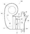
- FIG. 1 is a schematic diagram showing an example of a vehicle air conditioner according to the present embodiment.
- the vehicle air conditioner 100 forms an air flow path 10, and on the downstream side of the air flow path 10, a defroster opening 12 connected to a defroster air outlet (not shown), a vent air outlet (not)
- a case 40 having a vent opening 13 connected to an illustration (not shown) and a foot opening 14 connected to a foot outlet (not shown), a blower 30 for forming an air flow 31 in the air flow path 10, and an air flow path 10, the evaporator 5 disposed in the downstream side of the evaporator 5, the heater 6 always passing the air flow 32 when the blower 30 is in operation, and the bypass flow bypassing the heater 6.
- bypass door 21 Passes through the path 11, the bypass door 21 that opens and closes the bypass passage 11, the bypass control means (not shown) that controls the opening and closing of the bypass door 21, the defroster opening 12, the vent opening 13, and the foot opening 14. That comprises outlet control means for controlling the distribution of air volume (not shown).
- the case 40 has an air flow path 10 therein, and at least the evaporator 5 and the heater 6 are arranged in the air flow path 10 to send HVAC air whose temperature is adjusted into the vehicle interior. This is the case.
- An outside air inlet (not shown) and an inside air inlet (not shown) are provided on the most upstream side of the air flow path 10.
- the outside air inlet and the inside air inlet are selectively opened and closed by switching an intake door (not shown), and the air introduced into the air flow path 10 can be selected as outside air, inside air, or inside / outside air mixed air. ing.
- the blower 30 has a drive motor and a fan, and rotates the fan by driving the drive motor and sucks air to form an air flow 31 in the air flow path 10.
- the air flow 31 passes through the evaporator 5 after passing through a filter (not shown).
- the vehicle air conditioner 100 includes a refrigeration cycle 1.
- the refrigeration cycle 1 includes at least a compressor 2, an outdoor heat exchanger 3, a refrigerant expansion means 4, and an evaporator 5.
- the compressor (compressor) 2 receives the driving force from the engine or the driving force of a motor driven by electric power, compresses the low-temperature and low-pressure vaporized refrigerant into a high-temperature and high-pressure vaporized refrigerant. To do.
- the compressor 2 is preferably a variable capacity type or an electric type.
- the variable capacity compressor is a compressor that changes the capacity of refrigerant to be discharged.
- the type of the variable capacity compressor is not particularly limited, and examples thereof include a swash plate type, a wobble type, a vane type, and a scroll type.
- EDC Electric Driver Compressor
- An electric compressor is a compressor that sucks, compresses, and discharges a refrigerant by being driven by an electric motor. Therefore, since the rotation speed is not affected by the engine speed, the temperature of the evaporator 5 can be adjusted with higher accuracy.
- an electric compressor may be mounted on a hybrid vehicle (HEV, Hybrid Electric Vehicle) because the engine may stop during operation.
- an electric vehicle Electric Vehicle
- an electric compressor is mounted.
- the outdoor heat exchanger 3 exchanges heat between the refrigerant flowing inside and the outside air or running air taken in by a cooling fan (not shown) disposed in the vicinity of the outdoor heat exchanger 3.
- the refrigerant expansion means 4 converts the high-temperature and high-pressure liquefied refrigerant into a low-temperature and low-pressure gas-liquid mixed refrigerant by a throttling action.
- the evaporator (evaporator) 5 exchanges heat between the refrigerant flowing inside and the air flow 31 passing through the evaporator 5.
- the refrigeration cycle 1 shown in FIG. 1 operates as follows.
- the high-temperature and high-pressure vaporized refrigerant discharged from the compressor 2 flows into the outdoor heat exchanger 3.
- the refrigerant exchanges heat with outside air or traveling wind passing through the outdoor heat exchanger 3, and becomes a high-temperature and high-pressure liquefied refrigerant.
- this refrigerant passes through the refrigerant expansion means 4, it becomes a low-temperature low-pressure gas-liquid mixed refrigerant and flows into the evaporator 5.
- the refrigerant exchanges heat with the air flow 31 passing through the evaporator 5 to become a low-temperature and low-pressure vaporized refrigerant and is sucked into the compressor 2.
- the air flow 32 that has passed through the evaporator 5 is cooled and dehumidified air, and is used for cooling or dehumidifying the passenger compartment.
- the air flow 32 that has passed through the evaporator 5 passes through the heater 6.
- the heater (heater core) 6 reheats the air of the air flow 32 that has passed through the evaporator 5.
- the heater 6 is, for example, a hot water heater using engine cooling water heated by engine exhaust heat, an electric heating heater having a heating element, or a radiator using hot gas of a heat pump cycle. .
- a known heating wire such as a PTC (Positive Temperature Coefficient) element is used as a heating element.
- the air flow 32 always passes through the heater 6. That is, there is no mix door upstream of the heater 6. Therefore, the evaporator 5 and the heater 6 can be brought close to each other, and the vehicle air conditioner 100 can be reduced in size and weight. Furthermore, as described in paragraph [0044], since the air of a predetermined temperature can be created by having temperature control means (not shown) for controlling the temperature of the heater 6, conventional vehicle air conditioners Thus, a large-capacity mix space for mixing the warm air reheated after passing through the heater and the cool air not passing through the heater is unnecessary, and the case 40 can be further miniaturized.
- the bypass channel 11 is a part of the air channel 10 and is a channel that bypasses the heater 6.
- the bypass channel 11 is opened and closed by a bypass door 21. Adjustment of the opening degree of the bypass door 21 is performed by a bypass control means (not shown).
- the bypass control means has a drive unit (not shown) that drives the bypass door 21 and a control unit (not shown) that controls the drive unit.
- the drive unit is, for example, a servo motor.
- the control unit is, for example, an ECU (Electronic Control Unit) including a CPU as a central processing unit.
- the ECU receives a blowing mode or set temperature signal from an operation panel (not shown) performed by the occupant, or sensor signals from various sensors such as an outside air temperature sensor, a vehicle interior temperature sensor, or a solar radiation amount sensor, and determines the blowing mode. And the target position of the bypass door 21 is calculated and an output signal is transmitted. Then, the servo motor adjusts the opening degree of the bypass door 21 by rotationally displacing to a predetermined angle based on the output signal.
- a defroster (DEF) opening 12, a vent (VENT) opening 13, and a foot (FOOT) opening 14 are provided on the downstream side of the air flow path 10.
- the DEF opening 12 is connected to a DEF outlet (not shown) provided in the vehicle interior via a DEF duct (not shown).
- the DEF outlet is an outlet for blowing wind toward the inner surface of the window glass in front of the vehicle.
- the VENT opening 13 is also called a FACE opening, and is connected to a VENT outlet (not shown) provided in the vehicle compartment via a VENT duct (not shown).
- the VENT outlet is an outlet for blowing wind toward the upper body of the occupant.
- the VENT air outlet usually has a center vent air outlet provided at the center in the vehicle width direction and side vent air outlets provided on the left and right in the vehicle width direction.
- the FOOT opening 14 is connected to a FOOT outlet (not shown) provided in the vehicle compartment via a FOOT duct (not shown).
- the FOOT air outlet is an air outlet for blowing out wind toward the feet of the passenger.
- the DEF opening 12, the VENT opening 13, or the FOOT opening 14 are opened and closed by the DEF door 22, the VENT door 23, or the FOOT door 24, respectively.
- the type of the DEF door 22, the VENT door 23, or the FOOT door 24 is a plate door in FIG. This embodiment is not limited to the type of door.
- the type of door is, for example, a film door, a rotary door, a slide door, or a butterfly door in addition to a plate door. Adjustment of the opening degree of the DEF door 22, the VENT door 23, or the FOOT door 24 is performed by an outlet control means (not shown).
- the air outlet control means controls the distribution of the air volume passing through each opening according to the passenger's request or the temperature distribution in the passenger compartment.
- the outlet control means has the same basic configuration as the bypass control means. That is, the ECU receives a blowing mode or set temperature signal from an operation panel (not shown) performed by the occupant or sensor signals from various sensors, calculates the blowing mode and calculates the target position of the bypass door 21 and outputs it. Send a signal. Based on the output signal, the air outlet control means rotationally displaces a servo motor (not shown) that drives the DEF door 22, the VENT door 23, or the FOOT door 24 to a predetermined angle, whereby the DEF door 22, The opening degree of the VENT door 23 or the FOOT door 24 is adjusted.
- the opening degree of the DEF door 22, the VENT door 23, or the FOOT door 24 may be individually controlled by a servo motor provided in each door, or may be simultaneously controlled by one servo motor.
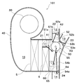
- FIG. 2 is a schematic diagram showing an example of a link mechanism.
- the vehicle air conditioner 101 preferably further includes one link mechanism 50 that links the bypass control means and the outlet control means.
- the link mechanism 50 By controlling the bypass control means and the outlet control means with one link mechanism 50, the number of parts can be reduced.
- a main link 55 connected to a servo motor 60 as a drive source via a rod 65 as a transmission means, and a bypass door opening / closing lever 51a fixed to the shaft portion R1 of the bypass door 21.
- the link mechanism 50 should just be able to make a bypass control means and an air outlet control means interlock
- the blowing mode is, for example, a DEF mode in which the DEF opening 12 mainly opens, a VENT mode in which the VENT opening 13 mainly opens, a FOOT mode in which the FOOT opening 14 mainly opens, the VENT opening 13 and the FOOT opening.
- 14 is a bi-level mode (B / L mode) in which both open, or a differential / foot mode (D / F mode) in which both the DEF opening 12 and the FOOT opening 14 are open.
- the air flow 31 passes through the evaporator 5 and becomes a cooled and dehumidified air flow 32.
- the air flow 32 is only the air flow 33 that has passed through the heater 6 when the bypass flow path 11 is closed, and the air flow 33 that has passed through the heater 6 and the bypass flow path 11 when the bypass flow path 11 is open. It is divided into an air flow 34 that has passed.
- the air flow 33 and the air flow 34 are sent to the DEF opening 12, the VENT opening 13, or the FOOT opening 14 depending on the blowing mode, and are blown into the vehicle interior.
- a temperature control means for controlling the temperature of the evaporator 5 and a temperature control means (not shown) for controlling the temperature of the heater 6 are provided. It is preferable to have.
- the temperature adjustment of the air blown into the passenger compartment can be performed without using the air mix door. 6 can be performed by adjusting each temperature.
- the temperature control means of the evaporator 5 is preferably a control device for the compressor 2, for example.
- the amount of heat absorbed can be controlled by adjusting the capacity of the refrigerant flowing into the evaporator 5 without using complicated control means.
- the temperature control means of the heater 6 may be, for example, a flow rate control valve (not shown) provided upstream of the heater 6 in the engine cooling water flow path. preferable.
- the flow rate control valve can control the temperature of the heater 6 by controlling the flow rate of the hot water flowing inside the heater 6.
- the temperature control means of the heater 6 is, for example, a pulse width modulation (PWM) control device.
- PWM pulse width modulation
- the PWM control device can control the temperature of the heater 6 by controlling the amount of heat generated by the heating element.
- the temperature control means of the heater 6 is preferably a control device of the compressor 2, for example.
- the capacity of the refrigerant flowing into the radiator 7 can be adjusted, and the temperature of the radiator 7 can be controlled. In this way, by using a variable capacity or electric compressor or an electric heating heater, complicated control is unnecessary, and the temperature of the air blown into the passenger compartment more easily and accurately. Adjustments can be made.
- FIG. 3 is a schematic diagram showing a modification of the vehicle air conditioner according to the present embodiment.
- the vehicle air conditioner 100a shown in FIG. 3 has a configuration in which a heat pump cycle radiator 7 is used as a heater.
- the heater is the heat pump cycle radiator 7, and the heat pump cycle compressor 2 including the radiator 7 may be a variable capacity type or an electric type. preferable.
- an electric heating type heater 6 may be used as an auxiliary heater if necessary.
- the heater 6 showed the form which is an electric heating type, it can change into a warm water type.
- the refrigeration cycle 1a shown in FIG. 3 includes at least the compressor 2, the outdoor heat exchanger 3, the refrigerant expansion means 4, the evaporator 5, the radiator 7, the first switching valve 9a, and the second switching valve. 9b and a four-way valve 8 are provided.
- the compressor 2 is a variable capacity or electric compressor.
- the outdoor heat exchanger 3, the refrigerant expansion means 4, and the evaporator 5 are the same as those described as the constituent elements of the refrigeration cycle 1 shown in FIG.
- the 1st switching valve 9a is arrange
- the 2nd switching valve 9b is arrange
- the four-way valve 8 switches the supply direction of the refrigerant discharged from the compressor 2 and the suction direction of the refrigerant sucked into the compressor 2.
- the temperature of the air blown into the passenger compartment is adjusted as follows.
- the four-way valve 8 is set as shown by the solid line in FIG. Further, the refrigerant flow path is switched to a flow path between the refrigerant expansion means 4 and the evaporator 5 by the first switching valve 9a, and the refrigerant flow path is switched between the evaporator 5 and the compressor 2 by the second switching valve 9b. Switch to the flow path that circulates between. Then, the high-temperature and high-pressure vaporized refrigerant discharged from the compressor 2 flows in the direction of arrow F and flows into the outdoor heat exchanger 3. Here, the refrigerant exchanges heat with outside air or traveling wind passing through the outdoor heat exchanger 3, and becomes a high-temperature and high-pressure liquefied refrigerant.
- this refrigerant passes through the refrigerant expansion means 4, it becomes a low-temperature low-pressure gas-liquid mixed refrigerant and flows into the evaporator 5.
- the refrigerant exchanges heat with the air flow 31 passing through the evaporator 5 to become a low-temperature and low-pressure vaporized refrigerant and is sucked into the compressor 2.
- the flow rate of the refrigerant flowing into the evaporator 5 is adjusted by the variable capacity or electric compressor 2.
- the air flow 32 that has passed through the evaporator 5 becomes cold air whose temperature is adjusted, and is used for cooling the passenger compartment.
- the four-way valve 8 is set as shown by the dotted line in FIG. Furthermore, the second switching valve 9b switches the refrigerant flow path to a flow path that circulates between the compressor 2 and the radiator 7, and the first switching valve 9a switches the refrigerant flow path between the radiator 7 and the refrigerant expansion means 4. Switch to the flow path that circulates between. Then, the high-temperature and high-pressure liquefied refrigerant discharged from the compressor 2 flows in the direction of the arrow F and is supplied to the radiator 7. Here, the refrigerant exchanges heat with the air flow 32 passing through the radiator 7 and becomes a high-temperature and high-pressure liquefied refrigerant.
- this refrigerant passes through the refrigerant expansion means 4, it becomes a low-temperature and low-pressure gas-liquid mixed refrigerant and flows into the outdoor heat exchanger 3.
- the refrigerant exchanges heat with the outside air or traveling wind passing through the outdoor heat exchanger 3 to become a refrigerant in a vaporized state at low temperature and low pressure, and is sucked into the compressor 2.
- the flow rate of the refrigerant flowing into the radiator 7 is adjusted by the variable capacity or electric compressor 2.
- the air flow 33 that has passed through the radiator 7 becomes warm air whose temperature is adjusted, and is further warmed by the heater 6 as necessary, and is used for heating the passenger compartment.
- a variable displacement or electric compressor complicated control is unnecessary, and the temperature of the air blown into the vehicle compartment can be adjusted more easily and accurately.
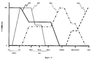
- FIG. 4 is a diagram showing opening patterns of the DEF door, the VENT door, the FOOT door, and the bypass door in the vehicle air conditioner according to the present embodiment.
- symbol D21 indicates the opening degree of the bypass door
- symbol D22 indicates the opening degree of the DEF door
- symbol D23 indicates the opening degree of the VENT door
- symbol D24 indicates the pattern of the opening degree of the FOOT door 24.
- FIG. 5 is a schematic diagram illustrating an example of a vehicle air conditioner according to the present embodiment, and is a diagram for explaining the B / L mode.
- the B / L mode is, for example, when the occupant is requesting head cold foot heat.
- the outlet control means outputs a signal for closing the DEF opening 12 and opening the VENT opening 13 and the FOOT opening 14.
- the opening degree D22 of the DEF door is 0% (fully closed).
- the opening D23 of the VENT door is preferably more than 0% and not more than 100%, and more preferably 40 to 60%.
- the opening D24 of the FOOT door is preferably more than 0% and not more than 100%, and more preferably 40 to 60%.
- a bypass control means (not shown) outputs a signal for opening the bypass flow path 11.
- the opening D21 of the bypass door is preferably more than 0% and not more than 100%, and more preferably 50 to 100%.
- the B / L mode preferably has a mode in which the opening degree D21 of the bypass door is changed, such as a B / L1 mode, a B / L2 mode, or a B / L3 mode.
- the opening degree D21 of the bypass door is almost fully opened. Accordingly, it is possible to blow out cold air from the VENT outlet and blow out hot air from the FOOT outlet to further increase the temperature difference between the upper and lower sides of the passenger compartment.
- the B / L1 mode is a mode that is selected when the sunlight is strong, for example, in winter.
- the opening D21 of the bypass door is made smaller than that in the B / L1 mode.
- the B / L2 mode is a mode that is selected when the temperature difference between the upper and lower sides of the passenger compartment may be smaller than that in the B / L1 mode.
- the opening D21 of the bypass door is made smaller than in the B / L2 mode.
- the B / L3 mode is a mode that is selected when the temperature difference between the upper and lower sides of the passenger compartment is not so necessary.
- the opening D21 of the bypass door in each mode is not particularly limited.
- the opening D21 of the bypass door is, for example, more than 70% and 100% or less
- the bypass door in the B / L2 mode, the bypass door The door opening D21 is, for example, more than 30% and 70% or less.
- the opening D21 of the bypass door is, for example, more than 0% and 30% or less.
- the relative positional relationship between the heater 6 and the bypass passage 11 is closer to the heater 6 than the foot opening 14. It is preferable that the bypass channel 11 is disposed far away.
- the air flow 34 that has passed through the bypass channel 11 is more reliably supplied to the VENT opening 13, and the air flow 33 that has passed the heater 6 is more reliably supplied to the FOOT opening 14. Can blow. And there is no possibility of reducing the temperature difference between the wind blown from the VENT outlet and the wind blown from the FOOT outlet.
- FIG. 6 is a schematic diagram illustrating an example of a vehicle air conditioner according to the present embodiment, and is a diagram for explaining a DEF mode.
- the outlet control means outputs a signal for opening the DEF opening 12 and closing the VENT opening 13 and the FOOT opening 14.
- the opening degree D22 of the DEF door is 100% (fully open).
- the opening D23 of the VENT door and the opening D24 of the FOOT door are 0% (fully closed).
- a bypass control means (not shown) outputs a signal for closing the bypass flow path 11. As shown in FIG.
- the opening D21 of the bypass door is 0% (fully closed).
- heating as hot air is performed as shown in FIG.
- the air flow 33 that has passed through the vessel 6 is blown to the DEF opening 12. Then, warm air can be blown out from the DEF outlet to prevent the windshield from fogging.
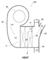
- FIG. 7 is a schematic diagram illustrating an example of a vehicle air conditioner according to the present embodiment, and is a diagram for explaining a VENT mode.
- the outlet control means outputs a signal for closing the DEF opening 12 and the FOOT opening 14 and opening the VENT opening 13.
- the opening degree D22 of the DEF door and the opening degree D24 of the FOOT door are 0% (fully closed).
- the opening D23 of the VENT door is 100% (fully open).
- a bypass control means (not shown) outputs a signal for closing the bypass flow path 11. As shown in the V1 mode of FIG.
- the opening D21 of the bypass door is 0% (fully closed).
- heating as hot air is performed as shown in FIG.
- the air flow 33 that has passed through the vessel 6 is blown to the VENT opening 13. And warm air can be blown out toward a passenger
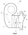
- FIG. 8 is a schematic diagram illustrating an example of a vehicle air conditioner according to the present embodiment, and is a diagram for explaining a FOOT mode.
- FOOT mode for example, the occupant is requesting wind toward his / her feet.
- the outlet control means outputs a signal for closing the DEF opening 12 and the VENT opening 13 and opening the FOOT opening 14.
- the opening degree D22 of the DEF door and the opening degree D23 of the VENT door are 0% (fully closed).
- the opening degree D24 of the FOOT door is 100% (fully open).
- a bypass control means (not shown) outputs a signal for closing the bypass flow path 11. As shown in FIG.
- the opening D21 of the bypass door is 0% (fully closed).
- heating as hot air is performed as shown in FIG.
- the air flow 33 that has passed through the vessel 6 is blown to the FOOT opening 14. And a warm air can be blown out from a FOOT blower outlet, and a passenger
- FIG. 9 is a schematic diagram illustrating an example of a vehicle air conditioner according to the present embodiment, and is a diagram for explaining a DEF / FOOT mode.
- DEF / FOOT D / F
- the outlet control means outputs a signal for opening the DEF opening 12 and the FOOT opening 14 and closing the VENT opening 13.
- the opening degree D22 of the DEF door is preferably more than 0% and not more than 100%, and more preferably 40-60%.
- the opening D23 of the VENT door is 0% (fully closed).
- the opening D24 of the FOOT door is preferably more than 0% and not more than 100%, and more preferably 40 to 60%.
- a bypass control means (not shown) outputs a signal for closing the bypass flow path 11.
- the opening D21 of the bypass door is 0% (fully closed).
- heating as warm air is performed as shown in FIG.
- the air flow 33 that has passed through the vessel 6 is blown to the DEF opening 12 and the FOOT opening 14. Then, warm air is blown out from the DEF air outlet to prevent the windshield from being fogged, and hot air is blown out from the FOOT air outlet to warm the feet of the passenger.
- FIG. 10 is a schematic diagram illustrating an example of a vehicle air conditioner according to the present embodiment, and is a diagram for explaining cooling or blowing.
- FIG. 10 shows a case where the blowing mode is the VENT mode.
- the heater 6 is not operating, for example, when the occupant is requesting cooling or when only air is required.
- the bypass control means preferably outputs a signal for opening the bypass flow path 11.
- the opening D21 of the bypass door is preferably more than 0% and not more than 100%. More preferably, it is set to 100%. Thereby, at the time of cooling or blowing, the air resistance can be reduced and the amount of blowing can be increased.
- the opening degree D21 of the bypass door is 0 when the heater 6 is not operating, as in the V2 mode. It is preferable that it exceeds 100% and is 100% or less. More preferably, it is 100%.
- FIG. 11 is a schematic diagram showing a modification of the vehicle air conditioner according to the embodiment.
- FIGS. 1 to 3 and FIGS. 5 to 10 show the form in which the evaporator 5 and the heater 6 are arranged in parallel, but in this embodiment, the heater 6 is inclined and arranged as shown in FIG. Also good. By arranging in this way, the case 40 can be further downsized.
- the bypass door 21 is provided above the heater 6 or the radiator 7, but the bypass door 21 bypasses the heater 6 or the radiator 7. Can be provided as long as the desired upper and lower temperature difference can be given when the channel is opened and opened. For example, it may be disposed below or on the side of the heater 6 or the radiator 7.
Landscapes
- Physics & Mathematics (AREA)
- Thermal Sciences (AREA)
- Engineering & Computer Science (AREA)
- Mechanical Engineering (AREA)
- Air-Conditioning For Vehicles (AREA)
Abstract
Le but de la présente invention est de proposer un système de climatisation pour véhicule plus compact, plus léger et permettant d'effectuer facilement des réglages pour augmenter ou réduire la température. Ce système de climatisation pour véhicule (100) comprend : un boîtier (40) qui forme un conduit d'air (10) et, en aval de ce conduit d'air, un orifice de désembuage (12) relié à la sortie d'un dispositif de désembuage, un orifice à hauteur de tête (13) connecté à une sortie à hauteur de tête, et un orifice à hauteur de pied (14) connecté à une sortie à hauteur de pied; un ventilateur (30) qui induit un courant d'air (31) dans le conduit; un évaporateur (5) placé dans le conduit d'air; un dispositif de chauffage (6) monté en aval de l'évaporateur et à travers lequel un flux d'air (32) passe en permanence lorsque le ventilateur fonctionne; un conduit de dérivation (11) qui contourne le dispositif de chauffage; une porte de dérivation (21) qui ouvre et ferme le conduit de dérivation; une commande de dérivation qui commande l'ouverture et la fermeture de la porte de dérivation; et une commande de sortie qui commande la distribution de la quantité d'air qui traverse l'ouverture de désembuage, l'orifice à hauteur de tête, et l'orifice à hauteur de pied.
Applications Claiming Priority (2)
| Application Number | Priority Date | Filing Date | Title |
|---|---|---|---|
| JP2011-129204 | 2011-06-09 | ||
| JP2011129204 | 2011-06-09 |
Publications (1)
| Publication Number | Publication Date |
|---|---|
| WO2012169335A1 true WO2012169335A1 (fr) | 2012-12-13 |
Family
ID=47295904
Family Applications (1)
| Application Number | Title | Priority Date | Filing Date |
|---|---|---|---|
| PCT/JP2012/062820 Ceased WO2012169335A1 (fr) | 2011-06-09 | 2012-05-18 | Système de climatisation pour véhicule |
Country Status (1)
| Country | Link |
|---|---|
| WO (1) | WO2012169335A1 (fr) |
Cited By (1)
| Publication number | Priority date | Publication date | Assignee | Title |
|---|---|---|---|---|
| CN109677229A (zh) * | 2017-10-18 | 2019-04-26 | 郑州宇通客车股份有限公司 | 加热装置及使用该装置的除霜器、车辆 |
Citations (5)
| Publication number | Priority date | Publication date | Assignee | Title |
|---|---|---|---|---|
| JPH01156125A (ja) * | 1987-12-11 | 1989-06-19 | Diesel Kiki Co Ltd | 車両用空調装置 |
| JPH0752636A (ja) * | 1993-08-16 | 1995-02-28 | Zexel Corp | 車両用ヒートポンプ空調装置 |
| JPH07108816A (ja) * | 1993-10-15 | 1995-04-25 | Matsushita Electric Ind Co Ltd | 車両用空気調和装置 |
| JPH07315037A (ja) * | 1994-05-24 | 1995-12-05 | Mitsubishi Heavy Ind Ltd | 車両用空調装置 |
| JP2000335226A (ja) * | 1999-05-31 | 2000-12-05 | Bosch Automotive Systems Corp | 車両用空調装置および空調装置を備えた車両 |
-
2012
- 2012-05-18 WO PCT/JP2012/062820 patent/WO2012169335A1/fr not_active Ceased
Patent Citations (5)
| Publication number | Priority date | Publication date | Assignee | Title |
|---|---|---|---|---|
| JPH01156125A (ja) * | 1987-12-11 | 1989-06-19 | Diesel Kiki Co Ltd | 車両用空調装置 |
| JPH0752636A (ja) * | 1993-08-16 | 1995-02-28 | Zexel Corp | 車両用ヒートポンプ空調装置 |
| JPH07108816A (ja) * | 1993-10-15 | 1995-04-25 | Matsushita Electric Ind Co Ltd | 車両用空気調和装置 |
| JPH07315037A (ja) * | 1994-05-24 | 1995-12-05 | Mitsubishi Heavy Ind Ltd | 車両用空調装置 |
| JP2000335226A (ja) * | 1999-05-31 | 2000-12-05 | Bosch Automotive Systems Corp | 車両用空調装置および空調装置を備えた車両 |
Cited By (1)
| Publication number | Priority date | Publication date | Assignee | Title |
|---|---|---|---|---|
| CN109677229A (zh) * | 2017-10-18 | 2019-04-26 | 郑州宇通客车股份有限公司 | 加热装置及使用该装置的除霜器、车辆 |
Similar Documents
| Publication | Publication Date | Title |
|---|---|---|
| JP5403006B2 (ja) | 車両用空調装置 | |
| JP3960020B2 (ja) | 車両用空調装置 | |
| JP3799748B2 (ja) | 車両用空調装置 | |
| US20200223282A1 (en) | Vehicular air conditioner | |
| CN111032386A (zh) | 车用空调装置 | |
| JPH10250342A (ja) | 車両用空調装置 | |
| JPH10236137A (ja) | 車両用空調装置 | |
| JP4093019B2 (ja) | 車両用空調装置 | |
| WO2000063035A1 (fr) | Dispositif amortisseur a melange d'air et climatiseur de vehicule | |
| JPH09267620A (ja) | 自動車用空調装置 | |
| JPH11129730A (ja) | 車両用空調装置 | |
| JP3758269B2 (ja) | 車両用空気調和装置 | |
| JP4161457B2 (ja) | 車両用空調装置 | |
| JP3653848B2 (ja) | 車両用空調装置 | |
| JP4650108B2 (ja) | 車両の強電系冷却装置 | |
| WO2012169335A1 (fr) | Système de climatisation pour véhicule | |
| JPH07285326A (ja) | 車両用ヒートポンプ式冷暖房装置 | |
| JP2015189422A (ja) | 車両用冷房装置 | |
| JP2013095321A (ja) | 空気調和装置用制御装置 | |
| JP3979051B2 (ja) | 車両用空調装置 | |
| JP2001246921A (ja) | 空気調和ユニット及び車両用空気調和装置 | |
| JP3951489B2 (ja) | 車両用空調装置 | |
| JPH0671220U (ja) | 自動車用空調制御装置 | |
| JP3695042B2 (ja) | 車両用空気調和装置 | |
| JP3876786B2 (ja) | 車両用空調装置 |
Legal Events
| Date | Code | Title | Description |
|---|---|---|---|
| 121 | Ep: the epo has been informed by wipo that ep was designated in this application |
Ref document number: 12796277 Country of ref document: EP Kind code of ref document: A1 |
|
| NENP | Non-entry into the national phase |
Ref country code: DE |
|
| 122 | Ep: pct application non-entry in european phase |
Ref document number: 12796277 Country of ref document: EP Kind code of ref document: A1 |
|
| NENP | Non-entry into the national phase |
Ref country code: JP |