WO2012169455A1 - Dispositif de coulissement de siège - Google Patents
Dispositif de coulissement de siège Download PDFInfo
- Publication number
- WO2012169455A1 WO2012169455A1 PCT/JP2012/064358 JP2012064358W WO2012169455A1 WO 2012169455 A1 WO2012169455 A1 WO 2012169455A1 JP 2012064358 W JP2012064358 W JP 2012064358W WO 2012169455 A1 WO2012169455 A1 WO 2012169455A1
- Authority
- WO
- WIPO (PCT)
- Prior art keywords
- rail
- rattling
- rail member
- seat
- rollers
- Prior art date
- Legal status (The legal status is an assumption and is not a legal conclusion. Google has not performed a legal analysis and makes no representation as to the accuracy of the status listed.)
- Ceased
Links
Images


Classifications
-
- B—PERFORMING OPERATIONS; TRANSPORTING
- B60—VEHICLES IN GENERAL
- B60N—SEATS SPECIALLY ADAPTED FOR VEHICLES; VEHICLE PASSENGER ACCOMMODATION NOT OTHERWISE PROVIDED FOR
- B60N2/00—Seats specially adapted for vehicles; Arrangement or mounting of seats in vehicles
- B60N2/02—Seats specially adapted for vehicles; Arrangement or mounting of seats in vehicles the seat or part thereof being movable, e.g. adjustable
- B60N2/04—Seats specially adapted for vehicles; Arrangement or mounting of seats in vehicles the seat or part thereof being movable, e.g. adjustable the whole seat being movable
- B60N2/06—Seats specially adapted for vehicles; Arrangement or mounting of seats in vehicles the seat or part thereof being movable, e.g. adjustable the whole seat being movable slidable
- B60N2/07—Slide construction
- B60N2/0702—Slide construction characterised by its cross-section
- B60N2/0705—Slide construction characterised by its cross-section omega-shaped
-
- B—PERFORMING OPERATIONS; TRANSPORTING
- B60—VEHICLES IN GENERAL
- B60N—SEATS SPECIALLY ADAPTED FOR VEHICLES; VEHICLE PASSENGER ACCOMMODATION NOT OTHERWISE PROVIDED FOR
- B60N2/00—Seats specially adapted for vehicles; Arrangement or mounting of seats in vehicles
- B60N2/02—Seats specially adapted for vehicles; Arrangement or mounting of seats in vehicles the seat or part thereof being movable, e.g. adjustable
- B60N2/04—Seats specially adapted for vehicles; Arrangement or mounting of seats in vehicles the seat or part thereof being movable, e.g. adjustable the whole seat being movable
- B60N2/06—Seats specially adapted for vehicles; Arrangement or mounting of seats in vehicles the seat or part thereof being movable, e.g. adjustable the whole seat being movable slidable
- B60N2/07—Slide construction
- B60N2/0702—Slide construction characterised by its cross-section
- B60N2/0715—C or U-shaped
-
- B—PERFORMING OPERATIONS; TRANSPORTING
- B60—VEHICLES IN GENERAL
- B60N—SEATS SPECIALLY ADAPTED FOR VEHICLES; VEHICLE PASSENGER ACCOMMODATION NOT OTHERWISE PROVIDED FOR
- B60N2/00—Seats specially adapted for vehicles; Arrangement or mounting of seats in vehicles
- B60N2/02—Seats specially adapted for vehicles; Arrangement or mounting of seats in vehicles the seat or part thereof being movable, e.g. adjustable
- B60N2/04—Seats specially adapted for vehicles; Arrangement or mounting of seats in vehicles the seat or part thereof being movable, e.g. adjustable the whole seat being movable
- B60N2/06—Seats specially adapted for vehicles; Arrangement or mounting of seats in vehicles the seat or part thereof being movable, e.g. adjustable the whole seat being movable slidable
- B60N2/07—Slide construction
- B60N2/0722—Constructive details
Definitions
- the present invention relates to a seat slide apparatus for guiding slide movement of a sheet.
- a vehicle seat is attached to a vehicle body via a seat slide device that adjusts its position in the longitudinal direction of the vehicle.
- the seat slide device slides a seat along a pair of rails, and rolls a plurality of rollers provided along the rails to adjust the position of the seat in the vehicle longitudinal direction.
- a roller structure of a sheet slide apparatus application of the technique of patent document 1, 2 is examined, for example.
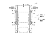
- FIG. 9 shows a conventional general seat slide device 81.
- the seat slide device 81 has a pair of rail units 82, 82 on both sides in the seat width direction.
- Each rail unit 82, 82 comprises a lower rail 83 attached to the floor in the vehicle and an upper rail 84 attached to the back of the seat 85.
- a plurality of rollers 86 are interposed between the lower rail 83 and the upper rail 84.
- the rollers 86 are double-supported type having a pair of wheels on both sides in the seat width direction, and are disposed at two locations in the rail longitudinal direction (vehicle longitudinal direction) of each rail unit 82. That is, regarding the rollers 86, a total of four wheels are provided in each of the rail units 82, 82, that is, a total of eight wheels in the entire seat 85.
- the seat slide device 81 of FIG. 9 requires a total of eight wheels as the roller 86, so the number of wheels is too large, and the sliding resistance when moving the sheet 85 is increased. There's a problem. However, simply reducing the number of wheels may lead to the problem of rattling the seat, so there is a need for development of technology that can achieve both reduction in the number of wheels on the roller and prevention of rattling of the seat.
- An object of the present invention is to provide a seat slide device capable of reducing the number of roller wheels and making it possible to prevent occurrence of rattling of a sheet.
- a plurality of rail units provided between a sheet and a sheet mounting surface, wherein each rail unit is attached to the sheet mounting surface.
- a plurality of rail units including a rail member and a second rail member attached to the seat, wherein the position of the seat can be adjusted by sliding the second rail member relative to the first rail member;
- a plurality of rollers disposed between the first rail member and the second rail member, and three rollers are provided for each of the rail units, and the first rail is provided by the three rollers
- a seat slide device is provided, wherein the member supports the second rail member at three points.
- the first rail member supports the second rail member at three points by three rollers. Therefore, even if a deviation occurs in the height direction between the first rail member and the second rail member, this deviation can be effectively absorbed by the three-point support of the roller. . Therefore, it is possible to reduce the number of wheels of the roller, and it is also possible to make the sheet less likely to rattle.
- the number of wheels of the roller can be reduced, and the rattling of the sheet can be made less likely to occur.
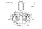
- FIG. 2 is a plan view showing the seat slide device of FIG. 1; The disassembled perspective view which shows a rail unit. Sectional drawing which shows the roller part of a rail unit. Sectional drawing which shows the shoe
- A) is a perspective view which shows one side of a shoe
- (b) is a perspective view which shows the other side of a shoe.
- (A) And (b) is a top view which shows the seat slide apparatus of another example. The top view of the seat slide apparatus of other another example. The top view which shows the conventional seat slide apparatus.
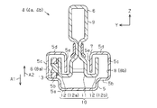
- the seat 1 installed in the vehicle is attached to the in-vehicle floor 3 via a seat slide device 2 that slides the seat 1 in the vehicle longitudinal direction (X-axis direction in FIG. 1). There is.
- the seat slide device 2 can set the position of the seat 1 in the vehicle longitudinal direction in multiple stages.
- the in-vehicle floor 3 corresponds to a seat attachment surface.
- the seat slide device 2 has a pair of elongated rail units 4, 4 on both sides in the sheet width direction (Y-axis direction in FIG. 2). Therefore, the seat 1 is supported on the floor 3 by the pair of rail units 4 arranged in the seat width direction.
- the pair of rail units 4 is a left side rail unit 4a located on the left side in the figure and a right side rail unit 4b located on the right side in the figure. Further, the left side rail unit 4 a and the right side rail unit 4 b are arranged to be symmetrical with respect to the center line in the width direction of the seat 1.
- the lower rail 5 attached to the in-vehicle floor 3 and the upper rail 6 attached to the back surface of the seat 1 are provided slidably.
- the lower rail 5 functions as a support rail for the upper rail 6 and thus is formed longer than the upper rail 6.
- the lower rail 5 and the upper rail 6 constitute a first rail member and a second rail member.
- grooves 7 are formed in a band along the longitudinal direction of the lower rail 5 (the X-axis direction in FIG. 3). Further, as shown in FIG. 4 and FIG. 5, a pair of space portions 8 communicating with the groove 7 is provided in the lower rail 5.
- the pair of spaces 8 is formed on both sides of the groove 7 in the sheet width direction (the Y-axis direction in FIGS. 4 and 5) with the groove 7 in the middle.
- the space portions 8 and 8 are indicated by 8a at the outer side in the sheet width direction, that is, on the left side in the drawing, and by 8b in the sheet width direction, that is, on the right side in the drawing.
- the lower rail 5 is formed by bending one steel material (iron plate).
- the upper rail 6 has a hollow main body portion 9 that abuts and supports the seat 1 and an extending portion 10 formed in a bifurcated shape from the main body portion 9 downward.
- the extending portion 10 includes a bifurcated portion 11 at the base of two stacked plate members and a pair of bent portions 12 and 12 bent upward from the tip of the bifurcated portion 11.
- the bent portions 12 have a substantially L-shaped cross section and are disposed symmetrically with respect to the center line of the upper rail 6 in the sheet width direction (the Y-axis direction in FIGS. 4 and 5).
- the pair of bent portions 12 and 12 is indicated by 12a located on the outer side in the sheet width direction, that is, on the left side of the sheet, and 12b in the sheet width direction, that is, located on the right side.
- the forked portion 11 is passed through the groove 7 of the lower rail 5, and the bent portions 12 a and 12 b are accommodated in the space portions 8 a and 8 b of the lower rail 5.
- Upper rail 6 slides relative to lower rail 5 along groove 7 along the longitudinal direction of the vehicle. The sliding position of the lower rail 5 and the upper rail 6, that is, the position of the seat 1 in the vehicle longitudinal direction is held by a lock mechanism (not shown) provided between the lower rail 5 and the upper rail 6.
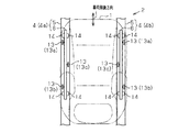
- rollers 13 for guiding the slide movement of the rails 5 and 6 are attached at a plurality of places.
- the rollers 13, 13... are rotatably supported on the side wall surfaces of the outer bent portion 12a and the inner bent portion 12b in each of the upper rails 6, 6 (only one is shown in FIG. 3).
- roller 13 in one upper rail 6, a roller structure in which the upper rail 6 is supported at three points with respect to the lower rail 5 is adopted.
- the roller structure is a cantilever type having wheels at only one of the pair of bent portions 12a and 12b at one roller arrangement position.
- one roller 13 is disposed at each end of the outer bent portion 12a in the longitudinal direction of the upper rail 6 (longitudinal direction of rail: X-axis direction in FIG. 3). It has a three-point support structure in which one roller 13 is disposed at the center in the longitudinal direction.
- the roller structure has a structure in which the upper rail 6 is supported at three points with respect to the lower rail 5 by the rollers 13 a and 13 b at both ends of the rail unit 4 and the roller 13 c in the middle. Further, in the rollers 13, cantilever wheels are alternately arranged along the rail longitudinal direction.
- the roller 13 has three wheels when viewed by the rail unit 4 on one side, and has a total of six wheels when viewed by the entire seat 1.
- the two rollers 13a, 13b are arranged outside the seat 1 with respect to the center line in the width direction of each rail unit 4a, 4b, and one roller 13c is for each rail unit 4a, 4b. It is arranged inside the sheet 1 with respect to the center line in the width direction.
- three rollers are arranged to form an apex of an isosceles triangle.
- the roller 13 is disposed on the upper surface of the roller rolling wall 5 b at a position one step higher than the bottom wall 5 a of the lower rail 5 in the space portion 8 of the lower rail 5. Then, when the upper rail 6 slides relative to the lower rail 5, the roller 13 rolls on the upper surface of the roller rolling wall 5 b to smoothly slide the upper rail 6, that is, the position of the seat 1 with a light force. Adjustment is ensured.
- a plurality of shoes 14 that suppress the rattling between the rails 5 and 6 are provided at a plurality of locations. It is attached.
- the shoes 14 are resin pieces for suppressing backlash.
- the shoes 14, 14... Are disposed in total at four rail longitudinal end portions of the outer bent portion 12a and the inner bent portion 12b in one rail unit 4. Therefore, a total of eight shoes 14 are arranged in each of the left side rail unit 4a and the right side rail unit 4b, four each when viewed in the entire seat 1.
- the shoe 14 corresponds to a rattling suppressing member.
- the shoe 14 has an outer sliding contact 15 for absorbing rattling in the sheet width direction (Y-axis direction in FIG. 5), and a vertical direction (Z in FIG. 5) of the rail unit 4. And an upper sliding contact piece 16 for absorbing rattling.
- the outer sliding contact piece 15 is formed by hollowing the side portion of the shoe 14 and is in sliding contact with the inner surface of the outer wall 5 c of the lower rail 5.
- the upper sliding contact piece 16 is formed by hollowing the entire upper portion of the shoe 14, and can slide on the inner surface of the upper wall 5 d of the lower rail 5.
- the upper sliding contact piece 16 and the outer sliding contact piece 15 are both formed in a substantially arc shape.
- the outer sliding contact piece 15 and the upper sliding contact piece 16 are attached to stepped portions 17 (recessed portions) formed to be recessed in the tip end surfaces of the respective bent portions 12a and 12b.
- the stepped portion 17 is at a position one step lower than the tip end surfaces of the bent portions 12a and 12b.
- the outer sliding contact piece 15 and the upper sliding contact piece 16 are positioned on the upper rail 6 by engaging the mounting groove 18 formed in the self with the stepped portion 17.
- the space portion 8 is formed by a region surrounded by the bottom wall 5a, the roller rolling wall 5b, the outer wall 5c, the upper wall 5d, and the inner wall 5e.
- channel 7 says the area
- one of the wheels in the roller 13 may be multiplied by the mounting height, and the upper rail 6 may be inclined relative to the lower rail 5 in the direction of arrow A1 in FIG. Ru.
- an excessive load is applied to a specific one wheel, and the lower rail 5 and the shoe 14 are in a strong interference state, which may increase the sliding resistance when moving the seat 1. That is, when adjusting the position of the sheet 1, the operator feels the sheet 1 heavy, which makes it difficult to perform the position alignment.
- positioned at each rail unit 4a, 4b is set to three (13a, 13b, 13c).
- the seat slide device 2 has a structure in which the upper rail 6 is supported at three points with respect to the lower rail 5 by these three wheels. Therefore, the upper rail 6 can be supported on the lower rail 5 in one plane by the three-point support structure.
- the seat slide device 2 it is only necessary to provide three rollers 13 for each of the rail units 4a and 4b. That is, when viewed in the entire sheet 1, only six rollers 13 may be provided. Therefore, it is possible to suppress rattling of the seat 1 while suppressing the number of wheels mounted on the seat slide device 2 to a small number.
- each of the rail units 4a and 4b has a three-point support structure with three rollers 13, between the lower rail 5 and the upper rail 6 in units of each rail unit 4a and 4b.
- the rattling is suppressed. For this reason, the effect of securing stable slide movement of the seat 1 is enhanced. Note that rattling between the left and right rail units 4 a and 4 b is absorbed by the frame of the seat 1.
- the support of the upper rail 6 with respect to the lower rail 5 is performed by three-point support by the three cantilever rollers 13a, 13b and 13c. Therefore, even if a deviation occurs in the rail height direction between the rails 5 and 6, this deviation can be absorbed by the three-point support of the roller 13. Therefore, the number of wheels of the roller 13 can be reduced, and the looseness of the seat 1 can be reduced.
- warping deformation refers to a deformation in which the center of the lower rail 5 is lowered and the both ends are lifted.
- the shoe 14 is disposed between the two rollers 13 as in the present embodiment, the shoe 14 is effective to fill the gap caused by the rail deformation, which is effective in suppressing the rattling of the sheet 1 Becomes higher.
- the embodiment is not limited to the configuration described above, and may be changed to the following modes.
- the rollers 13a and 13b located at the end of the upper rail 6 may be disposed in the inner bent portion 12b, and the middle roller 13c may be disposed in the outer bent portion 12a.
- the two rollers 13 located at the end of the upper rail 6 are disposed inside the sheet 1 with respect to the center line in the width direction of the rail units 4a, 4b. Are disposed on the outside of the seat 1 with respect to the center line in the width direction of the rail units 4a and 4b.
- the roller 13 may be arrange
- the two rollers 13a, 13b located at the end of the upper rail 6 are arranged outside the seat 1 with respect to the center line in the width direction of each rail unit 4a, 4b.
- the two rollers 13c may be disposed inside the seat 1 with respect to the center line in the width direction of each of the rail units 4a and 4b.
- the shoe 14 is not limited to being disposed between the roller 13a (13b) located at the end of the upper rail 6 and the roller 13c in the middle. As shown in FIG. 8, the shoes 14 may be disposed outside the rollers 13 a and 13 b located at the end of the upper rail 6. That is, the shoe 14 on the front side is positioned forward of the roller 13a located on the vehicle frontmost side in the longitudinal direction of each rail unit 4a, 4b, and the shoe 14 on the rear side is in the longitudinal direction of each rail unit 4a, 4b. You may arrange
- the lower rail 5 may be attached to the seat 1 and the upper rail 6 may be attached to the in-vehicle floor 3.
- the number of rail units 4 is not limited to two, and may be, for example, three or more.
- the seat attachment surface is not limited to the in-vehicle floor 3 and may be changed to another place.
- the number of attached shoes 14 is not limited to eight in total, and can be changed as appropriate. Also, the mounting position of the shoe 14 may be changed as appropriate according to the use situation.
- the rattle suppressing member is not limited to the shoe 14, and other parts may be used.
- the arrangement position of the roller 13 is not limited to the example described in the embodiment or the other example, and can be changed to another arrangement position as long as it has a three-point support structure that can be supported on one plane.
- the seat slide device 2 is not limited to being applied to a vehicle, and can be applied to other devices and devices.
Landscapes
- Engineering & Computer Science (AREA)
- Aviation & Aerospace Engineering (AREA)
- Transportation (AREA)
- Mechanical Engineering (AREA)
- Seats For Vehicles (AREA)
Abstract
La présente invention porte sur un dispositif de coulissement de siège, lequel dispositif permet à un siège de véhicule d'être positionné dans la direction avant-arrière du véhicule. Ce dispositif de coulissement de siège comprend une paire d'unités de rail alignées dans la direction de la largeur du siège. Chacune des unités de rail comprend un premier élément de rail qui est attaché à une surface de montage de siège et un second élément de rail qui est attaché au siège. Chaque unité de rail comporte trois rouleaux, et, à l'aide de ces trois rouleaux, le second élément de rail est supporté sur le premier élément de rail en trois points.
Priority Applications (3)
| Application Number | Priority Date | Filing Date | Title |
|---|---|---|---|
| US14/123,689 US20140110554A1 (en) | 2011-06-07 | 2012-06-04 | Seat sliding device |
| EP12797435.0A EP2719574B1 (fr) | 2011-06-07 | 2012-06-04 | Dispositif de coulissement de siège |
| CN201290000578.1U CN203819069U (zh) | 2011-06-07 | 2012-06-04 | 座椅滑动装置 |
Applications Claiming Priority (2)
| Application Number | Priority Date | Filing Date | Title |
|---|---|---|---|
| JP2011-127616 | 2011-06-07 | ||
| JP2011127616A JP5441186B2 (ja) | 2011-06-07 | 2011-06-07 | シートスライド装置 |
Publications (1)
| Publication Number | Publication Date |
|---|---|
| WO2012169455A1 true WO2012169455A1 (fr) | 2012-12-13 |
Family
ID=47296018
Family Applications (1)
| Application Number | Title | Priority Date | Filing Date |
|---|---|---|---|
| PCT/JP2012/064358 Ceased WO2012169455A1 (fr) | 2011-06-07 | 2012-06-04 | Dispositif de coulissement de siège |
Country Status (5)
| Country | Link |
|---|---|
| US (1) | US20140110554A1 (fr) |
| EP (1) | EP2719574B1 (fr) |
| JP (1) | JP5441186B2 (fr) |
| CN (1) | CN203819069U (fr) |
| WO (1) | WO2012169455A1 (fr) |
Families Citing this family (31)
| Publication number | Priority date | Publication date | Assignee | Title |
|---|---|---|---|---|
| JP2013023039A (ja) * | 2011-07-19 | 2013-02-04 | Aisin Seiki Co Ltd | シートスライド装置 |
| JP6284715B2 (ja) * | 2013-06-20 | 2018-02-28 | トヨタ紡織株式会社 | 乗物用シート |
| JP6324786B2 (ja) * | 2014-03-27 | 2018-05-16 | 株式会社今仙電機製作所 | シートレール装置 |
| FR3028812B1 (fr) * | 2014-11-26 | 2016-12-23 | Faurecia Sieges Automobile | Systeme comprenant une glissiere de siege de vehicule automobile et un support destine a y etre fixe |
| US10160350B2 (en) | 2015-06-30 | 2018-12-25 | Brose Fahrzeugteile Gmbh & Co. Kg, Coburg | Adjusting device for longitudinal adjustment of a vehicle seat and method for assembly |
| JP6589574B2 (ja) * | 2015-11-06 | 2019-10-16 | アイシン精機株式会社 | 車両用のシートスライド装置 |
| DE102016224663B4 (de) | 2015-12-15 | 2019-11-21 | Lear Corporation | Schienenanordnung |
| DE102016224588B4 (de) * | 2015-12-15 | 2023-09-21 | Lear Corporation | Schienenbaugruppe |
| US10717373B2 (en) | 2016-06-27 | 2020-07-21 | Toyota Body Seiko Co., Ltd. | Seat slide device |
| DE102016225818B4 (de) * | 2016-09-21 | 2021-05-12 | Adient Luxembourg Holding S.À R.L. | Längseinsteller sowie Fahrzeugsitz |
| JP6717145B2 (ja) * | 2016-09-28 | 2020-07-01 | トヨタ紡織株式会社 | シート用スライド装置 |
| CN107953804B (zh) * | 2016-10-14 | 2021-04-09 | 丰田车体精工株式会社 | 座椅滑动装置 |
| JP6676006B2 (ja) * | 2016-10-14 | 2020-04-08 | トヨタ車体精工株式会社 | シートスライド装置 |
| CN108327583B (zh) * | 2018-01-25 | 2019-10-11 | 延锋安道拓座椅有限公司 | 一种具有间隙消除结构的汽车座椅地滑轨 |
| US11506272B2 (en) | 2020-02-21 | 2022-11-22 | Lear Corporation | Track system with a support member |
| JP7219639B2 (ja) * | 2019-03-04 | 2023-02-08 | トヨタ車体精工株式会社 | シートスライド装置 |
| FR3091212B1 (fr) * | 2019-01-02 | 2022-07-29 | Faurecia Sieges Dautomobile | Glissière pour siège de véhicule et siège de véhicule comportant une telle glissière |
| JP7247602B2 (ja) * | 2019-01-25 | 2023-03-29 | トヨタ紡織株式会社 | スライド装置 |
| US11807142B2 (en) | 2019-03-06 | 2023-11-07 | Lear Corporation | Electrical track assembly |
| CN110076632A (zh) * | 2019-04-26 | 2019-08-02 | 深圳市圆梦精密技术研究院 | 工件检测装置 |
| US11463083B2 (en) | 2019-10-04 | 2022-10-04 | Lear Corporation | Electrical system |
| US11634101B2 (en) | 2019-10-04 | 2023-04-25 | Lear Corporation | Removable component system |
| US11323114B2 (en) | 2019-10-04 | 2022-05-03 | Lear Corporation | Electrical system |
| DE102021104018B4 (de) | 2020-02-21 | 2023-11-09 | Lear Corporation | Schienensystem mit einem Stützelement, Verfahren zum Betreiben eines Schienensystems |
| US11505141B2 (en) | 2020-10-23 | 2022-11-22 | Lear Corporation | Electrical system with track assembly and support assembly |
| US11362217B1 (en) | 2020-11-23 | 2022-06-14 | Taiwan Semiconductor Manufacturing Company, Ltd. | Method of forming transistors of different configurations |
| JP2022124085A (ja) * | 2021-02-15 | 2022-08-25 | トヨタ車体精工株式会社 | シートスライド装置 |
| JP2022131837A (ja) * | 2021-02-26 | 2022-09-07 | トヨタ車体精工株式会社 | シートスライド装置 |
| US11904735B2 (en) * | 2021-04-22 | 2024-02-20 | Ford Global Technologies, Llc | Translation assembly for a vehicle |
| JP2023164000A (ja) * | 2022-04-28 | 2023-11-10 | アディエント ユーエス エルエルシー | シートスライド装置 |
| KR102747834B1 (ko) * | 2022-10-12 | 2024-12-31 | 주식회사 다스 | 차량용 시트 슬라이딩 장치 |
Citations (5)
| Publication number | Priority date | Publication date | Assignee | Title |
|---|---|---|---|---|
| JPH01176536U (fr) * | 1988-06-02 | 1989-12-15 | ||
| JPH07197404A (ja) | 1993-12-28 | 1995-08-01 | Ishikawajima Harima Heavy Ind Co Ltd | レール締結ロボットにおける走行台車 |
| JP2000343988A (ja) * | 1999-06-03 | 2000-12-12 | Nissan Motor Co Ltd | 車両用シート |
| JP2001213310A (ja) | 2000-02-01 | 2001-08-07 | Daifuku Co Ltd | 荷搬送設備 |
| JP2003146119A (ja) * | 2001-11-12 | 2003-05-21 | Aisin Seiki Co Ltd | シートスライド装置 |
Family Cites Families (5)
| Publication number | Priority date | Publication date | Assignee | Title |
|---|---|---|---|---|
| US4184656A (en) * | 1978-01-03 | 1980-01-22 | The Boeing Company | Seat track mechanism for operating station of aircraft refueling boom |
| US5036953A (en) * | 1989-10-12 | 1991-08-06 | Munz William E | Retractable elevator door |
| US5711227A (en) * | 1996-01-16 | 1998-01-27 | Johnson; Jerome K. | Portable and collapsible dolly and track |
| US6059345A (en) * | 1998-06-18 | 2000-05-09 | Tachi-S Co., Ltd. | Slide rail device for vehicle seat |
| FR2902454A1 (fr) * | 2006-06-16 | 2007-12-21 | Snecma Sa | Stator de turbomachine comportant un etage d'aubes de redresseurs actionnees par une couronne rotative a centrage automatique |
-
2011
- 2011-06-07 JP JP2011127616A patent/JP5441186B2/ja active Active
-
2012
- 2012-06-04 CN CN201290000578.1U patent/CN203819069U/zh not_active Expired - Lifetime
- 2012-06-04 US US14/123,689 patent/US20140110554A1/en not_active Abandoned
- 2012-06-04 EP EP12797435.0A patent/EP2719574B1/fr active Active
- 2012-06-04 WO PCT/JP2012/064358 patent/WO2012169455A1/fr not_active Ceased
Patent Citations (5)
| Publication number | Priority date | Publication date | Assignee | Title |
|---|---|---|---|---|
| JPH01176536U (fr) * | 1988-06-02 | 1989-12-15 | ||
| JPH07197404A (ja) | 1993-12-28 | 1995-08-01 | Ishikawajima Harima Heavy Ind Co Ltd | レール締結ロボットにおける走行台車 |
| JP2000343988A (ja) * | 1999-06-03 | 2000-12-12 | Nissan Motor Co Ltd | 車両用シート |
| JP2001213310A (ja) | 2000-02-01 | 2001-08-07 | Daifuku Co Ltd | 荷搬送設備 |
| JP2003146119A (ja) * | 2001-11-12 | 2003-05-21 | Aisin Seiki Co Ltd | シートスライド装置 |
Non-Patent Citations (1)
| Title |
|---|
| See also references of EP2719574A4 |
Also Published As
| Publication number | Publication date |
|---|---|
| US20140110554A1 (en) | 2014-04-24 |
| JP2012254669A (ja) | 2012-12-27 |
| EP2719574A1 (fr) | 2014-04-16 |
| EP2719574A4 (fr) | 2014-07-16 |
| JP5441186B2 (ja) | 2014-03-12 |
| CN203819069U (zh) | 2014-09-10 |
| EP2719574B1 (fr) | 2015-10-28 |
Similar Documents
| Publication | Publication Date | Title |
|---|---|---|
| WO2012169455A1 (fr) | Dispositif de coulissement de siège | |
| JP2013023039A (ja) | シートスライド装置 | |
| US8757578B2 (en) | Slide device for vehicle seat | |
| TWI607722B (zh) | 滑軌總成 | |
| JP3678191B2 (ja) | シートスライド装置 | |
| JP5400422B2 (ja) | プラットホーム用ステップ装置 | |
| JP4791553B2 (ja) | 自動車の座席のための膨らんだスライダ | |
| JP2012254669A5 (fr) | ||
| JP7345294B2 (ja) | 客室内における座席配列の変更構造 | |
| EP2292462B1 (fr) | Structure coulissante de siège de véhicule | |
| JPS6268145A (ja) | 車輌用シ−トスライドアジヤスタ− | |
| JP2020032736A (ja) | シートスライド装置 | |
| JP5365202B2 (ja) | 乗物シートのシートバック用サイドフレーム部材 | |
| JP2018052296A (ja) | 貨物自動車 | |
| JP5428227B2 (ja) | 車両用シート | |
| TWI730922B (zh) | 滑軌總成 | |
| KR102672939B1 (ko) | 이동식 레일장치 | |
| JP4259242B2 (ja) | シートスライド装置 | |
| JP2020044907A (ja) | シートレール装置 | |
| JP4208479B2 (ja) | エレベータのガイド装置 | |
| CN114449828B (zh) | 滑轨总成 | |
| JP5929592B2 (ja) | 車両用シート | |
| JP3370587B2 (ja) | リーチマスト装置 | |
| JP7202240B2 (ja) | 車両前部構造 | |
| CN118700944A (zh) | 汽车座椅下储物结构 |
Legal Events
| Date | Code | Title | Description |
|---|---|---|---|
| WWE | Wipo information: entry into national phase |
Ref document number: 201290000578.1 Country of ref document: CN |
|
| 121 | Ep: the epo has been informed by wipo that ep was designated in this application |
Ref document number: 12797435 Country of ref document: EP Kind code of ref document: A1 |
|
| WWE | Wipo information: entry into national phase |
Ref document number: 14123689 Country of ref document: US |
|
| WWE | Wipo information: entry into national phase |
Ref document number: 2012797435 Country of ref document: EP |
|
| NENP | Non-entry into the national phase |
Ref country code: DE |