WO2012172611A1 - Dispositif de conditionnement d'air - Google Patents
Dispositif de conditionnement d'air Download PDFInfo
- Publication number
- WO2012172611A1 WO2012172611A1 PCT/JP2011/003442 JP2011003442W WO2012172611A1 WO 2012172611 A1 WO2012172611 A1 WO 2012172611A1 JP 2011003442 W JP2011003442 W JP 2011003442W WO 2012172611 A1 WO2012172611 A1 WO 2012172611A1
- Authority
- WO
- WIPO (PCT)
- Prior art keywords
- refrigerant
- heat medium
- heat
- heat exchanger
- temperature
- Prior art date
- Legal status (The legal status is an assumption and is not a legal conclusion. Google has not performed a legal analysis and makes no representation as to the accuracy of the status listed.)
- Ceased
Links
Images







Classifications
-
- F—MECHANICAL ENGINEERING; LIGHTING; HEATING; WEAPONS; BLASTING
- F25—REFRIGERATION OR COOLING; COMBINED HEATING AND REFRIGERATION SYSTEMS; HEAT PUMP SYSTEMS; MANUFACTURE OR STORAGE OF ICE; LIQUEFACTION SOLIDIFICATION OF GASES
- F25B—REFRIGERATION MACHINES, PLANTS OR SYSTEMS; COMBINED HEATING AND REFRIGERATION SYSTEMS; HEAT PUMP SYSTEMS
- F25B49/00—Arrangement or mounting of control or safety devices
- F25B49/02—Arrangement or mounting of control or safety devices for compression type machines, plants or systems
-
- F—MECHANICAL ENGINEERING; LIGHTING; HEATING; WEAPONS; BLASTING
- F25—REFRIGERATION OR COOLING; COMBINED HEATING AND REFRIGERATION SYSTEMS; HEAT PUMP SYSTEMS; MANUFACTURE OR STORAGE OF ICE; LIQUEFACTION SOLIDIFICATION OF GASES
- F25B—REFRIGERATION MACHINES, PLANTS OR SYSTEMS; COMBINED HEATING AND REFRIGERATION SYSTEMS; HEAT PUMP SYSTEMS
- F25B9/00—Compression machines, plants or systems, in which the refrigerant is air or other gas of low boiling point
- F25B9/002—Compression machines, plants or systems, in which the refrigerant is air or other gas of low boiling point characterised by the refrigerant
- F25B9/006—Compression machines, plants or systems, in which the refrigerant is air or other gas of low boiling point characterised by the refrigerant the refrigerant containing more than one component
-
- F—MECHANICAL ENGINEERING; LIGHTING; HEATING; WEAPONS; BLASTING
- F25—REFRIGERATION OR COOLING; COMBINED HEATING AND REFRIGERATION SYSTEMS; HEAT PUMP SYSTEMS; MANUFACTURE OR STORAGE OF ICE; LIQUEFACTION SOLIDIFICATION OF GASES
- F25B—REFRIGERATION MACHINES, PLANTS OR SYSTEMS; COMBINED HEATING AND REFRIGERATION SYSTEMS; HEAT PUMP SYSTEMS
- F25B13/00—Compression machines, plants or systems, with reversible cycle
-
- F—MECHANICAL ENGINEERING; LIGHTING; HEATING; WEAPONS; BLASTING
- F25—REFRIGERATION OR COOLING; COMBINED HEATING AND REFRIGERATION SYSTEMS; HEAT PUMP SYSTEMS; MANUFACTURE OR STORAGE OF ICE; LIQUEFACTION SOLIDIFICATION OF GASES
- F25B—REFRIGERATION MACHINES, PLANTS OR SYSTEMS; COMBINED HEATING AND REFRIGERATION SYSTEMS; HEAT PUMP SYSTEMS
- F25B2313/00—Compression machines, plants or systems with reversible cycle not otherwise provided for
- F25B2313/023—Compression machines, plants or systems with reversible cycle not otherwise provided for using multiple indoor units
- F25B2313/0231—Compression machines, plants or systems with reversible cycle not otherwise provided for using multiple indoor units with simultaneous cooling and heating
-
- F—MECHANICAL ENGINEERING; LIGHTING; HEATING; WEAPONS; BLASTING
- F25—REFRIGERATION OR COOLING; COMBINED HEATING AND REFRIGERATION SYSTEMS; HEAT PUMP SYSTEMS; MANUFACTURE OR STORAGE OF ICE; LIQUEFACTION SOLIDIFICATION OF GASES
- F25B—REFRIGERATION MACHINES, PLANTS OR SYSTEMS; COMBINED HEATING AND REFRIGERATION SYSTEMS; HEAT PUMP SYSTEMS
- F25B2400/00—Component parts or details not otherwise provided for in this subclass
- F25B2400/12—Inflammable refrigerants
-
- F—MECHANICAL ENGINEERING; LIGHTING; HEATING; WEAPONS; BLASTING
- F25—REFRIGERATION OR COOLING; COMBINED HEATING AND REFRIGERATION SYSTEMS; HEAT PUMP SYSTEMS; MANUFACTURE OR STORAGE OF ICE; LIQUEFACTION SOLIDIFICATION OF GASES
- F25B—REFRIGERATION MACHINES, PLANTS OR SYSTEMS; COMBINED HEATING AND REFRIGERATION SYSTEMS; HEAT PUMP SYSTEMS
- F25B2400/00—Component parts or details not otherwise provided for in this subclass
- F25B2400/12—Inflammable refrigerants
- F25B2400/121—Inflammable refrigerants using R1234
-
- F—MECHANICAL ENGINEERING; LIGHTING; HEATING; WEAPONS; BLASTING
- F25—REFRIGERATION OR COOLING; COMBINED HEATING AND REFRIGERATION SYSTEMS; HEAT PUMP SYSTEMS; MANUFACTURE OR STORAGE OF ICE; LIQUEFACTION SOLIDIFICATION OF GASES
- F25B—REFRIGERATION MACHINES, PLANTS OR SYSTEMS; COMBINED HEATING AND REFRIGERATION SYSTEMS; HEAT PUMP SYSTEMS
- F25B2500/00—Problems to be solved
- F25B2500/19—Calculation of parameters
-
- F—MECHANICAL ENGINEERING; LIGHTING; HEATING; WEAPONS; BLASTING
- F25—REFRIGERATION OR COOLING; COMBINED HEATING AND REFRIGERATION SYSTEMS; HEAT PUMP SYSTEMS; MANUFACTURE OR STORAGE OF ICE; LIQUEFACTION SOLIDIFICATION OF GASES
- F25B—REFRIGERATION MACHINES, PLANTS OR SYSTEMS; COMBINED HEATING AND REFRIGERATION SYSTEMS; HEAT PUMP SYSTEMS
- F25B2600/00—Control issues
- F25B2600/21—Refrigerant outlet evaporator temperature
-
- F—MECHANICAL ENGINEERING; LIGHTING; HEATING; WEAPONS; BLASTING
- F25—REFRIGERATION OR COOLING; COMBINED HEATING AND REFRIGERATION SYSTEMS; HEAT PUMP SYSTEMS; MANUFACTURE OR STORAGE OF ICE; LIQUEFACTION SOLIDIFICATION OF GASES
- F25B—REFRIGERATION MACHINES, PLANTS OR SYSTEMS; COMBINED HEATING AND REFRIGERATION SYSTEMS; HEAT PUMP SYSTEMS
- F25B2700/00—Sensing or detecting of parameters; Sensors therefor
- F25B2700/19—Pressures
- F25B2700/193—Pressures of the compressor
- F25B2700/1933—Suction pressures
-
- F—MECHANICAL ENGINEERING; LIGHTING; HEATING; WEAPONS; BLASTING
- F25—REFRIGERATION OR COOLING; COMBINED HEATING AND REFRIGERATION SYSTEMS; HEAT PUMP SYSTEMS; MANUFACTURE OR STORAGE OF ICE; LIQUEFACTION SOLIDIFICATION OF GASES
- F25B—REFRIGERATION MACHINES, PLANTS OR SYSTEMS; COMBINED HEATING AND REFRIGERATION SYSTEMS; HEAT PUMP SYSTEMS
- F25B2700/00—Sensing or detecting of parameters; Sensors therefor
- F25B2700/21—Temperatures
- F25B2700/2117—Temperatures of an evaporator
- F25B2700/21174—Temperatures of an evaporator of the refrigerant at the inlet of the evaporator
Definitions
- the present invention relates to an air conditioner applied to, for example, a building multi air conditioner.
- Some air conditioners include a heat source unit (outdoor unit) arranged outside a building and an indoor unit arranged inside a building, such as a building multi-air conditioner.
- the refrigerant circulating in the refrigerant circuit of such an air conditioner radiates heat (heat absorption) to the air supplied to the heat exchanger of the indoor unit, and heats or cools the air.
- the heated or cooled air is sent into the air-conditioning target space for heating or cooling.
- a building normally has a plurality of indoor spaces, and accordingly, the indoor unit also includes a plurality of indoor units.
- the refrigerant pipe connecting the outdoor unit and the indoor unit may be 100 m. When the length of the pipe connecting the outdoor unit and the indoor unit is long, the amount of refrigerant charged in the refrigerant circuit increases accordingly.
- Such indoor units of multi-air conditioners for buildings are usually arranged and used in indoor spaces where people are present (for example, office spaces, living rooms, stores, etc.). If for some reason the refrigerant leaks from the indoor unit placed in the indoor space, depending on the type of refrigerant, it may be flammable or toxic, which may be a problem from the perspective of human impact and safety There is. Moreover, even if it is a refrigerant
- the air conditioner is adopted as a secondary loop
- the primary loop is made of a refrigerant
- the non-hazardous water or brine is used for the secondary loop
- a space where people are present A method of air-conditioning is conceivable.
- GWP global warming potential
- R32, HFO1234yf, HFO1234ze, and the like are considered promising.
- R32 is used as a refrigerant, the physical properties are almost the same as those of R410A, which is currently most frequently used, so the design change from the current machine is small and the development load is small, but the GWP is slightly high at 675.
- the GWP can be reduced while increasing the pressure of the refrigerant.
- these mixed refrigerants are non-azeotropic mixed refrigerants. It is known that an air conditioner employing this non-azeotropic refrigerant mixture has a different refrigerant composition and a refrigerant composition that actually circulates in the refrigeration cycle. This is because the boiling points of the refrigerants to be mixed are different as described above.
- the technique described in Patent Document 1 has a bypass circuit connected so as to bypass the compressor, and a double pipe heat exchanger and a capillary tube are connected to the bypass circuit. And a refrigerant composition is computed based on the detection result of the various detection means installed in this bypass circuit, and the refrigerant composition set up temporarily.
- the technique described in Patent Document 1 repeatedly calculates until the calculated refrigerant composition satisfies the control flow condition, and calculates the refrigerant composition.
- the technique described in Patent Document 2 is a technique for temporarily setting the refrigerant composition and calculating the refrigerant composition by repetitive calculation. Furthermore, it has a calculation flow for omitting repeated calculations.
- JP-A-8-75280 (see, for example, FIG. 8) Japanese Patent Laid-Open No. 11-63747 (see, for example, FIGS. 5 and 9)
- Patent Document 2 has a calculation flow for omitting repeated calculations. However, in this calculation flow, the accuracy of detecting the refrigerant composition may be reduced by omitting the calculation.
- An object of the air conditioning apparatus is to provide an air conditioning apparatus that calculates a refrigerant composition with high accuracy while reducing a calculation load of a control device (arithmetic unit) and a load on a ROM.
- An air conditioner includes a compressor, a first heat exchanger, a throttle device, and a second heat exchanger, which are connected by a refrigerant pipe to constitute a refrigeration cycle, and the refrigerant of the refrigerant cycle
- an air conditioner employing a non-azeotropic refrigerant as a bypass circuit, a bypass circuit connected to bypass the compressor, and a bypass heat exchange provided in the bypass circuit to cool the refrigerant flowing from the compressor into the bypass circuit
- a second expansion device that is provided in the bypass circuit and depressurizes the refrigerant flowing out of the bypass heat exchanger, the temperature of the refrigerant flowing into the second expansion device, and the temperature of the refrigerant flowing out of the second expansion device
- refrigerant state detection means for detecting the pressure of the refrigerant sucked into the compressor, and an arithmetic device for calculating the composition of the refrigerant circulating in the refrigeration cycle based on the detection result of the refrigerant state detection means,
- the arithmetic unit applies the inlet liquid enthalpy calculated based on the temperature of the refrigerant flowing into the second throttling device, the temperature of the refrigerant flowing out from the second throttling device, or the compressor. Based on the saturated gas enthalpy and saturated liquid enthalpy calculated based on the pressure of the sucked refrigerant, the dryness of the refrigerant flowing out from the second expansion device is calculated, and the refrigerant flowing out from the second expansion device is calculated.
- the liquid phase concentration and the gas phase concentration of the refrigerant flowing out from the second throttling device are calculated, and the calculated dryness, liquid phase concentration, and gas phase are calculated.
- the composition of the refrigerant circulating in the refrigeration cycle is calculated.
- FIG. 4 is a diagram in which points A to D shown in the bypass circuit shown in FIG. 3 are made to correspond to each other on a PH diagram. It is a flowchart explaining the control flow for calculating the refrigerant composition employ
- (A) shows the correlation between the saturated liquid temperature and the liquid refrigerant concentration, and the correlation between the saturated gas temperature of the refrigerant and the gas refrigerant concentration
- (b) shows the correlation between the dryness and the refrigerant composition.
- the bypass circuit shown in FIG. 3 is provided with an opening / closing device. It is a refrigerant circuit figure which shows the flow of the refrigerant
- FIG. 1 is a schematic diagram illustrating an installation example of the air-conditioning apparatus 100 according to the present embodiment. Based on FIG. 1, the installation example of the air conditioning apparatus 100 is demonstrated.
- the air conditioner 100 has a refrigeration cycle for circulating refrigerant, and each of the indoor units 2a to 2d can freely select a cooling mode or a heating mode as an operation mode.
- the air conditioning apparatus 100 which concerns on this Embodiment is the refrigerant
- the refrigerant composition in the present embodiment refers to the composition of R32, which is a low boiling point refrigerant circulating in the refrigeration cycle, unless otherwise specified.
- the refrigerant composition of HFO1234yf which is a high boiling point refrigerant
- the air conditioner 100 employs a system (indirect system) that indirectly uses a refrigerant (heat source side refrigerant). That is, the cold or warm heat stored in the heat source side refrigerant is transmitted to a refrigerant (hereinafter referred to as a heat medium) different from the heat source side refrigerant, and the air-conditioning target space is cooled or heated with the cold heat or heat stored in the heat medium.
- a refrigerant heat source side refrigerant
- an air conditioner 100 includes a single outdoor unit 1 that is a heat source unit, a plurality of indoor units 2, an outdoor unit 1, and an indoor unit 2. And a heat medium relay unit 3 interposed therebetween.
- the heat medium relay unit 3 performs heat exchange between the heat source side refrigerant and the heat medium.
- the outdoor unit 1 and the heat medium relay unit 3 are connected by a refrigerant pipe 4 for circulating the heat source side refrigerant.
- the heat medium relay unit 3 and the indoor unit 2 are connected by a pipe (heat medium pipe) 5 for circulating the heat medium.
- the cold or warm heat generated by the outdoor unit 1 is delivered to the indoor unit 2 via the heat medium converter 3.
- the outdoor unit 1 is usually disposed in an outdoor space 6 that is a space (for example, a rooftop) outside a building 9 such as a building, and supplies cold or hot energy to the indoor unit 2 via the heat medium converter 3. It is.
- the indoor unit 2 is disposed at a position where cooling air or heating air can be supplied to the indoor space 7 which is a space (for example, a living room) inside the building 9, and is used for cooling the indoor space 7 serving as a space to be air-conditioned. Air or heating air is supplied.
- the heat medium relay unit 3 is installed at a position different from the outdoor space 6 and the indoor space 7 as a separate housing from the outdoor unit 1 and the indoor unit 2.
- the heat medium converter 3 is connected to the outdoor unit 1 and the indoor unit 2 via the refrigerant pipe 4 and the pipe 5, respectively, and transmits cold heat or hot heat supplied from the outdoor unit 1 to the indoor unit 2. is there.
- the outdoor unit 1 and the heat medium converter 3 are connected via two refrigerant pipes 4, and the heat medium converter 3. And the indoor units 2a to 2d are connected through two pipes 5.
- each unit (the outdoor unit 1, the indoor unit 2, and the heat medium converter 3) is connected by way of the refrigerant pipe 4 and the pipe 5, thereby performing the construction. Is easy.
- the heat medium converter 3 is inside the building 9 but is a space other than the indoor space 7 such as a ceiling (for example, a space such as a ceiling behind the building 9, hereinafter, It is illustrated by way of example as being installed in a space 8).
- the heat medium relay 3 may be installed in a common space where there is an elevator or the like.
- the indoor unit 2 is a ceiling cassette type is shown as an example, it is not limited to this.
- the air conditioner 100 can be of any type as long as it is capable of blowing heating air or cooling air directly into the indoor space 7 or by a duct, etc. Good.
- the outdoor unit 1 is installed in the outdoor space 6 as an example, but the present invention is not limited to this.
- the outdoor unit 1 may be installed in an enclosed space such as a machine room with a ventilation port, or the interior of the building 9 if the exhaust heat can be exhausted outside the building 9 by an exhaust duct. You may install in. Even when the water-cooled outdoor unit 1 is used, it may be installed inside the building 9. Even if the outdoor unit 1 is installed in such a place, no particular problem occurs.
- the heat medium converter 3 can also be installed in the vicinity of the outdoor unit 1. However, it should be noted that if the distance from the heat medium relay unit 3 to the indoor unit 2 is too long, the power for transporting the heat medium becomes considerably large, and the energy saving effect is diminished. Furthermore, the number of connected outdoor units 1, indoor units 2, and heat medium converters 3 is not limited to the number illustrated in FIG. 1. For example, the number of units can be set according to the building 9 in which the air conditioner 100 is installed. Just decide.
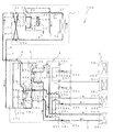
- FIG. 2 is a refrigerant circuit configuration example of the air-conditioning apparatus 100 according to the embodiment of the present invention.
- FIG. 3 is an enlarged view of the bypass circuit 50 (composition detection circuit) of the air-conditioning apparatus 100 shown in FIG.
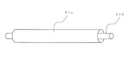
- FIG. 4 is a schematic view of the heat exchange device 51 shown in FIG.
- the configuration of the air conditioner 100 will be described in detail with reference to FIGS.
- the outdoor unit 1 and the heat medium relay unit 3 are connected to the refrigerant pipe 4 via the heat exchanger related to heat medium 15 a and the heat exchanger related to heat medium 15 b provided in the heat medium converter 3. Connected with.
- the heat medium relay unit 3 and the indoor unit 2 are also connected by the pipe 5 via the heat exchanger related to heat medium 15a and the heat exchanger related to heat medium 15b.
- the refrigerant pipe 4 will be described in detail later.
- the outdoor unit 1 stores a compressor 10 that compresses refrigerant, a first refrigerant flow switching device 11 that includes a four-way valve, a heat source side heat exchanger 12 that functions as an evaporator or a condenser, and excess refrigerant.
- An accumulator 19 is connected to and mounted on the refrigerant pipe 4.
- the outdoor unit 1 is also provided with a first connection pipe 4a, a second connection pipe 4b, a check valve 13a, a check valve 13b, a check valve 13c, and a check valve 13d.
- the heat medium is provided by providing the first connection pipe 4a, the second connection pipe 4b, the check valve 13a, the check valve 13b, the check valve 13c, and the check valve 13d.
- the flow of the heat source side refrigerant flowing into the converter 3 can be in a certain direction.
- the outdoor unit 1 has a bypass circuit 50 for detecting (calculating) the refrigerant composition.
- the bypass circuit 50 includes a heat exchange device 51 that exchanges heat between the refrigerant flowing from the discharge side of the compressor 10 and the refrigerant flowing into the suction side of the compressor 10, and a throttling device that depressurizes the refrigerant flowing into the bypass circuit 50. 52 is provided.
- the bypass circuit 50 includes an inlet temperature sensor 53 that detects the refrigerant temperature before flowing into the expansion device 52, an outlet temperature sensor 54 that detects the temperature of the refrigerant that has flowed out of the expansion device 52, and the refrigerant that has flowed out of the expansion device 53.
- An outlet pressure sensor 55 is provided for detecting the pressure. Further, as shown in FIG. 2, the outdoor unit 1 is provided with a calculation device 57 that calculates the refrigerant composition based on the detection results of the inlet temperature sensor 53, the outlet temperature sensor 54, and the outlet pressure sensor 55. ing.
- the compressor 10 sucks the heat source side refrigerant and compresses the heat source side refrigerant to a high temperature and high pressure state.
- the compressor 10 may be composed of an inverter compressor capable of capacity control.
- the first refrigerant flow switching device 11 has a flow of the heat source side refrigerant in the heating operation mode (in the heating only operation mode and the heating main operation mode) and in the cooling operation mode (in the all cooling operation mode and the cooling main operation mode). ) To switch the flow of the heat source side refrigerant.
- the heat source side heat exchanger 12 functions as an evaporator during heating operation, functions as a radiator (gas cooler) during cooling operation, and between the air supplied from a blower such as a fan (not shown) and the heat source side refrigerant. Heat exchange is performed.
- the accumulator 19 is provided on the suction side of the compressor 10, and surplus refrigerant due to a difference between the heating operation mode and the cooling operation mode, a change in the transient operation (for example, a change in the number of indoor units 2 operated). And excess refrigerant generated by load conditions. In this accumulator 19, it is separated into a liquid phase containing a large amount of high boiling point refrigerant and a gas phase containing a large amount of low boiling point refrigerant. Then, a liquid-phase refrigerant containing a large amount of high-boiling refrigerant is stored in the accumulator 19. For this reason, when the liquid phase refrigerant exists in the accumulator 19, the refrigerant composition circulating in the air conditioner 100 tends to increase in the low boiling point refrigerant.
- the heat exchange device 51 (bypass heat exchanger) exchanges heat between the refrigerant discharged from the compressor 10 and flowing into the bypass circuit 50 and the refrigerant flowing out of the expansion device 52 and decompressed. That is, the heat exchanging device 51 cools the high-pressure / high-temperature refrigerant discharged from the compressor 10 and flowing into the bypass circuit 50 to make a gas-liquid two-phase refrigerant.
- the heat exchange device 51 may employ, for example, a double pipe method. As shown in FIG. 4, the double-pipe system here refers to the low-pressure two-phase refrigerant flowing out of the expansion device 52 flowing in the inner pipe 51b, and the compressor 10 in the outer pipe (annular portion) 51a.
- the heat exchanging device 51 is not limited to this, and a configuration may be adopted in which the pipe 51a and the pipe 51b are brought into contact with each other, or a plate heat exchanger may be adopted although it is costly.
- the expansion device 52 decompresses the refrigerant that has flowed out of the heat exchange device 51 into a low-pressure gas-liquid two-phase refrigerant.
- the expansion device 52 has one end connected to the pipe 51 a of the heat exchange device 51 and the other end connected to the pipe 51 b of the heat exchange device 51.
- the expansion device 52 may be constituted by a device whose opening degree can be variably controlled, for example, an electronic expansion valve.
- the inlet temperature sensor 53 (which constitutes the refrigerant state detection means) detects the refrigerant temperature before flowing into the expansion device 52.
- the inlet temperature sensor 53 may be provided in a pipe connecting the pipe 51 a of the heat exchange device 51 and the expansion device 52.
- the outlet temperature sensor 54 (which constitutes the refrigerant state detection means) detects the temperature of the refrigerant that has flowed out of the expansion device 52.
- the outlet temperature sensor 54 may be provided in a pipe connecting the expansion device 52 and the pipe 51b of the heat exchange device 51.
- the inlet temperature sensor 53 and the outlet temperature sensor 54 are connected to an arithmetic device 57 that controls various devices.
- the outlet pressure sensor 55 (which constitutes the refrigerant state detection means) detects the pressure of the refrigerant that has flowed out of the expansion device 52.
- the outlet pressure sensor 55 is described as being provided, for example, in a pipe that connects the expansion device 52 and the pipe 51b of the heat exchange device 51, it is not limited thereto. That is, the outlet pressure sensor 55 may be provided in a pipe connecting the refrigerant outflow side of the expansion device 52 to the suction side of the compressor 10, or may be provided in a pipe downstream of the compressor 10. That is, the outlet pressure sensor 55 only needs to be provided at a position where the low-pressure refrigerant sucked into the compressor 10 can be detected.
- the piping on the downstream side of the compressor 10 corresponds to, for example, piping connecting the refrigerant flow switching device 11 and the accumulator 19.
- the outlet pressure sensor 55 is connected to an arithmetic unit 57 that controls various devices.
- the computing device 57 calculates the refrigerant composition based on the detection results of the inlet temperature sensor 53, the outlet temperature sensor 54, and the outlet pressure sensor 55.
- the computing device 57 is connected to an inlet temperature sensor 53, an outlet temperature sensor 54, and an outlet pressure sensor 55, and is also connected to a control device (not shown) that performs overall control of various devices described later. Accordingly, the control device can optimally control, for example, the opening degree of the expansion device 16 to be described later, based on the calculation result of the refrigerant composition of the arithmetic device 57.
- the calculation device 57 is illustrated as being installed in the outdoor unit 1 provided with the inlet temperature sensor 53, the outlet temperature sensor 54, and the outlet pressure sensor 55, but is not limited thereto. It may be installed in the indoor unit 2 or the heat medium relay unit 3.
- the computing device 57 has a physical property table indicating the correlation between the liquid enthalpy and the refrigerant temperature, the correlation between the saturated liquid enthalpy and the refrigerant temperature, and the correlation between the saturated gas enthalpy and the refrigerant temperature for each refrigerant composition value. , Stored in ROM. Further, the arithmetic device 57 stores, in the ROM, a physical property table indicating the correlation between the saturated liquid temperature and liquid refrigerant concentration of the refrigerant and the saturated gas temperature and gas refrigerant concentration of the refrigerant for each refrigerant pressure (FIG. 7). (See (a) and FIG. 7 (b)).
- the physical property table of the arithmetic device 57 can be set, for example, after the air conditioner 100 is installed. Moreover, although it has been described that the physical property table indicating the above-mentioned correlation is stored in the ROM in the arithmetic device 57, a formulated function may be stored instead of the table.
- the computing device 57 can calculate the liquid enthalpy (inlet liquid enthalpy) of the refrigerant flowing into the expansion device 53 based on the physical property table and the detection result of the inlet temperature sensor 53.
- the computing device 57 calculates the saturated liquid enthalpy and saturated gas enthalpy of the refrigerant flowing out from the expansion device 53 based on the physical property table and the detection result of the outlet temperature sensor 54, respectively.
- the calculation device 57 does not know the exact refrigerant composition value when calculating the inlet liquid enthalpy, saturated liquid enthalpy and saturated gas enthalpy, but sets the temporary refrigerant composition values to calculate these values. Is calculated. That is, the liquid enthalpy is calculated based on the physical property table corresponding to the set refrigerant composition value and the detection result of the inlet temperature sensor 53, and based on the physical property table and the detection result of the outlet temperature sensor 54. That is, the saturated liquid enthalpy and the saturated gas enthalpy are calculated. As described above, even if the accurate refrigerant composition value is not known, the air-conditioning apparatus 100 according to the present embodiment can calculate the refrigerant composition with high accuracy. It has become. This point will be described later.
- the arithmetic unit 57 determines the concentration of the liquid refrigerant flowing out from the expansion device 53 and the concentration of the gas refrigerant flowing out from the expansion device 53 based on the detection results of the physical property table, the outlet temperature sensor 54 and the outlet pressure sensor 55. Can be calculated.
- the computing device 57 can calculate the dryness based on the calculated inlet liquid enthalpy, saturated liquid enthalpy, and saturated gas enthalpy. The equation for calculating the dryness is calculated from Equation 1 shown below.
- the arithmetic device 57 calculates the refrigerant composition based on the dryness, the liquid refrigerant concentration, and the gas refrigerant concentration.
- the equation for calculating the refrigerant composition is calculated from Equation 2 shown below.
- Each indoor unit 2 is equipped with a use side heat exchanger 26.
- the use side heat exchanger 26 is connected to the heat medium flow control device 25 and the second heat medium flow switching device 23 of the heat medium converter 3 by the pipe 5.
- the use-side heat exchanger 26 performs heat exchange between air supplied from a blower such as a fan (not shown) and a heat medium, and generates heating air or cooling air to be supplied to the indoor space 7. To do.
- the heat medium converter 3 includes two heat medium heat exchangers 15 that exchange heat between the refrigerant and the heat medium, two expansion devices 16a and 16b that depressurize the refrigerant, and two that open and close the flow path of the refrigerant pipe 4. Opening / closing devices 17a and 17b, two second refrigerant flow switching devices 18 for switching the refrigerant flow channels, two pumps 21 for circulating the heat medium, and four first heat medium flow switching devices connected to one of the pipes 5 22, four second heat medium flow switching devices 23 connected to the other of the pipes 5 and four heat medium flow rates connected to the pipe 5 to which the second heat medium flow switching device 22 is connected An adjusting device 25 is provided.
- the two heat exchangers 15a and 15b function as condensers (heat radiators) or evaporators, and exchange heat between the heat source side refrigerant and the heat medium.
- the heat exchanger related to heat medium 15a is provided between the expansion device 16a and the second refrigerant flow switching device 18a in the refrigerant circuit A and serves to cool the heat medium in the cooling / heating mixed operation mode. is there.
- the heat exchanger related to heat medium 15b is provided between the expansion device 16b and the second refrigerant flow switching device 18b in the refrigerant circuit A and serves to heat the heat medium in the cooling / heating mixed operation mode. is there.
- the two expansion devices 16a and 16b (sometimes referred to as expansion devices 16) have a function as a pressure reducing valve or an expansion valve, and expand the heat source side refrigerant by reducing the pressure.
- the expansion device 16a is provided on the upstream side of the heat exchanger related to heat medium 15a in the flow of the heat source side refrigerant in the cooling only operation mode.
- the expansion device 16b is provided on the upstream side of the heat exchanger related to heat medium 15b in the flow of the heat source side refrigerant in the cooling only operation mode.
- the two expansion devices 16 may be configured by a device whose opening degree can be variably controlled, for example, an electronic expansion valve.
- the opening / closing devices 17a and 17b are configured by two-way valves or the like, and open and close the refrigerant pipe 4.
- the two second refrigerant flow switching devices 18a and 18b are composed of four-way valves or the like, and switch the flow of the heat source side refrigerant according to the operation mode. is there.
- the second refrigerant flow switching device 18a is provided on the downstream side of the heat exchanger related to heat medium 15a in the flow of the heat source side refrigerant in the cooling only operation mode.
- the second refrigerant flow switching device 18b is provided on the downstream side of the heat exchanger related to heat medium 15b in the flow of the heat source side refrigerant in the cooling only operation mode.
- the two pumps 21a and 21b (sometimes referred to as the pump 21) circulate the heat medium in the pipe 5.
- the pump 21 a is provided in the pipe 5 between the heat exchanger related to heat medium 15 a and the second heat medium flow switching device 23.
- the pump 21 b is provided in the pipe 5 between the heat exchanger related to heat medium 15 b and the second heat medium flow switching device 23.
- the two pumps 21 may be constituted by, for example, pumps capable of capacity control.
- the pump 21a may be provided in the pipe 5 between the heat exchanger related to heat medium 15a and the first heat medium flow switching device 22.
- the pump 21b may be provided in the pipe 5 between the heat exchanger related to heat medium 15b and the first heat medium flow switching device 22.
- the four first heat medium flow switching devices 22a to 22d are configured by three-way valves or the like, and switch the heat medium flow channels. .
- the first heat medium flow switching device 22 is provided in a number (here, four) according to the number of indoor units 2 installed. In the first heat medium flow switching device 22, one of the three sides is in the heat exchanger 15a, one of the three is in the heat exchanger 15b, and one of the three is in the heat medium flow rate. Each is connected to the adjusting device 25 and provided on the outlet side of the heat medium flow path of the use side heat exchanger 26.
- the four second heat medium flow switching devices 23a to 23d are composed of three-way valves or the like, and switch the heat medium flow channels. .
- the number of the second heat medium flow switching devices 23 is set according to the number of installed indoor units 2 (here, four).
- the heat exchanger is connected to the exchanger 26 and provided on the inlet side of the heat medium flow path of the use side heat exchanger 26.
- the second heat medium flow switching device 23a, the second heat medium flow switching device 23b, the second heat medium flow switching device 23c, and the second heat medium flow from the lower side of the drawing. This is illustrated as a switching device 23d.
- the four heat medium flow control devices 25a to 25d are composed of two-way valves or the like that can control the opening area, and adjust the flow rate of the heat medium flowing through the pipe 5. To do.
- the number of the heat medium flow control devices 25 is set according to the number of indoor units 2 installed (four in this case).
- One of the heat medium flow control devices 25 is connected to the use side heat exchanger 26 and the other is connected to the first heat medium flow switching device 22, and is connected to the outlet side of the heat medium flow channel of the use side heat exchanger 26. Is provided.
- the heat medium flow adjustment device 25 a, the heat medium flow adjustment device 25 b, the heat medium flow adjustment device 25 c, and the heat medium flow adjustment device 25 d are illustrated from the lower side of the drawing. Further, the heat medium flow control device 25 may be provided on the inlet side of the heat medium flow path of the use side heat exchanger 26.
- the heat medium relay 3 is provided with various detection means (two first temperature sensors 31a and 31b, four second temperature sensors 34a to 34d, four third temperature sensors 35a to 35d, and a pressure sensor 36). It has been. Information (for example, temperature information, pressure information, and heat source side refrigerant concentration information) detected by these detection means is sent to a control device that performs overall control of the operation of the air conditioner 100, and the drive frequency of the compressor 10, The number of rotations of a blower (not shown) provided near the heat source side heat exchanger 12 and the use side heat exchanger 26, switching of the first refrigerant flow switching device 11, driving frequency of the pump 21, and second refrigerant flow switching device 18 This is used for control such as switching of the heating medium and switching of the flow path of the heat medium.
- a blower not shown
- the control device (not shown) is configured by a microcomputer or the like, and calculates the evaporation temperature, the condensation temperature, the saturation temperature, the superheat degree, and the supercooling degree based on the calculation result of the refrigerant composition of the arithmetic device 57. Then, the control device, based on these calculation results, includes the opening degree of the expansion device 16, the rotational speed of the compressor 10, and the fan speed (including ON / OFF) of the heat source side heat exchanger 12 and the use side heat exchanger 26. ) And the like so that the performance of the air conditioner 100 is maximized.
- control device based on detection information from various detection means and instructions from the remote controller, the driving frequency of the compressor 10, the rotational speed of the blower (including ON / OFF), the first refrigerant flow switching device 11 Switching, driving of the pump 21, opening of the expansion device 16, opening and closing of the switching device 17, switching of the second refrigerant channel switching device 18, switching of the first heat medium channel switching device 22, switching of the second heat medium channel
- the switching of the device 23 and the opening degree of the heat medium flow control device 25 are controlled. That is, the control device performs overall control of various devices in order to execute each operation mode described later.
- the control device may be provided for each unit of the indoor unit 2 or may be provided in the heat medium relay unit 3. Further, although the control device is described as being separate from the arithmetic device 57, it may be the same.
- the two first temperature sensors 31 a and 31 b are the heat medium flowing out from the intermediate heat exchanger 15, that is, the heat medium at the outlet of the intermediate heat exchanger 15.
- the temperature is detected, and for example, a thermistor may be used.
- the first temperature sensor 31a is provided in the pipe 5 on the inlet side of the pump 21a.
- the first temperature sensor 31b is provided in the pipe 5 on the inlet side of the pump 21b.
- second temperature sensors 34a to 34d are provided between the first heat medium flow switching device 22 and the heat medium flow control device 25, and use side heat exchange.
- the temperature of the heat medium flowing out from the vessel 26 is detected, and it may be constituted by a thermistor.
- the number of the second temperature sensors 34 (four here) according to the number of indoor units 2 installed is provided. In correspondence with the indoor unit 2, the second temperature sensor 34a, the second temperature sensor 34b, the second temperature sensor 34c, and the second temperature sensor 34d are illustrated from the lower side of the drawing.
- third temperature sensors 35a to 35d are provided on the inlet side or the outlet side of the heat source side refrigerant of the heat exchanger related to heat medium 15, and are used as heat exchangers related to the heat medium.
- the temperature of the heat source side refrigerant flowing into the heat source 15 or the temperature of the heat source side refrigerant flowing out of the heat exchanger related to heat medium 15 is detected, and may be composed of a thermistor or the like.
- the third temperature sensor 35a is provided between the heat exchanger related to heat medium 15a and the second refrigerant flow switching device 18a.
- the third temperature sensor 35b is provided between the heat exchanger related to heat medium 15a and the expansion device 16a.
- the third temperature sensor 35c is provided between the heat exchanger related to heat medium 15b and the second refrigerant flow switching device 18b.
- the third temperature sensor 35d is provided between the heat exchanger related to heat medium 15b and the expansion device 16b.
- the pressure sensor 36 is provided between the heat exchanger related to heat medium 15b and the expansion device 16b, and between the heat exchanger related to heat medium 15b and the expansion device 16b. The pressure of the flowing heat source side refrigerant is detected.
- the piping 5 for circulating the heat medium is composed of one connected to the heat exchanger related to heat medium 15a and one connected to the heat exchanger related to heat medium 15b.
- the pipe 5 is branched (here, four branches each) according to the number of indoor units 2 connected to the heat medium relay unit 3.
- the pipe 5 is connected by a first heat medium flow switching device 22 and a second heat medium flow switching device 23.
- the first heat medium flow switching device 22 and the second heat medium flow switching device 23 By controlling the first heat medium flow switching device 22 and the second heat medium flow switching device 23, the heat medium from the heat exchanger related to heat medium 15a flows into the use-side heat exchanger 26, or the heat medium Whether the heat medium from the intermediate heat exchanger 15b flows into the use side heat exchanger 26 is determined.
- FIG. 5 is a diagram in which points A to D shown in the bypass circuit shown in FIG. 3 are made to correspond on the PH diagram. With reference to FIG. 5, the position in the PH diagram corresponding to each of the points A to D of the bypass circuit 50 will be described.
- the high-pressure liquid refrigerant (point B in FIG. 5) is exchanged and the enthalpy is reduced.
- This high-pressure liquid refrigerant is expanded by equal enthalpy in the expansion device 52 to a low-pressure gas-liquid two-phase state (point C in FIG. 5).
- This low-pressure gas-liquid two-phase refrigerant flows into the pipe 51b of the heat exchange device 51, exchanges heat with the high-pressure refrigerant, increases the enthalpy, becomes a low-pressure gas refrigerant (point D in FIG. 5), and from the accumulator 19 It merges with the refrigerant and is again sucked into the accumulator 19.
- FIG. 6 is a flowchart illustrating a control flow for calculating the refrigerant composition employed in the air-conditioning apparatus 100 according to the present embodiment.
- the control flow for the arithmetic unit 57 to calculate the refrigerant composition will be described.
- Step ST1 The arithmetic device 57 reads the detection result (TH1) of the inlet temperature sensor 53, the detection result (TH2) of the outlet temperature sensor 54, and the detection result (P1) of the outlet pressure sensor 55. Thereafter, the process proceeds to step ST2.
- Step ST2 The computing device 57 temporarily sets the composition value of the circulating refrigerant and outputs a physical property table corresponding to the set value. Then, the computing device 57 calculates the enthalpy Hin (inlet liquid enthalpy) of the refrigerant flowing into the expansion device 53 based on the detection result of the inlet temperature sensor 53 in step ST1 and this physical property table. Thereafter, the process proceeds to step ST3.
- the composition of the circulating refrigerant to be set is the composition ratio of the non-azeotropic mixed refrigerant filled in the air conditioner 100.
- a refrigerant composition having a high rate of occurrence may be examined in advance through experiments or the like, and the refrigerant composition may be adopted.
- Step ST3 The computing device 57 calculates the saturated liquid enthalpy Hls and the saturated gas enthalpy Hgs of the refrigerant flowing out from the expansion device 53 based on the detection result of the outlet temperature sensor 54 in step ST1 and the physical property table in step ST2. Thereafter, the process proceeds to step ST4.
- Step ST4 The computing device 57 calculates the dryness Xr based on the inlet liquid enthalpy Hin in step ST2, the saturated liquid enthalpy Hls and saturated gas enthalpy Hgs in step ST3, and Equation 1. Thereafter, the process proceeds to step ST5. Since the composition ratio of the filled non-azeotropic refrigerant mixture is adopted as the refrigerant composition as described in step ST2, the calculated dryness Xr is the dryness Xr in the filling composition.
- Step ST5 Based on the detection result of the outlet temperature sensor 54 in step ST1, the detection result of the outlet pressure sensor 55 in step ST1, and the physical property table, the arithmetic device 57 calculates the concentration XR32 of the liquid refrigerant flowing out from the expansion device 53, and the throttle The concentration YR32 of the gas refrigerant flowing out from the device 53 is calculated. Thereafter, the process proceeds to step 6.
- Step ST6 The computing device 57 calculates the refrigerant composition ⁇ based on the dryness Xr calculated in step ST4, the liquid refrigerant concentration XR32 and the gas refrigerant concentration YR32 calculated in step ST5, and Equation 2. Thereafter, the process proceeds to step ST7.
- Step ST7 The computing device 57 outputs the refrigerant composition ⁇ calculated in step ST6 to the control device.
- FIG. 7A is a diagram showing the correlation between the saturated liquid temperature and the liquid refrigerant concentration, and the correlation between the saturated gas temperature of the refrigerant and the gas refrigerant concentration
- FIG. 7B is a diagram showing the correlation between the dryness and the refrigerant composition. is there.
- FIG. 7 is also referred to as a concentration equilibrium diagram.
- F degree of freedom
- n number of mixed refrigerants
- r number of phases.
- the temperature and pressure of the refrigerant in the gas-liquid two-phase state flowing out from the expansion device 53 are detected by the outlet temperature sensor 54 and the outlet pressure sensor 55, respectively.
- the state of the refrigerating cycle in a gas-liquid two-phase state can be determined. That is, the concentration of the liquid phase in the low boiling point refrigerant and the concentration of the gas phase in the low boiling point refrigerant can be determined.
- the liquid phase concentration in the low-boiling refrigerant is surely determined. It can be seen that the gas phase concentration in the low boiling refrigerant is determined.
- the dryness calculated in step ST4 is applied to the graph of FIG. 7A, it corresponds to the dotted line of FIG. 7B. That is, when the liquid phase concentration XR32 (liquid side concentration) and the gas phase concentration YR32 (gas side concentration) illustrated in FIG. 7A are converted into the low boiling point refrigerant concentration (refrigerant composition) by this dryness. This is expressed as ⁇ in FIG.
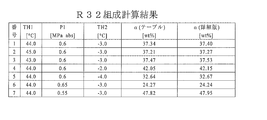
- FIG. 8 is a table for explaining how much error the refrigerant composition set in the control flow for calculating the refrigerant composition gives to the calculated refrigerant composition.
- FIG. 17 is a diagram showing the relationship between the dryness and the refrigerant composition of R32.
- ⁇ b in FIG. 8 is the refrigerant composition value set in step ST2. Then, the calculation result of the refrigerant composition when the set value ⁇ b is used is ⁇ .
- the detection result TH1 of the inlet temperature sensor 53 is 44 (° C.)
- the detection result TH2 of the outlet temperature sensor 54 is ⁇ 3 (° C.)
- the detection result P1 of the outlet pressure sensor 55 is 0.6 (MPa abs).
- the refrigerant composition was calculated.
- the air-conditioning apparatus 100 can calculate the refrigerant composition with high accuracy without setting the refrigerant composition as in the past and calculating the refrigerant composition by repeated calculation. .
- the calculation load concerning the arithmetic unit 57 and the load concerning ROM of the arithmetic unit 57 are reduced.
- the calculation load and the capacity load on the ROM can be reduced, it is not necessary to improve the calculation speed of the calculation device 57 or increase the capacity, so that an increase in the cost of the air conditioner 100 can be suppressed.
- the air conditioning apparatus 100 calculates the dryness Xr in step ST4, and calculates the liquid refrigerant concentration XR32 and the gas refrigerant concentration YR32 in step ST5.
- step ST7 the refrigerant composition is calculated from the calculated dryness Xr, liquid refrigerant concentration XR32, and gas refrigerant concentration YR32. That is, in order to predict the refrigerant composition, it can be said that the estimation method using the concentration balance diagram obtained from the detection result of the outlet temperature sensor 54 and the outlet pressure sensor 55 through the dryness is the best. Therefore, the air conditioning apparatus 100 according to the present embodiment can calculate the refrigerant composition with high accuracy by adopting this calculation method.
- FIG. 9 is a table for explaining how much error various detection results in the control flow for calculating the refrigerant composition give to the calculated refrigerant composition.
- the error which the detection result of the inlet temperature sensor 53 gives to the calculated refrigerant composition will be described in particular.
- two types of refrigerant composition detection results ⁇ are described. That is, ⁇ (table) and ⁇ (detailed version).
- ⁇ (table) is the result of calculating the refrigerant composition using the physical property table of the computing device 57.
- ⁇ (detailed version) is the result of calculating the refrigerant composition in detail by the analysis by REFPROP Version 8.0 without using the physical property table.
- the inlet temperature sensor 53 preferably has an accuracy of ⁇ 1 [° C.].
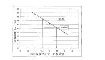
- FIG. 10 is a graph for explaining how much error the detection result of the outlet temperature sensor 54 gives to the calculated refrigerant composition.
- the detection accuracy of the outlet temperature sensor 54 is It turns out that it is good to set it as about ⁇ 0.5 (degreeC).
- FIG. 11 is a graph for explaining how much error the detection result of the outlet pressure sensor 55 gives to the calculated refrigerant composition.
- the detection accuracy of the outlet pressure sensor 55 is detected. It is understood that it is preferable to set the value to about ⁇ 0.01 (MPa).
- the arithmetic unit 57 can change the refrigerant composition. It can be calculated with high accuracy.
- the control device can calculate the evaporation temperature, the condensation temperature, the saturation temperature, the superheat degree, and the supercooling degree with high accuracy. Therefore, the opening degree of the expansion device 16, the rotational speed of the compressor 10, The fan speed (including ON / OFF) of the heat source side heat exchanger 12 and the use side heat exchanger 26 can be optimally controlled.
- FIG. 12 shows an example in which an opening / closing device 56 is provided in the bypass circuit 50 shown in FIG.
- the opening / closing device 56 is closed during non-stationary operation (for example, defrosting operation, operation mode switching, activation, etc.), and refrigerant is supplied to the bypass circuit.
- non-stationary operation for example, defrosting operation, operation mode switching, activation, etc.
- refrigerant composition is calculated.
- the opening / closing device 56 For example, during the defrost operation, by closing the opening / closing device 56, the refrigerant does not flow into the bypass circuit 50, and the decrease in the amount of refrigerant flowing into the heat source side heat exchanger 12 is suppressed. Thereby, frost driving
- FIG. 10 an example in which the opening / closing device 56 is provided in a pipe connecting the discharge side of the compressor 10 and the heat exchange device 51 is illustrated, but the present invention is not limited to this, and the position of the bypass circuit 50 is not limited thereto. Even if it is provided, the same effect is obtained.
- the opening / closing device 56 may be constituted by, for example, an electromagnetic valve.
- the air conditioner 100 includes a compressor 10, a first refrigerant flow switching device 11, a heat source side heat exchanger 12, a switching device 17, a second refrigerant flow switching device 18, and a refrigerant flow channel of the heat exchanger related to heat medium 15a.
- the expansion device 16 and the accumulator 19 are connected by the refrigerant pipe 4 to constitute the refrigerant circulation circuit A.
- the switching device 23 is connected by a pipe 5 to constitute a heat medium circulation circuit B. That is, a plurality of usage-side heat exchangers 26 are connected in parallel to each of the heat exchangers between heat media 15, and the heat medium circulation circuit B has a plurality of systems.
- the outdoor unit 1 and the heat medium relay unit 3 are connected via the heat exchanger related to heat medium 15a and the heat exchanger related to heat medium 15b provided in the heat medium converter 3.
- the heat medium relay unit 3 and the indoor unit 2 are also connected via the heat exchanger related to heat medium 15a and the heat exchanger related to heat medium 15b. That is, in the air conditioner 100, the heat source side refrigerant circulating in the refrigerant circuit A and the heat medium circulating in the heat medium circuit B exchange heat in the intermediate heat exchanger 15a and the intermediate heat exchanger 15b. It is like that.
- the air conditioner 100 can perform a cooling operation or a heating operation in the indoor unit 2 based on an instruction from each indoor unit 2. That is, the air conditioning apparatus 100 can perform the same operation for all the indoor units 2 and can perform different operations for each of the indoor units 2.
- the operation mode executed by the air conditioner 100 includes a cooling only operation mode in which all the driven indoor units 2 execute a cooling operation, and a heating only operation in which all the driven indoor units 2 execute a heating operation.
- each operation mode is demonstrated with the flow of a heat-source side refrigerant
- FIG. 13 is a refrigerant circuit diagram illustrating a refrigerant flow when the air-conditioning apparatus 100 illustrated in FIG. 2 is in the cooling only operation mode.
- the cooling only operation mode will be described by taking as an example a case where a cooling load is generated only in the use side heat exchanger 26a and the use side heat exchanger 26b.
- pipes represented by thick lines indicate pipes through which the refrigerant (heat source side refrigerant and heat medium) flows.
- the flow direction of the heat source side refrigerant is indicated by a solid line arrow
- the flow direction of the heat medium is indicated by a broken line arrow.
- the first refrigerant flow switching device 11 is switched so that the heat source side refrigerant discharged from the compressor 10 flows into the heat source side heat exchanger 12.
- the pump 21a and the pump 21b are driven, the heat medium flow control device 25a and the heat medium flow control device 25b are opened, and the heat medium flow control device 25c and the heat medium flow control device 25d are fully closed.
- the heat medium circulates between the heat exchanger related to heat medium 15a and the heat exchanger related to heat medium 15b and the use side heat exchanger 26a and the use side heat exchanger 26b.
- the low-temperature and low-pressure refrigerant is compressed by the compressor 10 and discharged as a high-temperature and high-pressure gas refrigerant.
- Part of the high-temperature and high-pressure gas refrigerant discharged from the compressor 10 flows into the bypass circuit 50 and flows into the heat exchange device 51, where it exchanges heat with the low-temperature and low-pressure refrigerant to become a high-pressure liquid refrigerant.
- the high-pressure liquid refrigerant is decompressed by the expansion device 52, becomes a gas-liquid two-phase low-pressure refrigerant, flows into the heat exchanging device 51, becomes a gas state refrigerant by the high-temperature / high-pressure refrigerant, and becomes a gas from the accumulator 19 It merges with the refrigerant and is sucked into the compressor 10.
- the remaining high-temperature and high-pressure gas refrigerant discharged from the compressor 10 flows into the heat source side heat exchanger 12 via the first refrigerant flow switching device 11. And it becomes a high-pressure liquid refrigerant, radiating heat to outdoor air with the heat source side heat exchanger 12.
- the high-pressure refrigerant that has flowed out of the heat source side heat exchanger 12 flows out of the outdoor unit 1 through the check valve 13 a, and flows into the heat medium relay unit 3 through the refrigerant pipe 4.
- the high-pressure refrigerant flowing into the heat medium relay unit 3 is branched after passing through the opening / closing device 17a and expanded by the expansion device 16a and the expansion device 16b to become a low-temperature / low-pressure two-phase refrigerant.
- the opening / closing device 17b is closed.
- This two-phase refrigerant flows into each of the heat exchanger related to heat medium 15a and the heat exchanger related to heat medium 15b acting as an evaporator, and absorbs heat from the heat medium circulating in the heat medium circulation circuit B. It becomes a low-temperature, low-pressure gas refrigerant while cooling.
- the gas refrigerant that has flowed out of the heat exchanger related to heat medium 15a and the heat exchanger related to heat medium 15b flows out of the heat medium converter 3 via the second refrigerant flow switching device 18a and the second refrigerant flow switching device 18b.
- the refrigerant flows into the outdoor unit 1 again through the refrigerant pipe 4.
- the refrigerant flowing into the outdoor unit 1 passes through the check valve 13d and is sucked into the compressor 10 again via the first refrigerant flow switching device 11 and the accumulator 19.
- the second refrigerant flow switching device 18a and the second refrigerant flow switching device 18b are communicated with the low pressure pipe. Further, the opening degree of the expansion device 16a is controlled so that the superheat (superheat degree) obtained as a difference between the temperature detected by the third temperature sensor 35a and the temperature detected by the third temperature sensor 35b becomes constant. Is done. Similarly, the opening degree of the expansion device 16b is controlled so that the superheat obtained as the difference between the temperature detected by the third temperature sensor 35c and the temperature detected by the third temperature sensor 35d is constant.
- the flow of the heat medium in the heat medium circuit B will be described.
- the cold heat of the heat source side refrigerant is transmitted to the heat medium in both the heat exchanger related to heat medium 15a and the heat exchanger related to heat medium 15b, and the cooled heat medium is piped 5 by the pump 21a and the pump 21b.
- the inside will be allowed to flow.
- the heat medium pressurized and discharged by the pump 21a and the pump 21b passes through the second heat medium flow switching device 23a and the second heat medium flow switching device 23b, and the use side heat exchanger 26a and the use side heat exchange. Flows into the vessel 26b.
- the heat medium absorbs heat from the indoor air in the use side heat exchanger 26a and the use side heat exchanger 26b, thereby cooling the indoor space 7.
- the heat medium flows out of the use-side heat exchanger 26a and the use-side heat exchanger 26b and flows into the heat medium flow control device 25a and the heat medium flow control device 25b.
- the heat medium flow control device 25a and the heat medium flow control device 25b control the flow rate of the heat medium to a flow rate necessary to cover the air conditioning load required in the room, so that the use-side heat exchanger 26a. And it flows into the use side heat exchanger 26b.
- the heat medium flowing out from the heat medium flow control device 25a and the heat medium flow control device 25b passes through the first heat medium flow switching device 22a and the first heat medium flow switching device 22b, and the heat exchanger related to heat medium 15a. And flows into the heat exchanger related to heat medium 15b, and is sucked into the pump 21a and the pump 21b again.
- the heat medium is directed from the second heat medium flow switching device 23 to the first heat medium flow switching device 22 via the heat medium flow control device 25.
- the air conditioning load required in the indoor space 7 includes the temperature detected by the first temperature sensor 31a, the temperature detected by the first temperature sensor 31b, and the temperature detected by the second temperature sensor 34. By controlling so as to keep the difference between the two as a target value, it can be covered.
- the first heat medium flow switching device 22 and the second heat medium flow switching device 23 ensure a flow path that flows to both the heat exchanger related to heat medium 15a and the heat exchanger related to heat medium 15b.
- the intermediate opening is set.
- FIG. 14 is a refrigerant circuit diagram illustrating a refrigerant flow when the air-conditioning apparatus 100 illustrated in FIG. 2 is in the heating only operation mode.
- the heating only operation mode will be described by taking as an example a case where a thermal load is generated only in the use side heat exchanger 26a and the use side heat exchanger 26b.
- pipes represented by thick lines indicate pipes through which the refrigerant (heat source side refrigerant and heat medium) flows.
- the flow direction of the heat source side refrigerant is indicated by a solid line arrow
- the flow direction of the heat medium is indicated by a broken line arrow.
- the first refrigerant flow switching device 11 causes the heat source side refrigerant discharged from the compressor 10 to heat without passing through the heat source side heat exchanger 12. It switches so that it may flow into the media converter 3.
- the pump 21a and the pump 21b are driven, the heat medium flow control device 25a and the heat medium flow control device 25b are opened, and the heat medium flow control device 25c and the heat medium flow control device 25d are fully closed.
- the heat medium circulates between the heat exchanger related to heat medium 15a and the heat exchanger related to heat medium 15b and the use side heat exchanger 26a and the use side heat exchanger 26b.
- the low-temperature and low-pressure refrigerant is compressed by the compressor 10 and discharged as a high-temperature and high-pressure gas refrigerant.
- Part of the high-temperature and high-pressure gas refrigerant discharged from the compressor 10 flows into the bypass circuit 50 and flows into the heat exchange device 51, where it exchanges heat with the low-temperature and low-pressure refrigerant to become a high-pressure liquid refrigerant.
- the high-pressure liquid refrigerant is decompressed by the expansion device 52, becomes a gas-liquid two-phase low-pressure refrigerant, flows into the heat exchanging device 51, becomes a gas state refrigerant by the high-temperature / high-pressure refrigerant, and becomes a gas from the accumulator 19 It merges with the refrigerant and is sucked into the compressor 10.
- the remaining high-temperature and high-pressure gas refrigerant discharged from the compressor 10 flows out of the outdoor unit 1 through the first refrigerant flow switching device 11 and the check valve 13b.
- the high-temperature and high-pressure gas refrigerant that has flowed out of the outdoor unit 1 flows into the heat medium relay unit 3 through the refrigerant pipe 4.
- the high-temperature and high-pressure gas refrigerant that has flowed into the heat medium relay unit 3 is branched and passes through the second refrigerant flow switching device 18a and the second refrigerant flow switching device 18b, and the heat exchanger related to heat medium 15a and the heat medium. It flows into each of the intermediate heat exchangers 15b.
- the high-temperature and high-pressure gas refrigerant flowing into the heat exchanger related to heat medium 15a and the heat exchanger related to heat medium 15b becomes a high-pressure liquid refrigerant while dissipating heat to the heat medium circulating in the heat medium circuit B.
- the liquid refrigerant flowing out of the heat exchanger related to heat medium 15a and the heat exchanger related to heat medium 15b is expanded by the expansion device 16a and the expansion device 16b to become a low-temperature, low-pressure two-phase refrigerant.
- the two-phase refrigerant flows out of the heat medium relay unit 3 through the opening / closing device 17b, and flows into the outdoor unit 1 through the refrigerant pipe 4 again.
- the opening / closing device 17a is closed.
- the refrigerant that has flowed into the outdoor unit 1 passes through the check valve 13c and flows into the heat source side heat exchanger 12 that functions as an evaporator. And the refrigerant
- the low-temperature and low-pressure gas refrigerant flowing out from the heat source side heat exchanger 12 is again sucked into the compressor 10 via the first refrigerant flow switching device 11 and the accumulator 19.
- the second refrigerant flow switching device 18a and the second refrigerant flow switching device 18b are in communication with the high-pressure pipe.
- the expansion device 16a has a constant subcool (degree of subcooling) obtained as a difference between a value obtained by converting the pressure detected by the pressure sensor 36 into a saturation temperature and a temperature detected by the third temperature sensor 35b. The opening degree is controlled.
- the expansion device 16b has an opening degree so that a subcool obtained as a difference between a value detected by the pressure sensor 36 and converted into a saturation temperature and a temperature detected by the third temperature sensor 35d is constant. Be controlled.
- the temperature at the intermediate position of the heat exchanger related to heat medium 15 can be measured, the temperature at the intermediate position may be used instead of the pressure sensor 36, and the system can be configured at low cost.
- the heat of the heat source side refrigerant is transmitted to the heat medium in both the heat exchanger 15a and the heat exchanger 15b, and the heated heat medium is piped 5 by the pump 21a and the pump 21b.
- the inside will be allowed to flow.
- the heat medium pressurized and discharged by the pump 21a and the pump 21b passes through the second heat medium flow switching device 23a and the second heat medium flow switching device 23b, and the use side heat exchanger 26a and the use side heat exchange. Flows into the vessel 26b.
- the heat medium radiates heat to the indoor air in the use side heat exchanger 26a and the use side heat exchanger 26b, thereby heating the indoor space 7.
- the heat medium flows out of the use-side heat exchanger 26a and the use-side heat exchanger 26b and flows into the heat medium flow control device 25a and the heat medium flow control device 25b.
- the heat medium flow control device 25a and the heat medium flow control device 25b control the flow rate of the heat medium to a flow rate necessary to cover the air conditioning load required in the room, so that the use-side heat exchanger 26a. And it flows into the use side heat exchanger 26b.
- the heat medium flowing out from the heat medium flow control device 25a and the heat medium flow control device 25b passes through the first heat medium flow switching device 22a and the first heat medium flow switching device 22b, and the heat exchanger related to heat medium 15a. And flows into the heat exchanger related to heat medium 15b, and is sucked into the pump 21a and the pump 21b again.
- the heat medium is directed from the second heat medium flow switching device 23 to the first heat medium flow switching device 22 via the heat medium flow control device 25.
- the air conditioning load required in the indoor space 7 includes the temperature detected by the first temperature sensor 31a, the temperature detected by the first temperature sensor 31b, and the temperature detected by the second temperature sensor 34. By controlling so as to keep the difference between the two as a target value, it can be covered.
- the outlet temperature of the heat exchanger related to heat medium 15 either the temperature of the first temperature sensor 31a or the first temperature sensor 31b may be used, or the average temperature thereof may be used.
- the first heat medium flow switching device 22 and the second heat medium flow switching device 23 ensure a flow path that flows to both the heat exchanger related to heat medium 15a and the heat exchanger related to heat medium 15b.
- the intermediate opening is set.
- the usage-side heat exchanger 26a should be controlled by the temperature difference between its inlet and outlet, but the heat medium temperature on the inlet side of the usage-side heat exchanger 26 is detected by the first temperature sensor 31b. By using the first temperature sensor 31b, the number of temperature sensors can be reduced and the system can be configured at low cost.
- the heating only operation mode When the heating only operation mode is executed, it is not necessary to flow the heat medium to the use side heat exchanger 26 (including the thermo-off) without the heat load.
- the heat medium is prevented from flowing to the heat exchanger 26.
- a heat medium is flowing because there is a heat load in the use side heat exchanger 26a and the use side heat exchanger 26b, but in the use side heat exchanger 26c and the use side heat exchanger 26d, the heat load is passed.
- the corresponding heat medium flow control device 25c and heat medium flow control device 25d are fully closed.
- the heat medium flow control device 25c or the heat medium flow control device 25d is opened to circulate the heat medium. That's fine.
- FIG. 15 is a refrigerant circuit diagram illustrating a refrigerant flow when the air-conditioning apparatus 100 illustrated in FIG. 2 is in the cooling main operation mode.
- the cooling main operation mode will be described by taking as an example a case where a cooling load is generated in the use side heat exchanger 26a and a heating load is generated in the use side heat exchanger 26b.
- the piping represented by the thick line has shown the piping through which a refrigerant
- the flow direction of the heat source side refrigerant is indicated by a solid line arrow, and the flow direction of the heat medium is indicated by a broken line arrow.
- the first refrigerant flow switching device 11 is switched so that the heat source side refrigerant discharged from the compressor 10 flows into the heat source side heat exchanger 12.
- the pump 21a and the pump 21b are driven, the heat medium flow control device 25a and the heat medium flow control device 25b are opened, and the heat medium flow control device 25c and the heat medium flow control device 25d are fully closed.
- the heat medium is circulated between the heat exchanger related to heat medium 15a and the use side heat exchanger 26a, and between the heat exchanger related to heat medium 15b and the use side heat exchanger 26b.
- the low-temperature and low-pressure refrigerant is compressed by the compressor 10 and discharged as a high-temperature and high-pressure gas refrigerant.
- Part of the high-temperature and high-pressure gas refrigerant discharged from the compressor 10 flows into the bypass circuit 50 and flows into the heat exchange device 51, where it exchanges heat with the low-temperature and low-pressure refrigerant to become a high-pressure liquid refrigerant.
- the high-pressure liquid refrigerant is decompressed by the expansion device 52, becomes a gas-liquid two-phase low-pressure refrigerant, flows into the heat exchanging device 51, becomes a gas state refrigerant by the high-temperature / high-pressure refrigerant, and becomes a gas from the accumulator 19 It merges with the refrigerant and is sucked into the compressor 10.
- the remaining high-temperature and high-pressure gas refrigerant discharged from the compressor 10 flows into the heat source side heat exchanger 12 via the first refrigerant flow switching device 11. And it becomes a liquid refrigerant, dissipating heat to outdoor air with the heat source side heat exchanger 12.
- the refrigerant that has flowed out of the heat source side heat exchanger 12 flows out of the outdoor unit 1 and flows into the heat medium relay unit 3 through the check valve 13 a and the refrigerant pipe 4.
- the refrigerant that has flowed into the heat medium relay unit 3 flows into the heat exchanger related to heat medium 15b that acts as a condenser through the second refrigerant flow switching device 18b.
- the refrigerant that has flowed into the heat exchanger related to heat medium 15b becomes a refrigerant whose temperature is further lowered while radiating heat to the heat medium circulating in the heat medium circuit B.
- the refrigerant flowing out of the heat exchanger related to heat medium 15b is expanded by the expansion device 16b and becomes a low-pressure two-phase refrigerant.
- This low-pressure two-phase refrigerant flows into the heat exchanger related to heat medium 15a acting as an evaporator via the expansion device 16a.
- the low-pressure two-phase refrigerant that has flowed into the heat exchanger related to heat medium 15a absorbs heat from the heat medium circulating in the heat medium circuit B, and becomes a low-pressure gas refrigerant while cooling the heat medium.
- the gas refrigerant flows out of the heat exchanger related to heat medium 15a, flows out of the heat medium converter 3 via the second refrigerant flow switching device 18a, and flows into the outdoor unit 1 again through the refrigerant pipe 4.
- the refrigerant that has flowed into the outdoor unit 1 is again sucked into the compressor 10 via the check valve 13d, the first refrigerant flow switching device 11, and the accumulator 19.
- the second refrigerant flow switching device 18a is in communication with the low pressure pipe, while the second refrigerant flow switching device 18b is in communication with the high pressure side piping.
- the opening degree of the expansion device 16b is controlled so that the superheat obtained as the difference between the temperature detected by the third temperature sensor 35a and the temperature detected by the third temperature sensor 35b becomes constant.
- the expansion device 16a is fully opened and the opening / closing device 17b is closed.
- the expansion device 16b controls the opening degree so that a subcool obtained as a difference between a value obtained by converting the pressure detected by the pressure sensor 36 into a saturation temperature and a temperature detected by the third temperature sensor 35d is constant. May be.
- the expansion device 16b may be fully opened, and the superheat or subcool may be controlled by the expansion device 16a.
- the heat of the heat source side refrigerant is transmitted to the heat medium in the heat exchanger related to heat medium 15b, and the heated heat medium is caused to flow in the pipe 5 by the pump 21b.
- the cold heat of the heat source side refrigerant is transmitted to the heat medium by the heat exchanger related to heat medium 15a, and the cooled heat medium is caused to flow in the pipe 5 by the pump 21a.
- the heat medium pressurized and discharged by the pump 21a and the pump 21b passes through the second heat medium flow switching device 23a and the second heat medium flow switching device 23b, and the use side heat exchanger 26a and the use side heat exchange. Flows into the vessel 26b.
- the heat medium radiates heat to the indoor air, thereby heating the indoor space 7.
- the indoor space 7 is cooled by the heat medium absorbing heat from the indoor air.
- the heat medium flow control device 25a and the heat medium flow control device 25b control the flow rate of the heat medium to a flow rate necessary to cover the air conditioning load required in the room, so that the use-side heat exchanger 26a. And it flows into the use side heat exchanger 26b.
- the heat medium whose temperature has slightly decreased after passing through the use side heat exchanger 26b flows into the heat exchanger related to heat medium 15b through the heat medium flow control device 25b and the first heat medium flow switching device 22b, and again.
- the heat medium whose temperature has slightly increased after passing through the use side heat exchanger 26a flows into the heat exchanger related to heat medium 15a through the heat medium flow control device 25a and the first heat medium flow switching device 22a, and again. It is sucked into the pump 21a.
- the warm heat medium and the cold heat medium are not mixed by the action of the first heat medium flow switching device 22 and the second heat medium flow switching device 23, and the use side has a heat load and a heat load, respectively. It is introduced into the heat exchanger 26.
- the first heat medium flow switching device 22 from the second heat medium flow switching device 23 via the heat medium flow control device 25 on both the heating side and the cooling side.
- the heat medium is flowing in the direction to
- the air conditioning load required in the indoor space 7 is the difference between the temperature detected by the first temperature sensor 31b on the heating side and the temperature detected by the second temperature sensor 34 on the heating side. This can be covered by controlling the difference between the temperature detected by the two-temperature sensor 34 and the temperature detected by the first temperature sensor 31a as a target value.
- FIG. 16 is a refrigerant circuit diagram showing a refrigerant flow when the air-conditioning apparatus 100 shown in FIG. 2 is in the heating main operation mode.
- the heating main operation mode will be described by taking as an example a case where a thermal load is generated in the use side heat exchanger 26 a and a cold load is generated in the use side heat exchanger 26 b.
- a pipe represented by a thick line shows a pipe through which the refrigerant (heat source side refrigerant and heat medium) circulates.
- the flow direction of the heat source side refrigerant is indicated by a solid line arrow
- the flow direction of the heat medium is indicated by a broken line arrow.
- the first refrigerant flow switching device 11 uses the heat source side refrigerant discharged from the compressor 10 without passing through the heat source side heat exchanger 12. It switches so that it may flow into converter 3.
- the pump 21a and the pump 21b are driven, the heat medium flow control device 25a and the heat medium flow control device 25b are opened, and the heat medium flow control device 25c and the heat medium flow control device 25d are fully closed.
- the heat medium circulates between the heat exchanger related to heat medium 15a and the use-side heat exchanger 26b, and between the heat exchanger related to heat medium 15b and the use-side heat exchanger 26a.
- the low-temperature and low-pressure refrigerant is compressed by the compressor 10 and discharged as a high-temperature and high-pressure gas refrigerant.
- Part of the high-temperature and high-pressure gas refrigerant discharged from the compressor 10 flows into the bypass circuit 50 and flows into the heat exchange device 51, where it exchanges heat with the low-temperature and low-pressure refrigerant to become a high-pressure liquid refrigerant.
- the high-pressure liquid refrigerant is decompressed by the expansion device 52, becomes a gas-liquid two-phase low-pressure refrigerant, flows into the heat exchanging device 51, becomes a gas state refrigerant by the high-temperature / high-pressure refrigerant, and becomes a gas from the accumulator 19 It merges with the refrigerant and is sucked into the compressor 10.
- the remaining high-temperature and high-pressure gas refrigerant discharged from the compressor 10 flows out of the outdoor unit 1 through the first refrigerant flow switching device 11 and the check valve 13b.
- the high-temperature and high-pressure gas refrigerant that has flowed out of the outdoor unit 1 flows into the heat medium relay unit 3 through the refrigerant pipe 4.
- the high-temperature and high-pressure gas refrigerant that has flowed into the heat medium relay unit 3 flows into the heat exchanger related to heat medium 15b that acts as a condenser through the second refrigerant flow switching device 18b.
- the gas refrigerant flowing into the heat exchanger related to heat medium 15b becomes liquid refrigerant while dissipating heat to the heat medium circulating in the heat medium circuit B.
- the refrigerant flowing out of the heat exchanger related to heat medium 15b is expanded by the expansion device 16b and becomes a low-pressure two-phase refrigerant.
- This low-pressure two-phase refrigerant flows into the heat exchanger related to heat medium 15a acting as an evaporator via the expansion device 16a.
- the low-pressure two-phase refrigerant that has flowed into the heat exchanger related to heat medium 15a evaporates by absorbing heat from the heat medium circulating in the heat medium circuit B, thereby cooling the heat medium.
- the low-pressure two-phase refrigerant flows out of the heat exchanger related to heat medium 15a, flows out of the heat medium converter 3 through the second refrigerant flow switching device 18a, and flows into the outdoor unit 1 again.
- the refrigerant that has flowed into the outdoor unit 1 passes through the check valve 13c and flows into the heat source side heat exchanger 12 that functions as an evaporator. And the refrigerant
- the low-temperature and low-pressure gas refrigerant flowing out from the heat source side heat exchanger 12 is again sucked into the compressor 10 via the first refrigerant flow switching device 11 and the accumulator 19.
- the second refrigerant flow switching device 18a is in communication with the low pressure side piping, while the second refrigerant flow switching device 18b is in communication with the high pressure side piping.
- the opening degree of the expansion device 16b is controlled so that a subcool obtained as a difference between a value detected by the pressure sensor 36 and converted into a saturation temperature and a temperature detected by the third temperature sensor 35b is constant. Is done.
- the expansion device 16a is fully opened, and the opening / closing device 17a is closed. Note that the expansion device 16b may be fully opened, and the subcooling may be controlled by the expansion device 16a.
- the heat of the heat source side refrigerant is transmitted to the heat medium in the heat exchanger related to heat medium 15b, and the heated heat medium is caused to flow in the pipe 5 by the pump 21b.
- the cold heat of the heat source side refrigerant is transmitted to the heat medium by the heat exchanger related to heat medium 15a, and the cooled heat medium is caused to flow in the pipe 5 by the pump 21a.
- the heat medium pressurized and discharged by the pump 21a and the pump 21b passes through the second heat medium flow switching device 23a and the second heat medium flow switching device 23b, and the use side heat exchanger 26a and the use side heat exchange. Flows into the vessel 26b.
- the heat medium absorbs heat from the indoor air, thereby cooling the indoor space 7. Moreover, in the use side heat exchanger 26a, the heat medium radiates heat to the indoor air, thereby heating the indoor space 7.
- the heat medium flow control device 25a and the heat medium flow control device 25b control the flow rate of the heat medium to a flow rate necessary to cover the air conditioning load required in the room, so that the use-side heat exchanger 26a. And it flows into the use side heat exchanger 26b.
- the heat medium whose temperature has slightly increased after passing through the use side heat exchanger 26b flows into the heat exchanger related to heat medium 15a through the heat medium flow control device 25b and the first heat medium flow switching device 22b, and again.
- the heat medium whose temperature has slightly decreased after passing through the use side heat exchanger 26a flows into the heat exchanger related to heat medium 15b through the heat medium flow control device 25a and the first heat medium flow switching device 22a, and again. It is sucked into the pump 21b.
- the warm heat medium and the cold heat medium are not mixed by the action of the first heat medium flow switching device 22 and the second heat medium flow switching device 23, and the use side has a heat load and a heat load, respectively. It is introduced into the heat exchanger 26.
- the first heat medium flow switching device 22 from the second heat medium flow switching device 23 via the heat medium flow control device 25 on both the heating side and the cooling side.
- the heat medium is flowing in the direction to
- the air conditioning load required in the indoor space 7 is the difference between the temperature detected by the first temperature sensor 31b on the heating side and the temperature detected by the second temperature sensor 34 on the heating side. This can be covered by controlling the difference between the temperature detected by the two-temperature sensor 34 and the temperature detected by the first temperature sensor 31a as a target value.
- the air conditioning apparatus 100 has several operation modes. In these operation modes, the heat source side refrigerant flows through the refrigerant pipe 4 that connects the outdoor unit 1 and the heat medium relay unit 3.
- a heat medium such as water or antifreeze liquid flows through the pipe 5 connecting the heat medium converter 3 and the indoor unit 2.
- Heat source side refrigerant In the present embodiment, the case where R32 and HFO1234yf are employed as the heat source side refrigerant has been described as an example.
- the circulation composition can be accurately calculated by employing the refrigerant composition control flow of the present embodiment.
- Heat medium for example, brine (antifreeze), water, a mixed solution of brine and water, a mixed solution of water and an additive having a high anticorrosive effect, or the like can be used. Therefore, in the air conditioning apparatus 100, even if the heat medium leaks into the indoor space 7 through the indoor unit 2, a highly safe heat medium is used, which contributes to an improvement in safety. Become.
- the air conditioner 100 is configured such that the heat exchanger related to heat medium 15b is always on the heating side and the heat exchanger related to heat medium 15a is on the cooling side in both the cooling main operation mode and the heating main operation mode. is doing.
- the first heat medium flow switching device corresponding to the use side heat exchanger 26 performing the heating operation. 22 and the second heat medium flow switching device 23 are switched to flow paths connected to the heat exchanger related to heat medium 15b for heating, and the first heat medium corresponding to the use side heat exchanger 26 performing the cooling operation
- the flow path switching device 22 and the second heat medium flow path switching device 23 By switching the flow path switching device 22 and the second heat medium flow path switching device 23 to a flow path connected to the heat exchanger related to heat medium 15a for cooling, in each indoor unit 2, heating operation and cooling operation are performed. It can be done freely.
- the air conditioning apparatus 100 has been described as being capable of mixed cooling and heating operation, the present invention is not limited to this.
- the heat source side heat exchanger 12 and the use side heat exchanger 26 are provided with a blower, and in many cases, condensation or evaporation is promoted by blowing air, but this is not restrictive.
- the use side heat exchanger 26 may be a panel heater using radiation, and the heat source side heat exchanger 12 is of a water-cooled type that moves heat by water or antifreeze. Can also be used. That is, the heat source side heat exchanger 12 and the use side heat exchanger 26 can be used regardless of the type as long as they have a structure capable of radiating heat or absorbing heat.
Landscapes
- Engineering & Computer Science (AREA)
- Physics & Mathematics (AREA)
- Mechanical Engineering (AREA)
- Thermal Sciences (AREA)
- General Engineering & Computer Science (AREA)
- Air Conditioning Control Device (AREA)
Abstract
Priority Applications (5)
| Application Number | Priority Date | Filing Date | Title |
|---|---|---|---|
| PCT/JP2011/003442 WO2012172611A1 (fr) | 2011-06-16 | 2011-06-16 | Dispositif de conditionnement d'air |
| JP2013520324A JP5748850B2 (ja) | 2011-06-16 | 2011-06-16 | 空気調和装置 |
| CN201180071152.5A CN103562660B (zh) | 2011-06-16 | 2011-06-16 | 空气调节装置 |
| US14/114,788 US9857113B2 (en) | 2011-06-16 | 2011-06-16 | Air-conditioning apparatus |
| EP11867937.2A EP2722617B1 (fr) | 2011-06-16 | 2011-06-16 | Dispositif de conditionnement d'air |
Applications Claiming Priority (1)
| Application Number | Priority Date | Filing Date | Title |
|---|---|---|---|
| PCT/JP2011/003442 WO2012172611A1 (fr) | 2011-06-16 | 2011-06-16 | Dispositif de conditionnement d'air |
Publications (1)
| Publication Number | Publication Date |
|---|---|
| WO2012172611A1 true WO2012172611A1 (fr) | 2012-12-20 |
Family
ID=47356639
Family Applications (1)
| Application Number | Title | Priority Date | Filing Date |
|---|---|---|---|
| PCT/JP2011/003442 Ceased WO2012172611A1 (fr) | 2011-06-16 | 2011-06-16 | Dispositif de conditionnement d'air |
Country Status (5)
| Country | Link |
|---|---|
| US (1) | US9857113B2 (fr) |
| EP (1) | EP2722617B1 (fr) |
| JP (1) | JP5748850B2 (fr) |
| CN (1) | CN103562660B (fr) |
| WO (1) | WO2012172611A1 (fr) |
Cited By (2)
| Publication number | Priority date | Publication date | Assignee | Title |
|---|---|---|---|---|
| WO2014203353A1 (fr) * | 2013-06-19 | 2014-12-24 | 三菱電機株式会社 | Climatiseur |
| WO2017145826A1 (fr) * | 2016-02-24 | 2017-08-31 | 旭硝子株式会社 | Dispositif à cycle frigorifique |
Families Citing this family (8)
| Publication number | Priority date | Publication date | Assignee | Title |
|---|---|---|---|---|
| JP6328270B2 (ja) * | 2014-12-05 | 2018-05-23 | 三菱電機株式会社 | 空気調和装置 |
| JP6895901B2 (ja) * | 2016-02-08 | 2021-06-30 | 三菱電機株式会社 | 空気調和装置 |
| US10731884B2 (en) | 2018-10-29 | 2020-08-04 | Johnson Controls Technology Company | Refrigerant leak management systems |
| CN113661364B (zh) * | 2019-04-18 | 2023-03-10 | 三菱电机株式会社 | 空气调节装置的控制装置、室外机、中继机、热源机以及空气调节装置 |
| US11002454B2 (en) * | 2019-07-23 | 2021-05-11 | Lennox Industries Inc. | Detection of refrigerant side faults |
| CN111059683B (zh) * | 2019-12-03 | 2021-04-02 | 珠海格力电器股份有限公司 | 防止压缩机吸气带液发生液击的控制方法、空调器 |
| CN113237258B (zh) * | 2021-05-31 | 2023-06-20 | 青岛海尔空调电子有限公司 | 空调机组及其除霜控制方法 |
| US12115837B2 (en) * | 2021-10-04 | 2024-10-15 | GM Global Technology Operations LLC | System and method for estimating quality of refrigerant at inlet of compressor in thermal system of electric vehicle |
Citations (6)
| Publication number | Priority date | Publication date | Assignee | Title |
|---|---|---|---|---|
| JPH08261576A (ja) * | 1995-03-27 | 1996-10-11 | Mitsubishi Electric Corp | 非共沸混合冷媒搭載の冷凍装置 |
| JPH0914770A (ja) * | 1995-06-28 | 1997-01-17 | Daikin Ind Ltd | 冷凍装置 |
| JPH1163747A (ja) * | 1997-08-20 | 1999-03-05 | Mitsubishi Electric Corp | 冷凍空調装置および冷凍空調装置の冷媒組成を求める方法 |
| JP2008196829A (ja) * | 2007-02-15 | 2008-08-28 | Mitsubishi Electric Corp | 空気調和装置 |
| JP2009222356A (ja) * | 2008-03-18 | 2009-10-01 | Daikin Ind Ltd | 冷凍装置及び冷媒充填方法 |
| WO2011064814A1 (fr) * | 2009-11-25 | 2011-06-03 | 三菱電機株式会社 | Dispositif climatiseur |
Family Cites Families (10)
| Publication number | Priority date | Publication date | Assignee | Title |
|---|---|---|---|---|
| JPH0712411A (ja) * | 1993-06-24 | 1995-01-17 | Hitachi Ltd | 冷凍サイクルおよび冷凍サイクルの冷媒組成比制御方法 |
| US5626026A (en) * | 1994-07-21 | 1997-05-06 | Mitsubishi Denki Kabushiki Kaisha | Control-information detecting apparatus for a refrigeration air-conditioner using a non-azeotrope refrigerant |
| JP2948105B2 (ja) | 1994-08-31 | 1999-09-13 | 三菱電機株式会社 | 非共沸混合冷媒を用いた冷凍空調装置 |
| JP3655681B2 (ja) * | 1995-06-23 | 2005-06-02 | 三菱電機株式会社 | 冷媒循環システム |
| JP4200532B2 (ja) * | 1997-12-25 | 2008-12-24 | 三菱電機株式会社 | 冷凍装置 |
| BE1013150A3 (nl) * | 1999-11-24 | 2001-10-02 | Atlas Copco Airpower Nv | Inrichting en werkwijze voor het koeldrogen. |
| US6837063B1 (en) * | 2003-07-31 | 2005-01-04 | Dell Products L.P. | Power management of a computer with vapor-cooled processor |
| JP2009008063A (ja) * | 2007-06-29 | 2009-01-15 | Calsonic Kansei Corp | 可変容量コンプレッサの制御装置 |
| JP5188571B2 (ja) * | 2008-04-30 | 2013-04-24 | 三菱電機株式会社 | 空気調和装置 |
| JP5528582B2 (ja) * | 2011-01-27 | 2014-06-25 | 三菱電機株式会社 | 空気調和装置 |
-
2011
- 2011-06-16 WO PCT/JP2011/003442 patent/WO2012172611A1/fr not_active Ceased
- 2011-06-16 CN CN201180071152.5A patent/CN103562660B/zh not_active Expired - Fee Related
- 2011-06-16 EP EP11867937.2A patent/EP2722617B1/fr not_active Not-in-force
- 2011-06-16 JP JP2013520324A patent/JP5748850B2/ja not_active Expired - Fee Related
- 2011-06-16 US US14/114,788 patent/US9857113B2/en not_active Expired - Fee Related
Patent Citations (6)
| Publication number | Priority date | Publication date | Assignee | Title |
|---|---|---|---|---|
| JPH08261576A (ja) * | 1995-03-27 | 1996-10-11 | Mitsubishi Electric Corp | 非共沸混合冷媒搭載の冷凍装置 |
| JPH0914770A (ja) * | 1995-06-28 | 1997-01-17 | Daikin Ind Ltd | 冷凍装置 |
| JPH1163747A (ja) * | 1997-08-20 | 1999-03-05 | Mitsubishi Electric Corp | 冷凍空調装置および冷凍空調装置の冷媒組成を求める方法 |
| JP2008196829A (ja) * | 2007-02-15 | 2008-08-28 | Mitsubishi Electric Corp | 空気調和装置 |
| JP2009222356A (ja) * | 2008-03-18 | 2009-10-01 | Daikin Ind Ltd | 冷凍装置及び冷媒充填方法 |
| WO2011064814A1 (fr) * | 2009-11-25 | 2011-06-03 | 三菱電機株式会社 | Dispositif climatiseur |
Non-Patent Citations (1)
| Title |
|---|
| See also references of EP2722617A4 * |
Cited By (6)
| Publication number | Priority date | Publication date | Assignee | Title |
|---|---|---|---|---|
| WO2014203353A1 (fr) * | 2013-06-19 | 2014-12-24 | 三菱電機株式会社 | Climatiseur |
| GB2530915A (en) * | 2013-06-19 | 2016-04-06 | Mitsubishi Electric Corp | Air conditioner |
| JPWO2014203353A1 (ja) * | 2013-06-19 | 2017-02-23 | 三菱電機株式会社 | 空気調和機 |
| GB2530915B (en) * | 2013-06-19 | 2019-09-25 | Mitsubishi Electric Corp | Air-conditioning apparatus |
| WO2017145826A1 (fr) * | 2016-02-24 | 2017-08-31 | 旭硝子株式会社 | Dispositif à cycle frigorifique |
| JPWO2017145826A1 (ja) * | 2016-02-24 | 2018-12-13 | Agc株式会社 | 冷凍サイクル装置 |
Also Published As
| Publication number | Publication date |
|---|---|
| US9857113B2 (en) | 2018-01-02 |
| EP2722617A4 (fr) | 2014-11-05 |
| CN103562660A (zh) | 2014-02-05 |
| EP2722617B1 (fr) | 2021-09-15 |
| JP5748850B2 (ja) | 2015-07-15 |
| EP2722617A1 (fr) | 2014-04-23 |
| JPWO2012172611A1 (ja) | 2015-02-23 |
| CN103562660B (zh) | 2015-11-25 |
| US20140096551A1 (en) | 2014-04-10 |
Similar Documents
| Publication | Publication Date | Title |
|---|---|---|
| JP5748850B2 (ja) | 空気調和装置 | |
| JP5595508B2 (ja) | 空気調和装置 | |
| JP5528582B2 (ja) | 空気調和装置 | |
| CN103154639B (zh) | 空调装置 | |
| JP5674822B2 (ja) | 空気調和装置 | |
| JP5865381B2 (ja) | 空気調和装置 | |
| CN102483249B (zh) | 空气调节装置 | |
| JP5677570B2 (ja) | 空気調和装置 | |
| JP5710021B2 (ja) | 空気調和装置 | |
| CN103080668A (zh) | 空气调节装置 | |
| JP6120943B2 (ja) | 空気調和装置 | |
| WO2012172605A1 (fr) | Climatiseur | |
| JP5657140B2 (ja) | 空気調和装置 | |
| CN104797887A (zh) | 空调装置、空调装置的设计方法 |
Legal Events
| Date | Code | Title | Description |
|---|---|---|---|
| 121 | Ep: the epo has been informed by wipo that ep was designated in this application |
Ref document number: 11867937 Country of ref document: EP Kind code of ref document: A1 |
|
| WWE | Wipo information: entry into national phase |
Ref document number: 2011867937 Country of ref document: EP |
|
| ENP | Entry into the national phase |
Ref document number: 2013520324 Country of ref document: JP Kind code of ref document: A |
|
| WWE | Wipo information: entry into national phase |
Ref document number: 14114788 Country of ref document: US |
|
| NENP | Non-entry into the national phase |
Ref country code: DE |